F12 RALLY GI.BI.DI. S.r.l. 46025 Poggio Rusco (MN) - ITALY Tel. +39.0386.52.20.11 Fax +39.0386.52.20.31 E-mail: [email protected]Numero Verde: 800.290156 Via Abetone Brennero, 177/B www.gibidi.com I UK F E D P NL F12 RALLY - (AS04220) Apparecchiatura elettronica ISTRUZIONI PER L’INSTALLAZIONE Electronic control unit INSTRUCTIONS FOR INSTALLATIONS F12 RALLY Cod. AIC1081 - 07/2008 - Rev. 00 LEGGERE ATTENTAMENTE QUESTO MANUALE PRIMA DI PROCEDERE ALL’INSTALLAZIONE. • Questo prodotto è stato collaudato in GI.BI.DI. verificando la perfetta corrispondenza delle caratteristiche alle direttive vigenti. • La GI.BI.DI. S.r.l. si riserva la facoltà di modificare i dati tecnici senza avviso, in funzione dell'evoluzione del prodotto. • This product has been tested in Gi.Bi.Di. verifying the perfect correspondence of the characteristics to the current directive. • Gi.Bi.Di. S.r.l. reserves the right to modify the technical data without prior notice depending on the product development. PLEASE READ CAREFULLY THIS MANUAL BEFORE PROCEEDING WITH THE INSTALLATION. • Ce produit a été essayé en Gi.Bi.Di. en vérifiant la correspondance parfaite des caractéristiques aux règles en vigueur. • Gi.Bi.Di. S.r.l. se réserve la faculté de modifier les données techniques sans aucun préavis suivant l’évolution de ses produits. S’IL VOUS PLAÎT DE LIRE AVEC ATTENTION CETTE MANUAL AVANT DE PROCÉDER AVEC L’INSTALATION. I UK F • Este producto ha sido probado en Gi.Bi.Di. averiguando la perfecta correspondencia de las características a las normas vigentes. • La empresa Gi.Bi.Di. S.r.l. se reserva el derecho de modificar los datos técnicos sin previo aviso, en función de la evolución del producto. POR FAVOR LEER CON ATENCIÓN ESTE MANUAL ANTES DE PROCEDER CON LA INSTALACIÓN. E • Dieses Produkt wurde in Gi.Bi.Di. geprüft um die perfekte Entsprechung der merkmäle an die geltende vorschriften zu prüfen. • Gi.Bi.Di. S.r.l. behält sich das recht vor, die technischen daten der produktentwicklung entsprechend ohne voranzeige abzuändern. BITTE LESEN SIE VORSICHTIG DIESEN MANUAL BEVOR MIT DER ANGLAGE VORZUGEHEN. D • Este produto foi testado em Gi.Bi.Di. verificando a correspondência perfeita das características ao normas vigentes. • A Gi.Bi.Di. S.r.l. reserva-se o direito de modificar os dados técnicos sem pré-aviso em função de evolução do produto. LER COM ATENÇÃO ESTE MANUAL ANTES DE PROCEDER COM A INSTALAÇÃO. P • Dit product werd gekeurd in Gi.Bi.Di. Er werd nauwlettend gecontroleerd of de kenmerken van het product perfect overeenkomen met de geldige richtlijnen. • Gi.Bi.Di. S.r.l. behoudt zich het recht voor de technische gegevens te wijzigen zonder waarschuwing vooraf, als dat nodig is voor de evolutie van het product. LEES DEZE GEBRUIKSAANWIJZING ZEER AANDACHTIG ALVORENS DE INSTALLATIE AAN TE VATTEN. NL
F12 RALLY - (AS04220) Apparecchiatura elettronicaISTRUZIONI PER L’INSTALLAZIONE
Electronic control unitINSTRUCTIONS FOR INSTALLATIONS
F12 RALLY
Co
d. A
IC1
08
1 -
07
/20
08
- R
ev.
00
LEGGERE ATTENTAMENTE QUESTO MANUALE PRIMA DI PROCEDERE ALL’INSTALLAZIONE.
• Questo prodotto è stato collaudato in GI.BI.DI. verificando la perfetta corrispondenza delle caratteristiche alle direttive vigenti.
• La GI.BI.DI. S.r.l. si riserva la facoltà di modificare i dati tecnici senza avviso, in funzione dell 'evoluzione del prodotto.
• This product has been tested in Gi.Bi.Di. verifying the perfect correspondence of the characteristics to the current directive.
• Gi.Bi.Di. S.r.l. reserves the right to modify the technical data without prior notice depending on the product development.
PLEASE READ CAREFULLY THIS MANUAL BEFORE PROCEEDING WITH THE INSTALLATION.
• Ce produit a été essayé en Gi.Bi.Di. en vérifiant la correspondance parfaite des caractéristiques aux règles en vigueur.
• Gi.Bi.Di. S.r.l. se réserve la faculté de modifier les données techniques sans aucun préavis suivant l’évolution de ses produits.
S’IL VOUS PLAÎT DE LIRE AVEC ATTENTION CETTE MANUAL AVANT DE PROCÉDER AVEC L’INSTALATION.
I
UK
F
• Este producto ha sido probado en Gi.Bi.Di. averiguando la perfecta correspondencia de las características a las normas vigentes.
• La empresa Gi.Bi.Di. S.r.l. se reserva el derecho de modificar los datos técnicos sin previo aviso, en función de la evolución del producto.
POR FAVOR LEER CON ATENCIÓN ESTE MANUAL ANTES DE PROCEDER CON LA INSTALACIÓN.
E
• Dieses Produkt wurde in Gi.Bi.Di. geprüft um die perfekte Entsprechung der merkmäle an die geltende vorschriften zu prüfen.
• Gi.Bi.Di. S.r.l. behält sich das recht vor, die technischen daten der produktentwicklung entsprechend ohne voranzeige abzuändern.
BITTE LESEN SIE VORSICHTIG DIESEN MANUAL BEVOR MIT DER ANGLAGE VORZUGEHEN.
D
• Este produto foi testado em Gi.Bi.Di. verificando a correspondência perfeita das características ao normas vigentes.
• A Gi.Bi.Di. S.r.l. reserva-se o direito de modificar os dados técnicos sem pré-aviso em função de evolução do produto.
LER COM ATENÇÃO ESTE MANUAL ANTES DE PROCEDER COM A INSTALAÇÃO.
P
• Dit product werd gekeurd in Gi.Bi.Di. Er werd nauwlettend gecontroleerd of de kenmerken van het product perfect overeenkomen met de geldige richtlijnen.
• Gi.Bi.Di. S.r.l. behoudt zich het recht voor de technische gegevens te wijzigen zonder waarschuwing vooraf, als dat nodig is voor de evolutie van het product.
LEES DEZE GEBRUIKSAANWIJZING ZEER AANDACHTIG ALVORENS DE INSTALLATIE AAN TE VATTEN.
NL
F12 RALLY F12 RALLY2F12 RALLY 79
NOTE
RV1
RV2
CN3
CN4
CN10
CN11
Italiano English Français Deutsch Español Português Nederlands
Sogliaamperometria
motore 1
Current limitermotor 1
CapteurAmperometrique
Moteur 1
Stromfühlermotor 1
Amperómetromotor 1
Amperimétricadel motor 1
AmperometrischeBeveiliging
Motor 1Amperometrische
BeveiligingMotor 2
Open 2,5 ÷ 5,5 AGesloten3 ÷ 7,5 A
Pins 3 - 4Het resetten
van de cyclus
Ingangnegatief voornoodbatterij
(12Vdc)
Ingangpositief voornoodbatterij
(12Vdc)
Amperimétricadel motor 2
Abierto2,5 ÷ 5,5 A
Cerrado 3 ÷ 7,5 AAbierto
2,5 ÷ 5,5 ACerrado 3 ÷ 7,5 A
Entrada negativopara bateria
tampão (12Vdc)
Entrada positivopara bateria
tampão (12Vdc)
Amperómetromotor 2
Aberto 2,5 ÷ 5,5 AFerchado3 ÷ 7,5 A
Pins 3 - 4Reiniciaçãodos ciclos
Entrada negativopara batéria
amortguadora(12Vdc)
Entrada positivopara batéria
amortguadora(12Vdc)
Stromfühlermotor 2
Offen 2,5 ÷ 5,5 AGeschlossen
3 ÷ 7,5 A
Pins 3 - 4Zyklusnullstellung
Eingang minusfür pufferbatterie
(12VGs)
Eingang plus fürpufferbatterie
(12VGs)
CapteurAmperometrique
Moteur 2
Ouvert 2,5 ÷ 5,5 AFerme 3 ÷ 7,5 A
Pins 3 -4Reinitialisation
cycles
Entrée négatifpour la batterietampon (12Vdc)
Entrée positifpour la batterietampon (12Vdc)
Amperometriamotore 2
Current limitermotor 2
Open 2,5 ÷ 5,5 AClosed 3 ÷ 7,5 A
Pins 3 - 4Cycle reset
Input negativefor buffer
buttery (12Vdc)
Input positivefor buffer
buttery (12Vdc)
Aperto 2,5 ÷ 5,5 AChiuso 3 ÷ 7,5 A
Pins 3 - 4Azzeramento
cicli
Ingressonegativo per
batteriatampone (12Vdc)
Ingressopositivo per
batteria tampone(12Vcc)
I
2
1
CARATTERISTICHE TECNICHE
CARATTERISTICHE TECNICHE / FUNZIONI
INSTALLAZIONE
Completa per gamma di funzionamento (condominiale, passo-passo, passo-passo con richiusura, pedonale, pedonale con richiusura, colpo d’ariete, anti-schiacciamenti e rallentamenti) e regolazioni (tempo lavoro, tempo lavoro pedonale, tempo pausa, tempo sfasamento e soglia amperometrica).E’ versatile per le sue opzioni (rallentamenti in apertura e chiusura, antischiacciamento elettronico, controllo funzionamento fotocellule, spia segnalazione cancello aperto, radio a bordo o ad innesto).Facile da installare grazie ai morsetti estraibili e alle serigrafie presenti sul circuito stampato indicanti collegamenti e funzioni.
20 21
GN
D
AN
T
PH
OTO
PE
D
4 5 6 7 8 9 10
CO
M
1 2 3
12V
cc
12V
cc
11 12
STA
RT
STO
P
CO
M
CO
M E
L
EL
12V
cc
MO
TO
R
CL
OS
E
MO
TO
RO
PE
N
12V
cc 1
5W M
AX
13 14 15 16 17 18 19
M1 M2
MO
TO
R
CL
OS
E
MO
TO
RO
PE
N
SA
FETY
LAM
P
CO
M0V
cc
+12V
cc
Utilizzare pressacavi adeguati ad assicurare la corretta connessione meccanica del cablaggio e tali da mantenere il grado di protezione IP55 della scatola. (2)
F12 RALLY/AS04220
Apparecchiatura elettronica per l’automazione di unoo due motori per cancelli a battente a 12V
230Vac monofase 50/60 Hz
1 o 2
12 Vdc 8W max
12Vdc 2W max
12Vdc 15W max
Ad innesto
-20°C +60°C
Apparecchiatura
Tipo
Alimentazione
N° motori
Alimentazione accessoriAlimentazione TX fotocellule per TEST
Lampeggiante
Ricevitore radioTemperatura di utilizzo
Tempo di lavoro 90s max
Alimentazione motore 12 Vdc
AVVERTENZE PER L’UTENTE
AVVERTENZE PER L’INSTALLAZIONE
In caso di guasto o anomalie di funzionamento staccare l’alimentazione a monte dell’apparecchiatura e chiamare l’assistenza tecnica. Verificare periodicamente il funzionamento delle sicurezze. Le eventuali riparazioni devono essere eseguite da personale specializzato usando materiali originali e certificati.Il prodotto non deve essere usato da bambini o persone con ridotte capacità fisiche, sensoriali o mentali, oppure mancanti di esperienza e conoscenza, a meno che non siano stati correttamente istruiti. Non accedere alla scheda per regolazioni e/o manutenzioni.
• Prima di procedere con l’installazione bisogna predisporre a monte dell’impianto un interruttore magneto termico o differenziale con portata massima 10A. L’interruttore deve garantire una separazione omnipolare deicontatti, con distanza di apertura di almeno 3 mm.
• Per evitare possibili interferenze, differenziare e tenere sempre separati i cavi di potenza (sezione minima1,5mm²) dai cavi di segnale (sezione minima 0,5mm²).
• Eseguire i collegamenti facendo riferimento alle tabelle seguenti e alla serigrafia allegata. Fare molta attenenzione a collegare in serie tutti i dispositivi che vanno collegati allo stesso ingresso N.C. (normalmente chiuso) e in parallelo tutti i dispositivi che condividono lo stesso ingresso N.A. (normalmente aperto).Una errata installazione o un uso errato del prodotto può compromettere la sicurezza dell’impianto.
• Tutti i materiali presenti nell’imballo non devono essere lasciati alla portata dei bambini in quanto potenziali fonti di pericolo.
• Il costruttore declina ogni responsabilità ai fini del corretto funzionamento dell'automazione nel caso non vengano utilizzati i componenti e gli accessori di propria produzione e idonei per l'applicazione prevista.
• Al termine dell’istallazione verificare sempre con attenzione il corretto funzionamento dell’impianto e dei dispositivi utilizzati.
• Questo manuale d’istruzioni si rivolge a persone abilitate all’installazione di “apparecchi sotto tensione” pertan-to si richiede una buona conoscenza della tecnica, esercitata come professione e nel rispetto delle norme vigenti.
• La manutenzione deve essere eseguita da personale qualificato.• Prima di eseguire qualsiasi operazione di pulizia o di manutenzione, scollegare l’apparecchiatura dalle rete di
alimentazione elettrica.• L’apparecchiatura qui descritta deve essere utilizzata solo all’uso per il quale è stata concepita.• Verificare lo scopo dell'utilizzo finale e assicurarsi di prendere tutte le sicurezze necessarie.• L’utilizzo dei prodotti e la loro destinazione ad usi diversi da quelli previsti, non è stata sperimentata dal
costruttore, pertanto i lavori eseguiti sono sotto la completa responsabilità dell’installatore. • Segnalare l’automazione con targhe di avvertenza che devono essere visibili.• Avvisare l’utente che bambini o animali non devono giocare o sostare nei pressi del cancello.• Proteggere adeguatamente i punti di pericolo (per esempio mediante l’uso di una costa sensibile).
ATTENZIONE: IMPORTANTI ISTRUZIONI DI SICUREZZA.E' importante per la sicurezza delle persone seguire queste istruzioni.Conservare il presente libretto di istruzioni.
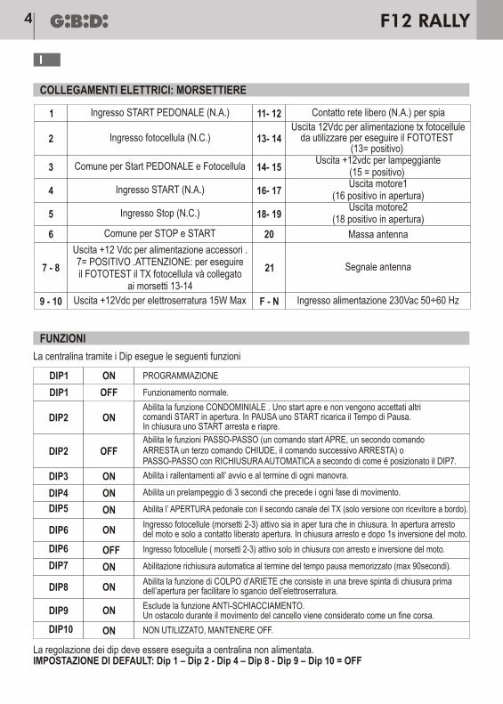
da utilizzare per eseguire il FOTOTEST(13= positivo)
3 Comune per Start PEDONALE e Fotocellula 14- 15 Uscita +12vdc per lampeggiante
(15 = positivo)
4 Ingresso START (N.A.) 16- 17 Uscita motore1
(16 positivo in apertura)
6 Comune per STOP e START 20 Massa antenna
5 Ingresso Stop (N.C.) 18- 19 Uscita motore2
(18 positivo in apertura)
7 - 8
Uscita +12 Vdc per alimentazione accessori .7= POSITIVO .ATTENZIONE: per eseguireil FOTOTEST il TX fotocellula và collegato
ai morsetti 13-14
21 Segnale antenna
Ingresso alimentazione 230Vac 50÷60 HzF - N9 - 10 Uscita +12Vdc per elettroserratura 15W Max
PROGRAMMAZIONE
Funzionamento normale.
Abilita i rallentamenti all’ avvio e al termine di ogni manovra.
Abilita un prelampeggio di 3 secondi che precede i ogni fase di movimento.
Abilita l’ APERTURA pedonale con il secondo canale del TX (solo versione con ricevitore a bordo).
Ingresso fotocellule ( morsetti 2-3) attivo solo in chiusura con arresto e inversione del moto.
NON UTILIZZATO, MANTENERE OFF.
Abilitazione richiusura automatica al termine del tempo pausa memorizzato (max 90secondi).
Abilita la funzione CONDOMINIALE . Uno start apre e non vengono accettati altricomandi START in apertura. In PAUSA uno START ricarica il Tempo di Pausa.In chiusura uno START arresta e riapre.
Ingresso fotocellule (morsetti 2-3) attivo sia in aper tura che in chiusura. In apertura arrestodel moto e solo a contatto liberato apertura. In chiusura arresto e dopo 1s inversione del moto.
Abilita la funzione di COLPO d’ARIETE che consiste in una breve spinta di chiusura primadell’apertura per facilitare lo sgancio dell’elettroserratura.
La regolazione dei dip deve essere eseguita a centralina non alimentata.IMPOSTAZIONE DI DEFAULT: Dip 1 – Dip 2 - Dip 4 – Dip 8 - Dip 9 – Dip 10 = OFF
Esclude la funzione ANTI-SCHIACCIAMENTO.Un ostacolo durante il movimento del cancello viene considerato come un fine corsa.
Abilita le funzioni PASSO-PASSO (un comando start APRE, un secondo comandoARRESTA un terzo comando CHIUDE, il comando successivo ARRESTA) oPASSO-PASSO con RICHIUSURA AUTOMATICA a secondo di come è posizionato il DIP7.
FUNZIONI
La centralina tramite i Dip esegue le seguenti funzioni
DIP1 ON
OFF
OFF
ON
ON
ON
ON
ON
ON
ON
OFF
ON
ON
DIP1
DIP2
DIP6
DIP8
DIP9
DIP2
DIP3
DIP4
DIP5
DIP6
DIP10
DIP7
F12 RALLY4
I
F12 RALLY 5
I
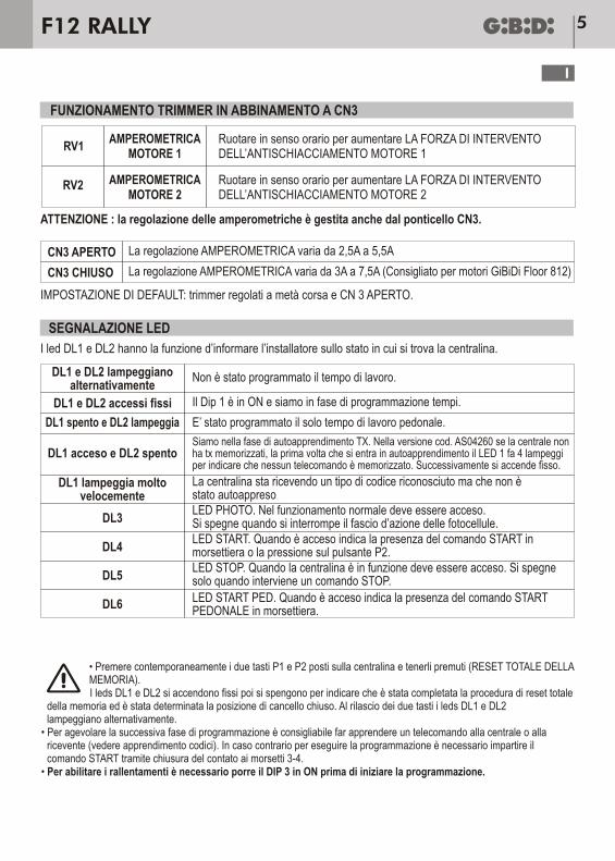
SEGNALAZIONE LED
FUNZIONAMENTO TRIMMER IN ABBINAMENTO A CN3
RV1
CN3 APERTO
CN3 CHIUSO
DL1 e DL2 lampeggianoalternativamente
DL1 e DL2 accessi fissi
DL3
DL4
DL5
DL6
DL1 spento e DL2 lampeggia
DL1 acceso e DL2 spento
DL1 lampeggia moltovelocemente
AMPEROMETRICAMOTORE 1
Ruotare in senso orario per aumentare LA FORZA DI INTERVENTODELL’ANTISCHIACCIAMENTO MOTORE 1
Ruotare in senso orario per aumentare LA FORZA DI INTERVENTODELL’ANTISCHIACCIAMENTO MOTORE 2
ATTENZIONE : la regolazione delle amperometriche è gestita anche dal ponticello CN3.
IMPOSTAZIONE DI DEFAULT: trimmer regolati a metà corsa e CN 3 APERTO.
I led DL1 e DL2 hanno la funzione d’informare l’installatore sullo stato in cui si trova la centralina.
La regolazione AMPEROMETRICA varia da 2,5A a 5,5A
La regolazione AMPEROMETRICA varia da 3A a 7,5A (Consigliato per motori GiBiDi Floor 812)
Non è stato programmato il tempo di lavoro.
Il Dip 1 è in ON e siamo in fase di programmazione tempi.
LED PHOTO. Nel funzionamento normale deve essere acceso.Si spegne quando si interrompe il fascio d’azione delle fotocellule.LED START. Quando è acceso indica la presenza del comando START inmorsettiera o la pressione sul pulsante P2.LED STOP. Quando la centralina è in funzione deve essere acceso. Si spegnesolo quando interviene un comando STOP.
LED START PED. Quando è acceso indica la presenza del comando STARTPEDONALE in morsettiera.
E’ stato programmato il solo tempo di lavoro pedonale.
La centralina sta ricevendo un tipo di codice riconosciuto ma che non èstato autoappreso
Siamo nella fase di autoapprendimento TX. Nella versione cod. AS04260 se la centrale nonha tx memorizzati, la prima volta che si entra in autoapprendimento il LED 1 fa 4 lampeggiper indicare che nessun telecomando è memorizzato. Successivamente si accende fisso.
AMPEROMETRICAMOTORE 2
RV2
• Premere contemporaneamente i due tasti P1 e P2 posti sulla centralina e tenerli premuti (RESET TOTALE DELLA MEMORIA).I leds DL1 e DL2 si accendono fissi poi si spengono per indicare che è stata completata la procedura di reset totale
della memoria ed è stata determinata la posizione di cancello chiuso. Al rilascio dei due tasti i leds DL1 e DL2 lampeggiano alternativamente.
• Per agevolare la successiva fase di programmazione è consigliabile far apprendere un telecomando alla centrale o alla ricevente (vedere apprendimento codici). In caso contrario per eseguire la programmazione è necessario impartire il comando START tramite chiusura del contato ai morsetti 3-4.
• Per abilitare i rallentamenti è necessario porre il DIP 3 in ON prima di iniziare la programmazione.
Al pr imo col legamento occorre far autoapprendere i tempi d i lavoro a l la centra l ina.Finché non viene eseguita la programmazione tempi il tasto Start funziona solo a uomo presente per far muovere, prima l’anta2 rallentata in chiusura fino al suo fine corsa quindi l’anta1 anch’essa fino al suo fine corsa. Durante tale operazione lo Stop e le fotocellule vengono ignorate.
ATTENZIONE:- è necessario usare i fermi meccanici di fine corsa;- la logica di programmazione dei tempi prevede che il motore 2 arrivi prima del motore 1 sul fermo
meccanico di chiusura.
IMPORTANTE: iniziare questa fase sempre dalla posizione di cancello completamente chiuso.
Posizionare il DIP 1 in ON per iniziare la programmazione :i leds DL1 e DL2 si accendono e la centralina emetterà dei BIP ad indicare ilnumero di cicli impostati per la manutenzione (Vedere paragrafo dedicato)
• Premere start: parte in apertura l’anta 1 e dopo 2 secondi anche l’anta 2• Quando l’anta 1 arriva contro il fermo meccanico di apertura si arresta (In assenza di fermo meccanico
premere start per arrestare l’anta 1 nella posizione desiderata)L’ANTA 1 SI FERMA
• Quando l’anta 2 arriva contro il fermo meccanico di apertura si arresta (In assenza di fermo meccanico premere nuovamente Star t per arrestare l’anta 2 nella posizione desiderata)
L’ANTA 2 SI FERMA
• La centralina inizia a contare il tempo pausa (max 90 secondi)• Trascorso il tempo pausa desiderato premere STARTL’ANTA 2 PARTE IN CHIUSURA
• La centrale comincia a contare il tempo di sfasamento (max 20 secondi)• Trascorso il tempo di sfasamento desiderato premere STARTL’ANTA 1 PARTE IN CHIUSURA
• La centrale non accetta altri comandi fino all ‘arresto delle 2 ante che avviene a seguito del raggiungimento dei rispettivi fermi meccanici di chiusura.
• Riportare il DIP1 in OFF
Se l’operazione di programmazione non è andata a buon fine per l’intervento della protezione antischiacciamento ruotare i trimmer RV1 ed RV2 in senso orario e, riposizionando il dip 1 in ON, ripetere le operazioni di programmazione (non è necessario resettare la memoria).Nel caso in cui il cancello fosse rimasto aperto senza aver memorizzato il tempo di lavoro, è possibile riportare il
(tempo lavoro, tempo pausa e tempo sfasamento ante)PROGRAMMAZIONE TEMPI
.
F12 RALLY6
I
E’ possibile far operare la centrale anche con un solo motore utilizzando l’uscita MOTORE 1 (morsetti 16 e 17).Procedere nel seguente modo:• Regolare il trimmer RV2 al massimo (ruotato in senso orario)• Cortocircuitare i morsetti 18 e 19 (motore 2)• Eseguire la programmazione tempi (Attenzione dopo la pausa desiderata occorre dare due comandi Start)• Al termine della fase di programmazione rimuovere il ponticello fatto tra i pin 18 e 19 ( !)
Dopo aver eseguito la programmazione dei tempi di lavoro, pausa e sfasamenti, è possibile programmare i tempi relativi al CICLO PEDONALE.In caso di centralina con radio a bordo (cod. AS04260) occorre prima autoapprendere il secondo tasto del radiocomando, quindi posizionare il Dip 5 in ON per abilitare la relativa funzione.INIZIARE LA PROGRAMMAZIONE PARTENDO DALLA CONDIZIONE DI CANCELLO COMPLETAMENTE CHIUSO.
IMPORTANTE: iniziare questa fase sempre dalla posizione di cancello completamente chiuso.
Posizionare il DIP 1 in ON per iniziare la programmazione: i leds DL1 e DL2 si accendono e la centralina emetterà dei BIP ad indicare il numero di cicli impostati per la manutenzione (Vedere paragrafo dedicato).
• Premere start pedonale (secondo canale del TX o contatto ai morsetti 1-3)L’ANTA 1 PARTE IN APERTURA
• Quando l’anta 1 arriva nella posizione desiderata premere nuovamente START PEDONALE (o attendere l’arresto dell’anta contro il relativo finecorsa meccanico di apertura)
L’ANTA 1 SI FERMA
• La centralina inizia a contare il tempo di pausa (Max 90 secondi)• Trascorso il tempo pausa desiderato premere START PEDONALEL’ANTA 1 PARTE IN CHIUSURA
• Attendere l’arresto del moto per raggiungimento del fermo meccanico di chiusura e riportare il DIP1 in OFF
Questa funzione consente di ridurre il tempo di pausa a 3sec. dall’intervento e successiva liberazione delle fotocellule.Come abilitare questa funzione: durante la programmazione tempi, quando il cancello è in pausa di apertura, intercettare le fotocellule per almeno cinque secondi.A questo punto un BIP segnala che è stata abilitata la funzione (di fatto diventa operativa solo al termine della fase di Programmazione).Proseguire con la fase di programmazione partendo dalla attesa del tempo di pausa.Per escludere questa funzione: ripetere la procedura di programmazione.
In questa situazione il reale tempo di pausa viene calcolato dal momento in cui si liberanole fotocellule.
RICHIUSURA RAPIDA
FUNZIONAMENTO CON UN SOLO MOTORE
PROGRAMMAZIONE CICLO PEDONALE
F12 RALLY 7
I
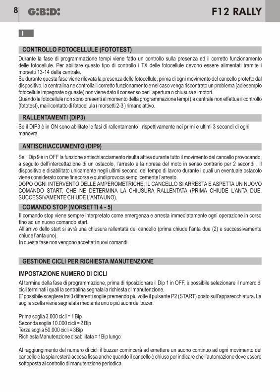
Il comando stop viene sempre interpretato come emergenza e arresta immediatamente ogni operazione in corso fino ad un nuovo comando start.All’arrivo dello start si avrà una chiusura rallentata del cancello (prima chiude l’anta due (2) e successivamente chiude l’anta uno).In questa fase non vengono accettati nuovi comandi.
GESTIONE CICLI PER RICHIESTA MANUTENZIONE
Al termine della fase di programmazione, prima di riposizionare il Dip 1 in OFF, è possibile selezionare il numero di cicli terminati i quali la centralina segnala la richiesta di manutenzione.E’ possibile scegliere tra 3 differenti soglie premendo più volte il pulsante P2 (START) posto sull’apparecchiatura. La soglia scelta viene segnalata mediante uno o più suoni del buzer.
Al raggiungimento del numero di cicli il buzzer comincerà ad emettere un suono continuo ad ogni movimento del cancello e la spia resterà accesa fissa anche quando il cancello è chiuso per indicare che l’automazione deve essere sottoposta al controllo di manutenzione periodica.
IMPOSTAZIONE NUMERO DI CICLI
Durante la fase di programmazione tempi viene fatto un controllo sulla presenza ed il corretto funzionamento delle fotocellule. Per abilitare questo tipo di controllo i TX delle fotocellule devono essere alimentati tramite i morsetti 13-14 della centrale.Se durante questa fase viene rilevata la presenza delle fotocellule, prima di ogni movimento del cancello protetto dal dispositivo, la centralina ne controlla il corretto funzionamento e nel caso venga riscontrato un problema (ad esempio fotocellule impegnate o guaste) non viene dato il consenso per l’ apertura o chiusura ai motori.Quando le fotocellule non sono presenti al momento della programmazione tempi (la centrale non effettua il controllo (fototest), ma il contatto di fotocellula ( morsetti 2-3 ) rimane attivo.
Se il Dip 9 è in OFF la funzione antischiacciamento risulta attiva durante tutto il movimento del cancello provocando, a seguito dell’intercettazione di un ostacolo, l’arresto e la ripresa del moto in senso contrario per 2 secondi . Il dispositivo e disabilitato unicamente negli ultimi secondi del tempo di lavoro durante i quali un eventuale ostacolo viene considerato come finecorsa e quindi provoca semplicemente l’arresto.DOPO OGNI INTERVENTO DELLE AMPEROMETRICHE, IL CANCELLO SI ARRESTA E ASPETTA UN NUOVO COMANDO START, CHE NE DETERMINA LA CHIUSURA RALLENTATA (PRIMA CHIUDE L’ANTA DUE, SUCCESSIVAMENTE CHIUDE L’ANTA UNO).
Se il DIP3 è in ON sono abilitate le fasi di rallentamento , rispettivamente nei primi e ultimi 3 secondi di ogni manovra.
CONTROLLO FOTOCELLULE (FOTOTEST)
RALLENTAMENTI (DIP3)
ANTISCHIACCIAMENTO (DIP9)
COMANDO STOP (MORSETTI 4 - 5)
F12 RALLY8
I
Per resettare il contatore del numero di cicli procedere nel seguente modo:• Togliere alimentazione alla centralina. Se presente, staccare anche la batteria• Fare un ponticello su CN4 pin 3 e 4• Ripristinare l’alimentazione: il buzer emetterà suoni intermittenti• Rimuovere il ponticello posto su CN4 A questo punto sono ripristinate le condizioni iniziali e la centralina
richiederà nuovamente l’intervento di manutenzione al raggiungimento delle le manovre impostate.• Se si vuole escludere definitivamente il suono del BUZZER, è possibile tagliando il ponticello JP1.
Premere il tasto P1 (LEARN). Il LED DL1 si accende per indicare che il ricevitore è pronto ad apprendere un telecomando, indifferentemente a DIP o Rolling-Code (riconoscimento automatico del tipo di codice). Dopo aver appreso un tipo di codice il sistema accetterà soltanto quella famiglia di codici, cioè se il primo è Rolling tutti gli altri dovranno essere Rolling.Ora si può premere il primo tasto di un Trasmettitore (oppure il 2°-3° o 4°). A codice appreso il ricevitore dà un comando alla centralina.Senza premere nuovamente il tasto P1 si possono apprendere altri telecomandi della stessa famiglia e così via fino all’apprendimento di tutti i telecomandi.Dopo aver appreso l’ultimo telecomando, attendere lo spegnimento del led DL1 (circa 6 secondi) ad indicare che il sistema è uscito dall’apprendimento tx ed è pronto per funzionare in modo normale. In caso di errore resettare la memoria dei codici, premendo il tasto P1 (il led DL1 si accende) e mantenendolo premuto fino a quando il LED DL1 non si spegne.Al rilascio del tasto il led Dl1 dà un lampeggio (per indicare che la memoria è vuota) poi si riaccende e il sistema è pronto ad apprendere di nuovo un telecomando (indifferentemente codice DIP o Rolling-Code).
La centralina nella versione cod. AS04260 è già comprensiva di Modulo radio 433 Mhz e DECODIFICA (Codici DIP28bit, a DIP 12bit, Rolling-code).Max 200 diversi codici memorizzabili.
Dopo aver fatto apprendere al sistema un telecomando in modo manuale (premendo il tasto S1) è possibile abilitare l’auto apprendimento di altri telecomandi della stessa famiglia senza accedere alla centrale.In prossimità della centrale premere insieme tasto 1 e 2 del trasmettitore già appreso per 2 secondi, quindi premere il tasto di un nuovo telecomando per autoapprenderlo.
E’ possibile applicare una batteria tampone per il funzionamento in assenza di tensione di rete 230Vac.Durante il funzionamento esclusivamente con batteria tampone l’operatore risulta essere più lento.Tale batteria deve essere collegata ai terminali CN11, il polo positivo, e al CN10 quello negativo.Batteria consigliata 12Vdc 1,9-2 Ah.
ATTENZIONE: durante il funzionamento con batteria tampone viene esclusa automaticamente la funzione antischiacciamento e il lampeggiatore segnala questa situazione mediante un lampeggio più lento.
AZZERAMENTO CICLI
MODULO RADIO
APPRENDIMENTO CODICI
APPRENDIMENTO TELECOMANDI ROLLING-CODE SENZA ACCEDERE ALLA CENTRALINA
BATTERIA TAMPONE
F12 RALLY 9
I
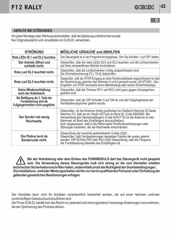
ANOMALIE POSSIBILI CAUSE E SOLUZIONI
Led rossi DL1 e DL2 accesi Centrale in fase di programmazione. Portare Dip 1 OFF
Controllare che l’antenna sia posizionata correttamente (calza morsetto 20anima morsetto 21 se apparecchiatura con radio a bordo, cod. AS04260.Se utilizzato ricevitore a innesto (cod. AU01710) l’antenna và collegata aimorsetti presenti sul ricevitore.Controllare che nelle vicinanze non ci siano fonti di disturbo ponti radio odisturbi che ne limitano la portata.
Controllare che i trimmer RV1 ed RV2 non siano completamente ruotatiin senso antiorarioControllare che il DIP5 sia in ON e che il tasto pedonale del telecomandosia stato precedentemente appreso.
Controllare che siano correttamente collegate le fotocellule.Controllare il fusibile F2 (10 A)
Controllare che l’ingresso STOP sia collegato a un pulsante normalmentechiuso o sia stato fatto il ponticello tra i morsetti 5 e 6 (ATTENZIONE:l’intervento dello STOP provoca un arresto funzionale e NON di sicurezza)
Verifica dei codici massimi memorizzabili (200). Verifica se stiamoapprendendo telecomandi della stessa famiglia del primo: DIP-SWITCHo ROLLING.Verificare che la frequenza del radiocomando sia la stessa del ricevitore.
Verificare che i leds rossi DL5 e DL3 siano accesi e verificare il buonfunzionamentodelle fotocellule.
L’operatore non apre non chiude
Led rosso DL5 spento
Il trasmettitore hapoca portata
La scheda non apprendeil codice TX
Dopo tempo lavoro non richiude
Premendo il 2° tasto del telecomandonon si effettua il pedonale
Led rosso DL3 spento
Mentre si esegue il cablaggio e/o l’inserimento del MODULO RADIO l’apparecchiatura non deve essere alimentata.
L’impiego di questa apparecchiatura deve attenersi rigorosamente alle indicazioni fornite dal costruttore pena l’annullamento degli estremi di garanzia.L’installazione e/o la manutenzione deve essere eseguita solo da personale qualificato e nel rispetto delle disposizioni legislative Vigenti.
Il costruttore non può considerarsi responsabile per eventuali danni causati da uso improprio e/o irragionevole.LA Gi.Bi.Di. si riserva il diritto, in qualsiasi momento e senza preavviso alcuno, di apportare modifiche ispirate al miglioramento del prodotto.
Prima di ogni montaggio o intervento di manutenzione,assicurarsi di aver staccato l’alimentazione.Utilizzare solamente accessori e ricambi originali Gi.Bi.Di.
RISOLUZIONE ANOMALIE
F12 RALLY10
I
CANCELLO COMPLETAMENTECHIUSO
DIP 1 ONBIP PER CICLI DIMANUTENZIONE
PARTE ANTA 1 PARTE ANTA 2
PARTE ANTA 1
PARTE ANTA 2
STOP ANTA 1
STOP ANTA 2
BIP DI CONFERMA
OPERAZIONE FACOLTATIVA
START
START O FINE CORSA MECCANICO
START O FINE CORSA MECCANICO
PER ABILITARE LA RICHIUSURARAPIDA INTERCETTARE LE FOTO
ATTENDERE TEMPODI PAUSA MAX 90s
START
START
ATTENDERE TEMPODI SFASAMENTO MAX 90s
ATTENDERE CHIUSURAFINO AI FERMI MECCANICI
CON IL TASTO START E’POSSIBILE CAMBIARE IL
NUMERO DI CICLIPER LA MANUTENZIONE
POSIZIONARE DIP 1 IN OFF
2S
5S
FASI PER LA PROGRAMMAZIONE TEMPI
F12 RALLY 11
I
Ammistratore DelegatoOliviero Arosio
Dichiarazione di conformità CEIl fabbricante:
GI.BI.DI.
Via Abetone Brennero, 177/B,46025 Poggio Rusco (MN) ITALY
Dichiara che i prodotti:
APPARECCHIATURA ELETTRONICA F12 RALLY
Sono conformi alle seguenti Direttive CEE:
•
e che sono state applicate le seguenti norme armonizzate:
•
•
Data 16/07/08
S.r.l.
Direttiva LVD 2006/95/CE e successive modifiche;
• Direttiva EMC 2004/108/CE e successive modifiche;
EN60335-1
EN61000-6-2, EN61000-6-3
F12 RALLY12
I
TECHNICAL CHARACTERISTIC
TECHNICAL SPECIFICATIONS / FUNCTIONS
It is complete in operating range (condominium, step-by-step, step-by-step with reclosing, pedestrian, pedestrian with reclosing, water hammer, anti-crushing and deceleration) and adjustments (run time, pedestrian run time, pause time, phase shift time and amperometric threshold).It is versatile in its options (deceleration during opening and closing, electronic anti-crushing, photocell operation control, gate open warning light, built-in or plug-in radio).It is easy to install thanks to the extractable terminals and the silk-screen printing on the printed circuit indicating the connections and functions.
F12 RALLY/AS04220
Electronic control unit for automation of one ortwo 12V motors for swing gates
1 o 2
12 Vdc 8W max
12Vdc 2W max
12Vdc 15W max
-20°C +60°C
Control unit
Type
Power supply
No. of motors
Accessory power supplyPhotocell TX power supply for TEST
Flashlight
Radio receiverOperating temperature
Run time 90s max
Motor power supply 12 Vdc
13
UK
F12 RALLY
INSTALLATION
Use glands adequate to ensure proper mechanical connection of cable and maintain the box protection degree IP55. (2)
2
radio receiver
230 VAC, single-phase, 50/60 Hz
WARNINGS FOR THE USER
INSTALLATION WARNINGS
In the event of an operating fault or failure, cut the power upstream of the control unit and call Technical Service.Periodically check functioning of the safety devices. Any repairs must be carried out by specialised personnel using original and certified materials. The appliance is not to be used by children or people with reduced physical, sensory or mental capabilities, or lack of experience and knowledge, unless they have been given supervision or instruction.Do not touch the card for adjustments and/or maintenance.
• Before proceeding with installation, fit a magnetothermal or differential switch with a maximum capacity of 10A upstream of the system. The switch must guarantee omnipolar separation of the contacts with an opening distance of at least 3 mm.
• To prevent possible interference, differentiate and always keep the power cables (minimum cross-section1.5 mm²) separate from the signal cables (minimum cross-section 0.5 mm²).
• Make the connections referring to the following tables and to the attached screen-print. Be extremely careful to connect in series all the devices that are connected to the same N.C. (normally closed) input, and in parallel all the devices that share the same N.O. (normally open) input. Incorrect installation or improper use of the product may compromise system safety.
• Keep all the materials contained in the packaging away from children, since they pose a potential risk.• The manufacturer declines all responsibility for improper functioning of the automated device if the original
components and accessories suitable for the specific application are not used. • After installation, always carefully check proper functioning of the system and the devices used.• This instruction manual addresses persons qualified for installation of "live equipment". Therefore, good
technical knowledge and professional practice in compliance with the regulations in force are required.• Maintenance must be carried out by qualified personnel.• Before carrying out any cleaning or maintenance operation, disconnect the control unit from the mains.• This control unit may only be used for the purpose for which it was designed.• Check the aim of the final use and make sure that all safety measures are taken.• Use of the product for purposes different from the intended use has not been tested by the manufacturer,
therefore any work is carried out on full responsibility of the installer.• Mark the automated device with visible warning plates. • Warn the user that children or animals may not play or stand around near the door.• Appropriately protect the danger points (for example, using a sensitive frame).
WARNING: IMPORTANT SAFETY INSTRUCTIONS.It is very important to follow the present instructions for your own safety.Please keep this manual.
2 Photocell input (NC) 13- 1412VDC output for photocell TX power
supply to use torun the PHOTOTEST (13 = positive)
3 Common for PEDESTRIAN STARTand Photocell 14- 15
+12VDC output for flashlight(15 = positive)
4 START input (NO) 16- 17 Motor 1 output
(16 = positive during opening)
6 Common for STOP and START 20 Antenna ground
5 STOP input (NC) 18- 19 Motor 2 output
(18 = positive during opening)
7 - 8
+12 VDC output for accessory power supply.7 = POSITIVE. CAUTION: to run the
PHOTOTEST the photocell TX must beconnected to terminals 13-14.
21 Antenna signal
Power supply input 230 VAC 50-60 HzF - N9 - 10 +12VDC output for electric lock 15W
PROGRAMMING
Normal operation
Enables deceleration at the beginning and end of each manoeuvre
Enables pre-flashing of 3 seconds prior to each movement phase
Enables pedestrian opening with the second channel of the TX (only version with built-in receiver)
Photocell input (terminals 2-3) active only during closing with stop and inversion of motion.
NOT USED, HOLD IN OFF.
Enables automatic reclosing at the end of the pause time stored (max. 90 seconds).
Enables the CONDOMINIUM function. One start command opens and no further startcommands are accepted during opening. During PAUSE one start command reloads thePause Time. During CLOSING one start command stops and reopens.
Photocell input (terminals 2-3) active during both opening and closing. During opening, stops the motion andopens only when the contact has been freed. During closing, stops and after 1 second inver ts the motion.
Enables the WATER HAMMER function which consists of a short closing thrust beforeopening to facilitate release of the electric lock
The dip switches must be adjusted when the control unit is not powered.DEFAULT SETTINGS: Dip 1 – Dip 2 - Dip 4 – Dip 8 - Dip 9 – Dip 10 = OFF
Disables the ANTI-CRUSHING function.An obstacle found during gate movement is considered as a limit switch.
Enables the STEP-BY-STEP function (one start command opens, a second command stopsand a third command closes, the next command stops) or STEP-BY-STEP with AUTOMATICRECLOSING depending on how DIP7 is set.
FUNCTIONS
The control unit performs the following functions by means of the dip switches:
DIP1 ON
OFF
OFF
ON
ON
ON
ON
ON
ON
ON
OFF
ON
ON
DIP1
DIP2
DIP6
DIP8
DIP9
DIP2
DIP3
DIP4
DIP5
DIP6
DIP10
DIP7
ELECTRICAL CONNECTIONS: TERMINAL BOARDS
15
UK
F12 RALLY
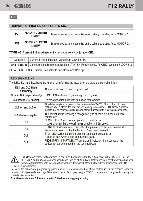
LED SIGNALLING
TRIMMER OPERATION COUPLED TO CN3
RV1
CN3 OPEN
CN3 CLOSED
DL1 and DL2 flashalternately
DL1 and DL2 on permanently
DL3
DL4
DL5
DL6
DL1 off and DL2 flashing
DL1 on and DL2 off
DL1 flashes very fast
MOTOR 1 CURRENTLIMITER
Turn clockwise to increase the anti-crushing operating force MOTOR 1.
Turn clockwise to increase the anti-crushing operating force MOTOR 2.
WARNING: Current limiter adjustment is also controlled by jumper CN3.
DEFAULT SETTINGS: trimmers adjusted to half-stroke and CN3 open.
The LEDs DL1 and DL2 have the function of informing the installer of the state the control unit is in.
Current limiter adjustment varies from 2.5A to 5.5A
Current limiter adjustment varies from 3A to 7,5A (Recommended for GiBiDi operators FLOOR 812)
The run time has not been programmed.
DIP1 is ON and time programming is in progress
PHOTO LED. During normal operation it must be on.It goes off when the photocell range of action is interrupted.START LED. When it is on it indicates the presence of the start command onthe terminal board, or that the button P2 has been pressed.STOP LED. When the control unit is in operation it must be on.It goes off only when a stop command is given.PEDESTRIAN START LED. When it is on it indicates the presence of the pedestrian start command on the terminal board.
Only the pedestrian run time has been programmed.
The control unit is receiving a recognised type of code but it has not beenself-learned.
TX self-learning is in progress. In the version code AS04260, if the control unit doesnot have any TX stored, the first time self-learning is accessed, LED1 flashes 4 times toindicate that no remote control has been stored. Subsequently it stays on permanently.
MOTOR 2 CURRENTLIMITER
RV2
• Simultaneously press the two buttons P1 and P2 on the control unit and hold them down (MEMORY RESET). The LEDs DL1 and DL2 come on permanently and then go off to indicate that the memory reset procedure has been completed and that the gate-closed position has been determined. When the two buttons are released the LEDs
DL1 e DL2 flash alternately.• To make the subsequent programming phase easier, it is recommended to let the control unit or the receiver learn one
remote control (see code learning). Otherwise, to execute programming a START command must be given by closing the contact on terminals 3-4.
• To enable deceleration, DIP3 must be set to ON before starting programming.
16
UK
F12 RALLY
(run time, pause time and wing phase shift time)
The first time the control unit is connected, it must self-learn the run times.As long as the times have not been programmed, the Start key functions only with dead man’s logic to move first wing 2 in slow motion during closing up to its limit switch and then wing 1 up to its limit switch. During this operation the Stop and the photocells are ignored.
WARNING:- the mechanical end-stops must be used;- the timeprogramming logic requires that motor 2 arrives before motor 1 at the mechanical closing stop.
IMPORTANT: Always start this phase with the gate completely closed.
Position DIP1 to ON to start programming: the LEDs DL1 and DL2 come on and the control unit will emit some BEEPS to indicate the number of cycles set for maintenance (see dedicated paragraph).
• Press Start: wing 1 starts opening and after 2 seconds wing 2• When wing 1 arrives against the mechanical opening stop it halts (in the absence of the mechanical stop, press Start to stop wing 1 in the desired position).WING 1 STOPS
• When wing 2 arrives against the mechanical opening stop it halts (in the absence of the mechanical stop, again press Start to stop wing 2 in the desired position).WING 2 STOPS
• The control unit starts counting the pause time (max. 90 seconds)• When the desired pause time has elapsed, press STARTWING 2 STARTS CLOSING
• The control unit starts counting the phase shift time (max. 20 seconds)• When the desired phase shift time has elapsed, press STARTWING 1 STARTS CLOSING
• The control unit does not accept any further commands until both wings have stopped, which occurs when they have reached their respective mechanical closing stops.
• Set DIP1 to OFF.
If the programming operation was not successful because of the anti-crushing device cutting in, turn the trimmers RV1 and RV2 clockwise,reset DIP1 to ON, and repeat the programming operation (the memory does not have to be reset). Should the gate remain open without therun time having been stored, it can be moved to the closing position by pressing and holding down the START button.
TIME PROGRAMMING
.
17
UK
F12 RALLY
After programming the run, pause and phase shift times, the PEDESTRIAN CYCLE times can be programmed.In the case of the control unit with built-in radio (code AS04260), first self-learn the second key of the radio control and then set DIP5 to ON to enable the relevant function.START PROGRAMMING WITH THE GATE COMPLETELY CLOSED.
IMPORTANT: Always start this phase with the gate completely closed.
Set DIP1 to ON to start programming: the LEDs DL1 and DL2 come on and the control unit will emit some BEEPS to indicate the number of cycles set for maintenance (see dedicated paragraph).
• Press Pedestrian Start (second TX channel or contact on terminals 1-3)WING 1 STARTS OPENING
• When wing 1 arrives in the desired position again press Pedestrian Start (or wait for the wing to stop against the relevant mechanical opening stop).
WING 1 STOPS
• The control unit starts counting the pause time (max. 90 seconds)• When the desired pause time has elapsed, press Pedestrian StartWING 1 STARTS CLOSING
• Wait for the motion to stop when the mechanical closing stop has been reached and set DIP1 to OFF.
This function allows reducing the pause time to 3 sec. from activation and subsequent freeing of the photocells.How to enable this function: during time programming, when the gate is in opening pause, intercept the photocells for at least five seconds.At this point, a BEEP will signal that the function has been enabled (in fact, it becomes operational only at the end of the programming phase).Continue with the programming phase starting from the pause time delay.To disable this function: repeat the programming procedure.
In this condition the real pause time is calculated from the moment in which the photocellsare freed.
The control unit can be made to operate with only one motor using the MOTOR 1 output (terminals 16 and 17).Proceed as follows:• Adjust trimmer RV2 to the maximum (turned clockwise)• Short-circuit terminals 18 and 19 (motor 2)• Execute time programming (N.B. after the desired pause two Start commands must be given)• At the end of the programming phase, remove the jumper between pin 18 and 19 (!).
PADESTRIAN CYCLE PROGRAMMING
OPERATION WITH ONLY ONE MOTOR
FAST RECLOSING
18
UK
F12 RALLY
During the time programming phase, a test is run to check for the presence and proper functioning of the photocells.To enable this type of test the photocell transmitters must be powered through terminals 13-14 of the control unit.If the presence of photocells is detected during this phase, before each gate movement protected by the device, the control unit tests proper functioning and if a problem is found (for example, photocells engaged or broken) the motors are not given the OK for opening or closing.When the photocells are not present when the times are programmed, the control unit does not run the phototest, but the photocell contact (terminals 2-3) remains active.
If DIP3 is ON, the deceleration phases are enabled, respectively in the first and last 3 seconds of each manoeuvre
If DIP9 is OFF, the anti-crushing function is active during the entire gate movement causing, when an obstacle is found, stopping and restarting of the motion in the opposite direction for 2 seconds. The device is disabled only in the last seconds of the run time during which any obstacle is considered as a limit switch and hence simply causes stopping.EACH TIME AFTER THE CURRENT LIMITERS HAVE CUT IN, THE GATE STOPS AND WAITS FOR A NEW START COMMAND, WHICH DETERMINES DECELERATED CLOSING (WING2 CLOSES FIRST AND THEN WING 1).
The Stop command is always interpreted as an emergency and immediately stops any operation in progress until a new Start command is given.When the Start command arrives, the gate will close in slow motion (wing 2 closes first and then wing 1).No new commands are accepted during this phase.
CYCLE CONTROL FOR MAINTENANCE REQUEST
PHOTOCELL TEST (PHOTOTEST)
DECELARATION (DIP3)
ANTI-CRASHING (DIP9)
STOP COMMAND (TERMINALS 4 - 5)
SETTING THE NUMBER OF CYCLES
At the end of the programming phase, before setting DIP1 to OFF, it is possible to select the number of cycles after which the control unit will signal that maintenance is required.Three different thresholds can be selected by pressing the button P2 (START) on the control unit.The selected threshold is signalled by means of one or more beeps.
When the number of cycles has been reached, the buzzer will start emitting a continuous sound each time the gate is moved and the light will remain on permanently when the gate is closed to indicate that the automated device must undergo the required periodic maintenance.The buzzer can be disabled by cutting the jumper J1. In this case all the warnings signalled by the buzzer will be disabled.
19
UK
F12 RALLY
The buffer battery can be used when the 230 Vac mains power fails to ensure continued functioning of the operator.During operation with only the buffer battery, the operator is slightly slower.The positive pole of the battery must be connected to the CN11 terminal and the negative one the CN10 terminal.Recommended battery: 12VDC, 1.9-2 Ah.
WARNING: during operation with a buffer battery the anti-crushing function is automatically disabled and the flash light signals this condition by flashing slower.
To reset the cycle counter, proceed as follows:• Cut the power to the control unit. If present, also disconnect the battery.• Place a jumper on CN4 between pin 3 and 4• Restore power: the buzzer will emit intermittent sounds• Remove the jumper from CN4. At this point, the initial conditions have been reset and the control unit will again
request maintenance when• the set number of cycles has been reached.• If you want to definitively cut out the sound of the BUZZER, cut the jumper JP1.
After letting the system learn a remote control manually (pressing the key S1), self-learning of other remote controls of the same family can be enabled without accessing the control unit.Near the control unit simultaneously press key 1 and 2 of the transmitter already learned for 2 seconds. Then press the key of a new remote control to self-learn it.
Press the button P1 (LEARN). The LED DL1 comes on to indicate that the receiver is ready to learn a remote control, whether Dip Switch or Rolling-code (automatic recognition of the code type). After learning a type of code the system will accept only that family of codes, i.e. if the first is Rolling all the others must be Rolling.Now press the first key of a transmitter (or the 2nd, 3rd or 4th). When the code has been learned the receiver gives a command to the control unit. Without pressing P1 again, further remote controls of the same family can be learned one after the other until all the remote controls have been learned.After learning the last remote control, wait for the LED DL1 to go off (about 6 seconds) which indicates that the system has exited transmitter learning and is ready to operate normally.If an error is made, reset the code memory by pressing P1 (the LED DL1 comes on) and holding it down until the LED DL1 goes off.When the key is released, the LED DL1 flashes once (to indicate that the memory is empty) and then comes back on, and the system is ready to once again learn a remote control whether Dip Switch or Rolling-Code.
The control unit in the version code AS04260 includes a 433 MHz radio module and DECODING (28-bit dip switch code, 12-bit dip switch code, rolling-code). A maximum of 200 different codes can be stored.
CYCLE RESET
RADIO MODULE
ROLLING-CODE REMOTE CONTROL LEARNING WITHOUT ACCESSING THE CONTROL UNIT
CODE LEARNING
BUFFER BATTERY
20
UK
F12 RALLY
FAULT POSSIBLE CAUSES AND SOLUTIONS
Red LEDs DL1 and DL2 on Control unit in programming phase. Set DIP1 to OFF
Check that the antenna is positioned properly (braid - terminal 20, core -terminal 21, if a control unit with built-in radio, code AS04260).If using a plug-in receiver (code AU01710), the antenna must be connected to the terminals on the receiver.Check that there are no sources of disturbance or radio links in thevicinity which limit the range.
Check that the trimmers RV1 and RV2 are not completely turned anticlockwise
Check that DIP5 is set to ON and that the pedestrian key of the remotecontrol has been learned.
Check that the photocells are properly connected.Check the fuse F2 (10 A).
Check that the STOP input is connected to a normally closed button orthat a jumper has been placed between terminals 5 and 6(CAUTION: STOP causes a functional stop NOT a safety stop)
Check that the max. number of codes (200) storable has not been reached.Check if remote controls of the same family as the first are being learned:DIP- SWITCH or ROLLING.Check that the frequency of the radio control is the same as that of the receiver.
Check that the red LEDs DL5 and DL3 are on and check goodfunctioning of the photocells.
The operator does not openor close
Red LED DL5 off
The transmitter hasa short range
The card does not learnthe TX code
After run time does not reclose
When pressing the 2nd key ofthe remote control, the pedestrian
function is not activated
Red LED DL3 off
When wiring or inserting the RADIO MODULE, the control unit must not be powered.The control unit must be used strictly following the instructions provided by the manufacturer on
pain of forfeiture of the guarantee.Installation and/or maintenance must be carried out by qualified personnel in compliance with the provisions of the laws in force.
The manufacturer cannot be held responsible for damage caused by improper and/or irrational use.Gi.Bi.Di. reserves the right to make modifications at any time and without prior notice in order to improve the product.
Before any installation or maintenance operation, ensure that the power has been cut !!Only use original Gi.Bi.Di. spare parts and accessories.
TROUBLESHOTTING
21
UK
F12 RALLY
GATE COMPLETELYCLOSED
DIP 1 ONBEEP FOR
MAINTENANCE CYCLES
START WING 1 START WING 2
START WING 1
START WING 2
STOP WING 1
STOP WING 2
CONFIRMATION BEEP
OPTIONAL OPERATION
START
START OR MECHANICAL STOP
START OR MECHANICAL STOP
TO ENABLE FAST RECLOSINGINTERCEPT PHOTOCELLS WAIT
WAIT FOR PAUSE TIMEMAX. 90 s
START
START
WAIT FOR PHASESHIFT TIME MAX. 20 s
WAIT FOR CLOSINGUP TO MECHANICAL STOPS
THE START KEY CAN BEUSED TO CHANGE THE
NUMBER OF CYCLES FORMAINTENANCE
SET DIP1 TO OFF
2S
5S
TIME PROGRAMMING PHASES
22
UK
F12 RALLY
CE Declaration of conformityThe manufacturer:
GI.BI.DI. S.r.l.
Via Abetone Brennero, 177/B,46025 Poggio Rusco (MN) ITALY
Declares that the products:
ELECTRONIC CONTROL UNIT F12 RALLY
are in conformity with the following CEE Directives:
•
• EMC Directive 2004/108/CE and subsequent amendments;
and that the following harmonised standards have been applied:
•
•
Date 16/07/08
LVD Directive 2006/95/CE and subsequent amendments;
EN60335-1
EN61000-6-2, EN61000-6-3
Managing DirectorOliviero Arosio
23
UK
F12 RALLY
CARACTÉRISTIQUES TECHNIQUES
CARACTERISTIQUES TECHNIQUES / FONCTIONS
Il est complet, grâce à sa gamme de fonctionnements (copropriété, pas à pas, pas à pas avec refermeture, fonction piéton, fonction piéton avec refermeture, coup de bélier, anti-écrasements et ralentissements) et aux réglages (temps de service, temps de service fonction piéton, temps de pause, temps de déphasage et seuil ampèremétrique).Il est polyvalent, grâce à ses options (ralentissements en ouverture et fermeture, anti-écrasement électronique, contrôle du fonctionnement des cellules photoélectriques, voyant lumineux de signalisation grille ouverte, radio à bord ou à enclenchement).Il est facile à installer grâce aux bornes extractibles et aux sérigraphies se trouvant sur le circuit imprimé, indiquant les connexions et les fonctions.
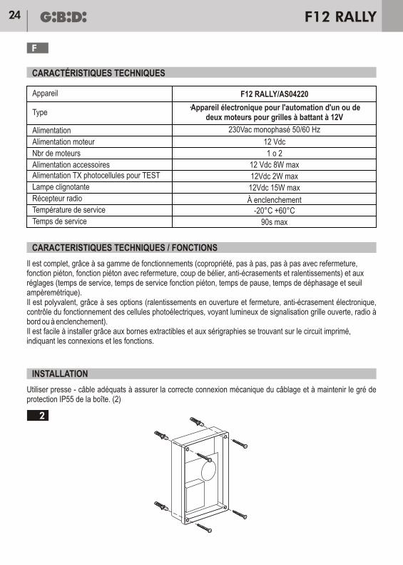
F12 RALLY/AS04220
·Appareil électronique pour l'automation d'un ou dedeux moteurs pour grilles à battant à 12V
1 o 2
12 Vdc 8W max
12Vdc 2W max
12Vdc 15W max
-20°C +60°C
Alimentation TX photocellules pour TEST
90s max
12 Vdc
INSTALLATION
Utiliser presse - câble adéquats à assurer la correcte connexion mécanique du câblage et à maintenir le gré de protection IP55 de la boîte. (2)
24
F
F12 RALLY
Appareil
Type
Alimentation
Nbr de moteurs
Alimentation moteur
Lampe clignotante
Alimentation accessoires
Récepteur radio
Température de service
Temps de service
2
À enclenchement
230Vac monophasé 50/60 Hz
AVERTISSEMENTS POUR L'UTILISATEUR
AVERTISSEMENTS POUR L'INSTALLATION
En cas de panne ou de dysfonctionnements, il faut couper l'alimentation en amont de l'appareil et appeler le service d'assistance technique.Il faut contrôler périodiquement le fonctionnement des dispositifs de sécurité.Les éventuelles réparations doivent être exécutées par un personnel spécialisé qui utilise des matériels d'origine et certifiés.Le produit ne doit pas être utilisé par enfants ou personnes avec réduites capacités physiques, sensoriales ou mentales, ou sans expérience et connaissance, à moins qu'elles n'aient pas été correctement instruitesNe pas accéder à la fiche pour régulations et/ou manutentions.
• Avant d'effectuer la mise en place, il faut prévoir en amont de l'installation un interrupteur magnétique et thermique ou différentiel ayant une capacité maximum de 10A. L'interrupteur doit assurer une séparation omnipolaire des contacts, avec une distance d'ouverture d'au moins 3 mm.
• Pour éviter de possibles interférences, il faut différencier et toujours maintenir séparés les câbles de puissance (section minimum 1,5mm²) des câbles de signal (section minimum 0,5mm²).
• Il faut effectuer les connexions en se référant aux tableaux suivants et à la sérigraphie jointe. Il faut faire particulièrement attention à raccorder en série tous les dispositifs qui doivent être connectés à la même entrée N.F. (normalement fermée) et en parallèle tous les dispositifs qui partagent la même entrée N.O. (normalement ouverte). Une mauvaise installation ou une mauvaise utilisation du produit peut compromettre la sécurité de l'installation.
• Tous les matériaux se trouvant dans l'emballage ne doivent pas être laissés à la portée des enfants, car ils peuvent être dangereux.
• Le constructeur décline toute responsabilité, quant au bon fonctionnement de l'automation, en cas d'utilisation de composants et d'accessoires n'étant pas de sa production et inappropriés à l'utilisation prévue.
• Après la mise en place, il faut toujours contrôler avec attention, le bon fonctionnement de l'installation et des dispositifs utilisés.
• Ce Manuel d'instructions s'adresse aux personnes autorisées à effectuer la mise en place "d'appareils sous tension". Il faut donc avoir une bonne connaissance de la technique, exercée comme profession et conformément aux réglementations en vigueur.
• La maintenance doit être effectuée par un personnel qualifié.• Avant d'effectuer toute opération de nettoyage ou de maintenance, il faut débrancher l'appareil des réseaux
d'alimentation électrique.• L'appareil ici décrit doit être utilisé uniquement pour l'emploi pour lequel il a été conçu :• Vérifier le bût de l'utilisation finale et s'assurer de prendre toutes les sûretés nécessaires• L'utilisation des produits et leur destination à des usages différents de ceux prévus, n'a pas été expérimentée par
le constructeur, les travaux exécutés sont donc sous l'entière responsabilité de l'installateur. • Il faut signaler l'automation à l'aide de plaques de mise en garde, qui doivent être parfaitement visibles.• Il faut avertir l'utilisateur qu'il est interdit que des enfants ou des animaux ne jouent ou ne stationnent à proximité
de la grille.• Il faut protéger comme il se doit les points à risque (par exemple à l'aide d'une membrure sensible).
ATTENTION: IMPORTANTES INSTRUCTIONS DE SECURITE.C'est important pour la sûreté des personnes suivre ces instructions - ci.Conserver le présent manuel d'instructions
25
F
F12 RALLY
1 Entrée START FONCTION PETION (N.O.) 11- 12 Contact relais libre ( N.O.) pour voyant
2 Ingresso fotocellula (N.C.) 13- 14Sortie 12vdc pour alimentation cellule
émettrice 13- 14 photoélectriques à utiliserpour exécuter le TEST (13= positif)
3 Commune pour Start FONCTION PIETON
et cellule photoélectrique 14- 15Sortie +12vcc pour clignotant
(15 = positif)
4 Entrée START ( N.O.) 16- 17 Sortie moteur 1
(16 positif en ouverture)
6 Commune pour STOP et START 20 Masse antenne
5 Entrée Stop (N.F.) 18- 19 Sortie moteur 2
(18 positif en ouverture)
7 - 8
Sortie +12 Vdc pour alimentation accessoires.7= POSITIF. ATTENTION: pour exécuter leTEST l’ÉMETTEUR cellule photoélectrique
Valide les ralentissements au démarrage et à la fin de chaque manoeuvre.
Valide un pré-clignotement de 3 secondes qui précède chaque phase de fonctionnement.
Valide l’OUVERTURE fonction piéton avec le deuxième canal ÉMETTEUR (uniquementversion avec récepteur à bord).
Entrée cellules photoélectriques (bornes 2-3) activée seulement en fermature avec arrêt etinversion du mouvement.
NON UTILISE, MAINTENIR OFF.
Validation refermeture automatique à la fin du temps de pause mémorisé (90 secondes maxi).
Valide la fonction COPROPRIETE. Une commande START ouvre et d’autres commandesSTART ne sont pas acceptées en ouverture. En PAUSE une commande START relance l Temps de Pause. En fermeture une commande START arrête et ouvre de nouveau.
Entrée cellules photoélectriques (bornes 2-3) activée en ouver ture comme en fermeture.En ouver ture arrêt du mouvement et ouver ture seulement après le dégagement du contact.En fermeture arrêt et après 1 seconde, inversion du mouvement.
Valide la fonction de COUP DE BELIER qui est une brève poussée en fermeture avantl’ouverture, pour faciliterle décrochage de l’électroserrure
Le réglage des DIP doit être exécuté lorsque l’unité est hor tension.PARAMETRAGE PAR DEFAUT : DIP1-DIP2-DIP 4 DIP8-DIP9-DIP10 = OFF.
Exclut la fonction ANTI-ECRASEMENT.Un obstacle pendant l’actionnement de la grille est considéré comme un fin de course.
Valide les fonctions PAS A PAS (une commande START OUVRE, une deuxième commandeARRETE, une troisième commande FERME, la commande suivante ARRETE) ou PAS APAS avec REFERMETURE AUTOMATIQUE en fonction de la position du DIP 7.
FONCTIONS
A l’aide des DIP l’unité exécute les fonctions suivantes
DIP1 ON
OFF
OFF
ON
ON
ON
ON
ON
ON
ON
OFF
ON
ON
DIP1
DIP2
DIP6
DIP8
DIP9
DIP2
DIP3
DIP4
DIP5
DIP6
DIP10
DIP7
BRANCHEMENTS ELECTRIQUES: BORNIERS
26
F
F12 RALLY
SIGNALISATION LED
FONCTIONNEMENT TRIMMER EN ACCOUPLEMENT AVEC CN3
RV1
CN3 OUVERTE
CN3 FERME
DL1 et DL2 clignotentalternativement
DL1 et DL2 allumées fixes
DL3
DL4
DL5
DL6
DL1 éteinte et DL2 clignote
DL1 allumée et DL2 éteinte
DL1 clignote trèsrapidement
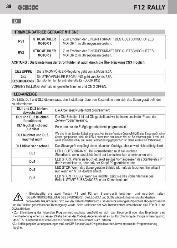
SEUIL AMPEREMETRIQUEMOTEUR 1
Tourner dans le sens horaire pour augmenter LA FORCE D’INTERVENTIONDU DISPOSITIF ANTI-ECRASEMENT MOTEUR 1
Tourner dans le sens horaire pour augmenter LA FORCE D’INTERVENTIONDU DISPOSITIF ANTI-ECRASEMENT MOTEUR 2
ATTENTION : le réglage des seuils ampèremétriques est également géré par le pontet CN3.
PARAMETRAGE PAR DEFAUT : trimmerss réglés à mi-course et CN 3 OUVERT.
Les LEDS DL1 et DL2 doivent informer l’installateur concernant l’état dans lequel se trouve l’unité
Le réglage du seuil AMPEREMETRIQUE varie de 2,5A à 5,5A
Le réglage du seuil AMPEREMETRIQUE varie de 3A à 7,5A(recommandé pour les opérateurs GiBiDi FLOOR 812)
Le temps de service n’a pas été programmé.
Le Dip 1 est sur ON et on est en phase de programmation des temps.
LED PHOTO. Dans le cadre d’un fonctionnement normal elle doit être allumée.Elle s’éteint lorsque le faisceau d’action des cellules photoélectriques est interrompu.LED START. Lorsqu’elle est allumée, elle signale la présence de la commandeSTART ou la pression sur la touche P2.LED STOP. Lorsque l’unité est en fonction, elle doit être allumée.Elle ne s’éteint que lorsque la commande STOP intervient.
LED START PED. Lorsqu’elle est allumée, elle signale la présence de lacommande START FONCTION PIETON.
Seul le temps de service fonction piéton a été programmé.
L’unité est en train de recevoir un type de code reconnu mais qui n’a pas étémémorisé.
Phase d’auto-apprentissage ÉMETTEUR. Dans la version code AS04260 si l’unité n’a pasd’émetteurs mémorisés, la première fois que l’on entre en auto-apprentissage la LED 1 clignote4 fois pour indiquer qu’aucune télécommande n’est mémorisée. Ensuite elle s’allume fixement.
SEUIL AMPEREMETRIQUEMOTEUR 2
RV2
• Appuyer en même temps sur les deux touches P1 et P2 situées sur l’unité et les maintenir enfoncées (REINITIALISATION TOTALE DE LA MEMOIRE). Les LEDS DL1 et DL2 s’allument fixement puis s’éteignent pour indiquer que la procédure de réinitialisation totale de la mémoire a été complétée et que la position de grille fermée a été déterminée. Lorsqu’on relâche ces deux touches les LEDS DL1 et DL2 clignotent alternativement.
• Pour faciliter la phase suivante de programmation, il est conseillé de faire apprendre une télécommande à l’unité ou au récepteur (Voir apprentissage des codes). Dans le cas contraire, pour exécuter la programmation il faut donner la commande START au moyen de la fermeture du contact sur les bornes 3-4.
• Pour valider les ralentissements, il faut placer le DIP 3 sur ON avant de commencer la programmation.
27
F
F12 RALLY
(temps de service, temps de pause et temps de dephasage des portes)
Il faut faire apprendre au premier raccordement les temps de service à l’unité.Tant que la programmation des temps n’est pas effectuée la touche Start fonctionne seulement avec homme présent d’abord la porte 2 ralentit en fermeture jusqu’à la burée, puis la porte 1 elle aussi jusqu’à sa butée. Pendant cette opération le Stop et les cellules photoélectriques sont ignorés.
ATTENTION:- il faut utiliser les blocages mécaniques de fin de course;- la logique de programmation des temps prévoit que le moteur 2 arrive avant le moteur 1 sur le blocage
mécanique de fermeture.
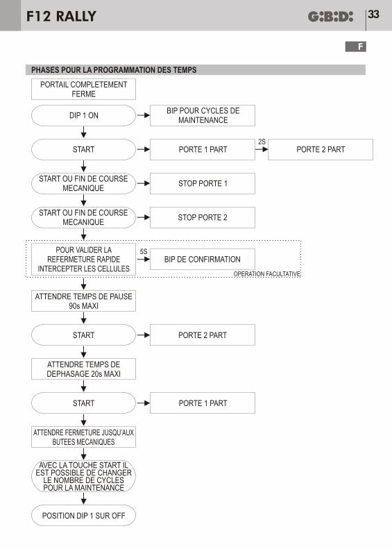
IMPORTANT: il faut toujours commencer cette phase à partir de la position portail complètement fermée.
Positionner le DIP 1 sur ON pour commencer la programmation : les LEDS DL1 et DL2 s’allument et l’unité émet des BIPS pour indiquer le nombre de cycles paramétrés pour la maintenance (voir paragraphe correspondant).
• Appuyer sur START : la porte 1 commence à s’ouvrir et après 2 secondes la porte 2 suit.• Lorsque la porte 1 arrive contre le butée mécanique d’ouverture elle s’arrête (S’il n’y a pas de butée mécanique,
appuyer sur START pour arrêter la porte 1 dans la position voulue).LA PORTE 1 S’ARRETE
• Lorsque la porte 2 arrive contre le butée mécanique d’ouverture, elle s’arrête (S’il n’y a pas de butée mécanique, appuyer de nouveau sur START pour arrêter la porte 2 dans la position voulue).
LA PORTE 2 S’ARRETE
• L’unité commence à compter le temps de pause (90 secondes maxi).• Lorsque le temps de pause désiré est écoulé, appuyer sur START.LA PORTE 2 COMMENCE A SE FERMER
• L’unité commence à compter le temps de déphasage en fermature (20 secondes maxi).• Lorsque le temps de déphasage désiré est écoulé, appuyer sur START.LA PORTE 1 COMMENCE A SE FERMER
• L’unité n’accepte pas d’autres commandes jusqu’à l’arrêt des 2 portes, qui s’effectue lorsque la butée mécaniques de fermeture est atteinte.
• Replacer le DIP1 sur OFF.
Si l’opération de programmation ne s’est pas bien déroulée à cause de l’intervention de la protection anti-écrasement, tourner les trimmers RV1 et RV2 dans le sens horaire et, en replaçant le DIP 1 sur ON, répéter les opérations de programmation (la réinitialisation de la mémoire n’est pas nécessaire). Si la grille est restée ouverte sans avoir mémorisé le temps de service, il est possible de ramener cette dernière en position de fermeture, en appuyant sur le Poussoir START et en le maintenant enfoncé.
PROGRAMMATION DES TEMPS
.
28
F
F12 RALLY
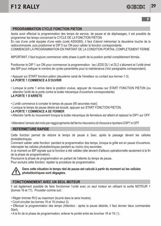
Après avoir effectué la programmation des temps de service, de pause et de déphasages, il est possible de programmer les temps concernant le CYCLE DE LA FONCTION PIETON.En cas d’une unité équipée d’une radio (code AS04260), il faut d’abord mémoriser la deuxième touche de la radiocommande, puis positionner le DIP 5 sur ON pour valider la fonction correspondante.COMMENCER LA PROGRAMMATION EN PARTANT DE LA CONDITION PORTAIL COMPLETEMENT FERME.IMPORTANT: il faut toujours commencer cette phase à partir de la position portail complètement fermée.
Positionner le DIP 1 sur ON pour commencer la programmation : les LEDS DL1 et DL2 s’allument et l’unité émet des BIP pour indiquer le nombre de cycles paramétrés pour la maintenance (Voir paragraphe correspondant).
• Appuyer sur START fonction piéton (deuxième canal de l’émetteur ou contact aux bornes 1-3).LA PORTE 1 COMMENCE A S’OUVRIR
• Lorsque la porte 1 arrive dans la position voulue, appuyer de nouveau sur START FONCTION PIETON (ou attendre l’arrêt de la porte contre la butée mécanique d’ouverture correspondante).
LA PORTE 1 S’ARRETE
• L’unité commence à compter le temps de pause (90 secondes maxi).• Lorsque le temps de pause désiré est écoulé, appuyer sur START FONCTION PIETON.LA PORTE 1 COMMENCE A SE FERMER• Attendre l’arrêt du mouvement lorsque la butée mécanique de fermeture est atteint et replacer le DIP1 sur OFF.
• Attendere l’arresto del moto per raggiungimento del fermo meccanico di chiusura e riportare il DIP1 in OFF
Cette fonction permet de réduire le temps de pause à 3sec. après le passage devant les cellules photoélectriques.Comment valider cette fonction: pendant la programmation des temps, lorsque la grille est en pause d'ouverture, intercepter les cellules photoélectriques pendant au moins cinq secondes.A ce moment un BIP signale que la fonction a été validée (elle devient d'ailleurs opérationnelle seulement à la fin de la phase de programmation).Poursuivre la phase de programmation en partant de l'attente du temps de pause.Pour excluire cette fonction: répéter la procédure de programmation.
Dans cette situation le temps réel de pause est calculé à partir du moment où les cellulesphotoélectriques sont dégagées.
Il est également possible de faire fonctionner l’unité avec un seul moteur en utilisant la sortie MOTEUR 1 (bornes 16 et 17). Procéder comme suit :
• Régler trimmer RV2 au maximum (tourné dans le sens horaire).• Court-circuiter les bornes 18 et 19 (moteur 2).• Effectuer la programmation des temps (Attention : après la pause désirée, il faut donner deux commandes Start).• A la fin de la phase de programmation, enlever le pontet entre les broches 18 et 19 ( !).
PROGRAMMATION CYCLE FONCTION PIETON
REFERMETURE RAPIDE
FONCTIONNEMENT AVEC UN SEUL MOTEUR
29
F
F12 RALLY
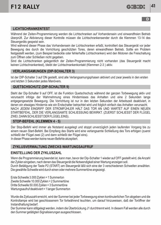
Un contrôle est effectué, pendant la phase de programmation des temps, sur la présence et le bon fonctionnement des cellules photoélectriques. Pour valider ce type de contrôle les émetteurs des cellules photoélectriques doivent être alimentés par les bornes 13-14 de l’unité.Si pendant cette phase la présence des cellules photoélectriques est confirmée, avant chaque mouvement de la grille protégée par le dispositif, l’unité en contrôle le bon fonctionnement et en cas de problèmes (par exemple cellules photoélectriques actionnées ou en panne) l’autorisation d’ouverture et de fermeture n’est pas fournie aux moteurs.Lorsque les cellules photoélectriques ne sont pas présentes lors de la programmation des temps l’unité n’effectue pas le contrôle (test cellules), mais le contact de la cellule (bornes 2-3 ) reste actif.
Si le DIP3 est sur ON les phases de ralentissement sont validées, respectivement pendant les premières et les 3 dernières secondes de chaque manoeuvre.
Si le Dip 9 est sur OFF la fonction anti-écrasement est activée pendant tout le mouvement de la grille provoquant ainsi, suite à l'interception d'un obstacle, l'arrêt et la reprise du mouvement dans le sens inverse pendant 2 secondes. Le dispositif est désactivé uniquement pendant les dernières secondes du temps de service, pendant lesquelles un éventuel obstacle est considéré comme une butée et entraîne donc simplement l'arrêt.APRES CHAQUE INTERVENTION DES SEUILS AMPEREMETRIQUES, LA GRILLE S’ARRETE ET ATTEND UNE NOUVELLE COMMANDE START,QUI EN DETERMINE LA FERMETURE RALENTIE (FERME D’ABORD LA PORTE DEUX, PUIS LA PORTE UN).
La commande STOP est toujours interprétée comme une urgence et arrête immédiatement toute opération en cours jusqu’à une nouvelle commande START.A l’arrivée de la commande START on aura une fermeture ralentie de la grille (ferme d’abord la porte deux (2), puis la porte un).
A la fin de la phase de programmation, avant de repositionner le Dip 1 sur OFF, il est possible de sélectionner le nombre de cycles terminés après lesquels l'unité signale la demande de maintenance.Il est possible de choisir parmi 3 seuils différents en appuyant sur la touche P2 (START) située sur l’appareil.Le seuil choisi est signalé par un ou plusieurs bips sonores.
Premier seuil 3.000 cycles = 1 BipDeuxième seuil 10.000 cycles = 2 BipsTroisième seuil 50.000 cycles = 3 BipsDemande de Maintenance désactivée = 1Bip long
Lorsque le nombre de cycles est atteint, le bip sonore commence à émettre un son continu à chaque mouvement de la grille et le voyant lumineux reste allumé fixe lorsque la grille est fermée pour signaler qu’une opération de maintenance périodique doit être effectuée sur l’automation.Le buzer peut être désactivé en coupant le pontet Jl. Dans ce cas, tous les signaux fournis au moyen du buzer seront exclus.
30
F
F12 RALLY
Pour réinitialiser le compteur du nombre de cycles, procéder comme suit:• Couper le courant sur l'unité. Déconnecter également la batterie, s'il y en a une• Réaliser un pontet sur CN4 broches 3 et 4• Remettre l'unité sous tension: le buzer sonore émettra des sons intermittents• Enlever le pontet situé sur CN4. A ce moment là les conditions initiales sont rétablies et l'unité exigera de nouveau
l'intervention pour la maintenance lorsque les manoeuvres paramétrées seront atteintes.• Pour exclure définitivement la sonnerie, il est possible de couper le cavalier JP1
Appuyer sur la touche PI (LEARN). La LED DL1 s'allume pour signaler que le récepteur est prêt à apprendre une télécommande,indifféremment DIP ou Rolling-Code (reconnaissance automatique du type de code). Après avoir appris un type de code, le système acceptera uniquement cette famille de codes, c'est-à-dire que si le premier est Rolling tous les autres devront être Rolling.Maintenant il est possible d'appuyer sur la première touche d'un Emetteur (ou la 2ème - Sème ou 4ème). Lorsque le code est appris, le récepteur donne une commande à l'unité. Sans appuyer de nouveau sur la touche PI, il est possible d'apprendre les autres télécommandes de la même famille et ainsi de suite jusqu'à l'apprentissage de toutes les télécommandes. Après avoir appris la dernière télécommande, attendre que la LED DL1 s'éteigne (environ 6 secondes) indiquant que le système a quitté l'apprentissage émetteur et qu'il est prêt à fonctionneren mode normal.En cas d'erreur réinitialiser la mémoire des codes, en appuyant sur la touche PI (la LED DL1 s'allume) et en la maintenant pressée tant que la LED DL1 ne s'éteint pas. Lorsqu'on relâche la touche la LED DL1 clignote une fois (pour indiquer que la mémoire est vide) puis s'allume de nouveau et le système est prêt pour apprendre de nouveau une télécommande (indifféremment code DIP ou Rolling-Code).
L’unité dans la version code AS04260 comprend déjà le Module radio 433 Mhz et la DECODIFICATION (Codes DIP28bits, à DIP 12bits,Rolling-code). Au maximum 200 codes différents mémorisables.
Après avoir mémorisé une télécommande, en mode Manuel (en appuyant sur la touche S1), il est possible de valider l’auto-apprentissage d’autres télécommandes de la même famille sans accéder à l’unité.Prés da la centrale appuyer en même temps, pendant 2 secondes, sur les touches 1 et 2 déjà apprises de l’émetteur, puis appuyer sur la touche d’une nouvelle télécommande pour l’apprendre automatiquement
II est possible d'appliquer l'alimentation de secours pour le fonctionnement de l'opérateur sans tension sur le secteur de 230 Vac.Au cours du fonctionnement exclusivement à l'aide d'une alimentation de secours, l'opérateur s'avère plus lent.Cette alimentation doit être connectée aux bornes CN11 (pôle positif), et CN10 (négatif).Batterie conseillée 12Vcc 1,9-2 Ah.
ATTENTION: pendant le fonctionnement avec une batterie tampon, la fonction anti-écrasement est exclue automatiquement et le clignotant signale cette condition par un clignotement plus lent.
REMISE
MODULE RADIO
APPRENTISSAGE DES CODES
APPRENTISSAGE TELECOMMANDES ROLLING-CODE SANS ACCEDER L’UNITE
ALIMENTATION DE SECOURS
31
F
F12 RALLY
Avant chaque montage ou intervention de maintenance, il faut s’assurer que le courant a été coupé.N’utiliser que des accessoires et des pièces détachées Gi.Bi.Di.
ANOMALIES CAUSES POSSIBLES et SOLUTIONS
LEDS rouges DL1 et DL2 allumées Unité en phase de programmation. Placer le DIP 1 sur OFF.
Contrôler que l’antenne est placée correctement (gaine borne 20, âmeborne 21 si appareil avec radio à bord, code AS04260). Si l’on utilise unrécepteur à enclenchement (code AU01710) l’antenne doit être connectéeaux bornes se trouvant sur le récepteur.Contrôler qu’aucune source parasitaire ponts radio ne se trouve àproximité, ni des parasites en limitant la portée.
Contrôler que les trimmers RV1 et RV2 ne sont pas complètementtournés dans le sens antihoraire.
Contrôler que les trimmers RV1 et RV2 ne sont pas complètementtournés dans le sens antihoraire.
Contrôler que les cellules photoélectriques sont connectées correctementContrôler le fusible F2 ( 10 A).
Contrôler que l’entrée STOP est reliée à une touche normalement ferméeou que le pontet a été réalisé entre les bornes 5 et 6 (ATTENTION : ’intervention du STOP entraîne un arrêt de fonctionnement et NON de sécurité).
Contrôle des codes maximums mémorisables (200).Vérification si l’on apprend les télécommandes de la même famille dupremier : DIP- SWITCH ou ROLLING. Contrôler que la fréquence de laradiocommande est la même que celle du récepteur.
Contrôler que les LEDS rouges DL5 et DL3 sont allumées, puis vérifier lebon fonctionnement des cellules photoélectriques.
L’opérateur n’ouvre oune ferme pas
LED rouge DL5 éteinte
L’émetteur a une faible portée
La carte n’apprend pas le codeémetteur
Ne se referme pas aprèsun temps deservice
En appuyant sur la 2ème touchede la télécommande la fonction
piéton ne s’effectue pas
LED rouge DL3 éteinte
Pendant que l’on effectue le câblage et/ou l’installation du MODULE RADIO l’appareil ne doit pas être sous tension.
L’utilisation de cet appareil doit respecter rigoureusement les indications fournies par le constructeur, sous peine d’annulation de la garantie.La mise en place et/ou la maintenance doit être effectuée uniquement par un personnel qualifié et conformément aux dispositionsréglementaires en vigueur.
Le constructeur décline toute responsabilité pour d’éventuels dommages causés par une mauvaise utilisation et/ou absurde.Gi.Bi.Di. se réserve le droit, à tout moment et sans aucun préavis, d’apporter des modifications dans le but d’améliorer le produit.
SOLUTION DES ANOMALIES
32
F
F12 RALLY
PORTAIL COMPLETEMENTFERME
DIP 1 ONBIP POUR CYCLES DE
MAINTENANCE
PORTE 1 PART PORTE 2 PART
PORTE 1 PART
PORTE 2 PART
STOP PORTE 1
STOP PORTE 2
BIP DE CONFIRMATION
OPERATION FACULTATIVE
START
START OU FIN DE COURSEMECANIQUE
START OU FIN DE COURSEMECANIQUE
POUR VALIDER LAREFERMETURE RAPIDE
INTERCEPTER LES CELLULES
ATTENDRE TEMPS DE PAUSE90s MAXI
START
START
ATTENDRE TEMPS DEDEPHASAGE 20s MAXI
ATTENDRE FERMETURE JUSQU’AUXBUTEES MECANIQUES
AVEC LA TOUCHE START ILEST POSSIBLE DE CHANGER
LE NOMBRE DE CYCLESPOUR LA MAINTENANCE
POSITION DIP 1 SUR OFF
2S
5S
PHASES POUR LA PROGRAMMATION DES TEMPS
33
F
F12 RALLY
Déclaration de conformité CELa société:
Via Abetone Brennero, 177/B,
46025 Poggio Rusco (MN) ITALY
Déclare que les produits:
APPAREIL ÉLECTRONIQUE F12 RALLY
sont en conformité avec les exigences des Directives CEE:
•
• Directive EMC 2004/108/CE et ses modifications;
et que les normes harmonisées suivantes ont été appliquées:
•
•
Date 16/07/08
GI.BI.DI. S.r.l.
Directive LVD 2006/95/CE et ses modifications;
EN60335-1
EN61000-6-2, EN61000-6-3
Ammistratore DelegatoOliviero Arosio
34
F
F12 RALLY
INSTALLATION
Verwenden Sie Drüsen ausreichen, um die ordnungsgemäße mechanische Verbindung von Kabel-und den Schutz box Grad IP55 (2)
TECHNISCHE MERKMALE
TECHNISCHE DATEN / FUNKTIONEN
Es hat eine komplette Palette von Funktionen (Wohnblock, Schrittbetrieb, Schrittbetrieb mit Wiederschließung, Fußgänger, Fußgänger mit Wiederschließung, Druckstoß, Quetschschutz und Verlangsamungen) und Einstellungen (Arbeitszeit, Arbeitszeit Fußgänger, Pausezeit, Phasenverschiebungszeit und Stromschwelle).Dank seiner Optionen ist es sehr vielseitig (Verlangsamungen beim Öffnen und Schließen, elektronischer Quetschschutz, Kontrolle der Lichtschrankenfunktionen, Anzeigelampe Tor offen, Funk an Bord oder zum Einstecken).Die herausziehbaren Klemmen und Siebdrucke auf der gedruckten Schaltung mit Angabe der Anschlüsse und Funktionen machen die Installation leicht.
F12 RALLY/AS04220
Elektronisches Gerät für die Automatisierung von einemoder zwei 12V-Antrieben für Flügeltore
1 o 2
12 Vdc 8W max
12Vdc 2W max
12Vdc 15W max
-20°C +60°C
Stromversorgung TX der Lichtschranken für TEST
90s max
12 Vdc
35
D
F12 RALLY
Gerät
Typ
Stromversorgung
Anzahl Motoren
Stromversorgung Antrieb
Blinklicht
Stromversorgung Zubehörteile
Funkempfänger
Einsatztemperatur
Laufzeit
2
zum Aufstecken
230 VAC einphasig 50/60 Hz
F12 RALLY36
D
WARNUNGEN FÜR DEN VERWENDER
WARNUNGEN FÜR DIE INSTALLATION
Bei Pannen oder Betriebsstörungen die Stromversorgung oberhalb des Geräts abtrennen und den Kundendienst verständigen. In regelmäßigen Abständen die Betriebstüchtigkeit der Sicherheitsvorrichtungen prüfen.Reparaturen müssen von Fachkräften mit zertifizierten Originalersatzteilen durchgeführt werden.Das Produkt darf nicht von Kindern bzw. Personen mit eingeschränkten körperlichen, selligen bzw. Sinnes- Eigenschaften benutzt werden. Dies gilt auch für nicht beauftragte Personen ohne Erfahrung, ohne dasws sie dazu geschult wurden.
• Bevor die Installation in Angriff genommen wird, ist vor der Anlage ein bei max. 10A ansprechender Thermomagnet - oder Differentialschalter zu installieren. Der Schalter muss die allpolige Trennung der Kontakte mit einer Öffnungsweite von mindestens 3 mm garantieren.
• Zur Vermeidung von Störungen sind Leistungskabel (Mindestdurchmesser 1,5mm²) von Signalkabeln (Mindestdurchmesser 0,5 mm²) zu differenzieren und stets getrennt zu halten.
• Die Verbindungen ausführen, wobei die folgenden Tabellen und der beigefügte Siebdruck zu beachten sind. Besonders darauf achten, dass alle Vorrichtungen, die denselben N.C. (normalerweise geschlossenen) Eingang teilen, hintereinander geschaltet und alle Vorrichtungen, die denselben N.O. (normalerweise offenen) Eingang teilen, parallel geschaltet werden. Falsche Installation oder fehlerhafte Verwendung des Produkts können die Anlagensicherheit beeinträchtigen.
• Sämtliche in der Verpackung enthaltenen Materialien dürfen keinesfalls in der Reichweite von Kindern aufbewahrt werden, da es sich um potentielle Gefahrenquellen handelt.
• Der Hersteller weist jede Haftung für die Funktionstüchtigkeit der Automatisierung von sich, falls nicht die von ihm selbst hergestellten bzw. die für die geplante Anwendung passenden Komponenten und Zubehörteile verwendet werden.
• Nach Abschluss der Installation stets sorgfältig den korrekten Betrieb der Anlage und der verwendeten Vorrichtungen überprüfen.
• Diese Gebrauchsanweisung wendet sich an Fachkräfte, die zur Installation von "unter Spannung stehenden Geräten" befugt sind, daher werden ausreichende Fachkenntnisse im Sinne einer ausgeübten Berufstätigkeit sowie die Einhaltung und Kenntnis der geltenden Normen vorausgesetzt
• Die Wartung hat durch Fachpersonal zu erfolgen.• Vor Ausführung von Reinigungs- oder Wartungsvorgängen das Gerät von der Stromversorgung trennen. • Das hier beschriebene Gerät darf ausschließlich für den Zweck verwendet werden, für den es entwickelt wurde:• Die Endeinsetzung überprüfen und sich vergewissern, dass alle Sicherheitsschritte unternommen wurden.• Andere als die hier vorgesehenen Verwendungs- und Einsatzbereiche des Produkts wurden vom Hersteller nicht
erprobt, daher stehen derartige Anwendungen unter der ausschließlichen Haftung des Installateurs.• Die Automatisierung mit gut sichtbaren Hinweisschildern signalisieren.• Den Verwender darauf hinweisen, dass Kinder oder Tiere nicht im Torbereich spielen, bzw. sich dort aufhalten dürfen.• Gefahrenstellen sind angemessen zu schützen (z.B. durch Verwendung einer mit Sensoren besetzten Leiste).
ACHTUNG! WICHTIGE SICHERHEITSHINWEISE.Aus Sicherheitsgründen ist es sehr wichtig folgenden Hinweisen zu folgen.Die vorliegende Betriebsanleitung aufbewahren.
Aktiviert die Verlangsamungen beim Starten und Beenden jedes Manövers.
Aktiviert ein 3 Sekunden langes Vorblinken, das jeder Bewegungsphase vorausgeht.
Aktiviert die ÖFFNUNG für Fußgänger mit dem zweiten Kanal des Senders (nur Version mit Empfänger an Bord)
Lichtschrankeneingang ( Klemmen 2-3), aktiv nur beim Schließen mit Stoppen und Umkehrung der Bewegung.
NICHT VERWENDET, AUF OFF LASSEN.
Aktivierung der automatischen Wiederschließung am Ende der gespeicherten Pausezeit (max. 90 Sekunden)
Aktiviert die Funktion WOHNBLOCK. Ein Start öffnet und es werden keine weiterenSTART-Befehle bei der Öffnung akzeptiert. Bei PAUSE wird durch einen START diePausezeit neu geladen. Beim Schließen stoppt ein START und öffnet wieder.
Lichtschrankeneingang (Klemmen 2-3), aktiv beim Öffnen sowie beim Schließen.Beim Öffnen wird die Bewegung angehalten und erst wenn der Kontakt frei ist, er folgt die Öffnung.Beim Schließen wird gestoppt und nach 1s er folgt die Umkehrung der Bewegung.
Aktiviert die Funktion DRUCKSTOSS, wobei es sich um einen kurzen Schließungsschub vorder Öffnung handelt, um die Auslösung des Schlosses zu erleichtern.
Die Einstellung der Dip-Schalter hat bei nicht gespeistem Steuergerät zu erfolgen.VOREINSTELLUNG: Dip 1 – Dip 2 - Dip 4 – Dip 8 - Dip 9 – Dip 10 = OFF
Schließt die Funktion QUETSCHSCHUTZ aus. Ein Hindernis während der Torbewegungwird als Endschalter betrachtet.
Aktiviert die Funktionen SCHRITTBETRIEB (ein Start-Befehl ÖFFNET, ein zweiter Befehl STOPPT,ein dritter Befehl SCHLIESST, der nächste Befehl STOPPT) oder SCHRITTBETRIEB mitAUTOMATISCHER WIEDERSCHLIESSUNG, je nachdem wie der DIP-Schalter 7 eingestellt ist.
FUNKTIONEN
Anhand der Dip-Schalter verrichtet das Steuergerät folgende Funktionen:
DIP1 ON
OFF
OFF
ON
ON
ON
ON
ON
ON
ON
OFF
ON
ON
DIP1
DIP2
DIP6
DIP8
DIP9
DIP2
DIP3
DIP4
DIP5
DIP6
DIP10
DIP7
ELEKTROANSCHLÜSSE: KLEMMENBRETTER
F12 RALLY38
D
LED-ANZEIGE
TRIMMER-BATRIEB GEPAART MIT CN3
RV1
CN3 OFFEN
CN3GESCHLCHOSSEN
DL1 und DL2 blinkenabwechselnd
DL1 und DL2 leuchtenfortwährend
DL3
DL4
DL5
DL6
DL1 leuchtet nicht undDL2 blinkt
DL1 leuchtet und DL2leuchtet nicht
DL1 blinkt sehr schnell
STROMFÜHLERMOTOR 1
Zum Erhöhen der EINGRIFFSKRAFT DES QUETSCHSCHUTZESMOTOR 1 im Uhrzeigersinn drehen.
Zum Erhöhen der EINGRIFFSKRAFT DES QUETSCHSCHUTZESMOTOR 2 im Uhrzeigersinn drehen.
ACHTUNG : Die Einstellung der Stromfühler ist auch durch die Überbrückung CN3 möglich.
VOREINSTELLUNG: Auf halb eingestellte Trimmer und CN 3 OFFEN.
Die LEDs DL1 und DL2 dienen dazu, den Installateur über den Zustand, in dem sich das Steuergerät befindet,zu informieren:
Die STROMFÜHLER-Regelung geht von 2,5A bis 5,5A.
Die STROMFÜHLER-REGELUNG geht von 3A bis 7,5A(Empfohlen für Torantriebe GiBiDi FLOOR 812)
Die Arbeitszeit wurde nicht programmiert.
Der Dip-Schalter 1 ist auf ON gestellt und wir befinden uns in der Phase derZeiten-Programmierung.
LED LICHTSCHRANKE. Bei Normalbetrieb muß sie leuchten.Sie erlischt, wenn das Lichtbündel der Lichtschranken unterbrochen wird.LED START. Wenn sie leuchtet, zeigt sie das Vorhandensein des Startbefehls inder Klemmleiste an, oder daß der Knopf P2 gedrückt wurde.LED STOP. Wenn das Steuergerät in Betrieb ist, muß sie leuchten. Sie erlischtnur, wenn ein STOP-Befehl erfolgt.
LED START FUSSG. Wenn sie leuchtet, zeigt sie das Vorhandensein desBefehls START FUSSGÄNGER in der Klemmleiste an.
Es wurde nur die Fußgängerarbeitszeit programmiert.
Das Steuergerät empfängt einen erkannten Codetyp, aber er wird nicht selbstgelernt.
Wir sind in der Sender-Selbstlernphase. Hat bei der Version Code AS04260 das Steuergerät keineSender gespeichert, blinkt die LED 1, wenn man zum ersten Mal auf Selbstlernen geht, 4 mal undweist somit darauf hin, daß keine Fernbedienung gespeichert ist. Dann leuchtet sie fortwährend.
STROMFÜHLERMOTOR 2
RV2
• Gleichzeitig die zwei Tasten P1 und P2 am Steuergerät betätigen und gedrückt halten (GESAMTRÜCKSTELLUNG DES SPEICHERS). Die LEDs DL1 und DL2 leuchten fortwährend auf und gehen dann wieder aus, um darauf hinzuweisen, daß das Verfahren zur Gesamtrückstellung des Speichers abgeschlossen ist
und die Position geschlossenes Tor festgelegt wurde. Beim Loslassen der zwei Tasten werden abwechselnd die LEDs DL1 und DL2 aufblinken.• Zur Erleichterung der folgenden Programmierungsphase empfiehlt es sich, das Steuergerät oder den Empfänger eine
Fernbedienung lernen zu lassen. (Siehe Lernen der Codes). Anderenfalls ist es zur Durchführung der Programmierung nötig, den START-Befehl durch Schließen des Kontaktes an den Klemmen 3-4 zu erteilen.
• Zur Befähigung der Verlangsamungen muß der DIP-Schalter 3 auf ON gestellt werden, bevor man mit der Programmierung beginnt.
F12 RALLY 39
D
(arbeitszeit, pausezeit und phasenverschiebungszeit flügel)
Beim ersten Anschluß muß man das Steuergerät die Arbeitszeiten selbstlernen lassen.Bis die Programmierung der Zeiten erfolgt, funktioniert die Start Taste nur mit Totmannfunktion, um zuerst den Flügel 2 beim Schließen verlangsamt bis zum Endschalter zu bewegen. Dann wird auch der Flügel 1 bis zu seinem Endschalter gehen. Während dieses Vorgangs werden Stop und die Lichtschranken außer acht gelassen.
ACHTUNG:- es ist erforderlich, die mechanischen Feststellvorrichtungen Endschalter zu verwenden;- die Logik der Zeitenprogrammierung sieht vor, dass der Motor 2 vor dem Motor 1 an der mechanischen
Feststellvorrichtung Schließen ankommt.
WICHTIG: Diese Phase stets von der Position vollkommen geschlossenes Tor beginnen.
Zum Beginnen der Programmierung den DIP-Schalter 1 auf ON stellen. Die LEDs DL1 und DL2 leuchten auf und das Steuergerät wird Summertöne abgeben und somit auf die eingestellte Anzahl der Zyklen, nach denen eine Wartung erforderlich ist, hinweisen (siehe bezüglicher Abschnitt).
• Auf Start drücken: Der Flügel 1 beginnt, sich zu öffnen und nach 2 Sekunden auch der Flügel 2.• Wenn der Flügel 1 am mechanischen Öffnungsendanschlag angekommen ist, hält er an (fehlt der mechanische Endanschlag, zum Stoppen des Flügels 1 in der gewünschten Position auf Start drücken).FLÜGEL 1 HÄLT AN.
• Wenn der Flügel 2 am mechanischen Öffnungsendanschlag angekommen ist, hält er an (fehlt der mechanische Endanschlag, zum Stoppen des Flügels 2 in der gewünschten Position erneut auf Start drücken).FLÜGEL 2 HÄLT AN.
• Das Steuergerät beginnt, die Pausezeit zu zählen (max. 90 Sekunden).• Wenn die gewünschte Pausezeit abgelaufen ist, auf START drücken.FLÜGEL 2 SETZT SICH ZUR SCHLIESSUNG IN BEWEGUNG
• Das Steuergerät beginnt, die Phasenverschiebungszeit zu zählen (max. 20 Sekunden).• Wenn die gewünschte Phasenverschiebungszeit abgelaufen ist, auf START drücken.FLÜGEL 1 SETZT SICH ZUR SCHLIESSUNG IN BEWEGUNG
• Bis zur Anhalten der 2 Flügel, das infolge der Ankunft an den zwei zutreffenden mechanischen Schließungsendschaltern erfolgt, akzeptiert das Steuergerät keine Befehle mehr.
• Den DIP-Schalter 1 auf OFF stellen.
Falls der Programmierungsvorgang wegen Eingreifens des Quetschschutzes nicht mit günstigem Ausgang verlaufen ist, die Trimmer RV1 und RV2 im Uhrzeigersinn drehen, den Dip-Schalter 1 wieder auf ON stellen, die Programmierungsvorgänge wiederholen (eine Speicherrückstellung) ist nicht erforderlich. Sollte das Tor offen geblieben sein, ohne daß die Pausezeit gespeichert wurde, läßt sich das Tor durch Gedrückthalten der Taste START wieder in Schließungsposition bringen.
ZEITEN-PROGRAMMIERUNG.
.
Nachdem die Arbeits-, Pause- und Phasenverschiebungszeiten programmiert wurden, kann man die Zeiten für den FUSSGÄNGERZYKLUS programmieren.Im Falle eines Steuergeräts mit Funk an Bord (Code AS04260) muß zuerst die zweite Taste der Funksteuerung selbstgelernt werden, dann zur Aktivierung der bezüglichen Funktionen den Dip-Schalter 5 auf ON stellen.MIT DER PROGRAMMIERUNG AB DER BEDINGUNG VOLLKOMMEN GESCHLOSSENES TOR BEGINNEN.
WICHTIG: Diese Phase stets von der Position vollkommen geschlossenes Tor beginnen.
Zum Beginnen der Programmierung den DIP-Schalter 1 auf ON stellen: Die LEDs DL1 und DL2 leuchten auf und das Steuergerät wird Summertöne abgeben und somit auf die Anzahl der zur Wartung eingegebenen Zyklen verweisen (siehe bezüglicher Abschnitt).
• Auf Start Fußgänger drücken (zweiter Kanal des Senders oder Kontakt an den Klemmen 1-3)DER FLÜGEL 1 BEGINNT, SICH ZU ÖFFNEN.
• Wenn der Flügel 1 die gewünschte Position erreicht hat, erneut auf START FUSSGÄNGER drücken (oder warten, bis der Flügel am mechanischen Öffnungsendanschlag ankommt).DER FLÜGEL HÄLT AN.
• Jetzt zählt das Steuergerät die Pausezeit (max. 90 Sekunden).• Nach Ablauf der gewünschten Pausezeit, auf START FUSSGÄNGER drücken.DER FLÜGEL 1 BEGINNT, SICH ZU SCHLIESSEN.
• Warten, bis die Bewegung aufgrund Ankunft am mechanischen Schließungsendanschlag gestoppt wird und den DIP-Schalter 1 wieder auf OFF stellen.
F12 RALLY40
D
Diese Funktion erlaubt die Verringerung der Pausezeit auf 3 Sekunden ab dem Eingreifen und der folgenden Befreiung der Lichtschranken.Aktivierung dieser Funktion: Während der Zeiten-Programmierung, wenn das Tor in der Öffnungspause ist, die Lichtschranken mindestens 5 Sekunden lang unterbrechen.Ein Summerton wird angeben, daß die Funktion aktiviert wurde (tatsächlich operativ wird sie erst nach Abschluß der Programmierungsphase).Die Programmierung beginnend ab dem Warten der Pausezeit fortsetzen.Ausschließung dieser Funktion: Das Programmierverfahren wiederholen.
In dieser Situation wird die wirkliche Pausezeit ab dem Moment berechnet, in dem dieLichtschranken frei werden.
Das Steuergerät kann durch Verwendung des Ausgangs MOTOR 1 (Klemmen 16 und 17) auch nur mit einem Motor betrieben werden.• Den Trimmer RV2 auf maximal einstellen (im Uhrzeigersinn drehen).• Die Klemmen 18 und 19 kurzschließen (Motor 2).• Die Zeiten-Programmierung vornehmen (Achtung: Nach der gewünschten Pause müssen zwei Startbefehle
gegeben werden).• Nach abgeschlossener Programmierung die zwischen den Stiften 18 und 19 gemachte Überbrückung
entfernen (!)
PROGRAMMIERUNG FUSSGÄNGERZYKLUS
SCHNELLE WIEDERSCHLIESSUNG
BETRIEB MIT NUR EINEM MOTOR
F12 RALLY 41
D
Während der Zeiten-Programmierung werden die Lichtschranken auf Vorhandensein und einwandfreien Betrieb überprüft. Zur Aktivierung dieser Kontrolle müssen die Lichtschrankensender durch die Klemmen 13-14 des Steuergeräts gespeist sein.Wird während dieser Phase das Vorhandensein der Lichtschranken erfaßt, kontrolliert das Steuergerät vor jeder Bewegung des durch die Vorrichtung geschützten Tores, deren einwandfreien Betrieb. Sollte ein Problem festgestellt werden, (zum Beispiel bedeckte oder fehlerhafte Lichtschranken) wird den Motoren die Freischaltung zum Öffnen oder Schließen nicht gegeben.Sind die Lichtschranken gelegentlich der Zeiten-Programmierung nicht vorhanden (das Steuergerät macht keinen Lichtschrankentest), bleibt der Lichtschrankenkontakt (Klemmen 2-3 ) aktiv.
Ist der DIP-Schalter 3 auf ON gestellt, sind alle Verlangsamungsphasen aktiviert und zwar jeweils in den ersten und letzten 3 Sekunden jedes Manövers.
Steht der Dip-Schalter 9 auf OFF, ist die Funktion Quetschschutz während der ganzen Torbewegung aktiv und verursacht infolge der Wahrnehmung eines Hindernisses das Anhalten und eine 2 Sekunden lange entgegengesetzte Bewegung. Die Vorrichtung ist nur in den letzten Sekunden der Arbeitszeit deaktiviert, in denen ein etwaiges Hindernis wie ein Endschalter betrachtet wird und folglich einfach das Anhalten verursacht.NACH JEDEM EINGRIFF DER STROMFÜHLER HÄLT DAS TOR AN UND WARTET AUF EINEN NEUEN STARTBEFEHL, DER DIE VERLANGSAMTE SCHLIESSUNG BEWIRKT. (ZUERST SCHLIESST DER FLÜGEL ZWEI, DANN SCHLIESST DER FLÜGEL EINS).
Der Stop-Befehl wird immer als Notstand ausgelegt und stoppt unverzüglich jeden laufenden Vorgang bis zu einem neuen Start-Befehl. Bei Empfang des Starts wird eine verlangsamte Schließung des Tors erfolgen (zuerst schließt der Flügel zwei (2) und dann schließt der Flügel eins).In dieser Phase werden keine neuen Befehle akzeptiert.
ZYKLUSVERWALTUNG ZWECKS WARTUNGSAUFRUF
LICHTSCHRANKENTEST
VERLANGSAMUNGEN (DIP-SCHALTER 3)
QUETSCHSCHUTZ (DIP-SCHALTER 9)
STOP-BEFEHL (KLEMMEN 4 - 5)
EINSTELLUNG DER ZYKLUSZAHL
Wenn die Programmierung beendet ist, kann man, bevor der Dip-Schalter 1 wieder auf OFF gestellt wird, die Anzahl der Zyklen eingeben, nach denen das Steuergerät die Notwendigkeit einer Wartung anzeigen soll.Durch Betätigung der Taste P2 (START) am Steuergerät läßt sich eine der 3 verschiedenen Schwellen anwählen. Die gewählte Schwelle wird durch einen oder mehrere Summertöne angezeigt.
Wurde die Zykluszahl erreicht, wird der Summer bei jeder Torbewegung einen kontinuierlichen Ton abgeben und die Kontrollampe wird bei geschlossenem Tor fortwährend leuchten, um darauf hinzuweisen, daß der Toröffner der Instandhaltung bedarf.Der Summer kann stillgelegt werden, indem die Überbrückung J1 durchtrennt wird. In diesem Fall werden alle durch den Summer getätigten Signalisierungen ausgeschlossen.
F12 RALLY42
D
Das Steuergerät ist bei der Version Code AS04260 bereits mit dem Funkmodul 433 Mhz ausgestattet und DECODIERT Codes DIP28bit, DIP 12bit, Rolling-code; es sind max. 200 verschiedene Codes speicherbar.
Zum Rückstellen des Zykluszählers wie folgt vorgehen:• Die Steuergerätspeisung unterbrechen. Falls vorhanden, auch die Batterie loslösen.• Eine Überbrückung an CN4 Stift 3 und 4 herstellen.• Die Speisung wieder einschalten: Der Summer wird aussetzende Töne abgeben.• Die Überbrückung von CN4A entfernen. Jetzt sind alle anfänglichen Bedingungen wieder hergestellt und das
Steuergerät wird beim Erreichen der eingegebenen Manöver erneut zur Wartung aufrufen.• Zur endgültigen Ausschließung des SUMMER-Tons die Überbrückung JP1 durchtrennen.
Nachdem man das System auf manuelle Weise (durch Betätigung der Taste S1) eine Fernbedienung lernen lies, kann das Selbstlernen weiterer Fernbedienungen derselben Familie ohne Zugriff auf das Steuergerät aktiviert werden.In Nähe des Steuergeräts hierzu gleichzeitig 2 Sekunden lang auf die Tasten 1 und 2 des bereits gelernten Senders drücken; betätigt man dann die Taste einer neuen Fernbedienung, wird diese selbstgelernt.
Damit der antrieb auch bei Ausfall der Netzspannung 230VW funktioniert, kann das Pufferbatterie angebracht werden. Bei ausschließlichem betrieb durch die Pufferbatterie läuft der antrieb etwas langsamer.Diese Batterie an den klemmen CN11 (Pluspole), und CN10 (Minuspole) anschließen.Empfohlene Batterie 12VDC 1,9-2 Ah.
ACHTUNG: Während der Funktion mit Pufferbatterie wird die Funktion Quetschschutz automatisch ausgeschlossen und das Blinklicht signalisiert diese Situation durch ein langsameres Blinken.
Die Taste P1 (LEARN) betätigen. Die LED DL1 wird aufleuchten und somit anzeigen, daß der Empfänger zum Lernen einer Fernbedienung bereit ist, egal ob mit DIP oder Rolling-Code (automatische Erkennung des Codetyps); nach dem Lernen eines Codetyps wird das System nur diese Codefamilie akzeptieren, sprich falls der erste ein Rolling-Code ist, müssen alle andere Rolling-Codes sein).Jetzt kann man auf die erste Taste eines Senders (oder die 2., 3. oder 4.) drücken. Bei gelerntem Code wird der Empfänger einen Befehl an das Steuergerät geben. Ohne erneute Betätigung der Taste P1 lassen sich weitere Fernbedienungen derselben Familie lernen und weiter so, bis alle Fernbedienungen gelernt wurden.Nach dem Lernen der letzten Fernbedienung muß man auf das Erlöschen der LED DL1 (circa 6 Sekunden) warten, wodurch angezeigt wird, daß das System vom Sender-Lernen abgesprungen und zum Normalbetrieb bereit ist. Ist ein Fehler unterlaufen, den Codespeicher rückstellen, indem man die Taste P1 (die LED DL1 leuchtet auf) so lange gedrückt hält, bis die LED DL1 erlischt.Beim Loslassen der Taste blinkt die LED DL1 1x auf (zur Anzeige, daß der Speicher leer ist) und leuchtet dann wieder und das System ist bereit, eine neue Fernbedienung zu lernen (egal ob mit DIP oder Rolling-Code).
ZYKLUSNULLSTELLUNG
FUNKMODUL
LERNEN DER CODES
PUFFERBATTERIE
LERNEN DER ROLLING-CODE FERNBEDIENUNGEN OHNE ZUGRIFF AUF DAS STEUERGERÄT
F12 RALLY 43
D
Vor jeder Montage oder Wartung sicherstellen, daß die Speisung unterbrochen wurde.Nur Originalzubehör und -ersatzteile von Gi.Bi.Di. verwenden.
STRÖRUNG MÖGLICHE URSACHE und ABHILFEN
Rote LEDs DL1 und DL2 leuchten. Das Steuergerät ist in der Programmierungsphase. Den Dip-Schalter 1 auf OFF stellen.
Überprüfen, ob die Antenne richtig positioniert ist (Geflecht Klemme 20 SeeleKlemme 21), falls es ein Gerät mit Funk an Bord ist, Code AS04260. BeiVerwendung des Steckempfängers (Code AU01710) ist die Antenne an denKlemmen an Bord des Empfängers anzuschließen).Sich vergewissern, daß in der Nähe keine Richtfunkverbindungen oderStörungen bestehen, die die Reichweite einschränken.
Überprüfen, daß die Trimmer RV1 und RV2 nicht ganz gegen Uhrzeigersinngedreht sind.
Überprüfen, daß der DIP-Schalter 5 auf ON ist und die Fußgängertaste derFernbedienungvorher gelernt wurde.
Überprüfen, daß die Lichtschranken richtig angeschlossen sind.Die Schmelzsicherung F2 ( 10 A) überprüfen.
Überprüfen, daß der STOP-Eingang an einer Ruhekontakttaste angeschlossen ist oderdie Überbrückung zwischen den Klemmen 5 und 6 gemacht wurde. (ACHTUNG : DasEingreifen von STOP verursacht einen Betriebsstopp aber keinen Sicherheitsstopp)
Überprüfung der maximal speicherbaren Codes (200).Überprüfen, daß Fernbedienungen derselben Familie der ersten gelerntwerden: DIP-SCHALTER oder ROLLING Überprüfung, daß die Frequenzder Funksteuerung dieselbe des Empfängers ist.
Überprüfen, daß die roten LEDs DL5 und DL3 leuchten und die Lichtschrankenauf ihren einwandfreien Betrieb kontrollieren.
Der Antrieb öffnet undschließt nicht.
Rote Led DL5 leuchtet nicht.
Der Sender hat wenigReichweite.
Die Platine lernt deSendercode nicht.
Keine Wiederschließungnach der Arbeitszeit.
Bei Betätigung der 2. Taste derFernbedienung wird die
Fußgängerfunktion nicht ausgeführt.
Rote Led DL3 leuchtet nicht.
Bei der Verkabelung oder dem Einbau des FUNKMODULS darf das Steuergerät nicht gespeist sein. Die Verwendung dieses Steuergeräts muß sich streng an die vom Hersteller erteilten
technischen Sicherheitsvorschriften halten, anderenfalls droht die Nichtigkeit der Grantiebedingungen.Die Installations- und/oder Wartungsarbeiten dürfen nur durch qualifiziertes Personal unter Einhaltung der geltenden gesetzlichen Bestimmungen erfolgen.
Der Hersteller kann nicht für Schäden verantwortlich betrachtet werden, die auf einen falschen und/oder unvernünftigen Gebrauchzurückzuführen sind.Die Firma Gi.Bi.Di. behält sich das Recht vor, jederzeit und ohne irgendeine Voranzeige Änderungen vorzunehmen, die der Optimierung des Produkts dienen.
ABHILFE BEI STÖRUNGEN
F12 RALLY44
D
PHASEN FÜR DIE ZEITEN-PROGRAMMIERUNG
GANZ GESCHLOSSENESTOR
DIP-SCHALTER 1 ONSUMMTERTON DER ZYKLUSZAHL
FÜR DEN WARTUNGSAUFRUF
FLÜGEL 1 STARTET FLÜGEL 2 STARTET
FLÜGEL 1 STARTET
FLÜGEL 2 STARTET
STOPP FLÜGEL 1
STOPP FLÜGEL 2
SUMMERTON ZURBESTÄTIGUNG
FREIWILLIGER VORGANG
START
START ODER MECHANISCHERENDANSCHLAG
START ODER MECHANISCHERENDANSCHLAG
ZUR AKTIVIERUNG DER SCHNELLENWIEDERSCHLIESSUNG DIE
LICHTSCHRANKEN UNTERBRECHEN
PAUSEZEIT ABWARTEN,MAX. 90 SEKUNDEN.
START
START
PHASENVERSCHIEBUNGSZEITABWARTEN, MAX. 20 SEKUNDEN
SCHLIESSUNG BIS ZU DEN MECHA-NISCHEN ENDANSCHLÄGEN ABWARTEN
MIT DER TASTE STARTKANN MAN DIE ANZAHL DER
ZYKLEN FÜR DENWARTUNGSAUFRUFÄNDERN
DEN DIP-SCHALTER AUFOFF STELLEN
2S
5S
F12 RALLY 45
D
CE-KonformitätserklärungDer Hersteller:
Via Abetone Brennero, 177/B,
46025 Poggio Rusco (MN) ITALY
Erklärt, dass die Produkte:
ELEKTRONIKGERÄT F12 RALLY
den folgenden CEE-Richtlinien entsprechen:
•
• EMV-Richtlinie 2004/108/CE und nachfolgende Änderungen;
und dass die nachfolgenden harmonisierten Vorschriften angewendet wurden:
•
•
Datum 16/07/08
GI.BI.DI. S.r.l.
LVD-Richtlinie 2006/95/CE und nachfolgende Änderungen;
EN60335-1,
EN61000-6-2, EN61000-6-3
Unterschrift des GeschäftsführersOliviero Arosio
F12 RALLY46
E
CARACTERÍSTICAS TÉCNICAS
CARACTERÍSTICAS TÉCNICAS / FUNCIONES
El equipo está completo para la gama de funcionamiento (comunitario, paso a paso, paso a paso con recierre, peatonal, peatonal con recierre, golpe de ariete, anti-aplastamiento y ralentizadores) y de regulaciones (tiempo de trabajo, tiempo de trabajo peatonal, tiempo de pausa, tiempo de desfase y umbral amperimétrico).Es versátil por sus opciones (ralentizadores en apertura y cierre, anti-aplastamiento electrónico, control de funcionamiento de fotocélulas, indicador de señalización de cancela abierta, radio a bordo o con enchufe).Es fácil de instalar gracias a los bornes extraíbles y a las serigrafías presentes en el circuito impreso, que indican conexiones y funciones.
F12 RALLY/AS04220
Equipo electrónico para la automatización de uno odos motores para cancelas de batiente de 12V
1 o 2
12 Vdc 8W max
12Vdc 2W max
12Vdc 15W max
-20°C +60°C
Alimentación TX fotocélulas para TEST
90s max
12 Vdc
INSTALACIÓN
Utilizar sujeta - cables adecuados a asegurar la correcta conexión mecánica del cablo y a mantener el grado de protección de la caja. (2)
Equipo
Tipo
Alimentación
N.º motores
Alimentación motor
Intermitente
Alimentación accesorios
Receptor radio
Temperatura de funcionamiento
Tiempo de trabajo
2
de enchufe
230Vac monofásica 50/60 Hz
F12 RALLY 47
E
ADVERTENCIAS PARA EL USUARIO
ADVERTENCIAS PARA LA INSTALACIÓN
En caso de averías o anomalías de funcionamiento, desconecte la alimentación aguas arriba del equipo y llame al servicio de asistencia técnica. Compruebe periódicamente que los dispositivos de seguridad funcionen correctamente. Cualquier reparación debe ser realizada por personal especializado y usando materiales originales y certificados. El producto no debe ser utilizado por niños o personas con reducidas capacidades físicas, sensoriales o mentales, o sin experiencia y conocimiento, a menos que no hayan sido correctamente instruidos. No acceder a la ficha para reglaciones y/o manutenciones.
• Antes de proceder con la instalación, hay que preparar aguas arriba de la instalación un interruptor térmico o diferencial con capacidad máxima de 10A. El interruptor debe garantizar la separación omnipolar de los contactos con una distancia de apertura mínima de 3 mm.
• Para evitar posibles interferencias, distinga y mantenga siempre separados los cables de potencia (sección mínima 1,5mm²) de los cables de señal (sección mínima 0,5mm²).
• Realice las conexiones consultando las siguientes tablas y la serigrafía adjunta. Preste suma atención a conectar en serie todos los dispositivos que deben conectarse a la misma entrada N.C. (normalmente cerrada) y, en paralelo todos los dispositivos que comparten la misma entrada N.A. (normalmente abierta).La instalación o utilización incorrecta del equipo puede afectar la seguridad del equipo.
• Todo material presente en el embalaje debe mantenerse fuera del alcance de los niños, ya que constituye una posible fuente de peligro.
• El fabricante declina toda responsabilidad relativa al funcionamiento correcto de la automatización si no se utilizan los componentes y accesorios originales específicamente destinados a la aplicación prevista.
• Al terminar la instalación, compruebe siempre con atención que el equipo y los dispositivos utilizados funcionen correctamente.
• Este manual de instrucciones está destinado a personas capacitadas para la instalación de bajo tensión". Por lo tanto, se requiere un buen conocimiento técnico, ejercido como profesión y “equipos respetando las normas vigentes.
• El mantenimiento debe ser realizado por personal capacitado.• Antes de realizar cualquier operación de limpieza o mantenimiento, desconecte el equipo de la red de alimentación eléctrica.
• El equipo descrito en este manual debe utilizarse exclusivamente para los fines previstos.• Verifiar el fin del utilizador final y asegurarse de tomar todas las seguridades necesarias• El uso de los productos y su destinación a usos no previstos no han sido experimentados por el fabricante, por lo que cualquier trabajo realizado queda bajo completa responsabilidad del instalador
• La automatización debe estar indicada por placas de advertencia bien visibles..• Avise al usuario que está prohibido dejar que niños o animales jueguen o se detengan en los alrededores de la cancela.• Proteja adecuadamente los puntos peligrosos (por ejemplo, usando una moldura sensible).
CUIDADO: IMPORTANTES INSTRUCCIONES DE SEGURIDAD.Es importante por la seguridad de las personas seguir estas instrucciones.Conservar el presente manual de instrucciones
1 Entrada START PEATONAL (N.A.) 11- 12 Contacto de relé libre (N.A.) para indicador
2 Entrada fotocélula (N.C.) 13- 14Salida 12 VDC para la alimentación de txfotocélulas, a utilizarse para la ejecución
del FOTOTEST (13 = positivo)
3 Común para Start PEATONAL y Fotocélula 14- 15Salida +12 VDC para intermitente
(15 = positivo)
4 Entrada START (N.A.) 16- 17 Salida motor1
(16 positivo en apertura)
6 Común para STOP y START 20 Tierra de antena
5 Entrada Stop (N.C.) 18- 19 Salida motor2
(18 positivo en apertura)
7 - 8
Salida +12 V CC para la alimentación deaccesorios. 7= POSITIVO. ATENCIÓN: paraefectuar el FOTOTEST, el TX de la fotocélula
Habilita los ralentizadores al inicio y al final de cada maniobra.
Habilita un pre-destello de 3 segundos que precede cada fase de movimiento.
Habilita la APERTURA peatonal con el segundo canal del TX (sólo para la versión con receptor a bordo)
Entrada fotocélulas (bornes 2-3) activa sólo en cierre con parada e inversión de la marcha.
NO UTILIZADO, MANTENER EN OFF
Habilitación del recierre automático después del tiempo de pausa memorizado (máx. 90 segundos).
Habilita la función COMUNITARIA. Un start abre y no se aceptan otros comandos deSTART en la apertura. En PAUSA, un START recarga el Tiempo de Pausa.En cierre, un START detiene y vuelve a abrir.
Entrada fotocélulas (bornes 2-3) activa sea en aper tura que en cierre. En aper tura, parada de la marchay aper tura sólo al liberarse el contacto. En cierre, parada y pausa de 1s antes de inver tir la marcha.
Habilita la función de GOLPE de ARIETE, que consiste en un breve movimiento de cierreantes de la apertura para facilitar el desenganche de la cerradura eléctrica.
La regulación de los dip se debe efectuar con la alimentación de la centralita desconectada.CONFIGURACIÓN POR DEFECTO: Dip 1 – Dip 2 - Dip 4 – Dip 8 - Dip 9 – Dip 10 = OFF
Excluye la función de ANTI-APLASTAMIENTO.Un obstáculo durante el movimiento de la cancela se considera un final de carrera.
Habilita las funciones de PASO A PASO (un comando de start ABRE, un segundocomando PARA un tercer comando CIERRA y el comando sucesivo DETIENE) oPASO A PASO con RECIERRE AUTOMÁTICO, de acuerdo a la posición del DIP7.
FUNCIONES
La centralita lleva a cabo las siguientes funciones mediante los Dip:
DIP1 ON
OFF
OFF
ON
ON
ON
ON
ON
ON
ON
OFF
ON
ON
DIP1
DIP2
DIP6
DIP8
DIP9
DIP2
DIP3
DIP4
DIP5
DIP6
DIP10
DIP7
CONEXIONES ELECTRICAS: TABLEROS DE BORNES
F12 RALLY48
E
SEÑALIZACIÓN LED
FUNCIONAMIENTO DEL TRIMMER EN COMBINACIÓN CON CN3
RV1
CN3 ABIERTO
CN3 CERRADO
DL1 y DL2 destellanalternativamente
DL1 y DL2 encendidos fijos
DL3
DL4
DL5
DL6
DL1 apagado y DL2 destella
DL1 encendido y DL2apagado
DL1 destella muyrápidamente
AMPERIMÉTRICAMOTOR 1
Girar en sentido horario para aumentar LA FUERZA DE INTERVENCIÓNDEL ANTI-APLASTAMIENTO MOTOR 1
Girar en sentido horario para aumentar LA FUERZA DE INTERVENCIÓNDEL ANTI-APLASTAMIENTO MOTOR 2
ATENCIÓN : la regulación de las amperimétricas se gestiona también desde el puente CN3.
CONFIGURACIÓN POR DEFECTO: trimmers regulados a mitad de la carrera y CN 3 ABIERTO.
Los leds DL1 y DL2 tienen la función de informar al instalador sobre el estado en que se encuentra la centralita.
La regulación AMPERIMÉTRICA varía de 2,5A a 5,5A
La regulación AMPERIMÉTRICA varía de 3A a 7,5A (Aconsejado para operadores GiBiDi FLOOR 812)
No se ha programado el tiempo de trabajo.
No se ha programado el tiempo de trabajo.
LED FOTO. Debe estar encendido durante el funcionamiento normal. Se apagacuando se interrumpe el haz de acción de las fotocélulas.LED START. Cuando está encendido indica la presencia del comando de STARTen los bornes o la pulsación del botón P2.LED STOP. Cuando la centralita está conectada, este led debe estar encendido.El led se apaga sólo cuando interviene un comando de STOP.
LED START PEAT. Cuando está encendido indica la presencia del comandode START PEATONAL en los bornes.
Se ha programado sólo el tiempo de trabajo peatonal.
La centralita está recibiendo un tipo de código reconocido pero que no seha autoaprendido.
Estamos en la fase de autoaprendizaje TX. En la versión AS04260, si la centralita no tienetx memorizados la primera vez que se entra en autoaprendizaje, el LED 1 destella 4 vecespara indicar que no hay telecomandos memorizados y luego se enciende fijo.
AMPERIMÉTRICAMOTOR 2
RV2
• Pulsar contemporáneamente las teclas P1 y P2 situadas en la centralita y mantenerlas pulsadas (REINICIO TOTAL DE LA MEMORIA).Los DL1 y DL2 se encienden fijos y luego se apagan para indicar que se ha completado el procedimiento de reinicio
total de la memoriay se ha determinado la posición de cancela cerrada. Al soltar las dos teclas, los leds DL1 y DL2 destellan alternativamente.• Para facilitar la fase de programación sucesiva, se aconseja que la central o el receptor aprendan un telecomando (Véase
autoaprendizaje códigos). En caso contrario, para llevar a cabo la programación es necesario dar un comando de START mediante el cierre del contacto en los bornes 3-4.
• Para habilitar los ralentizadores hay que poner en ON el DIP 3 antes de iniciar la programación.
F12 RALLY 49
E
(tiempo de trabajo, tiempo de pausa y tiempo de desfase de las puertas)
En la primera conexión, la centralita debe autoaprender los tiempos de trabajo.Hasta que no se efectúe la programación de tiempos, la tecla de Start funciona sólo con la presencia de un operario para mover primero la puerta 2 ralentizada en cierre hasta su final de carrera y después la puerta 1 hasta su final de carrera. Durante esta operación se ignoran el Stop y las fotocélulas.
ATENCIÓN:- es necesario usar bloqueos mecánicos de final de carrera;- la lógica de programación de los tiempos prevé que el motor 2 alcance el bloqueo mecánico antes que el
motor 1.
IMPORTANTE: iniciar esta fase siempre desde la posición de cancela cerrada.
Poner en ON el DIP 1 para iniciar la programación: los leds DL1 y DL2 se encienden y la centralita empieza a emitir un sonido de BIP para indicar el número de ciclos configurados para el mantenimiento (Véase párrafo correspondiente).
• Pulsar start: se empieza a abrir la puerta 1 y después de 2 segundos, también la puerta 2.• La puerta 1 se detiene cuando alcanza el bloqueo mecánico de apertura (Si no existe un bloqueo mecánico, pulsar
start para detener la puerta 1 en la posición deseada).LA PUERTA 1 SE DETIENE
• La puerta 2 se detiene cuando alcanza el bloque mecánico de apertura (Si no existe un bloqueo mecánico, pulsar nuevamente star t para detener la puerta 2 en la posición deseada).
LA PUERTA 2 SE DETIENE
• La centralita empieza a contar el tiempo de pausa (máx. 90 segundos).• Transcurrido el tiempo de pausa deseado, pulsar START.LA PUERTA 2 EMPIEZA A CERRARSE
• La centralita empieza a contar el tiempo de desfase (máx. 20 segundos).• Transcurrido el tiempo de desfase deseado, pulsar STARTLA PUERTA 1 EMPIEZA A CERRARSE
• La centralita no acepta otros comandos hasta la parada de ambas puertas, que se efectúa cuando éstas alcanzan sus respectivos bloqueos mecánicos de cierre.
• Volver a poner en OFF el DIP1.
Si no se logra efectuar la operación de programación debido a la intervención de la protección anti-aplastamiento, girar los trimmers RV1 y RV2 en sentido horario, poner nuevamente en ON el dip 1 y repetir las operaciones de programación (no es necesario reiniciar la memoria). Si la cancela ha quedado abierta sin haber memorizado el tiempo de trabajo, es posible llevarla nuevamente a la posición de cierre pulsando y manteniendo pulsado el Botón de START.
PROGRAMACIÓN DE TIEMPOS
F12 RALLY50
E
F12 RALLY 51
E
.
Después de haber efectuado la programación de los tiempos de trabajo, pausa y desfase, es posible programar los tiempos relativos al CICLO PEATONAL.En caso de centralita con radio a bordo (AS04260), primero hay que efectuar el autoaprendizaje de la segunda tecla del radiocomando y luego hay que poner el Dip 5 en ON para habilitar la relativa función.INICIAR LA PROGRAMACIÓN A PARTIR DE LA CONDICIÓN DE CANCELA COMPLETAMENTE CERRADA.
IMPORTANTE: iniciar esta fase siempre desde la posición de cancela cerrada.
Poner en ON el DIP 1 para iniciar la programación: los leds DL1 y DL2 se encienden y la centralita empieza a emitir un sonido de BIP para indicar el número de ciclos configurados para el mantenimiento (Véase párrafo correspondiente).
• Pulsar el start peatonal (segundo canal del TX o contacto en los bornes 1-3)LA PUERTA 1 EMPIEZA A ABRIRSE
• Cuando la puerta 1 llega a la posición deseada, pulsar nuevamente el START PEATONAL (o esperar a que la puerta se detenga al alcanzar su relativo final de carrera mecánico de apertura).
LA PUERTA 1 SE DETIENE
• La centralita empieza a contar el tiempo de pausa (máx. 90 segundos).• Transcurrido el tiempo de pausa deseado, pulsar el START PEATONAL.LA PUERTA 1 EMPIEZA A CERRARSE
• Esperar a que la puerta se detenga al alcanzar el bloqueo mecánico de cierre y volver a poner en OFF el DIP1.
Esta función permite reducir el tiempo de pausa a 3 seg. contados a partir de la intervención de las fotocélulas y su sucesiva liberación.Cómo habilitar esta función: durante la programación de tiempos, interceptar las fotocélulas por un mínimo de 5 segundos cuando la cancela está en pausa de apertura.En este punto, un BIP indica que se ha habilitado la función (que se vuelve operativa sólo al final de la fase de Programación).Proseguir con la fase de programación a partir de la espera del tiempo de pausa.Para excluir esta función: repetir el procedimiento de programación.
En esta situación el tiempo real de pausa se calcula a partir del momento en que seliberan las fotocélulas.
La centralita también puede trabajar con un solo motor utilizando la salida MOTOR 1 (bornes 16 y 17). Proceder de la siguiente manera:• Regular el trimmer RV2 al máximo (girado en sentido horario)• Poner en cortocircuito los bornes 18 y 19 (motor 2)• Llevar a cabo la programación de tiempos (Atención: después de la pausa deseada, hay que dar dos
comandos de Start).• Al final de la fase de programación, remover el puente creado entre los pines 18 y 19 ( !)
PROGRAMACIÓN DEL CICLO PEATONAL
RECIERRE RÁPIDO
FUNCIONAMIENTO CON UN SOLO MOTOR
Durante la fase de programación de tiempos, se lleva a cabo un control sobre la presencia y el correcto funcionamiento de las fotocélulas.Para habilitar este tipo de control, hay que alimentar los TX de las fotocélulas por medio de los bornes 13-14 de la centralita.Si durante esta fase se detecta la presencia de las fotocélulas, antes de cada movimiento de la cancela protegido por el dispositivo, la centralita controla el funcionamiento correcto y, en caso de problemas (por ejemplo: fotocélulas ocupadas o averiadas), no da el consenso para la apertura o el cierre a los motores.Si las fotocélulas no están presentes en el momento de la programación de tiempos, la centralita no efectúa el control (fototest), pero el contacto de la fotocélula (bornes 2-3) permanece activo.
Si el DIP3 está en ON, están habilitadas las fases de ralentización que corresponden, respectivamente, a los primeros y últimos 3 segundos de cada maniobra.
Si el Dip 9 está en OFF, la función anti-aplastamiento está activa durante todo el movimiento de la cancela y provoca, en caso de interceptación de un obstáculo, la parada y la reanudación de la marcha en sentido contrario por 2 segundos. El dispositivo está desactivado solamente en los últimos segundos del tiempo de trabajo, durante los cuales un eventual obstáculo se considera como final de carrera y provoca sencillamente la parada de la marcha.DESPUÉS DE CADA INTERVENCIÓN DE LAS AMPERIMÉTRICAS, LA CANCELA SE DETIENE Y ESPERA UN NUEVO COMANDO DE START, QUE DETERMINA SU CIERRE RALENTIZADO (PRIMERO SE CIERRA LA PUERTA DOS Y DESPUÉS LA PUERTA UNO).
El comando de stop se interpreta siempre como emergencia y detiene inmediatamente toda operación en acto hasta la recepción de un nuevocomando de start.Al llegar el comando de start, se efectuará un cierre ralentizado de la cancela (primero se cierra la puerta dos y después la puerta uno).En esta fase no se aceptan comandos nuevos.
GESTIÓN DE CICLOS PARA LA SOLICITACIÓN DE MANTENIMIENTO
Al final de la fase de programación, antes de volver a poner en OFF el Dip 1, es posible seleccionar el número de ciclos que deben pasar para que la centralita indique la solicitación de mantenimiento. Es posible escoger 3 umbrales diferentes pulsando el botón P2 (START) situado en el equipo. El zumbador señala el umbral seleccionado emitiendo uno o más sonidos.
Primer umbral 3.000 ciclos = 1 BipSegundo umbral 10.000 ciclos = 2 BipTercer umbral 50.000 ciclos = 3BipSolicitación de Mantenimiento desactivada = 1Bip largo
Al alcanzar el número de ciclos configurado, el zumbador empezará a emitir un sonido continuo cada vez que la cancela esté en movimiento y el indicador permanecerá encendido fijo cuando la cancela esté cerrada para señalar que la automatización debe someterse al control de mantenimiento periódico.Es posible excluir el sonido del zumbador cortando el puente J1. En este caso se excluirán todas las señalizaciones que se provean mediante el zumbador.
CONTROL DE FOTOCÉLULAS (FOTOTEST)
RALENTIZADORES (DIP3)
ANTI-APLASTAMIENTO (DIP 9)
COMANDO DE STOP (BORNES 4 - 5)
CONFIGURACIÓN DEL NÚMERO DE CICLOS
F12 RALLY52
E
F12 RALLY 53
E
Para reiniciar el contador del número de ciclos, hay que proceder de la siguiente manera:• Desconectar la alimentación a la centralita. Desconectar también la batería si está presente.• Hacer un puente en CN4 pines 3 y 4.• Restablecer la alimentación: el zumbador emitirá sonidos intermitentes.• Eliminar el puente que se ha puesto en CN4A. En este punto se han restablecido las condiciones iniciales y la
centralita volverá a solicitar la intervención de mantenimiento al alcanzarse los ciclos configurados.• Si se quiere excluir definitivamente el sonido del ZUMBADOR, es posible hacerlo cortando el puente JP1.
La versión AS04260 de la centralita ya incluye el Módulo de la radio 433 Mhz y está preparada para la DESCODIFICACIÓN (Códigos DIP 28 bits , DIP 12 bits, Rolling-code ). Se pueden memorizar hasta un máximo de 200 códigos diferentes.
Después de conseguir que el sistema aprenda un telecomando en modo manual (pulsando la tecla S1), es posible habilitar el autoaprendizaje de otros telecomandos de la misma familia sin acceder a la centralita.En las cercanías de la central pulsar a la vez por 2 segundos las teclas 1 y 2 del transmisor, que ya se han aprendido, pulsando entonces la tecla de un nuevo telecomando para su autoaprendizaje.
Es posible aplicar la batería tampon para el funzionamento del operador en ausencia de tension de red 230 Vca.Durante el funcionamiento exclusivamente con batería tampón , el operador es màs lento.El polo positivo de dicha batería se tiene que conectar a los bornes CN11 y, el polo negativo a CN10.Batería recomendada 12Vcc 1,9-2 Ah.
ATENCIÓN: durante el funcionamento con bateria de compensación, se excluye automaticámente la función anti-aplastamiento y el intermitente indica la situación destellando más lento.
Pulsar la tecla P1 (LEARN). El LED DL1 se enciende para indicar que el receptor está listo para aprender un telecomando, independientemente de que sea en DIP o Rolling-Code (reconocimiento automático del tipo de código). Después de haber aprendido un tipo de código, el sistema aceptará solamente esa familia de códigos, es decir, si el primero es Rolling, todos los demás tendrán que ser Rolling.Ahora se puede pulsar la primera tecla de un Transmisor (o la 2ª–3ª o 4ª). Cuando el receptor ha aprendido el código, da un comando a la centralita. Sin pulsar nuevamente la tecla P1, se pueden aprender otros telecomandos de la misma familia y continuar así hasta el aprendizaje de todos los telecomandos.Después de haber aprendido el último telecomando, hay esperar a que se apague el led DL1 (unos 6 segundos), que indica que el sistema ha salido del aprendizaje tx y está listo para funcionar en modo normal. En caso de error, reiniciar la memoria de los códigos pulsando la tecla P1 (el led DL1 se enciende) y manteniéndola apretada hasta que se apague el LED DL1.Al soltar la tecla, el led Dl1 destella una vez (para indicar que la memoria está vacía), se vuelve a encender y así el sistema está listo para aprender otra vez un telecomando (independientemente de que sea un código DIP o Rolling-Code).
PUESTA A CERO DE LOS CICLOS
MÓDULO DE LA RADIO
BATERÍA TAMPÓN
APRENDIZAJE DE LOS CÓDIGOS
APRENDIZAJE DE TELECOMANDOS ROLLING-CODE SIN ACCEDER A LA CENTRALITA
Antes de cada montaje o intervención de mantenimiento, compruebe que se haya desconectado la alimentación.Utilizar solamente accesorios y recambios originales Gi.Bi.Di.
ANOMALÍAS POSIBLES CAUSAS Y SOLUCIONES
Leds rojos DL1 y DL2 encendidos Centralita en fase de programación. Poner en OFF el Dip 1
Controlar que la antena esté en posición correcta (precinta del borne 20 yalma del borne 21, en caso de equipo con radio a bordo AS04260). Si seutiliza un receptor con enchufe (AU01710), la antena va conectada a losbornes presentes en el receptor.Controlar que en las cercanías no haya enlaces radiofónicos ointerferencias que limiten el alcance del transmisor.
Controlar que los trimmers RV1 y RV2 no estén completamente giradosen sentido antihorario.Controlar que el DIP5 esté en ON y que la tecla peatonal del telecomandose haya aprendido previamente.
Controlar que las fotocélulas estén bien conectadas.Controlar el fusible F2 (10 A).
Controlar que la entrada STOP esté conectada a un botón normalmentecerrado o que se haya hecho el puente entre los bornes 5 y 6 (ATENCIÓN:la intervención del STOP provoca una paradafuncional y NO de emergencia).
Verificación del máximo de códigos memorizables (200).Verificar si se están aprendiendo telecomandos de la misma familiadel primero: DIP- SWITCH o ROLLINGVerificar que la frecuencia del radiocomando sea igual a la del receptor.
Comprobar que los leds rojos DL5 y DL3 estén encendidos y verificar elbuen funcionamientode las fotocélulas.
El operador no abre o no cierra
Led rojo DL5 apagado
El transmisor tienepoco alcance
La tarjeta no aprende elcódigo TX
Después del tiempo de trabajo,no se vuelve a cerrar
Al pulsar la 2da tecla del telecomando no se efectúa el peatonal
Led rojo DL3 apagado
Mientras se efectúa el cableado o la inserción del MÓDULO DE LA RADIO, el equipo no debe recibir alimentación.
El uso de este equipo debe atenerse rigurosamente a las indicaciones del fabricante, so pena de anulación de los términos de garantía.Sólo el personal cualificado puede realizar la instalación y/o el mantenimiento, respetando las disposiciones legislativas vigentes.
El fabricante no es responsable de eventuales daños causados por uso inapropiado y/o irrazonable.La empresa Gi.Bi.Di. se reserva el derecho a efectuar modificaciones del producto, a fin de mejorarlo, en cualquier momento y sin aviso previo.
SOLUCIÓN DE ANOMALÍAS
F12 RALLY54
E
F12 RALLY 55
E
FASES PARA LA PROGRAMACIÓN DE TIEMPOS
CANCELA COMPLETAMENTECERRADA
DIP 1 ONBIP PARA CICLOS DE
MANUTENCION
PARTE HOJA 1 PARTE HOJA 2
PARTE HOJA 1
PARTE HOJA 2
STOP HOJA 1
STOP HOJA 2
BIP DE CONFIRMACION
OPERACIÓN FACULTATIVA
START
START O FINAL DECARRERAMECCANICO
START O FINAL DECARRERA MECCANICO
PARA HABILITAR EL RECIERRERÁPIDO INTERCEPTAR
LAS FOTOCELULAS
ATTENDERE TEMPODI PAUSA MAX 90s
START
START
ESPERAR TIEMPO DE PAUSAMÁX. 90s
ESPERAR CIERRE HASTA LOSFINALES DE CERRADA MECÁNICOS
CON LA TECLA STARTEST POSIBLECAMBIAREL NÚMERO DE CICLOS
PARA MANUTENCION
PONER EL DIP 1 EN POSICION OFF
2S
5S
F12 RALLY56
E
Declaración de conformidad CEEl fabricante:
Via Abetone Brennero, 177/B,
46025 Poggio Rusco (MN) ITALY
declara que los productos:
EQUIPO ELECTRÓNICO F12 RALLY
cumplen la siguiente Directiva CEE:
•
•
y que se han aplicado las siguientes normas armonizadas :
•
•
Fecha 16/07/08
GI.BI.DI. S.r.l.
Directiva LVD 2006/95/CE y modificaciones sucesivas;
Directiva EMC 2004/108/CE y modificaciones sucesivas;
EN60335-1
EN61000-6-2, EN61000-6-3
El Administrador DelegadoOliviero Arosio
F12 RALLY 57
P
CARACTERÍSTICAS TÉCNICAS
CARACTERÍSTICAS TÉCNICAS / FUNÇÕESÈ completo em termos de gama de funcionamento (condomínio, passo-passo, passo-passo com encerramento, pedestre, pedestre com encerramento, martelo hidráulico, anti-esmagamento e desaceleração) e de regulações (tempo de funcionamento, tempo de funcionamento da passagem pedestre, tempo de pausa, tempo de desfasamento e limite amperométrico).É versátil devido às suas opções (desaceleração nos movimentos de abertura e fecho, anti-esmagamento electrónico, controlo de funcionamento das fotocélulas, luz piloto de indicação de portão aberto, rádio incorporado ou de encaixe).Fácil de instalar graças aos terminais extraíveis e às serigrafias existentes no circuito impresso indicando ligações e funções.
F12 RALLY/AS04220
Equipamento electrónico para a automatização de umou dois motores para portões de batente de 12V
1 o 2
12 Vdc 8W max
12Vdc 2W max
12Vdc 15W max
-20°C +60°C
90s max
12 Vdc
INSTALAÇÃO
Use glândulas adequados para assegurar a correcta mecânica conexão de cabo e manter a caixa protecção grau IP55. (2)
Aparelho
Tipo
Alimentação
N° motores
Alimentação do motor
Sinalizador luminoso intermitente
Alimentação acessórios
Receptor rádio
Temperatura de utilização
Tempo de funcionamento
Alimentação TX fotocélulas para TESTES
2
De conexão
230Vac monofásica 50/60 Hz
F12 RALLY58
P
ADVERTÊNCIAS PARA O UTILIZADOR
ADVERTÊNCIAS PARA A INSTALAÇÃO
Em caso de avaria ou anomalias de funcionamento desligar a alimentação a montante do aparelho e chamar a assistência técnica. Verificar periodicamente o funcionamento dos dispositivos de segurança. As eventuais reparações devem ser efectuadas por pessoal especializado utilizando materiais originais e certificados.O aparelho não está a ser utilizado por crianças ou pessoas com reduzida física, sensorial ou mental capacidades, ou a falta de experiência e de conhecimento, a não ser que tenham sido dadas instruções ou supervisão.
• Antes de proceder com a instalação è necessário predispor a montante do sistema um interruptor magneto-térmico ou diferencial com capacidade máxima de 10A. O interruptor deve garantir uma separação omnipolar dos contactos, com distância de abertura de, pelo menos, 3 mm.
• Para evitar possíveis interferências, diferenciar e ter sempre separados os cabos de potência (secção mínima 1,5mm²) dos cabos de sinal (secção mínima 0,5mm²).
• Efectuar as ligações fazendo referência às seguintes tabelas e à serigrafia em anexo. Ter muita atenção em ligar em série todos os dispositivos que devem ser ligados à mesma entrada N.C. (normalmente fechado) e em paralelo todos os dispositivos que partilham a mesma entrada N.A. (normalmente aberta). Uma instalação errada ou uma utilização errada do produto pode comprometer a segurança do sistema.
• Todos os materiais presentes na embalagem não devem ser deixados ao alcance das crianças enquanto fontes potenciais de perigo.
• O construtor declina qualquer responsabilidade no que diz respeito ao correcto funcionamento do automatismo caso não sejam utilizadas as componentes e os acessórios de sua produção e adequados à aplicação prevista.
• No fim da instalação verificar sempre com atenção o funcionamento correcto do sistema e dos dispositivos utilizados.
• O presente manual de instruções destina-se a pessoas habilitadas à instalação de "aparelhos sob tensão", exige-se portanto um bom conhecimento técnico em termos profissionais e o respeito pelas normas em vigor.
• A manutenção deve ser efectuada por pessoal qualificado.• Antes de efectuar qualquer operação de limpeza ou manutenção, desligar o aparelho da rede de alimentação
eléctrica.• O aparelho aqui descrito deve ser utilizado somente para o fim para o qual foi concebido:• Confira o objectivo da utilização final e certificar-se de que todas as medidas de segurança são tomadas.• A utilização dos produtos e destinos diferentes dos previstos, não foram testados pelo construtor, os trabalhos
efectuados são, por isso, da inteira responsabilidade do instalador. • Assinalar a automação com placas de advertência que devem ser visíveis.• Avisar o utilizador que crianças ou animais não devem brincar ou parar nas proximidades do portão.• Proteger adequadamente os pontos de perigo (por exemplo mediante a utilização de uma aresta sensível).
ATENÇÃO: INSTRUÇÕES IMPORTANTES SOBRE SEGURANÇA. É muito importante que siga as instruções presentes para sua própria segurança. Guarde este manual.
2 Entrada fotocélula (N.F.) 13- 14Saída 12vdc para alimentação do tx das
fotocélulas a utilizar para fazer oFOTOTESTE ( 13= positivo)
3 Comum para Start PEDESTRE e Fotocélula 14- 15Saída +12vdc para lâmpada intermitente
(15 = positivo)
4 Entrada START (N.A.) 16- 17 Saída motor1
(16 positivo na abertura)
6 Comum para STOP e START 20 Massa da antena
5 Entrada Stop (N.F.) 18- 19 Saída motor2
(18 positivo na abertura)
7 - 8
Saída +12 Vdc para alimentação dosacessórios. 7= POSITIVO .ATENÇÃO !
Para fazer o FOTOTEST o TX lafotocélula tem de ser ligado aos terminais 13-14.
21 Sinal de antena
Entrada de alimentação 230Vac 50 ÷ 60HzF - N9 - 10 Saída +12vdc para trinco eléctrico 15W
PROGRAMAÇÃO
Funcionamento normal
Activa a função de desaceleração no início e no fim de cada manobra.
Activa a função de pré-intermitência de 3 segundos que antecede qualquer fase de movimento.
Activa a ABERTURA pedestre (passagem de peões) com o segundo canal do TX (só para aversão com receptor incorporado).
Entrada fotocélulas (terminais 2-3) activa apenas em fase de encerramento com paragem e inversão de movimento.
NÃO UTILIZADO, MANTER NA POSIÇÃO OFF
Activação do encerramento automático decorrido o tempo de pausa memorizado (máx 90 segundos).
Activa a função CONDOMÍNIO . Um start abre e não são aceites outros comandos de STARTna fase de abertura. Um START durante a fase de PAUSA, recarrega o Tempo de Pausa.Um START durante a fase de encerramento, provoca paragem e reabertura.
Entrada fotocélulas (terminais 2-3) activa quer na aber tura, quer no encerramento.Na fase de aber tura paragem do movimento e aber tura só com contacto já livre.Na fase de encerramento paragem e ao fim de 1 seg inversão do movimento.
Activa a função de MARTELO HIDRÁULICO que consiste em exercer um breve impulso deencerramento antes da abertura, para facilitar a abertura do trinco.
A regulação dos dips deve ser feita com a unidade de comando sem alimentação.CONFIGURAÇÃO PREDEFINIDA: Dip 1 – Dip 2 - Dip 4 – Dip 8 - Dip 9 – Dip 10 = OFF
Exclui a função ANTI-ESMAGAMENTO. Qualquer obstáculo que o portão encontre durante oseu movimento è considerado como um limitador de curso.
Activa as funções PASSO-PASSO (um comando de start ABRE, um segundo comando destart PÁRA e um terceiro comando FECHA. O comando seguinte PÁRA) ou PASSO-PASSOcom ENCERRAMENTO AUTOMÁTICO, de acordo com a posição do DIP7:
FUNÇÕES
A unidade de comando, através dos Dips, exerce as seguintes funções.
DIP1 ON
OFF
OFF
ON
ON
ON
ON
ON
ON
ON
OFF
ON
ON
DIP1
DIP2
DIP6
DIP8
DIP9
DIP2
DIP3
DIP4
DIP5
DIP6
DIP10
DIP7
LIGAÇÕES ELÉCTRICAS: PLACA DE BORNES
F12 RALLY60
P
SINALIZAÇÃO DOS LEDS
FUNCIONAMENTO DO TRIMMER EM COMBINAÇÃO COM CN3
RV1
CN3 ABERTA
CN3 FECHADA
DL1 e DL2 piscamalternadamente
DL1 e DL2 acesos com luz fixa
DL3
DL4
DL5
DL6
DL1 apagado e DL2 pisca
DL1 aceso e DL2 apagado
DL1 pisca muitorapidamente
AMPEROMÉTRICAMOTOR 1
Rodar no sentido dos ponteiros do relógio para aumentar A FORÇA DEINTERVENÇÃO DE ANTI-ESMAGAMENTO DO MOTOR 1
Rodar no sentido dos ponteiros do relógio para aumentar A FORÇA DEINTERVENÇÃO DE ANTI-ESMAGAMENTO DO MOTOR 2
ATENÇÃO ! A regulação das amperométricas também é gerida pela ponte CN3.
CONFIGURAÇÃO PREDEFINIDA : :trimmers regulados a meio da respectiva excursão e CN 3 ABERTA.
Os leds DL1 e DL2 têm por função informar o instalador sobre o estado da unidade de comando.
A regulação AMPEROMÉTRICA varia de 2,5A a 5,5A
A regulação AMPEROMÉTRICA varia de 3A a 7,5A. (Aconselhável para operadores GiBiDi FLOOR 812 )
O tempo de funcionamento não está programado.
O Dip 1 está em ON e estamos em fase de programação dos tempos.
LED PHOTO. Em condições de funcionamento normal deve estar aceso.Apaga quando se interrompe o feixe de acção das fotocélulas.LED START. Quando está aceso indica a presença no terminal do comandoSTART ou que foi premido o botão P2.LED STOP. Quando a unidade de comando está a funcionar deve estar aceso.Só se apaga quando intervém um comando de STOP.
LED START PED. Quando está aceso indica a presença no terminal do omando START PEDESTRE.
Só está programado o tempo de funcionamento pedestre.
A unidade de comando está a receber um tipo de código reconhecido mas quenão foi auto-apreendido.
Estamos na fase de auto-aprendizagem do TX. Se na versão cód. AS04260, a central não tivertx's memorizados, a primeira vez que se entrar na auto-aprendizagem o LED piscará 4 vezespara indicar que não está memorizado nenhum telecomando. De seguida passa a luz fixa.
AMPEROMÉTRICAMOTOR 2
RV2
• ÿ Premir as teclas P1 e P2 da unidade de comando ao mesmo tempo e mantê-las premidas (RESET TOTAL DA MEMÓRIA). Os leds DL1 e DL2 acendem com luz fixa e depois apagam para indicar que o processo de reset total da memória se concluiu e que foi determinada a posição de portã
o fechado. Ao deixar de carregar nas duas teclas os leds DL1 e DL2 começam a piscar alternadamente.• Para facilitar a fase seguinte de programação, é aconselhável fazer com que a central ou o receptor vão
captar um telecomando (Ver aprendizagem dos códigos). Caso contrário, para fazer a programação é necessário dar o comando de START fechando o contacto nos terminais 3-4.
• Para activar as desacelerações, é necessário pôr o DIP 3 na posição ON antes de começar a programação.
Quando se liga pela primeira vez, é necessário fazer com que a unidade de comando vá auto-captar os tempos de funcionamento. Enquanto não for feita a programação dos tempos, a tecla de Start só funciona na presença de uma pessoa, que terá de mover em primeiro lugar a folha2, desacelerada, no encerramento até ao seu limite de curso e depois a folha1, também ela até ao seu limite de curso. Durante esta operação, o Stop e as fotocélulas são completamente ignorados.
ATENÇÃO:- è necessário utilizar os dispositivos de bloqueio mecânicos de fim-de-curso;- a lógica de programação dos tempos prevê que o motor 2 chegue antes do motor 1 no dispositivo de
bloqueio mecânico de fecho.
IMPORTANTE: começar sempre esta fase da posição de portão completamente fechado.
Colocar o DIP 1 na posição ON para começar a programação :os leds DL1 e DL2 acendem e a unidade de comando emitirá uns BIPs a indicar o número de ciclos definidos para a manutenção (Ver parágrafo próprio.
• Premir start: a folha 1 parte na direcção de abertura e 2 segundos mais tarde parte a folha 2• Quando a folha 1 bater contra o limite mecânico de abertura, pára (Na ausência de limite mecânico, premir start
para parar a folha 1 na posição desejada)A FOLHA 1 PÁRA
• Quando a folha 2 bater contra o limite mecânico de abertura, pára (Na ausência de limite mecânico, premir de novo o Start para parar afolha 2 na posição desejada).
A FOLHA 2 PÁRA
• A unidade de comando começa a contar o tempo de pausa (máx 90 segundos)• Decorrido o tempo de pausa desejado, premir STARTA FOLHA 2 PARTE NA DIRECÇÃO DE ENCERRAMENTO
• A central começa a contar o tempo de desfasamento (máx 20 segundos)• Decorrido o tempo de desfasamento desejado, premir STARTA FOLHA 1 PARTE NA DIRECÇÃO DE ENCERRAMENTO
• A central não aceita outros comandos enquanto as 2 folhas não pararem, o que acontece imediatamente após atingirem os limitadores mecânicos de fecho respectivos.
• Colocar de novo o DIP1 na posição OFF
Se a operação de programação não tiver sido bem sucedida para a intervenção da protecção anti-esmagamento rodar os trimmers RV1 e RV2 no sentido dos ponteiros do relógio e, reposicionando o dip1 na posição ON, repetir as operações de programação (não é preciso fazer a reposição da memória). No caso do portão ter ficado aberto sem ter memorizado o tempo de funcionamento, é possível colocar de novo o portão na posição de encerramento, premindo e mantendo premido o botão de START.
F12 RALLY 61
P
(tempo de funcionamento, tempo de pausa e tempo de desfasamento das folhas)PROGRAMAÇÃO DOS TEMPOS
.
F12 RALLY62
P
Depois de ter feito a programação dos tempos de funcionamento, de pausa e desfasamento, o utilizador pode programar os tempos relativos ao CICLO PEDESTRE.Em caso de unidade de comando com rádio incorporado (cód. AS04260) é necessário autoapreender em primeiro lugar a segunda tecla do rádio-comando e depois colocar o Dip 5 na posição ON para activar o seu funcionamento.COMEÇAR A PROGRAMAÇÃO PARTINDO DA CONDIÇÃO DE PORTÃO COMPLETAMENTE FECHADO.
IMPORTANTE: começar sempre esta fase da posição de portão completamente fechado.
Colocar o DIP 1 na posição ON para começar a programação :os leds DL1 e DL2 acendem e a unidade de comando emitirá uns BIPs a indicar o número de ciclos definidos para a manutenção (Ver parágrafo próprio).
• Premir o botão de start pedestre (segundo canal do TX ou contacto nos bornes 1-3)A FOLHA 1 PARTE NA DIRECÇÃO DE ABERTURA
• Quando a folha 1 atingir a posição desejada, premir de novo o botão START PEDESTRE (ou aguardar a paragem da folha contra o limite de curso mecânico de abertura respectivo)
A FOLHA 1 PÁRA
• A unidade de comando começa a contar o tempo de pausa (Máx 90 segundos)• Decorrido o tempo de pausa desejado, premir START PEÕESA FOLHA 1 PARTE NA DIRECÇÃO DE ENCERRAMENTO
• Aguardar a paragem do movimento provocada pela chegada ao limite mecânico de encerramento e colocar de novo o DIP1 na posição OFF
Esta função permite reduzir o tempo de pausa a 3 seg. da altura de intervenção e libertação sucessiva das fotocélulas.Como activar esta função: durante a programação dos tempos, interceptar as fotocélulas durante, pelo menos, cinco segundos quando o portão estiver em pausa de abertura.Nesta altura ouvir-se-á um Bip a assinalar que a função foi activada (de facto, só se torna operativa no fim da fase de Programação).Prosseguir com a fase de programação partindo da espera do tempo de pausa.Para excluir esta função : repetir o processo de programação.
Nesta situação, o tempo de pausa efectivo é calculado a partir do momento em que asfotocélulas ficam livres
È possível fazer com que a central opere igualmente com um motor apenas, utilizando a saída MOTOR 1 (terminais 16 e 17). Proceder do modo seguinte:• Regular o trimmer RV2 no máximo (rodado no sentido dos ponteiros do relógio)• Ligar por curto circuito os terminais 18 e 19 (motor 2)• Fazer a programação dos tempos (Atenção, porque depois da pausa desejada é necessário dar dois comandos de Start)• No fim da fase de programação, desfazer a ponte que está a ligar os terminais 18 e 19 ( !)
PROGRAMAÇÃO DO CICLO PEDESTRE
ENCERRAMENTO RÁPIDO
FUNCIONAMENTO COM UM MOTOR APENAS
GESTÃO DOS CICLOS PARA O PEDIDO DE MANUTENÇÃO
F12 RALLY 63
P
Durante a fase de programação dos tempos é feito um controlo no sentido de verificar se as fotocélulas estão presentes e se estão a funcionar devidamente. Para activar este tipo de verificação os TX's das fotocélulas devem ser alimentados através do terminais 13-14 da central. Se durante esta fase for detectada a presença das fotocélulas, antes de qualquer movimento do portão protegido pelo dispositivo, a unidade de comando faz a verificação do seu funcionamento para ver se este se realiza correctamente. No caso de ser detectado algum problema (por exemplo fotocélulas ocupadas ou avariadas) o OK para abertura ou encerramento do portão não é transmitido ao motores. Quando as fotocélulas não estão presentes na altura de programação dos tempos, a central não faz esta verificação (fototeste), mas o contacto de fotocélula (terminais 2-3) mantém-se activo.
Se o DIP3 estiver na posição ON as fases de desaceleração estão activadas nos primeiros e últimos 3 segundos de cada manobra, respectivamente.
Se o Dip 9 estiver na posição OFF, a função anti-esmagamento está activada durante todo o período de tempo de movimento do portão. Após intercepção de um obstáculo, esta função provoca a paragem e reinício do movimento no sentido contrário, durante 2 segundos. O dispositivo está desactivado apenas durante os últimos 3 segundos do tempo de funcionamento. Durante estes segundos qualquer obstáculo presente é considerado um limite de curso provocando, portanto, apenas uma paragem.A SEGUIR A CADA INTERVENÇÃO DAS AMPEROMÉTRICAS, O PORTÃO PÁRA E AGUARDA UM NOVO COMANDO DE START, QUE DETERMINA O SEU ENCERRAMENTO COM VELOCIDADE REDUZIDA (PRIMEIRO FECHA A FOLHA DOIS E A DEPOIS FECHA A FOLHA UM).
O comando de stop é sempre interpretado como emergência e, por conseguinte, interrompe imediatamente qualquer operação em curso até ser dado um novo comando de start.Ao receber o start, verificar-se-á o encerramento do portão a velocidade reduzida (primeiro fecha a folha dois (2) e depois fecha a folha um).Nesta fase não são aceites novos comandos.
No fim da fase de programação e antes de repor o Dip 1 na posição OFF, é possível seleccionar o número de ciclos terminados para os quais a unidade de comando indica a necessidade de manutenção.É possível optar por um de 3 limites diferentes, premindo o botão P2 (START) presente na instrumentação .O limite seleccionado é indicado por meio de um ou mais sinais acústicos emitidos pela campainha
Primeiro limite 3.000 ciclos = 1 BipSegundo limite 10.000 ciclos = 2 BipsTerceiro limite 50.000 ciclos = 3BipsPedido de Manutenção desactivado = 1Bip longo
Ao atingir o número de ciclos a campainha, ao mínimo movimento do portão, emite um som contínuo e, quando o portão estiver fechado, a lâmpada-piloto ficará acesa com luz fixa para indicar que a automatização deve ser submetida ao controlo de manutenção periódica. É possível excluir o som da campainha, cortando a ponte J1. Neste caso serão excluídas todas as indicações que são dadas através da campainha.
VERIFICAÇÃO DAS FOTOCÉLULAS (FOTOTESTE)
DESACELERAÇÕES (DIP3)
ANTI-ESMAGAMENTO (DIP 9)
COMANDO DE STOP (TERMINAIS 4 - 5)
DEFINIÇÃO DO NÚMERO DE CICLOS
F12 RALLY64
P
Para pôr a zero o contador do número de ciclos proceder do modo seguinte:• Desligar a alimentação da unidade de comando. Desligar também a bateria, se disponível• Fazer uma ponte sobre CN4 terminais 3 e 4• Ligar de novo a alimentação: A campainha emitirá sons intermitentes• Desfazer a ponte feita sobre CN4. Nesta altura estão restabelecidas as condições iniciais e a unidade de comando
pedirá de novo a intervenção de manutenção assim que atingir o número de manobras definidas.• Se desejar excluir o som do BESOURO definitivamente, poderá fazê-lo cortando a ponte JP1.
Premir a tecla P1 (LEARN) . O LED DL1 acende para indicar que o receptor está pronto para captar a presença de um telecomando, seja DIP ou Rolling-Code (identificação automática do tipo de código). Depois de ter captado um tipo de código, o sistema aceitará apenas essa família de códigos ou seja, se o primeiro for Rolling os outros também terão de ser todos Rolling.Agora é possível premir o primeiro botão de um Transmissor (ou o 2°-3° ou 4°). Após captação do código, o receptor envia um comando à unidade central de comando. Sem ter de voltar a premir a tecla P1, podemos captar outros telecomandos da mesma família e assim sucessivamente, até à captação de todos os telecomandos.Terminada a captação do último telecomando, aguardar que o led DL1 apague (cerca de 6 segundos). Ao apagar indica que o sistema saiu da auto-aprendizagem tx e que está pronto para funcionar no modo normal. Em caso de erro, redefinir a memória dos códigos premindo a tecla P1 ( o led DL1 acende ) e mantendo-a premida até o LED DL1 se apagar Ao tirar o dedo da tecla, o led Dl1 pisca uma vez (para indicar que a memória está vazia) e depois volta a acender. O sistema está, então, pronto para poder fazer de novo a captação de um telecomando (seja código DIP, seja Rolling-Code).
A unidade de comando na versão cód. AS04260 já traz Módulo rádio de 433 Mhz e DESCODIFICA ( Códigos DIP28bit , a DIP 12bit, Rolling-code).Máx 200 códigos diferentes memorizáveis.
Depois de se ter feito com que o sistema captasse um telecomando no modo manual (premindo a tecla S1), é possível activar a auto-aprendizagem de outros telecomandos da mesma família sem aceder à central.Nas imediações da central premir ao mesmo tempo as teclas 1 e 2 do transmissor já captado durante 2 segundos.Premir então a tecla de um novo telecomando para fazer a sua auto-aprendizagem.
È possível aplicar o bateria de reserva para permitier que o operador funzione quando não houver tensão de rete 230Vac.Quando o operador funziona exclusivamente com a bateria de reserva, è mais lento.Para a ligação da bateria é necessario ligar o seu polo positivo ao terminal CN11 e o negativo ao CN10.Bateria aconselhada 12Vdc 1,9-2 Ah.
ATENÇÃO: durante o funcionamento com batteria tampão è excluida automaticamente a fançáo anti-esmagamento e o indicador luminoso assinala esta situção através de um sinal intermitente mais lento.
COLOCAÇÃO A ZERO DOS CICLOS
MÓDULO RÁDIO
CAPTAÇÃO DOS CÓDIGOS
BATERIA DE RESERVA
CAPTAÇÃO DE TELECOMANDOS ROLLING-CODE SEM ACEDER À UNIDADE DE COMANDO
O fabricante não pode ser considerado responsável por danos provocados por utilização indevida e/ou irracional do equipamento.A Gi.Bi.Di. reserva-se o direito de alterar seja quando for o conteúdo deste livro de instruções com vista ao melhoramento do produto, sem aviso prévio.
F12 RALLY 65
P
Antes da montagem ou de qualquer intervenção de manutenção, certificar-se de ter cortado a corrente de alimentação.Utilizar apenas acessórios e peças sobresselentes originais, Gi.Bi.Di.
ANOMALIAS CAUSAS POSSÍVEIS E RESPECTIVA SOLUÇÃO
Leds vermelhos DL1 e DL2 acesos Central em fase de programação . Colocar Dip 1 na posição OFF
Verificar se a antena está bem posicionada (entrançado terminal 20núcleo terminal 21 se instrumentação com rádio incorporado, cód.AS04260. Se tiver sido usado o receptor de encaixe ( cód. AU01710) aantena tem de ser ligada aos terminais existentes no receptor. Verificarse nas imediações há fontes de interferência, pontes rádio ouinterferências que possam limitar o alcance do transmissor.
Certificar-se de que os trimmers RV1 e RV2 não estão completamenterodados para a esquerda.Certificar-se de que o DIP5 esteja na posição ON e que a tecla, pedestre,do telecomando tenha sido captada anteriormente.
Verificar se as fotocélulas estão ligadas correctamenteInspeccionar o fusível F2 (10 A)
Certificar-se de que a entrada STOP esteja ligada a um botão normalmentefechado ou que tenha sido feita a ponte que une os terminais 5 e 6 (ATENÇÃO!A intervenção do STOP provoca uma paragem funcional e NÃO de segurança).
Verificação do máximo de códigos memorizáveis (200).Verificar se estamos a captar telecomandos da mesma família do primeiro:DIP- SWITCH ou ROLLING.Verificar se a frequência do radiocomando é a mesma do receptor.
Verificar se os leds vermelhos DL5 e DL3 estão acesos e verificar se asfotocélulas estão a funcionar bem.
O operador não abre ounão fecha
Led vermelho DL5 apagado
O transmissor tem poucoalcance
A placa não capta ocódigo do TX
Decorrido o tempo defuncionamento não volta a fecharPressionando o 2º botão do telecomando
o pedestre não se efectua
Led vermelho DL3 apagado
Enquanto se estiver a fazer a cablagem e/ou a introdução do MÓDULO RÁDIO, o equipamento não deve ser alimentado.
A utilização desta instrumentação deve limitar-se escrupulosamente às indicações fornecidas pelo construtor, sob pena de anulação da garantia.A instalação e/ou a manutenção só deve ser feita por pessoal qualificado, respeitando as disposições de lei vigentes.
estão em conformidade com as seguintes Directivas CEE:
•
• Directiva EMC 2004/108/CE e alterações posteriores;
e que foram aplicadas as seguintes normas harmonizadas:
•
•
Data 16/07/08
GI.BI.DI. S.r.l.
Directiva LVD 2006/95/CE e alterações posteriores;
EN60335-1,
EN61000-6-2, EN61000-6-3
Assinatura do Administrador DelegadoOliviero Arosio
F12 RALLY68
NL
TECHNISCHE EIGENSCHAPPEN
TECHNISCHE EIGENSCHAPPEN / FUNCTIES
Compleet voor wat betreft de bedrijfswijzen (gemeenschappelijke woningen, stapsgewijs, stapsgewijs met hersluiting, voetgangers, voetgangers met hersluiting, slotfunctie, beveiliging tegen inklemming en vertragingen) en regelingen (werktijd, werktijd voetgangers, pauzetijd, vertragingstijd en stroomlimiet.Veelzijdig vanwege de opties (vertragingen bij opening en sluiting, elektronische beveiliging tegen inklemming, controle van de werking van de fotocellen, controlelampje poort open, radio ingebouwd of inplugbaar).Gemakkelijk te installeren dankzij uittrekbare klemmen en seriegrafieën op de printplaat die de verbindingen en de functies aanduiden.
F12 RALLY/AS04220
Elektronische apparatuur voor de automatisering vaneen of twee motoren voor draaihekken met 12V
1 o 2
12 Vdc 8W max
12Vdc 2W max
12Vdc 15W max
-20°C +60°C
90s max
12 Vdc
INSTALLATIE
Gebruik klieren voldoende om een goede mechanische verbinding van de kabel en het onderhoud van het vak mate bescherming IP55 (2).
Apparatuur
Type
Voeding
Aantal motoren
Voeding motor
Knipperlicht
Voeding accessoires
Radio-ontvanger
Gebruikstemperatuur
Werktijd
·Voeding TX fotocellen voor TEST
2
Insteekmodel
230 Vac eenfase 50/60 Hz
F12 RALLY 69
NL
WAARSCHUWINGEN VOOR DE GEBRUIKER
WAARSCHUWINGEN VOOR DE INSTALLATIE
In geval van defecten of storingen dient u de elektrische voeding vóór de apparatuur af te koppelen en de hulp van de technische dienst in te roepen.Controleer regelmatig de correcte werking van de beveiligingen. Eventuele reparaties moeten uitgevoerd worden door gespecialiseerd personeel dat gebruik maakt van originele en gecertificeerde reserveonderdelen. Dit apparaat mag niet bediend worden door kinderen of personen met fysische, motorische of mentale beperkingen, of bij gebrek aan ervaring of kennis tenzij de bevoegdheid of instructies zijn gegeven.Raak de print niet aan bij afregelingen of onderhoud.
• Alvorens met de installatie te beginnen, moet u een thermomagnetische schakelaar of een differentiaalschakelaar met een maximale stroomsterkte van 10A stroomopwaarts van de installatie plaatsen. De schakelaar moet een omnipolaire onderbreking van de contacten waarborgen, met openingsafstand van minstens 3 mm.
• Differentieer en houd de vermogenskabels (met minimumdoorsnede 1,5 mm²) altijd gescheiden van de signaalkabels (minimumdoorsnede 0,5 mm²) om eventuele interferenties te vermijden.
• Voer de verschillende aansluitingen uit en raadpleeg hiervoor de volgende tabellen en de bijgevoegde zeefdruk. Let er in het bijzonder op dat alle voorzieningen die met dezelfde N.C. (normally closed) ingang verbonden moeten worden, in serie en dat alle voorzieningen die dezelfde N.O (normally opened) ingang delen, in parallel worden aangesloten. Een verkeerde installatie of een verkeerd gebruik van het product kan de veiligheid van het systeem in gevaar brengen.
• Alle verpakkingsmaterialen moeten vanwege het mogelijke gevaar buiten het bereik van kinderen worden gehouden.
• De fabrikant wijst elke verantwoordelijkheid af voor een niet correcte werking van de automatisatie indien er geen originele onderdelen en accessoires worden gebruikt die geschikt zijn voor de voorziene toepassing.
• Na de installatie moet u steeds grondig controleren of zowel het systeem als de gebruikte voorzieningen correct werken.
• Deze handleiding richt zich tot personen die bevoegd zijn om "apparaten onder spanning" te installeren, en vandaar dat een goede kennis van de techniek is vereist. De installatie moet uitgevoerd worden door vakmensen die de geldende voorschriften in acht nemen.
• Het onderhoud moet uitgevoerd worden door gekwalificeerd personeel.• Alvorens reinigings- of onderhoudswerkzaamheden uit te voeren, moet de apparatuur van het elektriciteitsnet
afgekoppeld worden.• De hier beschreven apparatuur mag alleen gebruikt worden voor het gebruik waarvoor het ontworpen is:• Controleer het definitief gebruik en verzeker er u van dat alle noodzakelijke veiligheidsvoorzieningen zijn genomen.• Het gebruik van de producten en hun bestemming voor andere dan de voorziene gebruiksdoeleinden is niet door
de fabrikant uitgetest, en dus vallen de uitgevoerde werkzaamheden volledig onder de verantwoordelijkheid van de installateur.
WAARSCHUWING: BELANGRIJKE VEILIGHEIDSINSTRUCTIES.Voor uw eigen veiligheid is het heel belangrijk de aanwezige instructies te volgen.Bewaar deze instructiehandleiding.
Geeft de vertragingen vrij bij het einde van elke beweging
Geeft de voorknipperfunctie van 3 seconden vrij, die voorafgaat aan elke beweging
Geeft de OPENING voor voetgangers vrij met het tweede kanaal van de zender (alleenuitvoering met ingebouwde ontvanger).
Ingang fotocellen (klemmen 2-3) alleen actief bij sluiting met stopzetting en omkering van de beweging.
NIET GEBRUIKT, OP OFF HOUDEN
Vrijgave automatische hersluiting aan het einde van de in het geheugen opgeslagen pauzetijd (max. 90 seconden).
Geeft de functie GEMEENSCHAPPELIJKE WONING vrij. Een start opent en er worden geen andereSTART-commando’s geaccepteerd tijdens de opening. In PAUZE laat een START-commando depauzetijd opnieuw beginnen. Bij sluiting zorgt een START-commando voor stopzetting en heropening.
Ingang fotocellen (klemmen 2-3) actief zowel bij opening als bij sluiting.Bij opening stopzetting van de motor en alleen als het contact vrijgemaakt is verder opening.Bij sluiting stopzetting en na 1 sec. omkering van de beweging.
Geeft de functie ELEKTRISCH SLOT vrij, die bestaat uit een korte duw in sluitrichting voordatde poort geopend wordt, om ontgrendeling van het elektrisch slot te vergemakkelijken.
De regeling van de dip-switches moet plaatsvinden terwijl de besturing niet wordt gevoed.STANDAARDINSTELLINGEN: Dip 1 – Dip 2 - Dip 4 – Dip 8 - Dip 9 – Dip 10 = OFF
Schakelt de functie BEVEILIGING TEGEN INKLEMMING uit.Een obstakel tijdens de beweging van de poort wordt als een eindaanslag beschouwd.
Geeft de functies STAPSGEWIJS (een startcommando OPENT, een tweede commandoSTOPT en een derde commando SLUIT, het volgende commando STOPT) of STAPSGEWIJSmet AUTOMATISCHE HERSLUITING vrij, afhankelijk van de stand van DIP7.
FUNCTIES
De besturing voert de volgende functies uit door middel van de dip-switches
DIP1 ON
OFF
OFF
ON
ON
ON
ON
ON
ON
ON
OFF
ON
ON
DIP1
DIP2
DIP6
DIP8
DIP9
DIP2
DIP3
DIP4
DIP5
DIP6
DIP10
DIP7
ELEKTRISCHE AANSLUITINGEN: KLEMMENBORDEN
F12 RALLY70
NL
SIGNALERING LED
WERKING TRIMMERS IN COMBINATIE MET CN3
RV1
CN3 OPEN
CN3 GESLOTEN
DL1 en DL2 knipperenafwisselend
DL1 en DL2 branden permanent
DL3
DL4
DL5
DL6
DL1 uit en DL2 knippert
DL1 brandt en DL2 uit
DL1 knippert heel snel
STROOMLIMIETMOTOR 1
Met de klok mee draaien om de KRACHT WAARMEE DE BEVEILIGINGTEGEN INKLEMMING MOTOR 1 ingrijpt, te vergroten
Met de klok mee draaien om de KRACHT WAARMEE DE BEVEILIGINGTEGEN INKLEMMING MOTOR 2 ingrijpt, te vergroten
LET OP: de regeling van de stroomlimieten wordt ook beheerd vanaf de brug CN3.
STANDAARDINSTELLINGEN: trimmers ingesteld halverwege de slag en CN3 OPEN.
De leds DL1 en DL2 hebben de functie de installateur te informeren over de status van de besturing.
De regeling van de STROOMLIMIET varieert van 2,5 A tot 5,5A
De regeling van de STROOMLIMIET varieert van 3A tot 7,5A. (Aanbevolen voor deaandrijvingen GiBiDi FLOOR 812)
De werktijd is niet geprogrammeerd.
Dip-switch 1 staat op ON en we bevinden ons in de programmeerfase van de tijden.
LED PHOTO. Bij normale werking moet deze branden.Hij gaat uit wanneer de actieradius van de fotocellen betreden wordt.LED START. Wanneer deze brandt, wil dat zeggen dat het START-commando op het klemmenbord aanwezig is, of dat de knop P2 is ingedrukt.LED STOP. Wanneer de besturing in werking is, moet deze branden.Hij gaat pas uit wanneer een STOP-commando wordt gegeven.LED START VOETGANGER. Wanneer deze brandt, wil dat zeggen dat hetcommando START VOETGANGER aanwezig is op het klemmenbord.
Alleen de werktijd voor voetgangers is geprogrammeerd.
De besturing ontvangt een type code dat herkend wordt, maar niet geleerd is.
We bevinden ons in de zelfleerfase zender, Als de eenheid, in de uitvoering art. nr.AS04260, geen zender heeft opgeslagen in het geheugen, zal LED 1 4 maal knipperenwanneer het zelfleren voor het eerst wordt opgeroepen, om aan te geven dat er geen enkeleafstandsbediening in het geheugen aanwezig is. Vervolgens gaat hij permanent branden.
STROOMLIMIETMOTOR 2
RV2
• Druk tegelijkertijd op de twee toetsen P1 en P2 op de besturing, en houd hen ingedrukt (VOLLEDIGE RESET VAN HET GEHEUGEN). De leds DL1 en DL2 gaan permanent branden en gaan vervolgens uit, om aan te geven dat de volledige resetprocedure van het geheugen voltooid is, en de positie van de gesloten poort is bepaald.
Wanneer de twee toetsen worden losgelaten, knipperen DL1 en DL2 afwisselend.• Om de daaropvolgende programmeerfase te vergemakkelijken, is het raadzaam de besturing of een ontvanger een
afstandsbediening te laten leren (Zie zelfleren codes). Anders is het voor de programmering nodig om het commando START te geven door sluiting van het contact op de klemmen 3-4.
• Om de vertragingen vrij te geven moet DIP 3 op ON worden gezet, voordat u met de programmering begint.
F12 RALLY 71
NL
(werktijd, pauzetijd en vertragingstijd vleugels)
Bij de eerste aansluiting moet de besturing de werktijden leren.Zolang de programmering van de tijden niet is uitgevoerd, functioneert de toets Start alleen als dodemansbediening om eerst vleugel 2 te laten bewegen in trage snelheid in sluiting tot de eindaanslag, en daarna vleugel 1, eveneens tot zijn eindaanslag. Tijdens deze operatie worden de Stop en de fotocellen genegeerd.
LET OP:- het is noodzakelijk de mechanische eindaanslagen te gebruiken;- volgens de logica van de programmering van de tijden, arriveert motor 2 vóór motor 1 aan mechanische
stop.
BELANGRIJK: begin deze fase altijd met de poort in volledig gesloten positie.
Zet DIP 1 op ON om de programmering te starten: de leds DL1 en DL2 gaan branden en de besturing laat pieptonen horen om aan te geven hoeveel cycli er zijn ingesteld voor het onderhoud (zie de desbetreffende paragraaf).
• Druk op start: vleugel 1 start met een open beweging, en na 2 seconden start ook vleugel 2.• Wanneer vleugel 1 tegen de mechanische aanslag bij opening komt, stopt hij (als er geen mechanische aanslag is, druk dan op start om vleugel 1 in de gewenste positie te stoppen).VLEUGEL 1 STOPT
• Wanneer vleugel 2 tegen de mechanische aanslag bij opening arriveert, stopt hij (als er geen mechanische aanslag is, druk dan opnieuw op start om vleugel 2 in de gewenste positie te stoppen).VLEUGEL 2 STOPT
• De besturing begint de pauzetijd te tellen (max. 90 seconden)• Als de gewenste pauzetijd verstreken is, drukt u op STARTVLEUGEL 2 START MET EEN SLUIT BEWEGING
• De eenheid begint de vertragingstijd te tellen (max. 20 seconden)• Als de gewenste vertragingstijd verstreken is, drukt u op STARTVLEUGEL 1 START MET EEN SLUIT BEWEGING
• De besturing accepteert geen andere commando’s totdat de 2 vleugels gestopt zijn, hetgeen gebeurt nadat zij de respectieve mechanische aanslagen bij sluiting hebben bereikt.• Zet DIP1 terug op OFF
Als de programmering niet met succes is afgerond wegens ingreep van de beveiliging tegen inklemming, draait men de trimmers RV1 en RV2 met de klok mee en zet u DIP 1 op ON en herhaalt u de programmering (het geheugen hoeft niet te worden gereset). Als de poor t open is blijven staan zonder dat de werktijd opgeslagen is in het geheugen, kan de poort weer worden teruggebracht in gesloten positie door de knop START in te drukken en ingedrukt te houden.
PROGRAMMERING TIJDEN
F12 RALLY72
NL
F12 RALLY 73
NL
.
Nadat de werk-, pauze- en vertragingstijden geprogrammeerd zijn, kunnen de tijden voor de VOETGANGERSCYCLUS worden geprogrammeerd.Bij de besturing met ingebouwde radio (art. nr. AS04260) moet eerst de tweede toets van de radio-afstandsbediening zelfgeleerd worden, zet daarom DIP 5 op ON om deze functie vrij te geven.BEGIN DE PROGRAMMERING VANUIT DE CONDITIE MET VOLLEDIG GESLOTEN POORT
BELANGRIJK: begin deze fase altijd met de poort in volledig gesloten positie.
Zet DIP 1 op ON om de programmering te starten: de leds DL1 en DL2 gaan branden en de besturing laat pieptonen horen om aan te geven hoeveel cycli er zijn ingesteld voor het onderhoud (zie de desbetreffende paragraaf).
• Druk op start voetgangers (tweede kanaal van de zender of contact op de klemmen 1-3)VLEUGEL 1 START MET EEN OPEN BEWEGING
• Wanneer vleugel 1 de gewenste positie bereikt, drukt u opnieuw op START VOETGANGER (of wacht u tot de vleugel stopt tegen de desbetreffende mechanische eindaanslag bij opening)
VLEUGEL 1 STOPT
• De besturing begint de pauzetijd te tellen (max. 90 seconden)• Als de gewenste pauzetijd verstreken is, drukt u op START VOETGANGERVLEUGEL 1 START MET EEN SLUIT BEWEGING
• Wacht tot de beweging gestopt wordt door het bereiken van de mechanische aanslag bij sluiting en zet DIP 1 terug op OFF
Met deze functie kan de pauzetijd worden teruggebracht tot 3 sec. vanaf de ingreep waarna de fotocellen worden vrijgemaakt.Deze functie wordt als volgt vrijgegeven: tijdens de programmering van de tijden moeten de fotocellen minstens vijf seconden worden verduisterd wanneer de poort zich in pauze bevindt bij opening.Op dit punt wordt met een pieptoon gesignaleerd dat de functie vrijgegeven is (in werkelijkheid wordt deze pas operationeel aan het einde van de programmeerfase). Ga verder met de programmeerfase vanaf de afwachting van de pauzetijd.Deze functie wordt als volgt uitgeschakeld: herhaal de programmeerprocedure.
In deze situatie wordt de werkelijke pauzetijd berekend vanaf het moment waarop defotocellen vrijkomen.
Het is ook mogelijk de besturing te laten werken met maar een motor, door gebruik te maken van de uitgang MOTOR 1 (klemmen 16 en 17).Ga als volgt te werk:• Regel de trimmer RV2 op het maximum /met de klok mee gedraaid)• Plaats een brug tussen de klemmen 18 en 19 (motor 2)• Programmeer de tijden (Let op, na de gewenste pauze moeten twee startcommando’s worden gegeven)• Hef aan het einde van de programmeerfase de brug tussen de klemmen 18 en 19 op (!)
PROGRAMMERING VOETGANGERSCYCLUS
SNELLE HERSLUITING
WERKING MET ÉÉN MOTOR
Tijdens de programmering van de tijden wordt gecontroleerd of de fotocellen aanwezig zijn en correct functioneren Om dit type controle vrij te geven moeten de zenders van de fotocellen worden gevoed via de klemmen 13-14 van de besturing.Als tijdens deze fase wordt vastgesteld dat de fotocellen aanwezig zijn, controleert de besturing vóór elke beweging van de poor t die door de fotocel wordt beschermd, of de werking ervan correct is en als er een probleem wordt geconstateerd (de fotocellen zijn bijvoorbeeld geactiveerd of defect) wordt geen toestemming gegeven aan de motoren voor opening of sluiting.Wanneer de fotocellen niet aanwezig zijn op het moment dat de tijden worden geprogrammeerd, voert de besturing de controle (fototest) niet uit, maar blijft het contact van de fotocel (klemmen 2-3) actief.
Als DIP 9 op OFF staat, is de functie tegen inklemming actief tijdens de hele beweging van de poort, zodat na detectie van een obstakel stopzetting en hervatting van de beweging in tegengestelde richting gedurende 2 seconden wordt veroorzaakt. De veiligheidsinrichting is alleen buiten werking gedurende de laatste seconden van de werktijd, gedurende welke een eventueel obstakel beschouwd wordt als een aanslag, en dus eenvoudig tot stopzetting leidt.NA ELKE INGREEP DOOR DE STROOMLIMIETEN STOPT DE POORT EN WACHT HIJ OP EEN NIEUW STARTCOMMANDO, DIE EEN VERTRAAGDE SLUITING ERVAN TOT GEVOLG HEEFT (EERST SLUIT VLEUGEL TWEE, DAARNA SLUIT VLEUGEL EEN).
Als DIP 3 op ON staat, zijn de vertragingen respectievelijk tijdens de eerste en laatste 3 seconden van elke beweging vrijgegeven.
Het stopcommando wordt altijd geïnterpreteerd als een noodsituatie en stopt onmiddellijk elke beweging die bezig is tot er een nieuw startcommando gegeven wordt. Wanneer het startcommando toekomt, zal de poort vertraagd sluiten (eerst sluit vleugel twee (2) en vervolgens sluit vleugel een).In deze fase worden geen nieuwe commando’s geaccepteerd.
CYCLUSBEHEER VOOR VERZOEK OM ONDERHOUD
INSTELLING AANTAL CYCLIAan het einde van de programmeerfase is het mogelijk, voordat DIP 1 wordt teruggezet op OFF, het aantal cycli te bepalen waarna de besturing signaleert dat er onderhoud nodig is.Er kan worden gekozen uit 3 verschillende limieten, door op de knop P2 (START) op de apparatuur te drukken.De gekozen limiet wordt gesignaleerd door één of meer signalen van de buzzer.
Eerste limiet 3.000 cycli = 1 tonenTweede limiet 10.000 cycli = 2 tonenDerde limiet 50.000 cycli = 3 tonenVerzoek om onderhoud buiten werking = 1 lange toon
Wanneer het aantal cycli wordt bereikt, zal de zoemer continu beginnen te zoemen bij elke beweging van de poort, en blijft het controlelampje permanent branden wanneer de poort gesloten is, om aan te geven dat de periodieke onderhoudsinspectie moet worden uitgevoerd op het automatische systeem. Het geluid van de zoemer kan worden uitgesloten door de brug J1 te verbreken. In dit geval worden alle signalen die door de zoemer worden gegeven, uitgeschakeld.
CONTROLE FOTOCELLEN (FOTOTEST)
VERTRAGINGEN (DIP3)
BEVEILIGING TEGEN INKLEMMING (DIP 9)
STOPCOMMANDO (KLEMMEN 4 - 5)
F12 RALLY74
NL
F12 RALLY 75
NL
Doe het volgende om de teller van het aantal cycli te resetten:• Neem de voeding naar de besturing weg. Maak ook de batterij los, als die aanwezig is • Maak een brug op CN4 klem 3 en 4 • Herstel de voeding de buzzer laat onderbroken tonen horen• Verwijder de brug op CN4; nu zijn alle oorspronkelijke omstandigheden hersteld en de besturing zal opnieuw om
onderhoud vragen wanneer het ingestelde aantal bewegingen bereikt wordt.• Als men het geluid van de BUZZER definitief wil uitschakelen, kan de brug JP1 worden doorgesneden.
Druk op de toets P1 (LEARN). LED DL1 gaat branden om aan te geven dat de ontvanger gereed is om een afstandsbediening te leren, ongeacht of dit met DIP- of Rolling-codes is (automatische herkenning van het type code). Nadat het systeem het type code heeft geleerd, accepteert het alleen die familie codes, d.w.z. als de eerste een Rolling-code is, moeten ook alle andere rolling-codes zijn.U kunt nu de eerste toets van een zender indrukken (of de 2e – 3e of 4e). Als hij de code geleerd heeft, geeft de ontvanger een commando aan de besturing. Zonder opnieuw op de toets P1 te drukken kunnen andere afstandsbedieningen van dezelfde familie worden geleerd, enzovoorts totdat alle afstandsbedieningen geleerd zijn.Nadat de laatste afstandsbediening geleerd is, moet worden gewacht tot de led DL1 uitgaat (ongeveer 6 seconden), hetgeen aangeeft dat het systeem het zelfleren van de afstandsbedieningen heeft afgesloten en gereed is om normaal te functioneren. In het geval van fouten moet het codegeheugen gereset worden, door op de toets P1 te drukken (led DL1 gaat branden) en hem ingedrukt te houden totdat LED DL1 uitgaat Wanneer de toets wordt losgelaten knippert led DL1 eenmaal (om aan te geven dat het geheugen leeg is), daarna gaat hij weer branden enis het systeem opnieuw gereed om een afstandsbediening te leren (om het even DIP-codes of Rolling-codes).
De besturing in de uitvoering art. nr. AS04260 bevat al een radiomodule 433 Mhz en DECODERING (codes DIP28bitDIP 12bit, Rolling-codes).Er kunnen maximaal 200 verschillende codes in het geheugen worden opgeslagen.
Het is mogelijk de bufferbatterij te plaatsen zodat het bedieningsmechanisme ook kan werken als er geen 230V netspanning aanwezig is. Als het bedieningsmechwerkt met uitsluitend de bufferbatterij , is het iets langzamer.Deze batterij moet worden aangesloten op de klemmen CN11 (positive pool), en CN10 (negative pool).Aanbevolen batterij 12Vdc 1,9-2 Ah.
LET OP: tijdens de werking met de bufferbatterij, wordt de antipletfunctie automatisch uitgesloten. Om dit te melden knippert het lampje trager.
Nadat u het systeem een afstandsbediening manueel heeft laten leren (door op de toets P1 te drukken), is het mogelijk het zelfleren van andere afstandsbedieningen van dezelfde familie vrij te geven, zonder dat u zich toegang verschaft tot de besturing.In de buurt van de besturing druk toets 1 en 2 van de al geleerde zender tegelijkertijd 2 seconden in, en druk vervolgens de toets van een nieuwe afstandsbediening in om deze zelf te leren.
RESET CYCLI
RADIOMODULE
CODES LEREN
BUFFERBATTERIJ
AFSTANDSBEDIENINGEN MET ROLLING-CODES LEREN ZONDER TOEGANG TOT DE BESTURING
De fabrikant acht zich niet aansprakelijk voor eventuele schade die voortkomt uit oneigenlijk en/of onredelijk gebruik.Gi.Bi.Di. behoudt zich het recht voor om op elk moment en zonder enige waarschuwing vooraf wijzigingen aan te brengen met het doel het product te verbeteren.
Verzeker u er vóór elke montage of onderhoudsingreep van dat de voeding afgekoppeld is Gebruik alleen originele toebehoren en vervangingsonderdelen van Gi.Bi.Di.
STORINGEN MOGELIJKE OORZAKEN en OPLOSSINGEN
Rode leds DL1 en DL2 branden Besturing in programmeerfase. Zet DIP 1 op OFF
Controleer of de antenne correct geplaatst is (massa klem 20, kern klem21 bij apparatuur met ingebouwde radio, art. nr. AS04260. Als er eeninplugbare ontvanger (art. nr. AU01710) wordt gebruikt, moet de antenneworden aangesloten op de klemmen op de ontvanger. Controleer of ergeen storingsbronnen aanwezig zijn van de straalverbindingen, of anderestoringen die de reikwijdte beperken.
Controleer of de trimmers RV1 en RV2 niet helemaal tegen de klokingedraaid zijn
Controleer of de DIP5 op ON staat en of de voetgangerstoets van deafstandsbediening tevoren aangeleerd is.
Controleer of de fotocellen correct zijn verbondenControleer de zekering F2 (10A)Controleer of de ingang STOP verbonden is met een knop met NC contactof dat de brug aangebracht tussen de klemmen 5 en 6 (LET OP: de ingreepvan de STOP veroorzaakt een functionele stop, GEEN veiligheidsstop)
Ga na of het maximum aantal dat opgeslagen kan worden, bereikt is (200).Ga na of er afstandsbedieningen van dezelfde familie als de eerste afstandsbediening worden geleerd: DIP- SWITCH of ROLLING. Ga na of defrequentie van de radio-afstandsbediening dezelfde is als die van de ontvanger
Controleer of de rode leds DL5 en DL3 branden en ga na of de fotocellencorrect functioneren.
De aandrijving opent niet ofsluit niet
Rode led DL5 uit
De zender heeft weinigreikwijdte
De kaart leert de zendercode niet
Na de werktijd sluit de poort niet
Wanneer op de 2e toets van deafstandsbediening wordt gedrukt,wordt de voetgangerscyclus niet
uitgevoerd
Rode led DL3 uit
Bij het aanleggen van de bedrading en/of inbouw van de RADIOMODULE mag de apparatuur niet worden gevoed.
Bij het gebruik van deze apparatuur moeten de aanwijzingen van de fabrikant strikt worden opgevolgd, op straffe van verval van de garantie.De installatie en/of het onderhoud mogen uitsluitend worden verricht door gekwalificeerde vakmensen, en met inachtneming van de geldende wetsvoorschriften.
OPLOSSEN VAN STORINGEN
F12 RALLY76
NL
F12 RALLY 77
NL
POORT VOLLEDIGGESLOTEN
DIP 1 ONTONEN VOOR
ONDERHOUDSCYCLUS
START VLEUGEL 1 START VLEUGEL 2
START VLEUGEL 1
START VLEUGEL 2
STOP VLEUGEL 1
STOP VLEUGEL 1
BEVESTIGINGSTOON
FACULTATIEVE HANDELING
START
START OF MECHANISCHEEINDAANSLAG
START OF MECHANISCHEEINDAANSLAG
VOOR VRIJGAVE SNELLEHERSLUITING, FOTOC.
VERDUISTEREN
WACHT PAUZETIJD AFMAX. 90 SEC.
START
START
WACHT PAUZETIJD AFMAX. 90 SEC.
WACHT OP SLUITING TOTMECHANISCHE AANSLAGEN
MET DE STARTTOETSKAN HET AANTAL
ONDERHOUDSCYCLUSWORDEN VERANDERD
ZET DIP 1 OP OFF
2S
5S
FASEN PROGRAMMERING TIJDEN
F12 RALLY78
NL
CE-ConformiteitsverklaringDe fabrikant:
GI.BI.DI. S.r.l.
Via Abetone Brennero, 177/B,
46025 Poggio Rusco (MN) ITALY
Verklaart dat de producten
ELEKTRONISCHE APPARATUUR F12 RALLY
conform de volgende CEE-richtlijnen zijn:
•
• Richtlijn EMC 2004/108/CE en daaropvolgende wijzigingen;
en dat de volgende geharmoniseerde normen werden toegepast:
•
•
Datum 16/07/08
:
Richtlijn LVD 2006/95/CE en daaropvolgende wijzigingen;