1. INTRODUCTIONThe discovery of x rays by Roentgen1 in 1865 demon-strated immediately their penetration power, which is ofstill growing importance for all fundamental and appliedfields of research. From the need for higher optical reso-lution than that in projection imaging emerged the idea ofsoft-x-ray microscopy using photon energies between theC and O absorption edges.2 With the development ofx-ray microscopes3–7 at second- and third-generation elec-tron storage ring facilities, it became clear that the em-ployment of contrast techniques using the real, phase-shifting part of the refractive index is of importance formainly two reasons: (1) The employment of phase con-trast techniques can lead to a tremendous reduction ofthe x-ray dose applied to a specimen.8–10 (2) Away fromelement absorption edges, phase shift is dominating withincreasing photon energy, especially for multi-keV andhard x rays.
A phase contrast technique for full-field imaging mi-croscopy was first outlined for soft x rays by Schmahlet al.,11,12 who used, analogous to the Zernike-type phase
contrast setup13 for visible light, a phase-shifting plate inthe back focal plane of the objective zone plate (ZP). Inscanning-type microscopes, a variety of techniques havebeen used to detect the differential phase response of thespecimen refracted light. Morrison et al.14,15 and Chap-man et al.16 demonstrated differential phase contrast anddark-field imaging using a CCD camera17,18 to collect theentire two-dimensional pattern for each pixel of the rasterscan in the far field of the specimen. Polack et al.19 andJoyeux et al.20 proposed and carried out experiments onx-ray differential interference contrast (DIC) using aYoung’s-type slit setup in combination with a configureddetector. Davis et al.21,22 proved differential phase con-trast by using double-crystal optics in the hard-x-rayrange. The development of highly coherent third-generation synchrotron radiation sources made a varietyof phase contrast techniques possible, including hologra-phy and phase contrast tomography.23–30
Our purpose in this work is to demonstrate the feasi-bility of x-ray DIC generated by a twin zone plate (TZP)setup. The use of two ZP setups for visible-light
2002 Optical Society of America
798 J. Opt. Soc. Am. A/Vol. 19, No. 4 /April 2002 Kaulich et al.
interferometry,31–33 metrology,34–36 and optical sensing37
dates back to a few decades ago. The principle of usingTZPs for interferometry with multi-keV x rays was de-scribed recently.38
The appeal of this contribution arises from recentlyachieved advances in lithography and nanostructuringtechniques,39 which made it possible to generate specialTZPs for multi-keV x rays. The ZPs are transverse to theoptical axis and displaced in the order of their opticalresolution of approximately 200 nm, which also meansthat the Airy disks of their focal spots are displacedwithin the optical resolution. Thus the wave-front divi-sion by the TZP can be used for differential imaging withx rays, intrinsically taking advantage of the high opticalresolution achievable with ZPs.40
We can anticipate the following advantages of using aTZP for x-ray DIC imaging: (1) The alignment of the TZPis comparatively uncomplicated and similar to that of asingle ZP. (2) This DIC technique is usable for bothcomplementary x-ray imaging techniques, i.e., the full-field imaging and scanning types. (3) The images are on-line visible. (4) Because of small shear of the wave-frontdivision and small optical path differences, this methodmakes no use of coherence of the x-ray beam and can alsobe used with incoherent sources. Indeed, a ZP requiresmonochromatic light for diffraction-limited imaging givenby E/DE > N, where E is the photon energy and N is thenumber of zones.
We focus in Section 2 on imaging properties and char-acterization of the TZPs for differential imaging. In Sec-tion 3, we describe and discuss experiments performedwith x-ray microscopes at the ID21 beamline41 of the Eu-ropean Synchrotron Radiation Facility (ESRF).42 In Sec-tion 4, we discuss and conclude the experimental results.
2. IMAGE FORMATION WITH THE TWINZONE PLATEZPs are circular diffraction gratings with radially increas-ing line density that generate focal spots given by43
fm 5 2rDr/~lm ! 5 r2/~lNm !, (1)
where l denotes the wavelength, fm is the focal length inthe mth diffraction order, Dr is the outer zone width, r isthe radius of the ZP, and N is the total number of zones.Thus ZPs have, as expected from the diffraction principle,an infinite number of foci. The spot size dm in themth-order focused beam is determined by its diffraction-limited resolution d i,m given by the numerical aperture ofthe optic, the geometrical demagnified source size dr , andthe chromatic aberration dc :
dm 5 @d i,m2 1 dr
2 1 dc2#1/2
5 @~1.22Dr/m !2 1 dr2 1 ~DDE/E !2#1/2, (2)
where D equals the diameter of the ZP and DE/E is theenergy resolution of the monochromator. dr
2 is a functiondepending on the geometry of the setup. For a scanning-type microscope, it equals ( sq/p)2, where s is the sourcesize, p is the source-to-ZP distance, and q is the ZP-to-sample distance. For the full-field imaging type, it is a
function of the detector geometry and its pixel size Dp :dr 5 Dp /(Vm), where V is the magnification of the imageby the objective ZP.44
The depth of focus (DOF) of a ZP in the 11 diffractionorder is given by
DOF 5 62Dr2/l. (3)
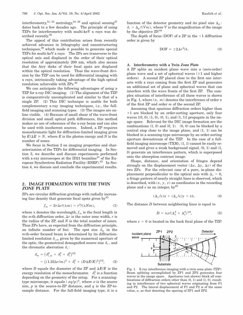
A. Interferometry with a Twin Zone PlateA ZP splits an incident plane wave into a (zero-order)plane wave and a set of spherical waves (61 and higherorders). A second ZP placed close to the first one inter-acts with x rays coming from the first ZP and generatesan additional set of plane and spherical waves that caninterfere with the wave fronts of the first ZP. The com-plex situation of interference of all these waves is shownin Fig. 1, where (n, m) denotes the interference of order nof the first ZP and order m of the second ZP.
Assuming that spurious diffraction orders higher than11 are blocked by an order-sorting aperture, only fourwaves [(0, 0), (1, 0), (0, 1), and (1, 1)] propagate in the im-age space. Relevant for the DIC image formation are thecombinations (1, 0) and (0, 1). (0, 0) can be blocked by acentral stop close to the image plane, and (1, 1) can beblocked in a scanning-type microscope by an order-sortingaperture downstream of the TZP. In the case of a full-field imaging microscope (TXM), (1, 1) cannot be easily re-moved and gives a weak background signal. (0, 1) and (1,0) generate an interference pattern, which is superposedonto the absorption contrast image.
Shape, distance, and orientation of fringes dependstrongly on the displacement vector (Dx, Dy, Dz) of thetwo ZPs. For the relevant case of a pure, in-plane dis-placement perpendicular to the optical axis with Dz 5 0,a fringe pattern of nearly straight lines is observed, whichis described, with (x, y, z) as coordinates in the recordingplane and s as an integer, by45
~Dx /z !x 1 ~Dy /z !y 5 sl. (4)
The distance D between neighboring lines is equal to
D 5 lz/~Dx2 1 Dy
2!1/2, (5)
where z 5 0 is located in the back focal plane of the TZP.
Fig. 1. X-ray interference imaging with a twin zone plate (TZP).Beam splitting accomplished by ZP1 and ZP2 generates fourwaves in the image space. Apertures (not shown) block all com-binations of diffraction orders other than (0, 1) and (1, 0), result-ing in interference of two spherical waves originating from P1and P2. The lateral displacement of P1 and P2 is of the samevalue, a, as that denoting the spacing of ZP1 and ZP2.
Kaulich et al. Vol. 19, No. 4 /April 2002 /J. Opt. Soc. Am. A 799
Thus an interference pattern generated by a TZP al-lows for complete control of fringe orientation and spacingif it is possible to control the distance vector between bothZPs with sufficient accuracy.
B. Differential Interference Imaging with a Twin ZonePlateDifferential imaging means that the lateral image sepa-ration is smaller than the optical resolution of the imag-ing optics or, in terms of a scanning probe geometry, thatthe distance of the maxima of the Airy disks of both ZPs issmaller than their optical resolution.
With use of the full-field imaging geometry as describedbelow, the image field �I is given by �I 5 �pz/f, wherethe diameter of the order-sorting aperture is �p . As-suming for simplicity that the ZPs are displaced only inthe x direction, the condition for the necessary displace-ment can be described as
Dx , 2rDr/�p . (6)
ZP imaging fulfills this condition when the lateral dis-placement of the two ZPs is of the order of the outermostzone width Dr.
In addition, the separation Dz of the ZPs along the op-tical axis has to be well within the DOF. Otherwise, twodifferently sized images would be observed. According toEq. (3), this leads to the condition
Dz , 4Dr2/l. (7)
C. Coherence ConsiderationsTo understand why DIC imaging with ZPs in the de-scribed geometry setup works, one has to consider the re-quirements that this method places on both spatial andtemporal coherence of the light source.
1. Spatial CoherenceThe van Cittert–Zernike theorem applied to the case of acircular light source of diameter d located a distance Lfrom a plane of observation gives a limit for the coher-ently illuminated field D (Ref. 46):
D 5 0.61Ll
d/2. (8)
On the other hand, the spatial resolution of a ZP is, ac-cording to the Rayleigh criterion, determined by d5 1.22Dr [from Eq. (2), considering an ideal point sourceand negligible monochromatic aberration].
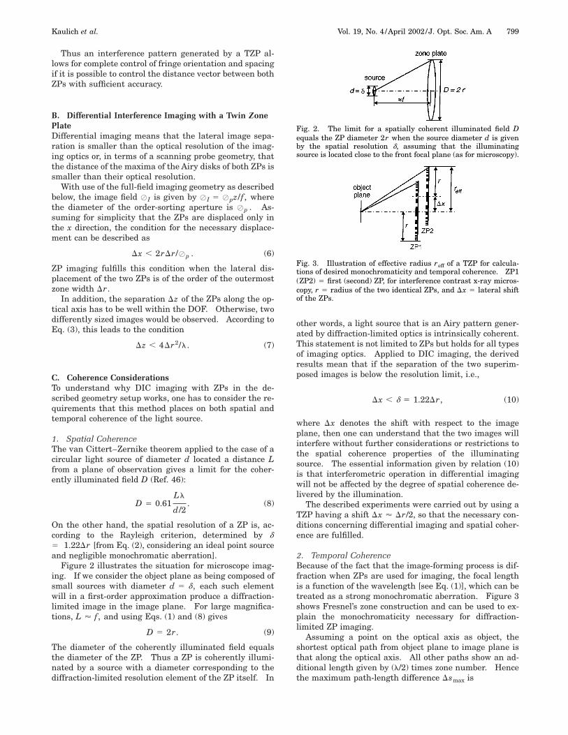
Figure 2 illustrates the situation for microscope imag-ing. If we consider the object plane as being composed ofsmall sources with diameter d 5 d, each such elementwill in a first-order approximation produce a diffraction-limited image in the image plane. For large magnifica-tions, L ' f, and using Eqs. (1) and (8) gives
D 5 2r. (9)
The diameter of the coherently illuminated field equalsthe diameter of the ZP. Thus a ZP is coherently illumi-nated by a source with a diameter corresponding to thediffraction-limited resolution element of the ZP itself. In
other words, a light source that is an Airy pattern gener-ated by diffraction-limited optics is intrinsically coherent.This statement is not limited to ZPs but holds for all typesof imaging optics. Applied to DIC imaging, the derivedresults mean that if the separation of the two superim-posed images is below the resolution limit, i.e.,
Dx , d 5 1.22Dr, (10)
where Dx denotes the shift with respect to the imageplane, then one can understand that the two images willinterfere without further considerations or restrictions tothe spatial coherence properties of the illuminatingsource. The essential information given by relation (10)is that interferometric operation in differential imagingwill not be affected by the degree of spatial coherence de-livered by the illumination.
The described experiments were carried out by using aTZP having a shift Dx ' Dr/2, so that the necessary con-ditions concerning differential imaging and spatial coher-ence are fulfilled.
2. Temporal CoherenceBecause of the fact that the image-forming process is dif-fraction when ZPs are used for imaging, the focal lengthis a function of the wavelength [see Eq. (1)], which can betreated as a strong monochromatic aberration. Figure 3shows Fresnel’s zone construction and can be used to ex-plain the monochromaticity necessary for diffraction-limited ZP imaging.
Assuming a point on the optical axis as object, theshortest optical path from object plane to image plane isthat along the optical axis. All other paths show an ad-ditional length given by (l/2) times zone number. Hencethe maximum path-length difference Dsmax is
Fig. 2. The limit for a spatially coherent illuminated field Dequals the ZP diameter 2r when the source diameter d is givenby the spatial resolution d, assuming that the illuminatingsource is located close to the front focal plane (as for microscopy).
Fig. 3. Illustration of effective radius reff of a TZP for calcula-tions of desired monochromaticity and temporal coherence. ZP1(ZP2) 5 first (second) ZP, for interference contrast x-ray micros-copy, r 5 radius of the two identical ZPs, and Dx 5 lateral shiftof the ZPs.
800 J. Opt. Soc. Am. A/Vol. 19, No. 4 /April 2002 Kaulich et al.
Dsmax 5l
2N, (11)
where N denotes the total number of zones. The addi-tional optical path-length differences introduced by thespecimen’s structure is negligible in terms of coherenceconsiderations for almost all objects in x-ray microscopy:Assuming a typical object thickness ('10 mm) and varia-tion of the real part of the refractive index ('1024) leadsto optical path-length differences in the nanometer range,corresponding to a few wavelengths, which is small com-pared with the number resulting from the monochroma-ticity desired for ZP imaging. For the observation of con-structive interference of light coming from all zones in theimage plane, the condition for the coherence length lcoh ofthe illuminating light is
lcoh > Dsmax . (12)
If we consider the general formula lcoh 5 l2/(2Dl) for thecoherence length, where Dl denotes the FWHM of thespectral distribution, Eq. (11) for the maximum path-length difference results in
lcoh 5l2
2Dl>
l
2N 5 Dsmax , (13)
which finally gives
l
Dl> N (14)
(cf. Ref. 38). For example, the monochromaticity thathas to be achieved by an appropriate monochromatorshould at least be as high as the number of zones. Forinterference imaging with two ZPs, the lateral displace-ment of the ZPs leads to further constraints. In theabove given model, calculations for time-coherent illumi-nation of two ZPs shifted with respect to each other haveto take into consideration all parts of both ZPs. In thecase of two ZPs with equal radius r and small distancealong the optical axis, an effective radius reff may be in-troduced. From Fig. 3, it can be derived that here reff is
reff 5 r 1 Dx. (15)
The number of zones N and the radius r of a ZP are re-lated by44
N 5r2
lf. (16)
In a first-order approximation, this gives
Neff 5reff
2
lf5
~r 1 Dx !2
lf(17)
for the effective zone number Neff and
DN 5 Neff 2 N 5~2r 1 Dx !Dx
lf(18)
for the number of additional zones. In practical cases,one can assume that r @ Dx, so that
DN '2rDx
lf. (19)
For differential imaging, Dx < Dr, and Eq. (1) and rela-tion (19) give for a maximum value Dx 5 Dr the relation
DN ' 1, (20)
which is obvious from a geometrical point of view if onetreats the two ZPs as being located in the same plane per-pendicular to the optical axis. The effective zone numberNeff , which determines the requirements of DIC imagingto the temporal coherence and thus the monochromaticityof the illumination, is
Neff 5 N 1 DN 5 N 1 1 ' N. (21)
The approximation N 1 1 ' N assumes large zone num-bers, which is valid for typical ZPs implemented in x-raymicroscopy, where N exceeds 100.
From the above given calculations, it can be stated thatthe requirements concerning temporal coherence neededfor DIC with TZPs are satisfied when the monochromatic-ity of the illumination is sufficient for diffraction-limitedimaging, that is, l/Dl > N. Thus no precautions withrespect to the spectrum of the illuminating source otherthan those for ‘‘normal’’ ZP imaging have to be considered.
D. Generation and Image Performance of the TwinZone PlateFollowing the above considerations, we fabricated TZPsin Au with the following geometrical characteristics at aphoton energy of 4 keV: 37.75 mm in radius, first-orderfocal length of 50 mm, outermost zone width of 200 nm,and zone height of 420 nm. The ZPs were built byelectron-beam lithography and electroplating on bothsides of a 1-mm-thick Si3N4 window. The nominal dis-placement of the two ZPs was less than 100 nm.
The theoretical first-order diffraction efficiency (that is,the fraction of the incoming light diffracted in the first or-der) of each ZP is 14%; the zero-order contribution is cal-culated to be 35%.
For the calculation of the total diffraction efficiency ofthe TZP, the zero-order transmissions of the two ZPs alsohave to be taken into account (zero order passing throughthe first ZP and diffracted in first order by the second ZPplus first order of the first ZP; that is, weakened by thezero-order transmission of the second ZP). The total dif-fraction efficiency htot can be expressed as
htot 5 tZP1hZP2 1 tZP2hZP1 , (22)
where the transmission of the first (second) ZP is tZP1(tZP2) and the diffraction efficiency of the first (second) ZPis hZP1 (hZP2).
This consideration is based on the fact that the diffrac-tion of both ZPs can be treated as independent. Themeasured first-order diffraction efficiency of the TZP is9.6% at 4 keV, which is close to the theoretically expectedvalue. The efficiency value was acquired by measuringthe first-order flux through an aperture in the back focalplane of the TZP and normalizing it with the flux throughan aperture with the same diameter as that of the TZP.
The optical resolution was measured by imaging a WSiemens star with a full-field imaging microscope (TXM)
Kaulich et al. Vol. 19, No. 4 /April 2002 /J. Opt. Soc. Am. A 801
(see Subsection 3.A). The Siemens star is 20 mm in di-ameter and 300 nm in thickness and has 36 spokes withline widths varying from 2 mm down to 0.1 mm. From thex-ray image shown in Fig. 4, periods of approximately 320nm could be resolved.
3. DIFFERENTIAL INTERFERENCEMICROSCOPY WITH MULTI-keV PHOTONSThe experiments were performed at the ID21 x-ray mi-croscopy beamline41 at the ESRF. The x-ray beam at thisbeamline is generated by a 1.6-m-long, 42-mm-period un-dulator, which is here used at a photon energy of 4 keV.With an undulator K value of 1.45, the measuredintegrated flux is 7 3 1011 photons s21 (Si^111&BW)21
(200 mA)21 at a beam size of 0.5 mm 3 0.5 mm. Thex-ray source size (FWHM) at this photon energy is 140mm horizontally and 24 mm vertically.
The beam is preconditioned by two bounce reflectionsfrom two parallel, horizontally deflecting Ni-coated mir-rors. At a glancing angle of 8 mrad, the Ni reflectionsgive a cutoff energy of 10 keV. This gives a total har-monic suppression for 12-keV photons (third harmonic) ofbetter than 103 and greatly reduces the incident power onthe downstream optical components. Contributions ofthe second harmonic at 8 keV are suppressed by a Si^111&crystal monochromator. The bremsstrahlung and scat-tered radiation is separated from the offset undulator ra-diation by passage through a narrow hole in a tungstenblock in combination with a collimator. This allows for atremendous reduction of downstream radiation shieldingand offers relatively free access to the microscope duringexperiments.
The ID21 beamline houses two x-ray microscopes ontwo independent branch lines: a scanning x-ray micro-scope (SXM) on the direct branch and a full-field imaging
Fig. 4. X-ray image of a W Siemens star taken with the full-fieldimaging microscope (TXM) in differential interference contrast(DIC) mode. The Siemens star with 20-mm diameter and 36spokes with line widths varying from 2 to 0.1 mm served as a testspecimen to measure the optical resolution. Periods of 320 nmcould be resolved.
microscope (TXM) on a side branch. Both microscopeswere used for proving the feasibility of DIC with TZPs at4-keV photon energy.
A. Differential Interference Contrast X-Ray Imagingwith a Full-Field Imaging MicroscopeThe full-field imaging microscope, or TXM, works simi-larly to a visible-light transmission microscope, despitethe fact that ZPs are used as focusing optics: The x-raybeam is monochromatized by a Si crystal monochromatorwith an energy resolution of 0.7 eV at a photon energy of4 keV.47 A condenser ZP focuses the x-ray beam onto thesample. A high-optical-resolution ZP downstream of thesample then generates a magnified image onto a CCDcamera. When the TXM is operated in DIC mode (seeFig. 5a), the TZP is placed as the imaging objective behindthe sample and (0, 1) and (1, 0) wave fronts generate theimage within the (0, 0) contribution of the condenser illu-
Fig. 5. a, Optical scheme of the TXM used for the x-ray DIC im-aging at the ID21 x-ray microscopy beamline of the EuropeanSynchrotron Radiation Facility. The x-ray beam from the sourceis monochromatized by a Si crystal monochromator (not includedin the sketch) and focused by a condenser optic onto the sample.The TZP upstream of the sample generates a magnified image,which is detected by a CCD camera. b, Because of the small nu-merical aperture of the condenser illumination, the 11-order im-age is overlapped with the 21-order projection. Therefore a pin-hole is aligned slightly off axis close to the sample in order toseparate the 11 and 21 order. CS stands for central stop, andCZP refers to the condenser ZP.
802 J. Opt. Soc. Am. A/Vol. 19, No. 4 /April 2002 Kaulich et al.
mination. Operation of the TXM with partially coherentor incoherent illumination in DIC mode is possible, as ex-plained in Section 2.
The condenser ZP currently in use has a diameter of 1.2mm, an outermost zone width DrN 5 826 nm, and a focallength of 3630 mm. The measured photon flux in the fo-cal spot at 4 keV is 3 3 108 photons s21 (Si^111&BW)(200 mA)21. Because of the mismatch of the numericalapertures of condenser and imaging objective and thesmall numerical aperture of the condenser, the 11-orderimage would be overlapped with the 21-order projectionwith slightly different magnification. Therefore an off-axis geometry was applied by introducing a 50-mm-diameter aperture off axis close to the sample, as shownin Fig. 5b, in order to separate the (11, 0) and (0, 11)wave fronts from the (0, 0), (21, 0), and (0, 21) wavefronts.48 This introduces a weak, oblique illuminationand limits the usable image field. (0, 0) contributions areblocked by a central stop close to the CCD, which was aPrinceton CCD (EEV chip with 1340 3 1240 pixels and apixel size of 20 mm 3 20 mm) coupled by a two-stagevisible-light optical system to a Gd2O2S:Tb powder phos-phor screen with a thickness of 10 mm.49,50
As a good test object for phase-sensitive imaging at 4keV, poly(methylmethacrylate) (PMMA) structures with athickness t 5 2 mm are used. The phase-shifting, realpart of these structures is, at a photon energy of 4 keV, 2orders of magnitude higher (d 5 1.68 3 1025) than theabsorbing, imaginary part (b 5 1.57 3 1027) of the re-fractive index n 5 1 2 d 2 ib. Taking into account thatthe transmission of PMMA is here 98.8%, one can expectan increase in contrast when the x-ray DIC technique isapplied. The corresponding phase shift f 5 (2p/l)dt is0.706 rad at 4-keV photon energy.
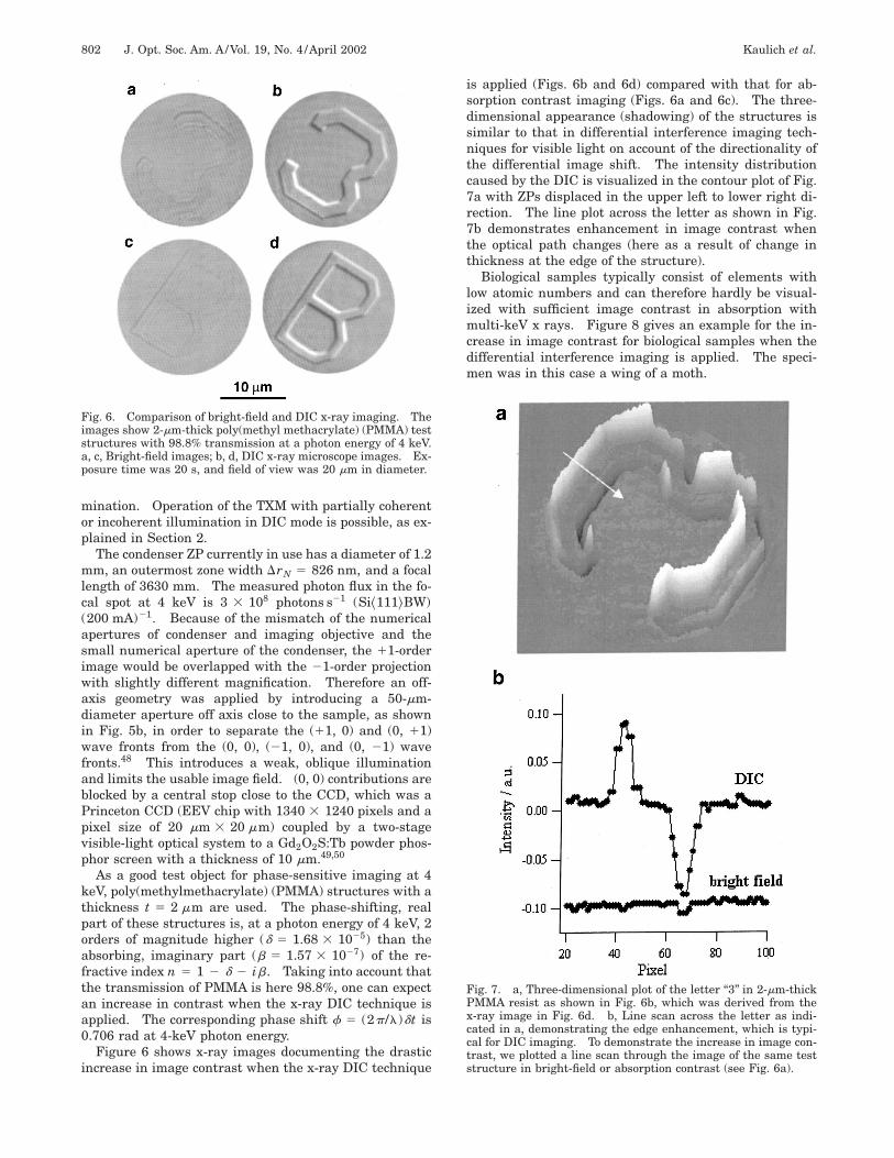
Figure 6 shows x-ray images documenting the drasticincrease in image contrast when the x-ray DIC technique
Fig. 6. Comparison of bright-field and DIC x-ray imaging. Theimages show 2-mm-thick poly(methyl methacrylate) (PMMA) teststructures with 98.8% transmission at a photon energy of 4 keV.a, c, Bright-field images; b, d, DIC x-ray microscope images. Ex-posure time was 20 s, and field of view was 20 mm in diameter.
is applied (Figs. 6b and 6d) compared with that for ab-sorption contrast imaging (Figs. 6a and 6c). The three-dimensional appearance (shadowing) of the structures issimilar to that in differential interference imaging tech-niques for visible light on account of the directionality ofthe differential image shift. The intensity distributioncaused by the DIC is visualized in the contour plot of Fig.7a with ZPs displaced in the upper left to lower right di-rection. The line plot across the letter as shown in Fig.7b demonstrates enhancement in image contrast whenthe optical path changes (here as a result of change inthickness at the edge of the structure).
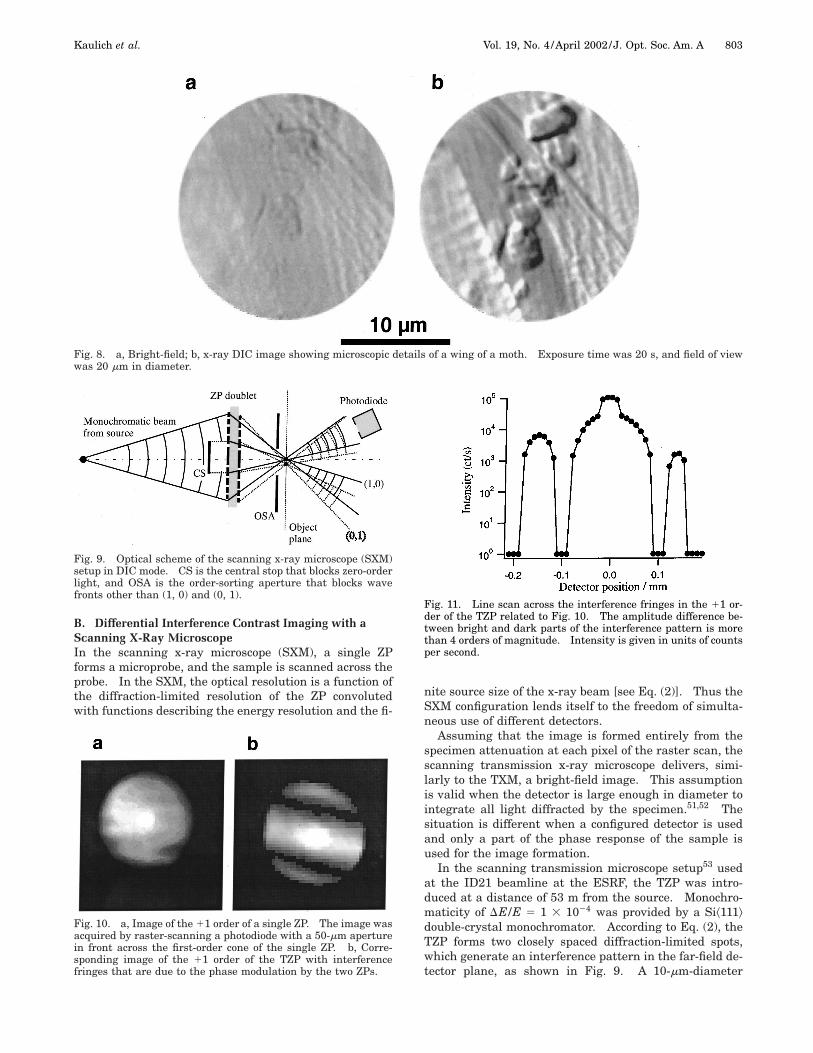
Biological samples typically consist of elements withlow atomic numbers and can therefore hardly be visual-ized with sufficient image contrast in absorption withmulti-keV x rays. Figure 8 gives an example for the in-crease in image contrast for biological samples when thedifferential interference imaging is applied. The speci-men was in this case a wing of a moth.
Fig. 7. a, Three-dimensional plot of the letter ‘‘3’’ in 2-mm-thickPMMA resist as shown in Fig. 6b, which was derived from thex-ray image in Fig. 6d. b, Line scan across the letter as indi-cated in a, demonstrating the edge enhancement, which is typi-cal for DIC imaging. To demonstrate the increase in image con-trast, we plotted a line scan through the image of the same teststructure in bright-field or absorption contrast (see Fig. 6a).
Kaulich et al. Vol. 19, No. 4 /April 2002 /J. Opt. Soc. Am. A 803
Fig. 8. a, Bright-field; b, x-ray DIC image showing microscopic details of a wing of a moth. Exposure time was 20 s, and field of viewwas 20 mm in diameter.
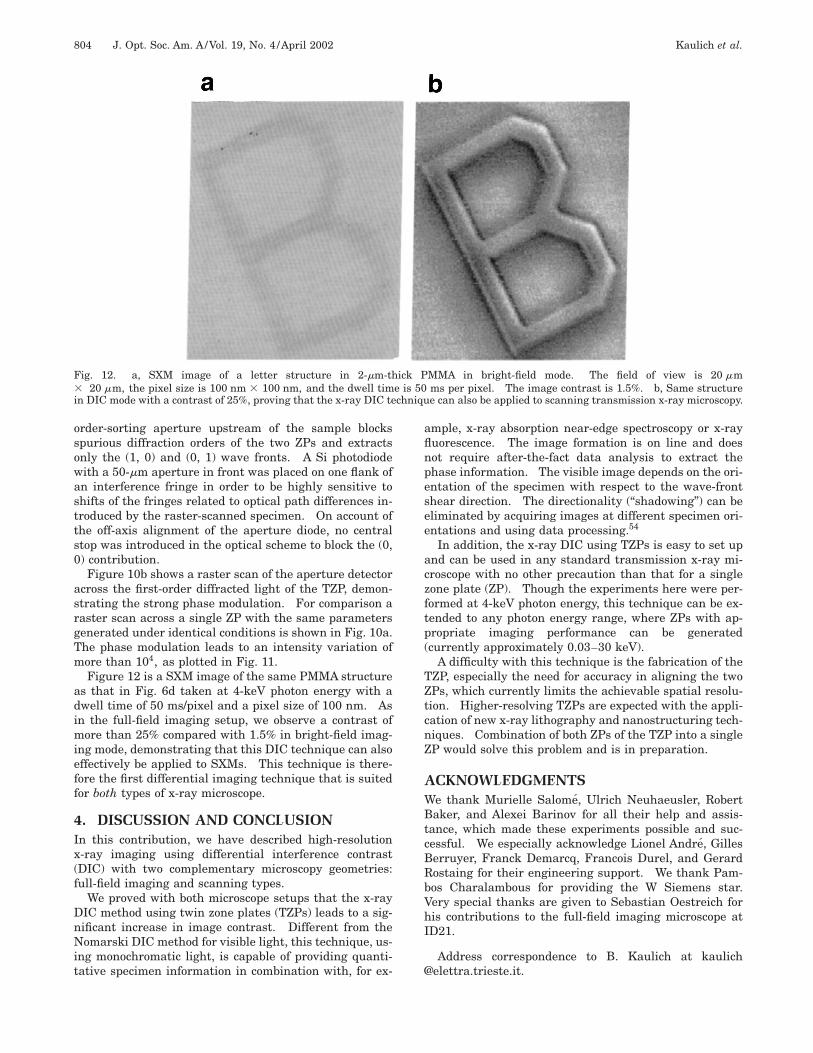
B. Differential Interference Contrast Imaging with aScanning X-Ray MicroscopeIn the scanning x-ray microscope (SXM), a single ZPforms a microprobe, and the sample is scanned across theprobe. In the SXM, the optical resolution is a function ofthe diffraction-limited resolution of the ZP convolutedwith functions describing the energy resolution and the fi-
Fig. 9. Optical scheme of the scanning x-ray microscope (SXM)setup in DIC mode. CS is the central stop that blocks zero-orderlight, and OSA is the order-sorting aperture that blocks wavefronts other than (1, 0) and (0, 1).
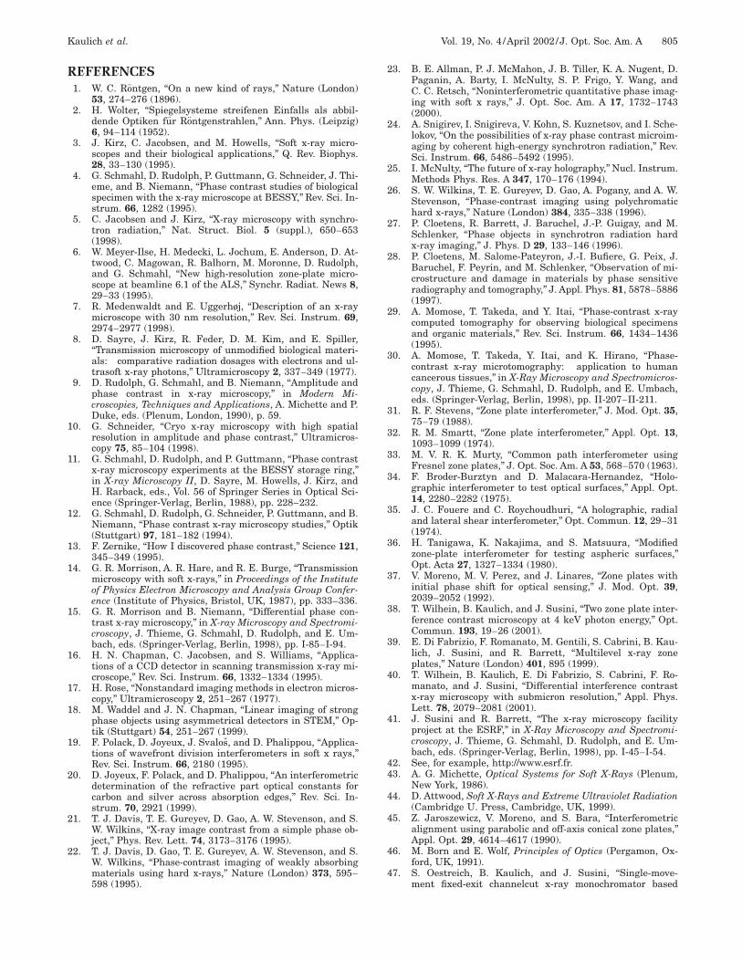
Fig. 10. a, Image of the 11 order of a single ZP. The image wasacquired by raster-scanning a photodiode with a 50-mm aperturein front across the first-order cone of the single ZP. b, Corre-sponding image of the 11 order of the TZP with interferencefringes that are due to the phase modulation by the two ZPs.
nite source size of the x-ray beam [see Eq. (2)]. Thus theSXM configuration lends itself to the freedom of simulta-neous use of different detectors.
Assuming that the image is formed entirely from thespecimen attenuation at each pixel of the raster scan, thescanning transmission x-ray microscope delivers, simi-larly to the TXM, a bright-field image. This assumptionis valid when the detector is large enough in diameter tointegrate all light diffracted by the specimen.51,52 Thesituation is different when a configured detector is usedand only a part of the phase response of the sample isused for the image formation.
In the scanning transmission microscope setup53 usedat the ID21 beamline at the ESRF, the TZP was intro-duced at a distance of 53 m from the source. Monochro-maticity of DE/E 5 1 3 1024 was provided by a Si^111&double-crystal monochromator. According to Eq. (2), theTZP forms two closely spaced diffraction-limited spots,which generate an interference pattern in the far-field de-tector plane, as shown in Fig. 9. A 10-mm-diameter
Fig. 11. Line scan across the interference fringes in the 11 or-der of the TZP related to Fig. 10. The amplitude difference be-tween bright and dark parts of the interference pattern is morethan 4 orders of magnitude. Intensity is given in units of countsper second.
804 J. Opt. Soc. Am. A/Vol. 19, No. 4 /April 2002 Kaulich et al.
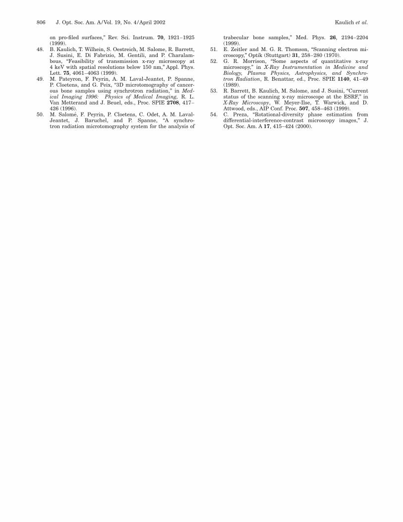
Fig. 12. a, SXM image of a letter structure in 2-mm-thick PMMA in bright-field mode. The field of view is 20 mm3 20 mm, the pixel size is 100 nm 3 100 nm, and the dwell time is 50 ms per pixel. The image contrast is 1.5%. b, Same structurein DIC mode with a contrast of 25%, proving that the x-ray DIC technique can also be applied to scanning transmission x-ray microscopy.
order-sorting aperture upstream of the sample blocksspurious diffraction orders of the two ZPs and extractsonly the (1, 0) and (0, 1) wave fronts. A Si photodiodewith a 50-mm aperture in front was placed on one flank ofan interference fringe in order to be highly sensitive toshifts of the fringes related to optical path differences in-troduced by the raster-scanned specimen. On account ofthe off-axis alignment of the aperture diode, no centralstop was introduced in the optical scheme to block the (0,0) contribution.
Figure 10b shows a raster scan of the aperture detectoracross the first-order diffracted light of the TZP, demon-strating the strong phase modulation. For comparison araster scan across a single ZP with the same parametersgenerated under identical conditions is shown in Fig. 10a.The phase modulation leads to an intensity variation ofmore than 104, as plotted in Fig. 11.
Figure 12 is a SXM image of the same PMMA structureas that in Fig. 6d taken at 4-keV photon energy with adwell time of 50 ms/pixel and a pixel size of 100 nm. Asin the full-field imaging setup, we observe a contrast ofmore than 25% compared with 1.5% in bright-field imag-ing mode, demonstrating that this DIC technique can alsoeffectively be applied to SXMs. This technique is there-fore the first differential imaging technique that is suitedfor both types of x-ray microscope.
4. DISCUSSION AND CONCLUSIONIn this contribution, we have described high-resolutionx-ray imaging using differential interference contrast(DIC) with two complementary microscopy geometries:full-field imaging and scanning types.
We proved with both microscope setups that the x-rayDIC method using twin zone plates (TZPs) leads to a sig-nificant increase in image contrast. Different from theNomarski DIC method for visible light, this technique, us-ing monochromatic light, is capable of providing quanti-tative specimen information in combination with, for ex-
ample, x-ray absorption near-edge spectroscopy or x-rayfluorescence. The image formation is on line and doesnot require after-the-fact data analysis to extract thephase information. The visible image depends on the ori-entation of the specimen with respect to the wave-frontshear direction. The directionality (‘‘shadowing’’) can beeliminated by acquiring images at different specimen ori-entations and using data processing.54
In addition, the x-ray DIC using TZPs is easy to set upand can be used in any standard transmission x-ray mi-croscope with no other precaution than that for a singlezone plate (ZP). Though the experiments here were per-formed at 4-keV photon energy, this technique can be ex-tended to any photon energy range, where ZPs with ap-propriate imaging performance can be generated(currently approximately 0.03–30 keV).
A difficulty with this technique is the fabrication of theTZP, especially the need for accuracy in aligning the twoZPs, which currently limits the achievable spatial resolu-tion. Higher-resolving TZPs are expected with the appli-cation of new x-ray lithography and nanostructuring tech-niques. Combination of both ZPs of the TZP into a singleZP would solve this problem and is in preparation.
ACKNOWLEDGMENTSWe thank Murielle Salome, Ulrich Neuhaeusler, RobertBaker, and Alexei Barinov for all their help and assis-tance, which made these experiments possible and suc-cessful. We especially acknowledge Lionel Andre, GillesBerruyer, Franck Demarcq, Francois Durel, and GerardRostaing for their engineering support. We thank Pam-bos Charalambous for providing the W Siemens star.Very special thanks are given to Sebastian Oestreich forhis contributions to the full-field imaging microscope atID21.
Kaulich et al. Vol. 19, No. 4 /April 2002 /J. Opt. Soc. Am. A 805
REFERENCES1. W. C. Rontgen, ‘‘On a new kind of rays,’’ Nature (London)
53, 274–276 (1896).2. H. Wolter, ‘‘Spiegelsysteme streifenen Einfalls als abbil-
dende Optiken fur Rontgenstrahlen,’’ Ann. Phys. (Leipzig)6, 94–114 (1952).
3. J. Kirz, C. Jacobsen, and M. Howells, ‘‘Soft x-ray micro-scopes and their biological applications,’’ Q. Rev. Biophys.28, 33–130 (1995).
4. G. Schmahl, D. Rudolph, P. Guttmann, G. Schneider, J. Thi-eme, and B. Niemann, ‘‘Phase contrast studies of biologicalspecimen with the x-ray microscope at BESSY,’’ Rev. Sci. In-strum. 66, 1282 (1995).
5. C. Jacobsen and J. Kirz, ‘‘X-ray microscopy with synchro-tron radiation,’’ Nat. Struct. Biol. 5 (suppl.), 650–653(1998).
6. W. Meyer-Ilse, H. Medecki, L. Jochum, E. Anderson, D. At-twood, C. Magowan, R. Balhorn, M. Moronne, D. Rudolph,and G. Schmahl, ‘‘New high-resolution zone-plate micro-scope at beamline 6.1 of the ALS,’’ Synchr. Radiat. News 8,29–33 (1995).
7. R. Medenwaldt and E. Uggerhøj, ‘‘Description of an x-raymicroscope with 30 nm resolution,’’ Rev. Sci. Instrum. 69,2974–2977 (1998).
8. D. Sayre, J. Kirz, R. Feder, D. M. Kim, and E. Spiller,‘‘Transmission microscopy of unmodified biological materi-als: comparative radiation dosages with electrons and ul-trasoft x-ray photons,’’ Ultramicroscopy 2, 337–349 (1977).
9. D. Rudolph, G. Schmahl, and B. Niemann, ‘‘Amplitude andphase contrast in x-ray microscopy,’’ in Modern Mi-croscopies, Techniques and Applications, A. Michette and P.Duke, eds. (Plenum, London, 1990), p. 59.
10. G. Schneider, ‘‘Cryo x-ray microscopy with high spatialresolution in amplitude and phase contrast,’’ Ultramicros-copy 75, 85–104 (1998).
11. G. Schmahl, D. Rudolph, and P. Guttmann, ‘‘Phase contrastx-ray microscopy experiments at the BESSY storage ring,’’in X-ray Microscopy II, D. Sayre, M. Howells, J. Kirz, andH. Rarback, eds., Vol. 56 of Springer Series in Optical Sci-ence (Springer-Verlag, Berlin, 1988), pp. 228–232.
12. G. Schmahl, D. Rudolph, G. Schneider, P. Guttmann, and B.Niemann, ‘‘Phase contrast x-ray microscopy studies,’’ Optik(Stuttgart) 97, 181–182 (1994).
13. F. Zernike, ‘‘How I discovered phase contrast,’’ Science 121,345–349 (1995).
14. G. R. Morrison, A. R. Hare, and R. E. Burge, ‘‘Transmissionmicroscopy with soft x-rays,’’ in Proceedings of the Instituteof Physics Electron Microscopy and Analysis Group Confer-ence (Institute of Physics, Bristol, UK, 1987), pp. 333–336.
15. G. R. Morrison and B. Niemann, ‘‘Differential phase con-trast x-ray microscopy,’’ in X-ray Microscopy and Spectromi-croscopy, J. Thieme, G. Schmahl, D. Rudolph, and E. Um-bach, eds. (Springer-Verlag, Berlin, 1998), pp. I-85–I-94.
16. H. N. Chapman, C. Jacobsen, and S. Williams, ‘‘Applica-tions of a CCD detector in scanning transmission x-ray mi-croscope,’’ Rev. Sci. Instrum. 66, 1332–1334 (1995).
17. H. Rose, ‘‘Nonstandard imaging methods in electron micros-copy,’’ Ultramicroscopy 2, 251–267 (1977).
18. M. Waddel and J. N. Chapman, ‘‘Linear imaging of strongphase objects using asymmetrical detectors in STEM,’’ Op-tik (Stuttgart) 54, 251–267 (1999).
19. F. Polack, D. Joyeux, J. Svalos, and D. Phalippou, ‘‘Applica-tions of wavefront division interferometers in soft x rays,’’Rev. Sci. Instrum. 66, 2180 (1995).
20. D. Joyeux, F. Polack, and D. Phalippou, ‘‘An interferometricdetermination of the refractive part optical constants forcarbon and silver across absorption edges,’’ Rev. Sci. In-strum. 70, 2921 (1999).
21. T. J. Davis, T. E. Gureyev, D. Gao, A. W. Stevenson, and S.W. Wilkins, ‘‘X-ray image contrast from a simple phase ob-ject,’’ Phys. Rev. Lett. 74, 3173–3176 (1995).
22. T. J. Davis, D. Gao, T. E. Gureyev, A. W. Stevenson, and S.W. Wilkins, ‘‘Phase-contrast imaging of weakly absorbingmaterials using hard x-rays,’’ Nature (London) 373, 595–598 (1995).
23. B. E. Allman, P. J. McMahon, J. B. Tiller, K. A. Nugent, D.Paganin, A. Barty, I. McNulty, S. P. Frigo, Y. Wang, andC. C. Retsch, ‘‘Noninterferometric quantitative phase imag-ing with soft x rays,’’ J. Opt. Soc. Am. A 17, 1732–1743(2000).
24. A. Snigirev, I. Snigireva, V. Kohn, S. Kuznetsov, and I. Sche-lokov, ‘‘On the possibilities of x-ray phase contrast microim-aging by coherent high-energy synchrotron radiation,’’ Rev.Sci. Instrum. 66, 5486–5492 (1995).
25. I. McNulty, ‘‘The future of x-ray holography,’’ Nucl. Instrum.Methods Phys. Res. A 347, 170–176 (1994).
26. S. W. Wilkins, T. E. Gureyev, D. Gao, A. Pogany, and A. W.Stevenson, ‘‘Phase-contrast imaging using polychromatichard x-rays,’’ Nature (London) 384, 335–338 (1996).
27. P. Cloetens, R. Barrett, J. Baruchel, J.-P. Guigay, and M.Schlenker, ‘‘Phase objects in synchrotron radiation hardx-ray imaging,’’ J. Phys. D 29, 133–146 (1996).
28. P. Cloetens, M. Salome-Pateyron, J.-I. Bufiere, G. Peix, J.Baruchel, F. Peyrin, and M. Schlenker, ‘‘Observation of mi-crostructure and damage in materials by phase sensitiveradiography and tomography,’’ J. Appl. Phys. 81, 5878–5886(1997).
29. A. Momose, T. Takeda, and Y. Itai, ‘‘Phase-contrast x-raycomputed tomography for observing biological specimensand organic materials,’’ Rev. Sci. Instrum. 66, 1434–1436(1995).
30. A. Momose, T. Takeda, Y. Itai, and K. Hirano, ‘‘Phase-contrast x-ray microtomography: application to humancancerous tissues,’’ in X-Ray Microscopy and Spectromicros-copy, J. Thieme, G. Schmahl, D. Rudolph, and E. Umbach,eds. (Springer-Verlag, Berlin, 1998), pp. II-207–II-211.
31. R. F. Stevens, ‘‘Zone plate interferometer,’’ J. Mod. Opt. 35,75–79 (1988).
32. R. M. Smartt, ‘‘Zone plate interferometer,’’ Appl. Opt. 13,1093–1099 (1974).
33. M. V. R. K. Murty, ‘‘Common path interferometer usingFresnel zone plates,’’ J. Opt. Soc. Am. A 53, 568–570 (1963).
34. F. Broder-Burztyn and D. Malacara-Hernandez, ‘‘Holo-graphic interferometer to test optical surfaces,’’ Appl. Opt.14, 2280–2282 (1975).
35. J. C. Fouere and C. Roychoudhuri, ‘‘A holographic, radialand lateral shear interferometer,’’ Opt. Commun. 12, 29–31(1974).
36. H. Tanigawa, K. Nakajima, and S. Matsuura, ‘‘Modifiedzone-plate interferometer for testing aspheric surfaces,’’Opt. Acta 27, 1327–1334 (1980).
37. V. Moreno, M. V. Perez, and J. Linares, ‘‘Zone plates withinitial phase shift for optical sensing,’’ J. Mod. Opt. 39,2039–2052 (1992).
38. T. Wilhein, B. Kaulich, and J. Susini, ‘‘Two zone plate inter-ference contrast microscopy at 4 keV photon energy,’’ Opt.Commun. 193, 19–26 (2001).
39. E. Di Fabrizio, F. Romanato, M. Gentili, S. Cabrini, B. Kau-lich, J. Susini, and R. Barrett, ‘‘Multilevel x-ray zoneplates,’’ Nature (London) 401, 895 (1999).
40. T. Wilhein, B. Kaulich, E. Di Fabrizio, S. Cabrini, F. Ro-manato, and J. Susini, ‘‘Differential interference contrastx-ray microscopy with submicron resolution,’’ Appl. Phys.Lett. 78, 2079–2081 (2001).
41. J. Susini and R. Barrett, ‘‘The x-ray microscopy facilityproject at the ESRF,’’ in X-Ray Microscopy and Spectromi-croscopy, J. Thieme, G. Schmahl, D. Rudolph, and E. Um-bach, eds. (Springer-Verlag, Berlin, 1998), pp. I-45–I-54.
42. See, for example, http://www.esrf.fr.43. A. G. Michette, Optical Systems for Soft X-Rays (Plenum,
New York, 1986).44. D. Attwood, Soft X-Rays and Extreme Ultraviolet Radiation
(Cambridge U. Press, Cambridge, UK, 1999).45. Z. Jaroszewicz, V. Moreno, and S. Bara, ‘‘Interferometric
alignment using parabolic and off-axis conical zone plates,’’Appl. Opt. 29, 4614–4617 (1990).
46. M. Born and E. Wolf, Principles of Optics (Pergamon, Ox-ford, UK, 1991).
47. S. Oestreich, B. Kaulich, and J. Susini, ‘‘Single-move-ment fixed-exit channelcut x-ray monochromator based
806 J. Opt. Soc. Am. A/Vol. 19, No. 4 /April 2002 Kaulich et al.
on pro-filed surfaces,’’ Rev. Sci. Instrum. 70, 1921–1925(1999).
48. B. Kaulich, T. Wilhein, S. Oestreich, M. Salome, R. Barrett,J. Susini, E. Di Fabrizio, M. Gentili, and P. Charalam-bous, ‘‘Feasibility of transmission x-ray microscopy at4 keV with spatial resolutions below 150 nm,’’ Appl. Phys.Lett. 75, 4061–4063 (1999).
49. M. Pateyron, F. Peyrin, A. M. Laval-Jeantet, P. Spanne,P. Cloetens, and G. Peix, ‘‘3D microtomography of cancer-ous bone samples using synchrotron radiation,’’ in Med-ical Imaging 1996: Physics of Medical Imaging, R. L.Van Metterand and J. Beuel, eds., Proc. SPIE 2708, 417–426 (1996).
50. M. Salome, F. Peyrin, P. Cloetens, C. Odet, A. M. Laval-Jeantet, J. Baruchel, and P. Spanne, ‘‘A synchro-tron radiation microtomography system for the analysis of
trabecular bone samples,’’ Med. Phys. 26, 2194–2204(1999).
51. E. Zeitler and M. G. R. Thomson, ‘‘Scanning electron mi-croscopy,’’ Optik (Stuttgart) 31, 258–280 (1970).
52. G. R. Morrison, ‘‘Some aspects of quantitative x-raymicroscopy,’’ in X-Ray Instrumentation in Medicine andBiology, Plasma Physics, Astrophysics, and Synchro-tron Radiation, R. Benattar, ed., Proc. SPIE 1140, 41–49(1989).
53. R. Barrett, B. Kaulich, M. Salome, and J. Susini, ‘‘Currentstatus of the scanning x-ray microscope at the ESRF,’’ inX-Ray Microscopy, W. Meyer-Ilse, T. Warwick, and D.Attwood, eds., AIP Conf. Proc. 507, 458–463 (1999).
54. C. Preza, ‘‘Rotational-diversity phase estimation fromdifferential-interference-contrast microscopy images,’’ J.Opt. Soc. Am. A 17, 415–424 (2000).