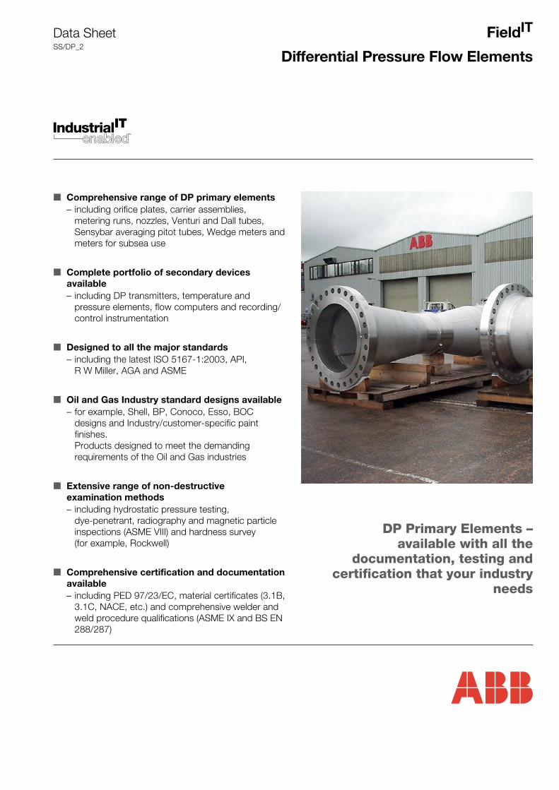
Field IT Differential Pressure Flow Elements ■ Comprehensive range of DP primary elements – including orifice plates, carrier assemblies, metering runs, nozzles, Venturi and Dall tubes, Sensybar averaging pitot tubes, Wedge meters and meters for subsea use ■ Complete portfolio of secondary devices available – including DP transmitters, temperature and pressure elements, flow computers and recording/ control instrumentation ■ Designed to all the major standards – including the latest ISO 5167-1:2003, API, R W Miller, AGA and ASME ■ Oil and Gas Industry standard designs available – for example, Shell, BP, Conoco, Esso, BOC designs and Industry/customer-specific paint finishes. Products designed to meet the demanding requirements of the Oil and Gas industries ■ Extensive range of non-destructive examination methods – including hydrostatic pressure testing, dye-penetrant, radiography and magnetic particle inspections (ASME VIII) and hardness survey (for example, Rockwell) ■ Comprehensive certification and documentation available – including PED 97/23/EC, material certificates (3.1B, 3.1C, NACE, etc.) and comprehensive welder and weld procedure qualifications (ASME IX and BS EN 288/287) Data Sheet SS/DP_2 DP Primary Elements – available with all the documentation, testing and certification that your industry needs
Transcript
FieldIT
Differential Pressure Flow Elements
■ Comprehensive range of DP primary elements– including orifice plates, carrier assemblies,
metering runs, nozzles, Venturi and Dall tubes,Sensybar averaging pitot tubes, Wedge meters andmeters for subsea use
■ Complete portfolio of secondary devicesavailable– including DP transmitters, temperature and
pressure elements, flow computers and recording/control instrumentation
■ Designed to all the major standards– including the latest ISO 5167-1:2003, API,
R W Miller, AGA and ASME
■ Oil and Gas Industry standard designs available– for example, Shell, BP, Conoco, Esso, BOC
designs and Industry/customer-specific paintfinishes.Products designed to meet the demandingrequirements of the Oil and Gas industries
■ Extensive range of non-destructiveexamination methods– including hydrostatic pressure testing,
dye-penetrant, radiography and magnetic particleinspections (ASME VIII) and hardness survey(for example, Rockwell)
■ Comprehensive certification and documentationavailable– including PED 97/23/EC, material certificates (3.1B,
3.1C, NACE, etc.) and comprehensive welder andweld procedure qualifications (ASME IX and BS EN288/287)
Data SheetSS/DP_2
DP Primary Elements –available with all the
documentation, testing andcertification that your industry
needs
Differential Pressure Flow ElementsSS/DP_2
2
Total CapabilityAlthough it is over 100 years since the first DP devices wereused, they still form the largest installed base of all flowmeasurement loops, especially in the Process and Chemical/Oil/Gas sectors.
ABB has been supplying DP devices from their very beginningsin the 19th century and have unrivalled experience in the field,incorporating the expertise of Kent, Taylor and Bush Beach.Kent engineers were involved in the design and manufacture ofsome of the first Venturi tubes to be used in the UK and theunique Dall Tube was actually developed by one of Kent’shydraulic engineers, Horace E. Dall.
ABB can offer a complete range of DP Flowmeters – not only theprimary elements but also the secondary transmitter and therecording/control/indication instrumentation that you need.
The ABB range of DP Primary Elements includes the followingdevices:
Venturi Tubes
Dall Tubes
Dall Short Inserts
Wedge Meters
Averaging Pitot Tubes (Sensybars)
Orifice PlatesSquare-edged, Conical-entry and Quarter CircleConcentric, Eccentric and Segmental
Orifice Carrier Ring AssembliesIntegral and Split-Ring
Orifice Flange Assemblies
Meter RunsStandard and Integral
Flow NozzlesISA, Long Radius and ASME Throat-tap
Basic Principle of OperationDP devices work on a principle based upon the Law ofConservation of Energy, where a restriction in the fluid pathcauses an acceleration in the fluid velocity and hence anincrease in kinetic energy. The gain in kinetic energy is at theexpense of pressure energy and this is manifested as a drop influid pressure across the narrowest part of the restriction.
The drop in pressure and the flow rate are linked by the following(albeit simplified) relationship:
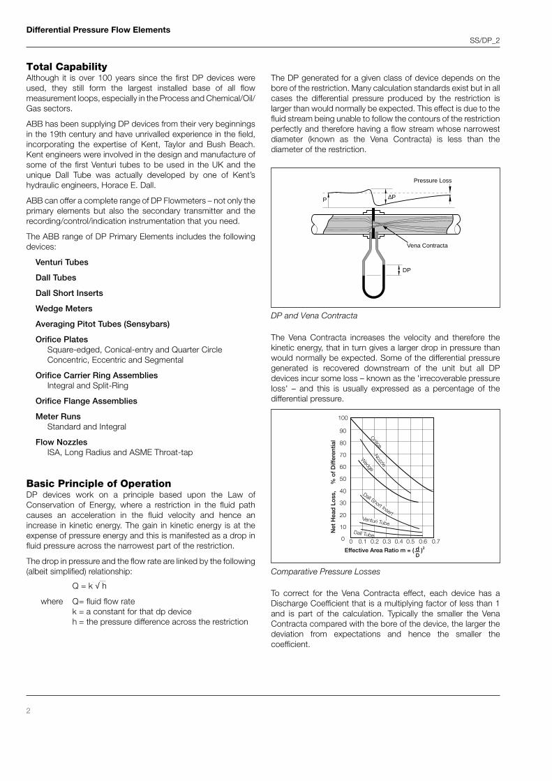
The DP generated for a given class of device depends on thebore of the restriction. Many calculation standards exist but in allcases the differential pressure produced by the restriction islarger than would normally be expected. This effect is due to thefluid stream being unable to follow the contours of the restrictionperfectly and therefore having a flow stream whose narrowestdiameter (known as the Vena Contracta) is less than thediameter of the restriction.
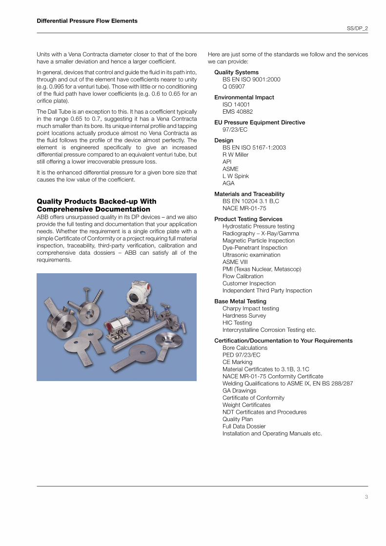
The Vena Contracta increases the velocity and therefore thekinetic energy, that in turn gives a larger drop in pressure thanwould normally be expected. Some of the differential pressuregenerated is recovered downstream of the unit but all DPdevices incur some loss – known as the 'irrecoverable pressureloss' – and this is usually expressed as a percentage of thedifferential pressure.
To correct for the Vena Contracta effect, each device has aDischarge Coefficient that is a multiplying factor of less than 1and is part of the calculation. Typically the smaller the VenaContracta compared with the bore of the device, the larger thedeviation from expectations and hence the smaller thecoefficient.
00
10
20
30
40
50
60
70
80
90
100
Net
Hea
d L
oss
, %
of
Diff
eren
tial
0.1 0.2 0.3 0.4 0.5 0.6
Effective Area Ratio m = ( d )2
OrificeNozzle
Dall Short InsertVenturi Tube
Dall Tube0.7
D
Wedge
DP
Vena Contracta
∆P
Pressure Loss
P
DP and Vena Contracta
Comparative Pressure Losses
Q = k √ h
where Q= fluid flow ratek = a constant for that dp deviceh = the pressure difference across the restriction
Differential Pressure Flow ElementsSS/DP_2
3
Units with a Vena Contracta diameter closer to that of the borehave a smaller deviation and hence a larger coefficient.
In general, devices that control and guide the fluid in its path into,through and out of the element have coefficients nearer to unity(e.g. 0.995 for a venturi tube). Those with little or no conditioningof the fluid path have lower coefficients (e.g. 0.6 to 0.65 for anorifice plate).
The Dall Tube is an exception to this. It has a coefficient typicallyin the range 0.65 to 0.7, suggesting it has a Vena Contractamuch smaller than its bore. Its unique internal profile and tappingpoint locations actually produce almost no Vena Contracta asthe fluid follows the profile of the device almost perfectly. Theelement is engineered specifically to give an increaseddifferential pressure compared to an equivalent venturi tube, butstill offering a lower irrecoverable pressure loss.
It is the enhanced differential pressure for a given bore size thatcauses the low value of the coefficient.
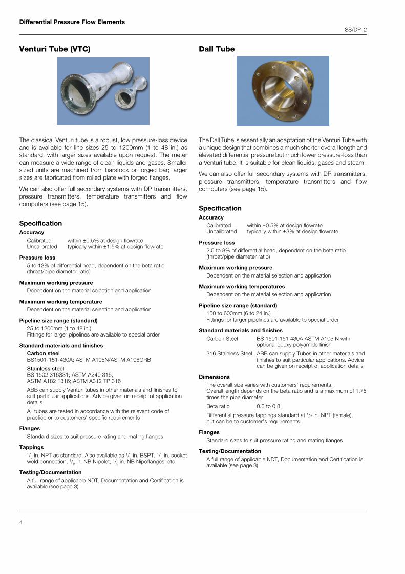
Quality Products Backed-up WithComprehensive DocumentationABB offers unsurpassed quality in its DP devices – and we alsoprovide the full testing and documentation that your applicationneeds. Whether the requirement is a single orifice plate with asimple Certificate of Conformity or a project requiring full materialinspection, traceability, third-party verification, calibration andcomprehensive data dossiers – ABB can satisfy all of therequirements.
Here are just some of the standards we follow and the serviceswe can provide:
Quality SystemsBS EN ISO 9001:2000Q 05907
Environmental ImpactISO 14001EMS 40882
EU Pressure Equipment Directive97/23/EC
DesignBS EN ISO 5167-1:2003R W MillerAPIASMEL W SpinkAGA
Materials and TraceabilityBS EN 10204 3.1 B,CNACE MR-01-75
Product Testing ServicesHydrostatic Pressure testingRadiography – X-Ray/GammaMagnetic Particle InspectionDye-Penetrant InspectionUltrasonic examinationASME VIIIPMI (Texas Nuclear, Metascop)Flow CalibrationCustomer InspectionIndependent Third Party Inspection
Base Metal TestingCharpy Impact testingHardness SurveyHIC TestingIntercrystalline Corrosion Testing etc.
Certification/Documentation to Your RequirementsBore CalculationsPED 97/23/ECCE MarkingMaterial Certificates to 3.1B, 3.1CNACE MR-01-75 Conformity CertificateWelding Qualifications to ASME IX, EN BS 288/287GA DrawingsCertificate of ConformityWeight CertificatesNDT Certificates and ProceduresQuality PlanFull Data DossierInstallation and Operating Manuals etc.
Differential Pressure Flow ElementsSS/DP_2
4
Venturi Tube (VTC)
The Dall Tube is essentially an adaptation of the Venturi Tube witha unique design that combines a much shorter overall length andelevated differential pressure but much lower pressure-loss thana Venturi tube. It is suitable for clean liquids, gases and steam.
We can also offer full secondary systems with DP transmitters,pressure transmitters, temperature transmitters and flowcomputers (see page 15).
SpecificationAccuracy
Calibrated within ±0.5% at design flowrateUncalibrated typically within ±3% at design flowrate
Pressure loss2.5 to 8% of differential head, dependent on the beta ratio(throat/pipe diameter ratio)
Maximum working pressureDependent on the material selection and application
Maximum working temperaturesDependent on the material selection and application
Pipeline size range (standard)150 to 600mm (6 to 24 in.)Fittings for larger pipelines are available to special order
Standard materials and finishesCarbon Steel BS 1501 151 430A ASTM A105 N with
optional epoxy polyamide finish
316 Stainless Steel ABB can supply Tubes in other materials andfinishes to suit particular applications. Advicecan be given on receipt of application details
DimensionsThe overall size varies with customers' requirements.Overall length depends on the beta ratio and is a maximum of 1.75times the pipe diameter
Beta ratio 0.3 to 0.8
Differential pressure tappings standard at 1/2 in. NPT (female),but can be to customer’s requirements
FlangesStandard sizes to suit pressure rating and mating flanges
Testing/DocumentationA full range of applicable NDT, Documentation and Certification isavailable (see page 3)
The classical Venturi tube is a robust, low pressure-loss deviceand is available for line sizes 25 to 1200mm (1 to 48 in.) asstandard, with larger sizes available upon request. The metercan measure a wide range of clean liquids and gases. Smallersized units are machined from barstock or forged bar; largersizes are fabricated from rolled plate with forged flanges.
We can also offer full secondary systems with DP transmitters,pressure transmitters, temperature transmitters and flowcomputers (see page 15).
SpecificationAccuracy
Calibrated within ±0.5% at design flowrateUncalibrated typically within ±1.5% at design flowrate
Pressure loss5 to 12% of differential head, dependent on the beta ratio(throat/pipe diameter ratio)
Maximum working pressureDependent on the material selection and application
Maximum working temperatureDependent on the material selection and application
Pipeline size range (standard)25 to 1200mm (1 to 48 in.)Fittings for larger pipelines are available to special order
Standard materials and finishesCarbon steelBS1501-151-430A; ASTM A105N/ASTM A106GRB
ABB can supply Venturi tubes in other materials and finishes tosuit particular applications. Advice given on receipt of applicationdetails
All tubes are tested in accordance with the relevant code ofpractice or to customers' specific requirements
FlangesStandard sizes to suit pressure rating and mating flanges
Tappings1/2 in. NPT as standard. Also available as 1/2 in. BSPT, 1/2 in. socketweld connection, 1/2 in. NB Nipolet, 1/2 in. NB Nipoflanges, etc.
Testing/DocumentationA full range of applicable NDT, Documentation and Certification isavailable (see page 3)
Dall Tube
Differential Pressure Flow ElementsSS/DP_2
5
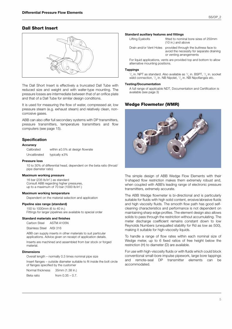
Dall Short Insert
The Dall Short Insert is effectively a truncated Dall Tube withreduced size and weight and with wafer-type mounting. Thepressure losses are intermediate between that of an orifice plateand that of a Dall Tube for similar design conditions.
It is used for measuring the flow of water, compressed air, lowpressure steam (e.g. exhaust steam) and relatively clean, non-corrosive gases.
ABB can also offer full secondary systems with DP transmitters,pressure transmitters, temperature transmitters and flowcomputers (see page 15).
SpecificationAccuracy
Calibrated within ±0.5% at design flowrate
Uncalibrated typically ±3%
Pressure loss10 to 30% of differential head, dependent on the beta ratio (throat/pipe diameter ratio)
Maximum working pressure16 bar (235 lb/in2.) as standardConsult ABB regarding higher pressures,up to a maximum of 70 bar (1000 lb/in2.)
Maximum working temperatureDependent on the material selection and application
Pipeline size range (standard)150 to 1000mm (6 to 40 in.)Fittings for larger pipelines are available to special order
Standard materials and finishesCarbon Steel ASTM A105N
Stainless Steel AISI 316
ABB can supply inserts in other materials to suit particularapplications. Advice given on receipt of application details.
Inserts are machined and assembled from bar stock or forgedmaterial.
DimensionsOverall length – normally 0.3 times nominal pipe size
Insert flanges – outside diameter suitable to fit inside the bolt circleof flanges specified by the customer
Normal thickness 35mm (1.38 in.)
Beta ratio from 0.35 – 0.7.
Standard auxiliary features and fittingsLifting Eyebolts fitted to nominal bore sizes of 250mm
(10 in.) and above
Drain and/or Vent Holes provided through the buttress face toavoid the necessity for separate drainingor venting arrangements
For liquid applications, vents are provided top and bottom to allowalternative mounting positions.
Tappings1/2 in. NPT as standard. Also available as 1/2 in. BSPT, 1/2 in. socketweld connection, 1/2 in. NB Nipolet, 1/2 in. NB Nipoflanges etc.
Testing/DocumentationA full range of applicable NDT, Documentation and Certification isavailable (see page 3)
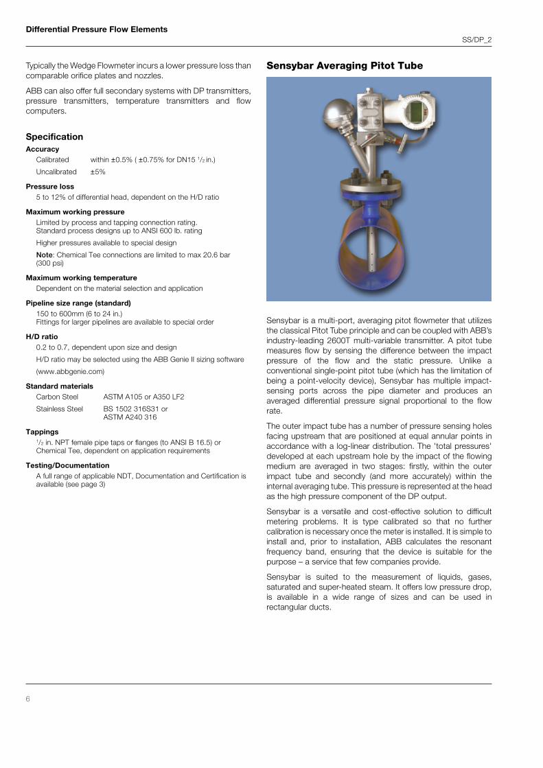
Wedge Flowmeter (WMR)
The simple design of ABB Wedge Flow Elements with theirV-shaped flow restriction makes them extremely robust and,when coupled with ABB’s leading range of electronic pressuretransmitters, extremely accurate.
The ABB Wedge flowmeter is bi-directional and is particularlysuitable for fluids with high solid content, erosive/abrasive fluidsand high viscosity fluids. The smooth flow path has good self-cleaning characteristics and performance is not dependent onmaintaining sharp edge profiles. The element design also allowssolids to pass through the restriction without accumulating. Themeter discharge coefficient remains constant down to lowReynolds Numbers (unequalled stability for Rd as low as 500),making it suitable for high-viscosity liquids.
To handle a range of flow rates within each nominal size ofWedge meter, up to 6 fixed ratios of free height below therestriction (H) to diameter (D) are available.
For use with high-viscosity fluids or with fluids which could blockconventional small-bore impulse pipework, large bore tappingsand remote-seal DP transmitter elements can beaccommodated.
Differential Pressure Flow ElementsSS/DP_2
6
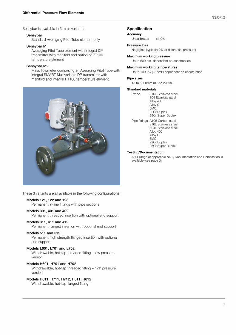
Sensybar is a multi-port, averaging pitot flowmeter that utilizesthe classical Pitot Tube principle and can be coupled with ABB’sindustry-leading 2600T multi-variable transmitter. A pitot tubemeasures flow by sensing the difference between the impactpressure of the flow and the static pressure. Unlike aconventional single-point pitot tube (which has the limitation ofbeing a point-velocity device), Sensybar has multiple impact-sensing ports across the pipe diameter and produces anaveraged differential pressure signal proportional to the flowrate.
The outer impact tube has a number of pressure sensing holesfacing upstream that are positioned at equal annular points inaccordance with a log-linear distribution. The 'total pressures'developed at each upstream hole by the impact of the flowingmedium are averaged in two stages: firstly, within the outerimpact tube and secondly (and more accurately) within theinternal averaging tube. This pressure is represented at the headas the high pressure component of the DP output.
Sensybar is a versatile and cost-effective solution to difficultmetering problems. It is type calibrated so that no furthercalibration is necessary once the meter is installed. It is simple toinstall and, prior to installation, ABB calculates the resonantfrequency band, ensuring that the device is suitable for thepurpose – a service that few companies provide.
Sensybar is suited to the measurement of liquids, gases,saturated and super-heated steam. It offers low pressure drop,is available in a wide range of sizes and can be used inrectangular ducts.
Typically the Wedge Flowmeter incurs a lower pressure loss thancomparable orifice plates and nozzles.
ABB can also offer full secondary systems with DP transmitters,pressure transmitters, temperature transmitters and flowcomputers.
SpecificationAccuracy
Calibrated within ±0.5% ( ±0.75% for DN15 1/2 in.)
Uncalibrated ±5%
Pressure loss5 to 12% of differential head, dependent on the H/D ratio
Maximum working pressureLimited by process and tapping connection rating.Standard process designs up to ANSI 600 lb. rating
Higher pressures available to special design
Note: Chemical Tee connections are limited to max 20.6 bar(300 psi)
Maximum working temperatureDependent on the material selection and application
Pipeline size range (standard)150 to 600mm (6 to 24 in.)Fittings for larger pipelines are available to special order
H/D ratio0.2 to 0.7, dependent upon size and design
H/D ratio may be selected using the ABB Genie II sizing software
(www.abbgenie.com)
Standard materialsCarbon Steel ASTM A105 or A350 LF2
Stainless Steel BS 1502 316S31 orASTM A240 316
Tappings1/2 in. NPT female pipe taps or flanges (to ANSI B 16.5) orChemical Tee, dependent on application requirements
Testing/DocumentationA full range of applicable NDT, Documentation and Certification isavailable (see page 3)
Sensybar Averaging Pitot Tube
Differential Pressure Flow ElementsSS/DP_2
7
Sensybar is available in 3 main variants:
SensybarStandard Averaging Pitot Tube element only
Sensybar MAveraging Pitot Tube element with integral DPtransmitter with manifold and option of PT100temperature element
Sensybar M2Mass flowmeter comprising an Averaging Pitot Tube withintegral SMART Multivariable DP transmitter withmanifold and integral PT100 temperature element.
These 3 variants are all available in the following configurations:
Models 121, 122 and 123Permanent in-line fittings with pipe sections
Models 301, 401 and 402Permanent threaded insertion with optional end support
Models 311, 411 and 412Permanent flanged insertion with optional end support
Models 511 and 512Permanent high strength flanged insertion with optionalend support
Testing/DocumentationA full range of applicable NDT, Documentation and Certification isavailable (see page 3)
Differential Pressure Flow ElementsSS/DP_2
8
Orifice PlatesThe ABB range extends from standard size orifice plates, someof which are available on a next day delivery if required, throughorifice carrier assemblies to custom-engineered meteringsections, such as those utilized in fiscal gas flow, incorporatingtemperature and pressure compensation elements. The platesare usually supplied with a data tab welded to thecircumference. On this tab can be engraved the Tag Numberplate bore, etc., which is visible without removing the plate fromthe line.
A variety of tapping point configurations are used:
D and D/2 tapsHere the tappings are located in the pipe wall. Thecentreline of the upstream tapping is one pipe diameter(D) from the upstream face of the plate and thedownstream tapping is half the pipe diameter (D/2 or1/2D) from the downstream face.
Flange tapsHere the tappings are located in the pipe flanges. Thecentreline of the upstream tapping is 25.4 mm (1 in.)from the upstream face of the plate and similarly thedownstream tapping is 25.4 mm (1 in.) from thedownstream face.
Corner tapsCorner Taps are also located in the pipe flanges but theircentrelines break into the pipe exactly at the cornersformed by the plate faces and the pipe walls.
ABB offers three types of concentric orifice plate to cover a widerange of applications designated CSE, CCL and CQC.
Concentric Square Edge Type (CSE)Type CSE plates are used to measure the flowrate of clean, low-viscosity liquids, gases and dry steam at Reynolds Numbers in
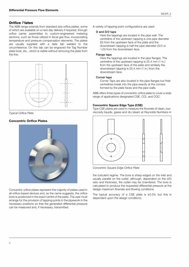
Concentric orifice plates represent the majority of plates used inall orifice-based devices and, as the name suggests, the orificebore is positioned in the exact centre of the plate. The user mustarrange for the provision of tapping points in the pipework in thenecessary positions so that the generated differential pressurecan be measured and, if necessary, transmitted.
Concentric Orifice Plates
Typical Orifice Plate
the turbulent regime. The bore is sharp-edged on the inlet andusually parallel on the outlet, although, dependent on the d/Dratio and thickness, the outlet may be chamfered. The bore iscalculated to produce the requested differential pressure at thedesign maximum flowrate and flowing conditions.
The typical accuracy of a CSE plate is ±0.5% but this isdependent upon the design conditions.
Concentric Square Edge Orifice Plate
Differential Pressure Flow ElementsSS/DP_2
9
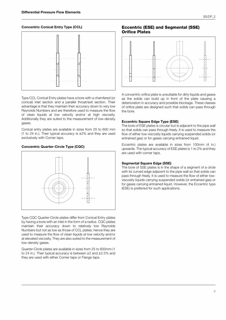
Concentric Conical Entry Type (CCL)
Concentric Quarter-Circle Type (CQC)
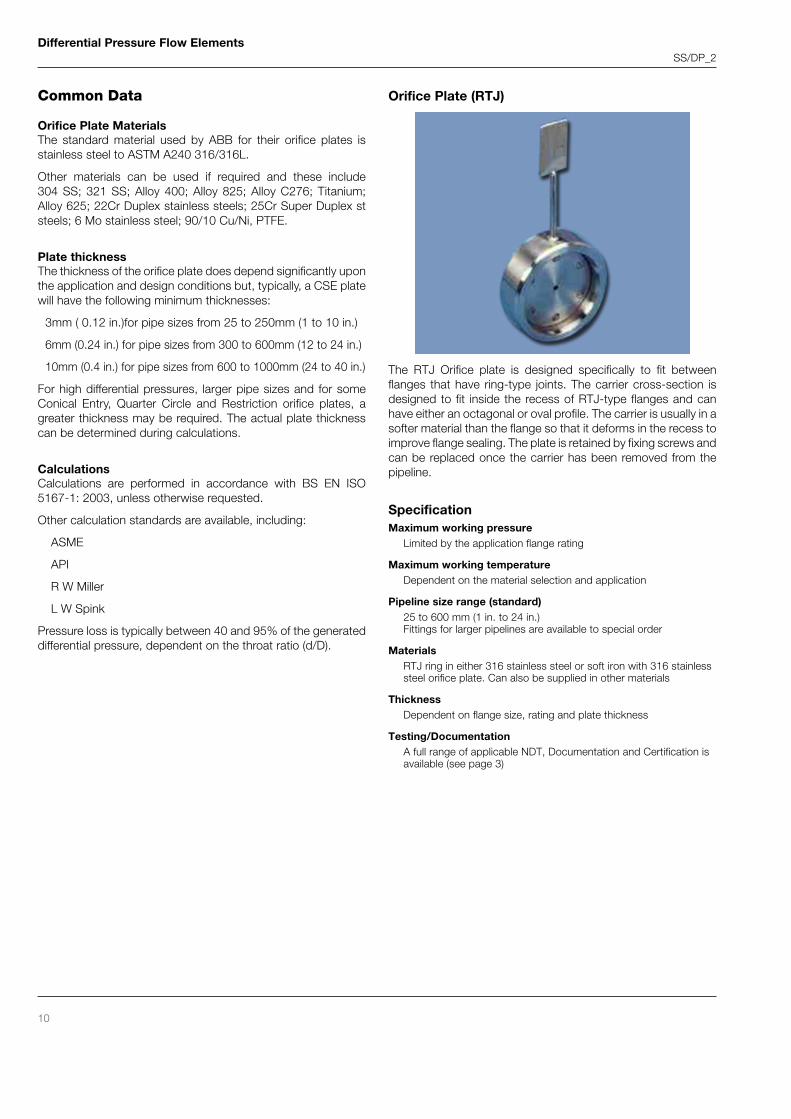
A concentric orifice plate is unsuitable for dirty liquids and gasesas the solids can build up in front of the plate causing adeterioration in accuracy and possible blockage. These classesof orifice plate are designed such that solids can pass throughthe bore.
Eccentric Square Edge Type (ESE)The bore of ESE plates is circular but is adjacent to the pipe wallso that solids can pass through freely. It is used to measure theflow of either low-viscosity liquids carrying suspended solids (orentrained gas) or for gases carrying entrained liquid.
Eccentric plates are available in sizes from 100mm (4 in.)upwards. The typical accuracy of ESE plates is 1 to 2% and theyare used with corner taps.
Segmental Square Edge (SSE)The bore of SSE plates is in the shape of a segment of a circlewith its curved edge adjacent to the pipe wall so that solids canpass through freely. It is used to measure the flow of either low-viscosity liquids carrying suspended solids (or entrained gas) orfor gases carrying entrained liquid. However, the Eccentric type(ESE) is preferred for such applications.
Eccentric (ESE) and Segmental (SSE)Orifice Plates
Type CQC Quarter-Circle plates differ from Conical Entry platesby having a bore with an inlet in the form of a radius. CQC platesmaintain their accuracy down to relatively low ReynoldsNumbers but not as low as those of CCL plates; hence they areused to measure the flow of clean liquids at low velocity and/orat elevated viscosity. They are also suited to the measurement oflow-density gases.
Quarter-Circle plates are available in sizes from 25 to 600mm (1to 24 in.). Their typical accuracy is between ±2 and ±2.5% andthey are used with either Corner taps or Flange taps.
Type CCL Conical Entry plates have a bore with a chamfered (orconical) inlet section and a parallel throat/exit section. Theiradvantage is that they maintain their accuracy down to very lowReynolds Numbers and are therefore used to measure the flowof clean liquids at low velocity and/or at high viscosity.Additionally they are suited to the measurement of low-densitygases.
Conical entry plates are available in sizes from 25 to 600 mm(1 to 24 in.). Their typical accuracy is ±2% and they are usedexclusively with Corner taps.
Differential Pressure Flow ElementsSS/DP_2
10
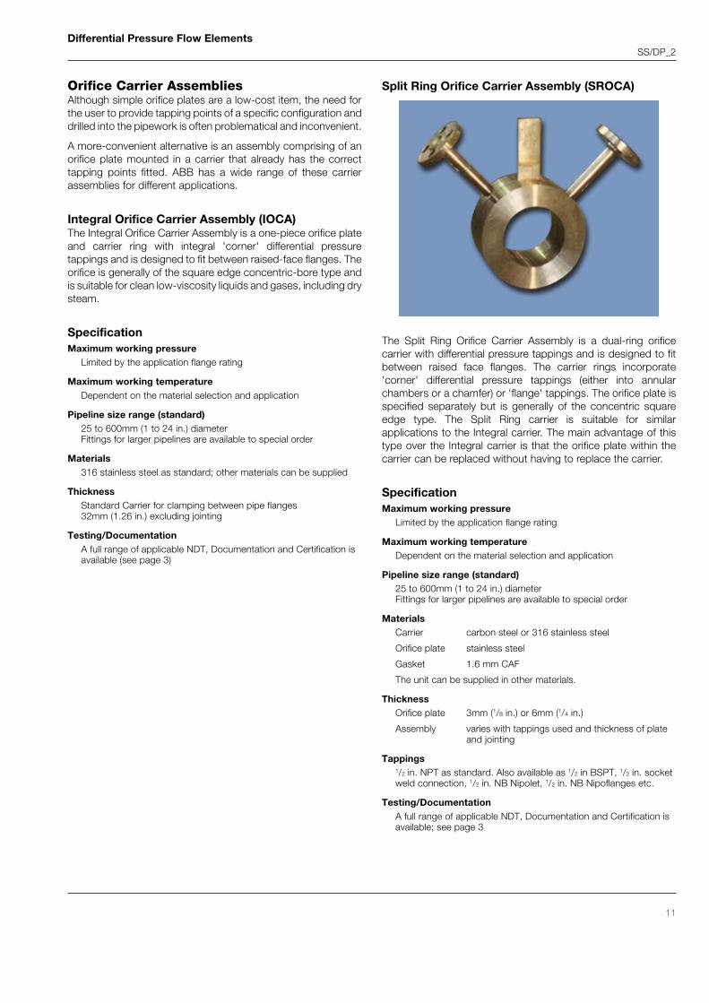
The RTJ Orifice plate is designed specifically to fit betweenflanges that have ring-type joints. The carrier cross-section isdesigned to fit inside the recess of RTJ-type flanges and canhave either an octagonal or oval profile. The carrier is usually in asofter material than the flange so that it deforms in the recess toimprove flange sealing. The plate is retained by fixing screws andcan be replaced once the carrier has been removed from thepipeline.
SpecificationMaximum working pressure
Limited by the application flange rating
Maximum working temperatureDependent on the material selection and application
Pipeline size range (standard)25 to 600 mm (1 in. to 24 in.)Fittings for larger pipelines are available to special order
MaterialsRTJ ring in either 316 stainless steel or soft iron with 316 stainlesssteel orifice plate. Can also be supplied in other materials
ThicknessDependent on flange size, rating and plate thickness
Testing/DocumentationA full range of applicable NDT, Documentation and Certification isavailable (see page 3)
Common Data
Orifice Plate MaterialsThe standard material used by ABB for their orifice plates isstainless steel to ASTM A240 316/316L.
Other materials can be used if required and these include304 SS; 321 SS; Alloy 400; Alloy 825; Alloy C276; Titanium;Alloy 625; 22Cr Duplex stainless steels; 25Cr Super Duplex ststeels; 6 Mo stainless steel; 90/10 Cu/Ni, PTFE.
Plate thicknessThe thickness of the orifice plate does depend significantly uponthe application and design conditions but, typically, a CSE platewill have the following minimum thicknesses:
3mm ( 0.12 in.)for pipe sizes from 25 to 250mm (1 to 10 in.)
6mm (0.24 in.) for pipe sizes from 300 to 600mm (12 to 24 in.)
10mm (0.4 in.) for pipe sizes from 600 to 1000mm (24 to 40 in.)
For high differential pressures, larger pipe sizes and for someConical Entry, Quarter Circle and Restriction orifice plates, agreater thickness may be required. The actual plate thicknesscan be determined during calculations.
CalculationsCalculations are performed in accordance with BS EN ISO5167-1: 2003, unless otherwise requested.
Other calculation standards are available, including:
ASME
API
R W Miller
L W Spink
Pressure loss is typically between 40 and 95% of the generateddifferential pressure, dependent on the throat ratio (d/D).
Orifice Plate (RTJ)
Differential Pressure Flow ElementsSS/DP_2
11
Orifice Carrier AssembliesAlthough simple orifice plates are a low-cost item, the need forthe user to provide tapping points of a specific configuration anddrilled into the pipework is often problematical and inconvenient.
A more-convenient alternative is an assembly comprising of anorifice plate mounted in a carrier that already has the correcttapping points fitted. ABB has a wide range of these carrierassemblies for different applications.
Integral Orifice Carrier Assembly (IOCA)The Integral Orifice Carrier Assembly is a one-piece orifice plateand carrier ring with integral 'corner' differential pressuretappings and is designed to fit between raised-face flanges. Theorifice is generally of the square edge concentric-bore type andis suitable for clean low-viscosity liquids and gases, including drysteam.
SpecificationMaximum working pressure
Limited by the application flange rating
Maximum working temperatureDependent on the material selection and application
Pipeline size range (standard)25 to 600mm (1 to 24 in.) diameterFittings for larger pipelines are available to special order
Materials316 stainless steel as standard; other materials can be supplied
ThicknessStandard Carrier for clamping between pipe flanges32mm (1.26 in.) excluding jointing
Testing/DocumentationA full range of applicable NDT, Documentation and Certification isavailable (see page 3)
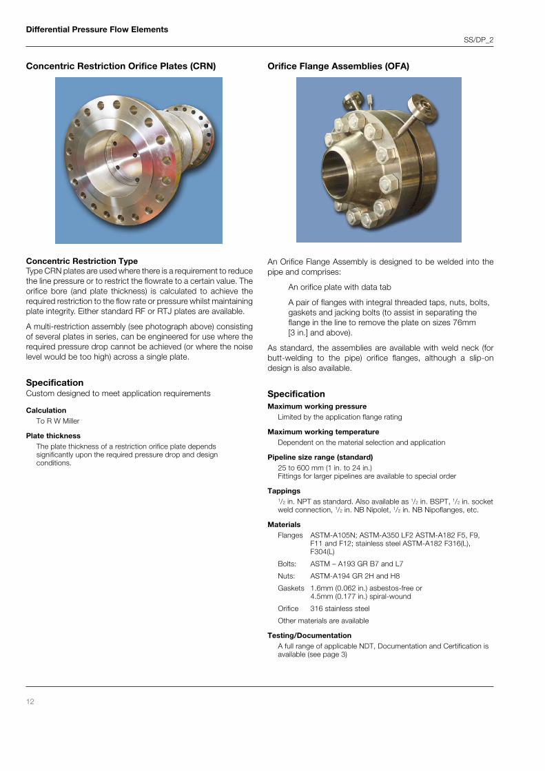
Split Ring Orifice Carrier Assembly (SROCA)
The Split Ring Orifice Carrier Assembly is a dual-ring orificecarrier with differential pressure tappings and is designed to fitbetween raised face flanges. The carrier rings incorporate'corner' differential pressure tappings (either into annularchambers or a chamfer) or 'flange' tappings. The orifice plate isspecified separately but is generally of the concentric squareedge type. The Split Ring carrier is suitable for similarapplications to the Integral carrier. The main advantage of thistype over the Integral carrier is that the orifice plate within thecarrier can be replaced without having to replace the carrier.
SpecificationMaximum working pressure
Limited by the application flange rating
Maximum working temperatureDependent on the material selection and application
Pipeline size range (standard)25 to 600mm (1 to 24 in.) diameterFittings for larger pipelines are available to special order
MaterialsCarrier carbon steel or 316 stainless steel
Orifice plate stainless steel
Gasket 1.6 mm CAF
The unit can be supplied in other materials.
ThicknessOrifice plate 3mm (1/8 in.) or 6mm (1/4 in.)
Assembly varies with tappings used and thickness of plateand jointing
Tappings1/2 in. NPT as standard. Also available as 1/2 in BSPT, 1/2 in. socketweld connection, 1/2 in. NB Nipolet, 1/2 in. NB Nipoflanges etc.
Testing/DocumentationA full range of applicable NDT, Documentation and Certification isavailable; see page 3
Concentric Restriction TypeType CRN plates are used where there is a requirement to reducethe line pressure or to restrict the flowrate to a certain value. Theorifice bore (and plate thickness) is calculated to achieve therequired restriction to the flow rate or pressure whilst maintainingplate integrity. Either standard RF or RTJ plates are available.
A multi-restriction assembly (see photograph above) consistingof several plates in series, can be engineered for use where therequired pressure drop cannot be achieved (or where the noiselevel would be too high) across a single plate.
SpecificationCustom designed to meet application requirements
CalculationTo R W Miller
Plate thicknessThe plate thickness of a restriction orifice plate dependssignificantly upon the required pressure drop and designconditions.
An Orifice Flange Assembly is designed to be welded into thepipe and comprises:
An orifice plate with data tab
A pair of flanges with integral threaded taps, nuts, bolts,gaskets and jacking bolts (to assist in separating theflange in the line to remove the plate on sizes 76mm[3 in.] and above).
As standard, the assemblies are available with weld neck (forbutt-welding to the pipe) orifice flanges, although a slip-ondesign is also available.
SpecificationMaximum working pressure
Limited by the application flange rating
Maximum working temperatureDependent on the material selection and application
Pipeline size range (standard)25 to 600 mm (1 in. to 24 in.)Fittings for larger pipelines are available to special order
Tappings1/2 in. NPT as standard. Also available as 1/2 in. BSPT, 1/2 in. socketweld connection, 1/2 in. NB Nipolet, 1/2 in. NB Nipoflanges, etc.
Testing/DocumentationA full range of applicable NDT, Documentation and Certification isavailable (see page 3)
Differential Pressure Flow ElementsSS/DP_2
13
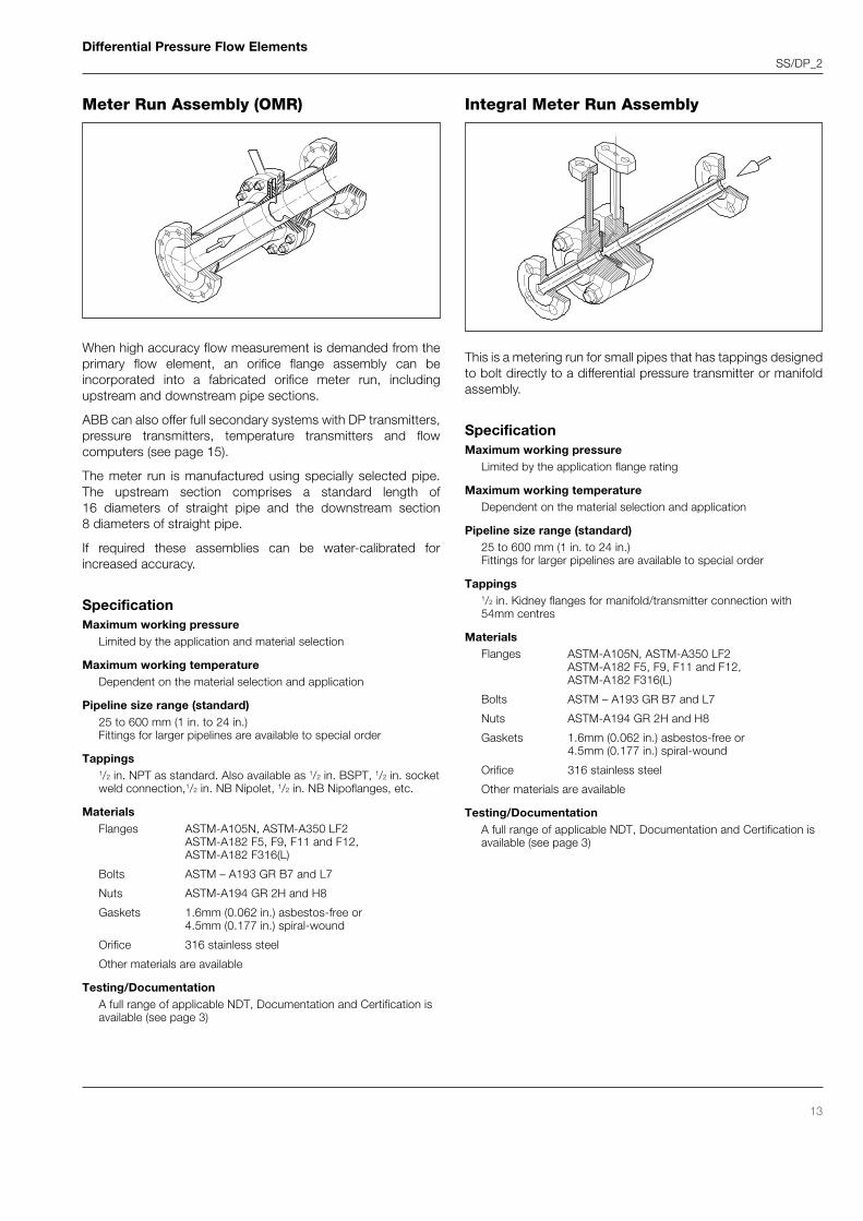
Meter Run Assembly (OMR) Integral Meter Run Assembly
When high accuracy flow measurement is demanded from theprimary flow element, an orifice flange assembly can beincorporated into a fabricated orifice meter run, includingupstream and downstream pipe sections.
ABB can also offer full secondary systems with DP transmitters,pressure transmitters, temperature transmitters and flowcomputers (see page 15).
The meter run is manufactured using specially selected pipe.The upstream section comprises a standard length of16 diameters of straight pipe and the downstream section8 diameters of straight pipe.
If required these assemblies can be water-calibrated forincreased accuracy.
SpecificationMaximum working pressure
Limited by the application and material selection
Maximum working temperatureDependent on the material selection and application
Pipeline size range (standard)25 to 600 mm (1 in. to 24 in.)Fittings for larger pipelines are available to special order
Tappings1/2 in. NPT as standard. Also available as 1/2 in. BSPT, 1/2 in. socketweld connection,1/2 in. NB Nipolet, 1/2 in. NB Nipoflanges, etc.
Testing/DocumentationA full range of applicable NDT, Documentation and Certification isavailable (see page 3)
Differential Pressure Flow ElementsSS/DP_2
14
SpecificationMaximum working pressure
Limited by the application and material selection
Maximum working temperatureDependent on the material selection and application
Pipeline size range (standard)25 to 600 mm (1 in. to 24 in.)Fittings for larger pipelines are available to special order
Tappings1/2 in. NPT as standard. Also available as 1/2 in. BSPT, 1/2 in. socketweld connection, 1/2 in. NB Nipolet, 1/2 in. NB Nipoflanges, etc.
Materials316 and 316L stainless steelOther materials (including high-temperature alloys) are available
Testing/DocumentationA full range of applicable NDT, Documentation and Certification isavailable (see page 3)
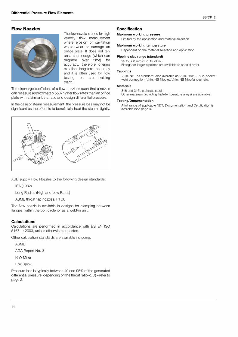
Flow NozzlesThe flow nozzle is used for highvelocity flow measurementwhere erosion or cavitationwould wear or damage anorifice plate. It does not relyon a sharp edge (which candegrade over time) foraccuracy, therefore offeringexcellent long-term accuracyand it is often used for flowtesting on steam-raisingplant.
The discharge coefficient of a flow nozzle is such that a nozzlecan measure approximately 55% higher flow rates than an orificeplate with a similar beta ratio and design differential pressure.
In the case of steam measurement, the pressure loss may not besignificant as the effect is to beneficially heat the steam slightly.
ABB supply Flow Nozzles to the following design standards:
ISA (1932)
Long Radius (High and Low Rates)
ASME throat tap nozzles. PTC6
The flow nozzle is available in designs for clamping betweenflanges (within the bolt circle )or as a weld-in unit.
CalculationsCalculations are performed in accordance with BS EN ISO5167-1: 2003, unless otherwise requested.
Other calculation standards are available including:
ASME
AGA Report No. 3
R W Miller
L W Spink
Pressure loss is typically between 40 and 95% of the generateddifferential pressure, depending on the throat ratio (d/D) – refer topage 2.
Differential Pressure Flow ElementsSS/DP_2
15
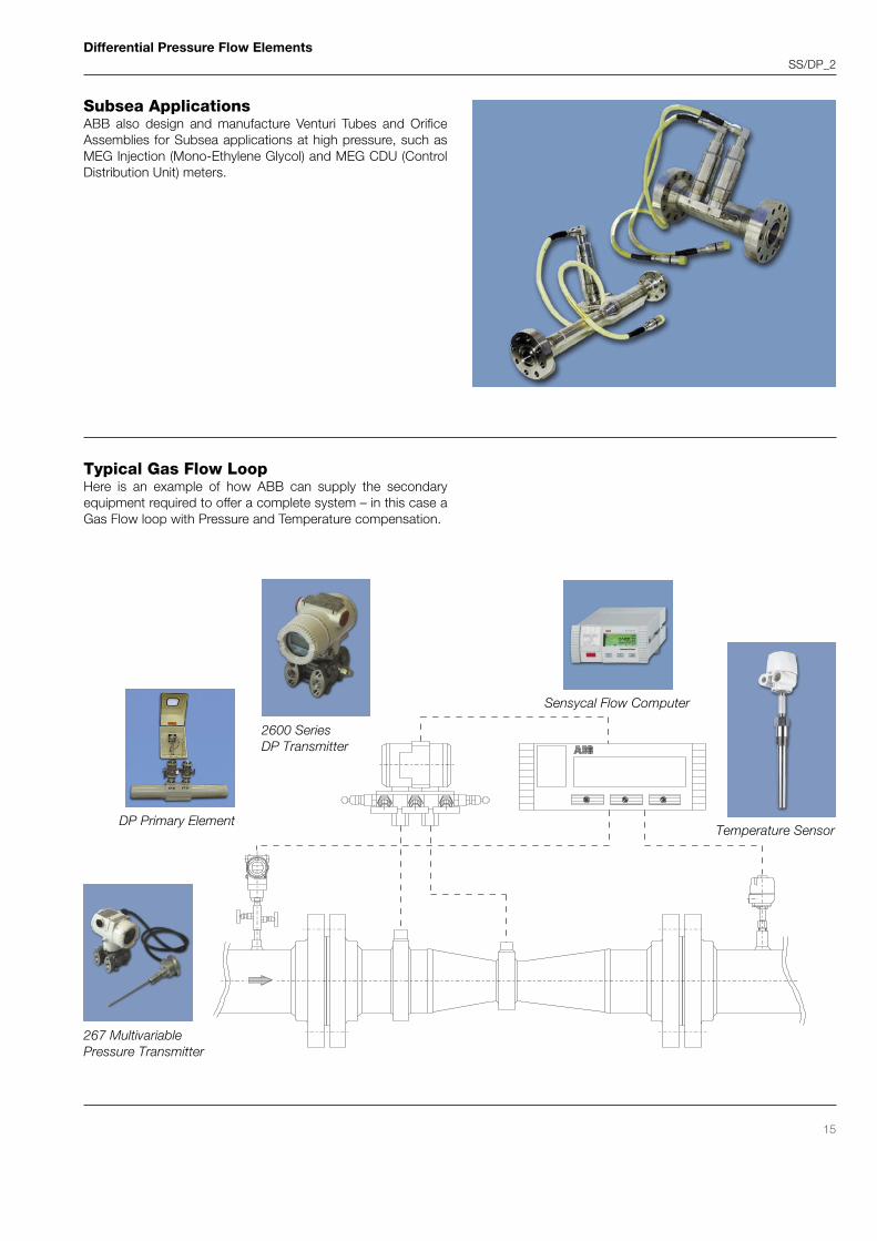
Typical Gas Flow LoopHere is an example of how ABB can supply the secondaryequipment required to offer a complete system – in this case aGas Flow loop with Pressure and Temperature compensation.
DP Primary Element
2600 SeriesDP Transmitter
Temperature Sensor
267 MultivariablePressure Transmitter
Subsea ApplicationsABB also design and manufacture Venturi Tubes and OrificeAssemblies for Subsea applications at high pressure, such asMEG Injection (Mono-Ethylene Glycol) and MEG CDU (ControlDistribution Unit) meters.


![[PPT]No Slide Title - Wikispacesptec107.wikispaces.com/file/view/Flow_Measurement.ppt · Web viewFlange Taps Corner Taps Radius Taps Vena-Contracta Taps Pipe Taps Multivariable Pressure](https://static.documents.pub/doc/80x56/5ad6f9207f8b9a32618bb97e/pptno-slide-title-viewflange-taps-corner-taps-radius-taps-vena-contracta-taps.jpg)


