1146 J. Opt. Soc. Am. A/Vol. 23, No. 5 /May 2006 Boyer et al.
Diffraction theory: application of the fast Fourierfactorization to cylindrical devices with
arbitrary cross section lighted in conical mounting
Philippe Boyer, Evgeny Popov, Michel Nevière, and Gilles Renversez
Institut Fresnel, Case 161, Unité Mixte de Recherche Associée au Centre National de la Recherche Scientifique(UMR 6133), Université Paul Cézanne Aix-Marseille III, et Université de Provence, Faculté des Sciences et Techniques
de St. Jérôme, Avenue Escadrille Normandie Niémen, 13397 Marseille Cedex 20, France
Received May 2, 2005; revised October 7, 2005; accepted October 10, 2005; posted November 16, 2005 (Doc. ID 61886)
. INTRODUCTIONylindrical devices commonly appear in diffraction andropagation theory, and their interest has recently in-reased with the advent of microstructured optical fibersMOFs).1 An efficient method called the multipole methodMM) has already been developed to study devices com-osed of cylindrical inclusions.1–3 Nevertheless, it has ateast two major limitations: All the inclusions must be in-luded in nonoverlapping circles and the refractive indexf the matrix containing the inclusions must be homoge-eous. In addition, the reflection matrix relating the inci-ent and the scattered field for each individual inclusionust be obtained by other means in the case of a noncir-
ular inclusion or inhomogeneous circular inclusion. Inhat follows, we present the application of the fast Fou-
ier factorization (FFF) method to diffraction theory. Thisew method has none of the known limitations of theM. Briefly, the FFF method rewrites the Maxwell equa-
ions through the use of a Fourier series. Although an iso-ated cylindrical object is a priori nonperiodic, it becomes� periodic with respect to the polar angle � when it isescribed in cylindrical coordinates. This periodicity al-ows us to describe both the electromagnetic field and theiffracting object in terms of a Fourier series. As was pre-iously done in grating theory,4 it is now possible to re-uce the Maxwell equations to a first-order differentialet that must be numerically integrated. Of course theumerical treatment requires truncating the Fourier se-ies of the field, a process that has created great numeri-al problems for decades but recently received a solutionhrough what is now called the FFF method. In a recentaper5 we proved that such a method was able to give fast
onverging results when a cylindrical object was illumi-ated under TM polarization. The aim of the present pa-er is to extend the theory to the most general case inhich the diffraction device is illuminated with a fieldropagating outside the cross-section plane of the device,hich leads to a full vectorial problem that does not re-uce to the two classical TE and TM cases of polariza-ions. Moreover, the propagation equations will be derivedn anisotropic media to open a way to resolve the diffrac-ion problem of a wave by an arbitrary cylinder made ofn arbitrary (lossy or lossless) anisotropic medium. Inections 2 and 3 we present the FFF principles to obtainhe set of differential equations defined in the area wherehe diffracting device locates. In Section 4 we discuss theomplete solution of the diffracting problem in the case ofn isotropic medium. In some cases, the diffracting objects invariant by a rotation of angle T=2� /NT (NT is theumber of subperiods of the 2� range). In Section 5 theumerical theory is adapted to take into account this sub-eriodicity on the T range of the polar angle coordinate �.inally, we validate the numerical implementation of ourethod with the well-established MM (Refs. 2 and 3)
hrough several examples including the excitation of theundamental mode of a six-hole MOF; we also discussome aspects of the numerical efficiency and accuracy ofhe FFF method.
. PRESENTATION OF THE PROBLEMe consider a cylindrical object described in both a Car-
esian coordinate system Oxyz with �ex ,ey ,ez� unit vec-ors and in cylindrical coordinates r ,� ,z with �e ,e ,e � as
r � z
006 Optical Society of America
urt2Twtgfidpraitdstta2or
to�
seo
i=wickctpt
ivnsfiaa
Ffisp
Fo
Fa
Fta
Boyer et al. Vol. 23, No. 5 /May 2006/J. Opt. Soc. Am. A 1147
nit vectors. Its surface �S� is defined by an arbitrary di-ectrix located in the cross-section plane �Oxy� containinghe origin as shown in Fig. 1 or outside the origin (see Fig.). Generatrices are straight lines parallel to the z axis.he equation of the directrix is f�r ,��=0 or r=g���, inhich f and g are given functions. The surface �S� divides
he space into two regions. The first one, the internal re-ion denoted int, is contained inside the surface and islled with a linear, inhomogeneous and anisotropic me-ium, dielectric or conducting (nonmagnetic), and its com-lex permittivity tensor is denoted �int
��r ,��. The secondegion, denoted ext, is the outside region and is filled withhomogeneous exterior medium, and its real permittivity
s denoted �ext. The present method requires that we in-roduce three areas defined by two circular cylinders withirectrix Cmin and Cmax. The directrix Cmin is the in-cribed circle of the directrix of surface �S�, and Cmax ishe circumscribed circle (see Fig. 1). The area included be-ween both circular cylinders is called the modulatedrea. Inside this area the permittivity is described by a� periodic with respect to � tensor ���r ,��. Unless definedtherwise, both lower-case and capital letters in bold rep-esent vectors.
An incident plane wave with wave vector kext withransverse component kt,ext and z component �0 fallsn the device (Fig. 3). We introduce two angles:
= �−e ,k � and �= �k ,k ���−� /2 ,� /2�. We as-
ig. 1. Cross section of an arbitrary shaped cylindrical objectlled with an anisotropic and inhomogeneous media and de-cribed by a directrix r=g��� containing the origin in the Oxylane and generatrices parallel to the z axis.
ig. 2. Same kind of arbitrary cross section as in Fig. 1 with therigin outside the directrix.
inc x t,ext t,ext ext
ume that the plane-wave components have a harmonicxp�−i�t� time dependence. Thus the incident vector fieldf E and H reads
�E�inc��r,�,z,t� = Ae exp�i��0z − �t��
� exp�ikt,extr cos�� − �inc − ���
H�inc��r,�,z,t� = Ah exp�i��0z − �t��
� exp�ikt,extr cos�� − �inc − ���� , �1�
n which �=2� /�0�0�0, �0=−kext sin���, kt,ext�kext
2−�02 with kext= �2� /�0���ext/�0 where �0 is the
avelength in vacuum. Moreover, the polarization of thencident electric field is defined by the azimuthal angle ontained in the plane perpendicular to the wave vectorext and with basic vectors �p1 ,p2� [p1 is chosen to be in-luded in the plane �kext,ez�, see Fig. 4]. The relation be-ween the E�inc� amplitude noted as Ae and the H�inc� am-litude noted as Ah with the incident wave vector readshanks to the Maxwell equations in homogeneous regions:
�Ae = �cos��p1 + sin��p2��E�inc��
Ah = −1
Z
kext
�kext�� Ae � with Z =
1
next�0
�0,
�2�
n which �E�inc�� and �kext� are the norms of their respectiveectors E�inc� and kext. If the permittivity is a complexumber, the cut of the square root next=��ext is then cho-en as the second bisector as explained in Ref. 6. The totaleld has the same time dependence as the incident wave,nd the invariance of the device with respect to z leads ton exp�i�0z� dependence. Moreover, the cylindrical coordi-
ig. 3. Incident wave vector in the exterior homogeneous regionnd notations.
ig. 4. Definitions and notations for the azimuthal angle ofhe incident electric field (p1 belongs to the plane defined by eznd k ).
ext
nstuc
3METnfitncictIta(FrttFd
Ai
1Apfbw
Ifettpgg
TT
ur
TpotL
O
Fthcbt
2Trscotc�jt�dws
1148 J. Opt. Soc. Am. A/Vol. 23, No. 5 /May 2006 Boyer et al.
ate system naturally implies a 2� periodicity with re-pect to �. In view of a numerical implementation of theheory, an electromagnetic and geometric quantity�r ,� ,z , t� will be represented by its Fourier series trun-ated to the Nth order:
u�r,�,z,t� = exp�i��0z − �t�� n=−N
+N
un�r�exp�in�� with un�r�
=1
2�
0
2�
u�r,��exp�− in��d�. �3�
. FAST FOURIER FACTORIZATIONETHOD IN CYLINDRICAL COORDINATES
XTENDED TO A CONICAL MOUNTINGhe aim of this work is to establish, in cylindrical coordi-ates, a set of equations satisfied by the electromagneticeld suitable for numerical computations. We make use ofhe recent progress in grating theory published under theame of fast Fourier factorization (FFF), but the case ofylindrical coordinates is not treated in the book describ-ng the method.4 The FFF method starts from the classi-al differential method7 with efficient improvements inhe factorizations rule concerning Fourier developments.n fact, we have to consider new factorization rules thatake into account the Fourier truncation of developmentsnd the discontinuities of any optogeometric quantitiesacross the diffracting surface). One of the key steps of theFF method is to find the correct formulation in the Fou-ier space of the product between �� and E in the constitu-ive relation that must be injected into the Maxwell equa-ions. Doing so, the Maxwell equations are restated in theourier space to obtain a set of coupled linear ordinaryifferential equations.
. Formulation of the Linear Relation between E and Dn a Truncated Fourier Space
. Factorization Ruless has been already treated in the paper concerning TMolarization,5 the FFF method consists in finding the bestormulation in a truncated Fourier space of the productetween the tensor ���r ,�� and E in the modulated regionhen we want to calculate D given by
D = ���r,��E. �4�
n fact, the function ���r ,�� is discontinuous across the sur-ace �S�. The mathematical basis of the FFF method wasstablished by Li8 with factorization rules that allow oneo obtain a solution of this problem. The first rule stateshat the Fourier components hn of the product h�x� of twoeriodic, piecewise-smooth bounded functions f�x� and�x� that are not discontinuous at the same value of x areiven by Laurent’s rule:
hn = �fg�n = m=−N
+N
fn−mgm. �5�
o simplify the equations that follow, we introduce theoeplitz matrix �f� defined by ��f�� = f and the col-
n,m n−m
mn vector �g� with elements gm. Thus the last equationeads in matrix notation:
�fg� = �f��g�. �6�
he second rule given by Li8 states that a product of twoiecewise-smooth, bounded periodic functions that havenly pairwise-complementary jump discontinuities (i.e.,hat have a continuous product) cannot be factorized byaurent’s rule, but it can be factorized by the inverse rule:
�fg�n = m=−N
+N �1
f�−1�
n,m
gm. �7�
r in matrix notation,
�fg� =�1
f�−1
�g�. �8�
inally, the most general situation concerns a product ofwo piecewise-smooth, bounded periodic functions thatave discontinuities at the same value of x with non-omplementary jump discontinuities. Such a product cane correctly factorized neither by Laurent’s rule nor byhe inverse rule. This last case occurs in Eq. (4).
. Intermediate Notationshe basic idea of the FFF method is to use the first twoules to write a new formulation of Eq. (4), thanks to auitable continuation of the concept of normal vector. Weonsider at each point of the surface �S� the normal vectorf �S� noted as N whose components are Nr ,N� ,Nz, andwo orthogonal tangential vectors of �S� denoted T1 withomponents �T1r ,T1� ,T1z� and T2 with componentsT2r ,T2� ,T2z� such that N=T2�T1 (see Fig. 5). The pro-ections of the fields E and D on T1, N, and T2 definehree field components continuous across the surfaceS� : ET1
, DN, and ET2; they permit us to create a column
enoted F� respectively made with these components,hose size is 3�2N+1�. If we define a generalization of the
calar product applied to a vector v and a matrix P by
Fig. 5. Tangential and normal vectors of a cylindrical object.
w
w
T=
T
3WsSLubstO=
w
BSDsiv
AMs
�bm
E
a
TEfim
w
Boyer et al. Vol. 23, No. 5 /May 2006/J. Opt. Soc. Am. A 1149
v · P = �vr
v�
vz� · �
Prr Pr� Prz
P�r P�� P�z
Pzr Pz� Pzz� = �
vrPrr + v�P�r + vzPzr
vrPr� + v�P�� + vzPz�
vrPrz + v�P�z + vzPzz� ,
�9�
e obtain
F� = O�E �10�
ith
O� = �T1r T1� T1z
�N · ���r �N · ���� �N · ���z
T2r T2� T2z� . �11�
hus for the electric field we can write E=C�F� with C�
O�−1. Tedious algebraic calculations lead to
C� =1
N · �� · N���N · ��� Ù T2�r Nr − ��N · ��� Ù T1�r
��N · ��� Ù T2�� N� − ��N · ��� Ù T1��
��N · ��� Ù T2�z Nz − ��N · ��� Ù T1�z� .
�12�
hen D=��E=��C�F�, and finally,
D = ��C�O�E. �13�
. New Relation between �D� and �E�e will write this last equation in the truncated Fourier
pace using the factorization rules mentioned above.ince ��C� is discontinuous and F� is continuous, we applyaurent’s rule for these two factors. Introducing the col-mn �D� made of three blocks �Dr�, �D��, and �Dz�, eachlock containing the Fourier coefficients of the corre-ponding vector component, we write �D�= ���C���F��. Thenhe inverse rule is used since F�=O�E is continuous while
� and E are discontinuous: �O�E�= �O�−1�−1�E�
�C��−1�E�. Finally, we find
�D� = Q��r��E�, �14�
ith
Q��r� = ���C���C��−1. �15�
. Maxwell Equations in a Truncated Fourierpaceifferentiating the series in Eq. (3) with respect to � re-
ults in multiplying the nth term by “in”. Thus introduc-ng a diagonal matrix � such that ���nm=n�nm, the deri-ation reads in matrix notation as
��U�
��= i��U�. �16�
ccording to the z and t dependence of the total fields, theaxwell equations written in the cylindrical coordinate
ystem become
1
r��Ez� − �0�E�� − ��Br� = 0, �17�
i�0�Er� −d�Ez�
dr− i��B�� = 0, �18�
1
r �E�� + rd�E��
dr− i��Er�� − i��Bz� = 0, �19�
1
r��Hz� − �0�H�� + ��Dr� = 0, �20�
i�0�Hr� −d�Hz�
dr+ i��D�� = 0, �21�
1
r �H�� + rd�H��
dr− i��Hr�� + i��Dz� = 0. �22�
From Eq. (14) we obtain the expression of each block ofD� in the cylindrical coordinate system in terms of the Elocks. We introduce the following notation for the Q�
atrix:
Q� = �Q�,rr Q�,r� Q�,rz
Q�,�r Q�,�� Q�,�z
Q�,zr Q�,z� Q�,zz� . �23�
quation (20) leads to
�Er�r�� = Q�,rr−1 �0
��H��r�� −
�
r��Hz�r�� − Q�,r��E��r��
− Q�,rz�Ez�r��� , �24�
nd Eq. (17) becomes
�Hr�r�� =1
0� �
r�Ez�r�� − �0�E��r��� . �25�
hese two last equations and Eq. (23) permit us to rewriteqs. (18), (19), (21), and (22). Finally, we obtain a set ofrst-order differential equations written in a four-blockatrix form:
d
dr��E��
�Ez�
�H��
�Hz�� = iM�r��
�E��
�Ez�
�H��
�Hz�� , �26�
ith
wttncam
4PATigboti
AIImN=−
CtiBat
1150 J. Opt. Soc. Am. A/Vol. 23, No. 5 /May 2006 Boyer et al.
M�r� = �−
1
r�Q�,rr
−1Q�,r� +i
rId −
1
r�Q�,rr
−1Q�,rz
�0
�r�Q�,rr
−1 �0Id −�
�r2Q�,rr−1�
− �0Q�,rr−1Q�,r� − �0Q�,rr
−1Q�,rz
�02
�Q�,rr
−1 − �0Id −�0
r�Q�,rr
−1�
��Q�,zrQ�,rr−1Q�,r� − Q�,z�� −
�0
0�r�
�2
�0r2 + ��Q�,zrQ�,rr−1Q�,rz − Q�,zz�
i
rId − �0Q�,zrQ�,rr
−1 Q�,zrQ�,rr−1
�
r
��Q�,�� − Q�,�rQ�,rr−1Q�,r�� −
�02
0�Id
�0
0�r� + ��Q�,�z − Q�,�rQ�,rr
−1Q�,rz� Q�,�rQ�,rr−1�0 − Q�,�rQ�,rr
−1�
r
� ,
�27�
Q
tt�sidtu
F�lcb
Astrvtotpc
here Id is the identity matrix. It is important to noticehat the M�r� matrix depends only on the r coordinate andhat its size is 4�2N+1��4�2N+1�. In brief, Eq. (26) is aew formulation of the Maxwell equations in cylindricaloordinates in a truncated Fourier space, which is valid inny lossless or lossy, anisotropic and/or inhomogeneousedium.
. RESOLUTION OF THE DIFFRACTIONROBLEM IN THE CASE OF AN ISOTROPICND HOMOGENEOUS MEDIUM
he resolution of the diffraction problem is much simplerf the diffracting object is made of an isotropic and homo-eneous material, since the field in such a region can thene expressed in terms of Bessel functions. Thus, from nown, we consider that the region (int) is filled with an iso-ropic and homogeneous medium. Its permittivity tensors reduced to a complex number �int (see Fig. 1).
. Linear Relation between E and D in the Case of ansotropic Mediumn the present case, the tensor �� in Eq. (4) (defined in theodulated area) becomes a function ��r ,��. So we have·�� ·N=��r ,���N ·Id� ·N=��r ,��. Moreover, �N ·���ÙT2��r ,��NÙT2=��r ,��T1 and �N ·���ÙT1=��r ,��NÙT1=��r ,��T2. Thus the term ��C� reduces to
��N� Nr 0
− �Nr N� 0
0 0 1� .
onsidering f�x� and g�x� as 2� periodic functions discon-inuous at different values of x and using the first factor-zation rule, we obtain the following results: �fg�= �f��g�.y the use of this property into the Toeplitz matrices �C��nd ��C�� in Eq. (14), we obtain the same formula as inhe work on the TM case5:
�
= � ����N�2� + �1
��−1
�Nr2� − ��� − �1
��−1��NrN�� 0
− ��� − �1
��−1��NrN�� ����Nr2� + �1
��−1
�N�2� 0
0 0 ���� .
�28�
Since �D� and �E� have dimension 3�2N+1�, the size ofhis matrix is 3�2N+1��3�2N+1�. Moreover, we noticehat the matrix Q� contains the Toeplitz matrices �Nr
2�,N�
2�, and �NrN��. But Nr and N� are defined only on theurface �S�; that is why we need to extend their definitionnside the whole modulated area. The extension can beone in different ways. If the surface is well defined alonghe interval �0,2�� of � (g is continuous on �0,2��), thenit vector normal to the surface �S� can read as
N�r = g���,�� = � grad�f�
�grad�f���r=g���
with f�r,�� = r − g���
= 0. �29�
rom its definition, N depends only on � and is defined onS� only. But we extend its definition to the entire modu-ated area �Rmin r Rmax� by introducing a new vectorontinuous across the diffracting surface �S� and definedy
"r � �Rmin,Rmax�, N�r,�� = � grad�f�
�grad�f���r=g���
. �30�
second way to extend the normal vector consists in con-idering only the value of N at the intersection points be-ween the surface �S� and the circle in the cross section ofadius r, and taking an arbitrary vector elsewhere, pro-iding that we avoid discontinuities and strong variationso avoid the Gibbs phenomenon. The main disadvantagef the second method is the longer needed computationime related to the fact that the normal vector now de-ends on r and �, which requires computing the Fourieroefficients of its three components at any integration
sb
BApfhsgt
t
wn
EptbtsiB
i
W4
CPAmfcticgpddWpFsvsnfgc
a=
FShl
Boyer et al. Vol. 23, No. 5 /May 2006/J. Opt. Soc. Am. A 1151
tep that will occur in the numerical resolution of theoundary-value problem.
. Field Expressions in the Homogeneous Regionsccording to the r dependence of the M�r� matrix, no ex-licit expression of the field in the modulated area can beound. On the other hand, the Maxwell equations in theomogeneous regions (j=int or ext) permit us to obtain aet of independent second-order differential equationsoverning the Fourier coefficients of the z component ofhe magnetic and electric field Gz,n depending on kt,jr:
�kt,jr�2d2Gz,n
d�kt,jr�2 + kt,jrdGz,n
d�kt,jr�+ ��kt,jr�2 − n2�Gz,n = 0
with Gz,n � �Ez,n,Hz,n�, �31�
he solutions of which are
Hz,n = Ah,n�j� Jn�kt,jr� + Bh,n
�j� Hn+�kt,jr�,
Ez,n = Ae,n�j� Jn�kt,jr� + Be,n
�j� Hn+�kt,jr�. �32�
ith kt,j2=kj
2−�02 and kj
2=�20�j. The others compo-ents of the field are given by
Hr =1
kt,j2 i�0
�Hz
�r−
i��j
r
�Ez
��� ,
H� =1
kt,j2 i�0
r
�Hz
��
+ i��j
�Ez
�r � ,
Er =1
kt,j2 i�0
�Ez
�r+
i�0
r
�Hz
��� ,
E� =1
kt,j2 i�0
r
�Ez
��
− i�0
�Hz
�r � . �33�
quations (32) and (33), which allow us to find the com-onents of the field developments, can be written in a ma-rix form. Thus we define a matrix ��j��r� made of 4�4locks, each block size being �2N+1�. This matrix linkshe vector �F�r�� containing the components of succes-ively E�, Ez, H�, and Hz with the vector �V�j��r�� contain-ng the components Ae,n
�j� Jn�kt,jr�, Ah,n�j� Jn�kt,jr�,
e,n�j� Hn
+�kt,jr�, and Bh,n�j� Hn
+�kt,jr� by
�F�r�� = ��j��r��V�j��r�� with ��j��r�
= �1
rp�j� qe
�j�1
rp�j� qh
�j�
Id 0 Id 0
−�j
0qe
�j�1
rp�j� −
�j
0qh
�j�1
rp�j�
0 Id 0 Id
� , �34�
n which
�p�j��nm = −�0
kt,j2n�nm, �35�
�qe�j��nm = −
i�0
kt,j2 n
r− kt,j
Jn+1�kt,jr�
Jn�kt,jr� ��nm, �36�
�qh�j��nm = −
i�0
kt,j2 n
r− kt,j
Hn+1+ �kt,jr�
Hn+�kt,jr� ��nm. �37�
e notice that the size of vectors �F�r�� and �V�j��r�� is�2N+1�.
. Integration of the Differential Set with the S-matrixropagation Algorithmbasic integration with a shooting method through theodulus area gives the transmission matrix T of the dif-
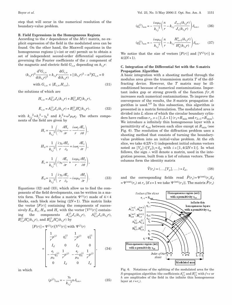
racting device. However, the T matrix may be ill-onditioned because of numerical contaminations. Impor-ant index gap or strong growth of the function f�r ,��ncreases such numerical contaminations. To improve theonvergence of the results, the S-matrix propagation al-orithm is used.4,9 In this subsection, this algorithm isresented in a matrix formulation. The modulated area isivided into L slices of which the circular boundary cylin-ers have radius rs, s� �1,L+1� (r1=Rmin and rL+1=Rmax).e introduce a infinitely thin homogeneous layer with a
ermittivity of �ext between each slice except at Rmin (seeig. 6). The resolution of the diffraction problem uses ahooting method that consists of turning the boundary-alue problem into an initial-value problem. At the sthlice, we take 4�2N+1� independent initial column vectorsoted as �Vp� : ��Vp��i=�pi with i� �1,4�2N+1��. In whatollows, the sign ٠will denote a matrix, used in the inte-ration process, built from a list of column vectors. Theseolumns form the identity matrix
V�rs� = �. . .,�Vp�, . . . � = Id, �38�
nd the corresponding fields read F�rs�=��ext��rs�Id
��ext��rs� at rs [if s=1 we take ��int��r1�]. The matrix F�rs�
ig. 6. Notations of the splitting of the modulated area for the-propagation algorithm (the coefficients Af,n
�s� and Bf,n�s� with f=e or
are amplitudes of the field in the infinite thin homogeneousayer at r=rs).
c+t(rm�kattrr
u
TTfia
Tttr
"
HB=c
kwlwcfa
AwwpfiR(d
�Ingt
5PATF
t
1152 J. Opt. Soc. Am. A/Vol. 23, No. 5 /May 2006 Boyer et al.
ontains the column vectors ��F�rs���i with i� �1,4�2N1��, used as initial values of the field, and we integrate
he differential set of Eq. (26) using a suitable algorithmcombining Runge–Kutta and Adams–Moulton algo-ithms). Compared with Ref. 3, the notations of the ��j�
atrix are changed [see Eqs. (31) and (42) in Ref. 3]: The�j� matrices are normalized by the Bessel and the Han-el functions so as to inject well-conditioned matrices asn initial value in the integration process. This new nota-ion induces that the vector �V�j�� contains the Bessel andhe Hankel functions. At the end of the integration, theesult is a matrix noted as Finteg�rs+1� giving the field ats+1, from which we derived from Eq. (34) the matrix
V�rs+1� = ���ext��rs+1��−1Finteg�rs+1�;
sing Eq. (38), we obtain
V�rs+1� = ���ext��rs+1��−1Finteg�rs+1�V�rs�.
his last equation shows that the transmission matrix�s� that links the coefficients of the developments of theeld at rs to the coefficients of the development of the fieldt rs+1 is given by
T�s� = ���ext��rs+1��−1Finteg�rs+1�. �39�
he integration through each slice provides a T�s� matrixhat links the field at rs+1 to the field at rs. From this ma-rix, we deduce a S�s� matrix that links the fields at rs and1, defined by
s � �1,L + 1�, �]
Be,n�s� Hn
+�kt,extrs�
]
Bh,n�s� Hn
+�kt,extrs�
]
Ae,n�1�Jn�kt,intr1�
]
Ah,n�1� Jn�kt,intr1�
]
�=�S11
�s� S12�s�
S21�s� S22
�s���]
Be,n�1�Hn
+�kt,intr1�
]
Bh,n�1� Hn
+�kt,intr1�
]
Ae,n�s� Jn�kt,extrs�
]
Ah,n�s� Jn�kt,extrs�
]
� . �40�
ere the index �s� of the amplitudes Ae,n�s� , Ah,n
�s� , Be,n�s� , and
h,n�s� can be replaced by (int) when s=1 and (ext) when sL+1. For the particular case of s=1, the S�s� matrix be-omes the identical matrix and k becomes equal to
t,ext
t,int. We have checked that all blocks of this matrix areell conditioned (see also Ref. 4). Briefly, the T�s� matrix
inks the fields at layer �s� and the fields at layer �s+1�hile the S�s� matrix links the scattered fields and the in-
ident fields. The S�s� matrix blocks of the �s+1�th inter-ace are expressed according to those of the sth interfacend to the T�s� matrix blocks Tmn
�s� of the sth slice:
S22�s+1� = S22
�s��T11�s� + T12
�s�S12�s��−1,
S12�s+1� = �T21
�s� + T22�s�S12
�s���T11�s� + T12
�s�S12�s��−1,
S21�s+1� = S21
�s� − S22�s+1�T12
�s�S11�s�,
S11�s+1� = T22
�s�S11�s� − S12
�s+1�T12�s�S11
�s�. �41�
t the end of the integration across the modulated area,e obtain the S matrix of the whole scattering device,hich depends only on the surface �S� and on the opticalarameters of the media. This matrix links the diffractedeld at Rmax and Rmin to the incident field at Rmax andmin. In fact, expressing the exponential function in Eq.
1) in terms of Bessel functions,10 the incident field can beefined in the form
Hz�inc� = exp�i�0z�
n−�
+�
Ah,z exp�− in�inc�inJn�kt,extr�exp�in��
Ez�inc� = exp�i�0z�
n−�
+�
Ae,z exp�− in�inc�inJn�kt,extr�exp�in���.�42�
nside the internal region containing the origin of coordi-ates, we must state Be,n
�int�=Bh,n�int�=0 "n to avoid a diver-
ence of the field �Hn+�0�→�"n�. This condition allows us
o derive through Eq. (40)
�]
Ae,n�int�
]
Ah,n�int�
]
� = S22�]
Ae,zin exp�− in�inc�
]
Ah,zin exp�− in�inc�
]
� ,
�]
Be,n�ext�
]
Bh,n�ext�
]
� = S12�]
Ae,zin exp�− in�inc�
]
Ah,zin exp�− in�inc�
]
� . �43�
. NUMERICAL APPLICATION ONARTICULAR CASES. First Validation Studyhe present theory has been implemented using theORTRAN programming language. It is worth noticing thathe results of the TM and TE polarization studied
pcmgRmttltndi
wstrtg
Wv+uhpttomps
vsdttenso
wd
Twtst�Y
Fo=n
Fwm
Fa=
Boyer et al. Vol. 23, No. 5 /May 2006/J. Opt. Soc. Am. A 1153
reviously5 are associated with the particular case ofonical diffraction with �0=0. In this case, the current nu-erical implementation written for conical diffraction
ives the same results as the ones computed previously inef. 5. To validate and illustrate in more detail the FFFethod applied to cylindrical coordinates, we first study
he simple case of one circular cylinder centered outsidehe origin with a radius R and the center with �R0 ,�0� po-ar coordinates (see Fig. 7). The r coordinate defined onhe circle and related to the maximal angle �m defined isoted as rm=�R0
2−R2. On the � range where the circle isefined in the cross section ���0−�m ,�0+�m��, the diffract-ng surface directrix equation is given by
r��� = R0 cos��� ± �R2 − R02 sin2���,
��r� = cos−1 r2 + r02 − R2
2r0r � , �44�
here the � sign is related to r� �R0−R ,rm� and the �ign is related to r� �rm ,R0+R�. In the modulated area,he permittivity is described by a step function ��r ,�� withespect to �; thus obtaining its Fourier development andhe Toeplitz matrix ��� remains easy. The N���� function isiven by
N���� =r0
Rsin�� − �0�. �45�
e mention that the r component of the surface’s normalector is deduced by Nr= ±�1−N�
2. Outside ��0−�m ,�0�m� we could state that the N�
2 function is extended tonity. In this case, the N�
2, Nr2, and NrN� functions would
ave the advantages of the continuity and of the r inde-endency. Since these functions would be r independent,heir Toeplitz matrices would be calculated once beforehe integration process. However, it is interesting to pointut that, along a circle with radius r included in theodulated area, the N�
2�r ,�� is defined only by one or twooints with the same �N�
2� value. Then we have chosen atraight extension of a N 2�r ,�� function with a constant
ig. 7. Cross section of a circular cylinder centered outside therigin and filled with isotropic and homogeneous media with R1 m, R0=2 m, �0=0°, nint=1.6+0.2i, and next=1, andotations.
�
alue of N�2 evaluated at ��r�. The main advantage of
uch an extension is the simplicity of the calculation of itsevelopments: �N�
2�0=N�2���r�� and �N�
2�n=0, "n�0. Onhe other hand, the NrN��r ,�� function becomes discon-inuous, which leaves the determination of its Fourier co-fficients easy but increases the Gibbs phenomena. Theumerical results show that the two extensions lead toimilar convergence when the order of the Fourier devel-pments is increased.
The differential cross section (DCS) that is determinedith the asymptotic form of the Hankel functions of theiffracted field for r→� is given by
���� = 2�k0
2
kt,ext2��� 2
�kt,ext
n=−�
+�
�− i�nBe,n�ext�ein��2
+0
�ext�� 2
�kt,ext
n=−�
+�
�− i�nBh,n�ext�ein��2� . �46�
o validate our theory and its numerical implementation,e compare the FFF method results with the ones ob-
ained with the MM.1,3 We study the scattering by aingle cylinder (see Fig. 7) and compute the DCS with thewo methods. Figure 8 shows the results of the DCS for0=1 m and �0=0.5 m with a logarithmic scale for the
axis; as can be seen, the FFF method results agree
ig. 8. DCS (�=0° to 180°) for the circular cylinder in Fig. 7ith �inc=0°, �=30°, =0°, and N=50; comparison of the FFFethod and MM for �0=1 m and �0=0.5 m.
ig. 9. Cross section of two identical circular cylinders on the Xxis centered outside the origin with d=1 m, �=1.5 m, nint1.4, and n =1.
ext
fosac
BFIesmqvcsgmmtipf
q=igtfsttbo2fmMatsFtuFnaI
Fd=a
Fcme(v
FcFd(v
Fmete
1154 J. Opt. Soc. Am. A/Vol. 23, No. 5 /May 2006 Boyer et al.
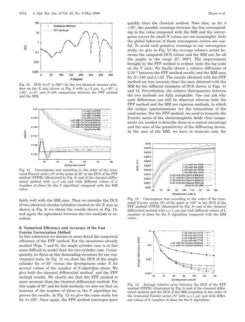
airly well with the MM ones. Then we consider the DCSf two identical circular cylinders located on the X axis ashown in Fig. 9; we obtain the results shown in Fig. 10,nd again the agreement between the two methods is ex-ellent.
. Numerical Efficiency and Accuracy of the Fastourier Factorization Methodn this subsection we discuss in more detail the numericalfficiency of the FFF method. For the structures alreadytudied (Figs. 7 and 9), the single-cylinder case is in factore difficult to model than the two-cylinder case. Conse-
uently, we focus on this demanding structure for our con-ergence tests. In Fig. 11 we show the DCS of the singleylinder for �=30° versus the development order N foreveral values of the number of S-algorithm slices. Weive both the classical differential method7 and the FFFethod results. We clearly see that the FFF method isore accurate than the classical differential method. For
his angle of 30° and for both methods, we also see that anncrease of the number of slices in the S algorithm im-roves the results. In Fig. 12 we give the same study butor �=150°. Once again, the FFF method converges more
ig. 10. DCS (�=0° to 360°) for the two identical circular cylin-ers on the X axis shown in Fig. 9 with �0=2 m, �inc=45°, �30°, =0°, and N=60; comparison between the FFF methodnd the MM.
ig. 11. Convergence test according to the order of the trun-ated Fourier series �N� of the point at 30° in the DCS of the FFFethod (FFFM) (illustrated by Fig. 8) and of the classical differ-
ntial method with �0=1 m and with different values of Lnumber of slices for the S algorithm) compared with the MMalue.
uickly than the classical method. Note that, as for �30°, the possible crossings between the line correspond-
ng to the value computed with the MM and the conver-ence curves for small N values are not meaningful. Onlyhe global behavior of these convergence curves are use-ul. To avoid such putative crossings in our convergencetudy, we give in Fig. 13 the average relative errors be-ween the computed DCS values and the MM one for allhe angles in the range [0°, 360°]. The improvementrought by the FFF method is evident (note the log scalen the Y axis). We finally obtain a relative difference of.10−4 between the FFF method results and the MM onesor N=140 and L=55. The results obtained with the FFFethod are less accurate than the ones obtained with theM for the different examples of DCS shown in Figs. 11
nd 12. Nevertheless, the relative discrepancies betweenhe two methods are fully acceptable. One can ask whyuch differences can still be observed whereas both theFF method and the MM are rigorous methods, in which
he unique approximations are the truncations of thesed series. For the FFF method, we need to truncate theourier series of the electromagnetic fields (four compo-ents are needed to describe them in a conical mounting)nd the ones of the permittivity of the diffracting device.n the case of the MM, we have to truncate only the
ig. 12. Convergence test according to the order of the trun-ated Fourier series �N� of the point at 150° in the DCS of theFF method (FFFM) (illustrated by Fig. 8) and of the classicalifferential method with �0=1 m and with different values of Lnumber of slices for the S algorithm) compared with the MMalue.
ig. 13. Average relative error between the DCS of the FFFethod (FFFM) (illustrated by Fig. 8) and of the classical differ-
ntial method and the DCS of the MM according to the order ofhe truncated Fourier series �N� with �0=1 m and with differ-nt values of L (number of slices for the S algorithm).
FanrelaOs(ltnwttB
fcmIwwgcitplesse
cwncstt
CAwttsn�
s(ectffrN
TriEtwicsNgmite
wmpcfa(icpetawod
DMTuor�(
Boyer et al. Vol. 23, No. 5 /May 2006/J. Opt. Soc. Am. A 1155
ourier–Bessel series of two field components (Ez and Hzre needed in conical mounting) since any series areeeded of the permittivity. There are at least two othereasons explaining the better accuracy of the MM for thexamples shown here. First, for homogeneous and circu-ar inclusions, the reflection matrix relating the incidentnd the scattered field in the MM are known analytically.n the contrary, in the framework of the FFF, the inclu-
ions are described through the permittivity tensor ��more precisely by its Fourier components) in the modu-ated area. Second, there is a crucial difference betweenhe two methods: for the MM no numerical integration isecessary, while resolution such as the one associatedith Eq. (26) of the FFF method requires such an integra-
ion; only analytical changes of basis using Graf ’sheorem2,10 are used for the rewriting of the Fourier–essel series, which lead to an explicit linear problem.All these reasons also explain why the MM is much
aster than the FFF method for the homogeneous and cir-ular examples treated in this study, even if all the nu-erical computations can still be achieved on a single PC.
t is worth considering how the MM accuracy evolveshen noncircular inclusions are considered, and hencehen a numerical integration is required. The resultsiven in Ref. 11 concerning homogeneous and elliptical in-lusions can give us a first evaluation since a numericalntegration is required to compute the reflection matrix ofhe ellipses. The final results obtained by the MM lose ap-roximately three significant digits when these noncircu-ar inclusions are studied. We do not observe such wors-ning of the accuracy within the FFF method whenimilar ellipses are considered instead of circular inclu-ions since the circles are not treated differently than thellipses.
To conclude this subsection, we remind the reader thatircular and homogeneous inclusions are a special case inhich the Multipole Method is certainly the best possibleumerical method since several steps are done analyti-ally. The purpose of the FFF method is not to study suchimple, but more complicated structures; a trade-off is ob-ained between the accuracy speed and the generality ofhe studied structures.
. Devices with Subperiodicity According to �s with MOFs, any device may present a cross sectionith a subperiodicity according to �. This property can be
aken into account in the integration process to reducehe computation time. Let us assume that the device pre-ents a subperiod T such that NTT=2� where NT is theumber of periodicity. Thus the spectra of the functions�r ,�� and N�
2�r ,�� are wider than those obtained withoutubperiodicity. More precisely, we consider a function f����, N�
2 or NrN�) subperiodic with period T. The Fourier co-fficients of f on the 2� range fn �"n�N� and the Fourieroefficients of f on the T range fn� �"n�N� are linked byhe following relations: if n=kNT �"k�N�, then fn= fk� and
n=0 otherwise. Consequently, the Toeplitz matrix of theunction f is made of nonnull diagonals regularly sepa-ated by NT−1 null diagonals. For instance, if N=4 and
=3, the Toeplitz matrix of the function f is
T
�f� =�f0� 0 0 f1� 0 0 f2� 0 0
0 f0� 0 0 f1� 0 0 f2� 0
0 0 f0� 0 0 f1� 0 0 f2�
f−1� 0 0 f0� 0 0 f1� 0 0
0 f−1� 0 0 f0� 0 0 f1� 0
0 0 f−1� 0 0 f0� 0 0 f1�
f−2� 0 0 f−1� 0 0 f0� 0 0
0 f−2� 0 0 f−1� 0 0 f0� 0
0 0 f−2� 0 0 f−1� 0 0 f0�
� . �47�
We notice that the matrix �f� is block diagonalizable.his matrix structure is preserved when such a matrix iseversed or when two such matrices are multiplied; thats why every block of the integration matrix M�r� given byq. (26) has this matrix structure. Finally, we conclude
hat Eq. (26) is split into NT independent differential setsith matrix sizes equal to 4�2N+1� /NT or less. Since the
ntegration computation time depends roughly on theube of the matrix integration size, the time of a succes-ive integration of each differential subset scales asT�4�2N+1� /NT�3= �4�2N+1��3 /NT
2, while the time of thelobal differential set [Eq. (26)] scales as �4�2N+1��3. Iteans that taking into account the subperiodicity accord-
ng to � of the diffracting surface permits us to gain a fac-or of NT
2 on the computation time. Moreover, each differ-ntial subset depends on the reduced Toeplitz matrix:
�f� = � f0� f1� f2�
f−1� f0� f1�
f−2� f−1� f0�� ,
hich simplifies the calculation of the Fourier develop-ents of �, N�
2, and NrN� functions defined only on the Teriod. The subperiodicity according to � was first suc-essfully implemented on an elliptical cross-section sur-ace centered to the origin since it is � periodic �NT=2�nd then on the circular cylinder defined on a period Tdata not shown). We note that this study on subperiodic-ty can be linked to the seminal work of McIsaac12 con-erning waveguide symmetry properties and with the pa-er written by Bai and Li.13 The authors of Ref. 13 havexplicitly shown how the use of group theory permits oneo fairly reduce the computation time on crossed gratingnalysis. More recently, Fini14 has revisited McIsaac’sork to improve the efficiency of several numerical meth-ds if rotational symmetry properties are present in theevice.
. Excitation of the Fundamental Leaky Mode of aicrostructured Optical Fiberhe subperiodicity of the diffracting device is particularlyseful in the case of MOFs. These fibers are usually madef several rings of circular cylinders (filled with vacuum)egularly distributed according to the angular coordinatein a infinite matrix. We thus consider a solid core MOF
Fig. 14) composed of six identical circular cylinders with
a(rsgc=baemcctt(tdfirmsaoMett
fiwkwrmDCcbrrbFw
lslw
Fl
Ffa
FtM�=
FtM�
1156 J. Opt. Soc. Am. A/Vol. 23, No. 5 /May 2006 Boyer et al.
diameter d=1 m and the same distance to the originpitch) R0=�=2.3 m ��0=0° �; it means that the subpe-iod is 2� /6 �NT=6�. In addition, the whole structure hasymmetry planes, so in the formulation used in wave-uide theory,12 this fiber follows the C6v symmetries. Theylinder index is nint=1 and the matrix index is next1.44390356. In our notation [Eq. (3)], the parameter �0ecomes the studied propagation constant usually noteds �. The effective index is defined by neff=� /k0. The well-stablished MM1–3 can also be formulated as a modalethod, and consequently it can find the modes of MOFs
omposed with arbitrary inclusions contained in disjoinedircular cylinders. It gives a complex effective index equalo neff=1.420784+ i7.20952�10−4 with �0=1.56 m forhe fundamental mode, i.e., this mode is a leaky modeeven if the optical indices of the inclusions and the ma-rix are purely real). In addition, we know that the fun-amental mode is twice degenerated.1,12 Its componentelds Ez belong either to the C4 symmetry class [symmet-ic according to the Y axis, u��−��=u���, and antisym-etric according to the X axis, u�−��=−u���] or to the C3
ymmetry class (antisymmetric according to the Y axisnd symmetric according to the X axis). This classificationf symmetry is more precisely explained in the work ofcIsaac.12 We search now to apply these symmetry prop-
rties on the diffracting problem. The mode that belongso the C3 symmetry class is excited when �inc=90° andhe second one (C4 symmetry class) when �inc=0°.
In the framework of our diffraction method, we haverst tried to excite the fundamental mode described aboveith suitable incident wave parameters [Eq. (1)]. Wenow that the real parameter �0 is equal to −kext sin��� inhich kext=k0next; hence we have searched the angle pa-
ameter � such that �0=k0 Re�neff�, and we have approxi-ately found �=−79.73° about ��=−arcsin�Re�neff� /next��.oing so, we have neglected the imaginary part of neff.onsequently, the fundamental mode is only partially ex-ited. Figure 15 shows the computation time versus N foroth the six circular cylinder MOFs defined on the 2� pe-iod and for the one defined on the T=2� /6 period. Theseesults clearly illustrate the improvement brought abouty the subperiodicity concerning the computation time.igure 16 illustrates the normalized �Ez� map associatedith the partial excitations of the fundamental mode be-
ig. 14. Cross section of a MOF composed of six identical circu-ar cylinders with d=1 m, �=2.3 m, nint=1, and next=1.4439.
onging to the C3 symmetry class and Fig. 17 to the C4ymmetric class (N=60 and =0°). The fields seem wellocated around the circular cylinders and the similarityith the MM1 field maps is already clear even if the result
ig. 15. Computation time for the six circular cylinders as aunction of the order of the truncated Fourier series �N�, withnd without taking advantage of the symmetry.
ig. 16. Normalized �Ez� field map obtained thanks to the par-ial excitation (see Fig. 18 for the complete excitation) of theOF fundamental mode belonging to the C3 symmetry class [
inc=90°, =0°, �0=1.56 m, N=60, and �0=k0 Re�neff�1.420784]. The studied fiber is the same as in Fig. 14.
ig. 17. Normalized �Ez� field map obtained thanks to the par-ial excitation (see Fig. 19 for the complete excitation) of theOF fundamental mode belonging to the C4 symmetry class
� =0° �. The studied fiber is the same as in Fig. 14.
inc
st
dobttac
StCcIsrrcesi
6TffnTccistpitpdfisiicbtritsom
Fpf=+ i7.20952�10 ). The studied fiber is the same as in Fig. 14.
Fpfodamental mode. The studied fiber is the same as in Fig. 14.
Fmw
Boyer et al. Vol. 23, No. 5 /May 2006/J. Opt. Soc. Am. A 1157
hown in Fig. 16 is a diffraction phenomenon and not arue mode.
To excite completely the fundamental mode by a inci-ent wave, we now take into account the imaginary partf neff. The complex number �0=k0neff implies that � alsoecomes a complex number. However, this implies that allhe components of the incident fields are proportional tohe same complex number cos���. In this case, the fieldmplitudes Ae,z and Ah,z deduced from Eq. (2) also becomeomplex numbers proportional to cos���:
Ae,z = cos���cos���E�inc��, �48�
Ah,z =1
Zcos���sin���E�inc��. �49�
ince all the other incident field components are propor-ional to Ae,z and Ah,z, they are also proportional to cos���.onsequently, it is not even necessary to determine theos��� factor if we are only interested in normalized fields.n our example, we choose �0=k0neff. Figures 18 and 19how the normalized �Ez� maps associated with the accu-ate excitation of the C3 (and C4) symmetry class mode,espectively. Figure 20 illustrates the modulus of the zomponent of the Poynting vector noted as Sz for bothlectromagnetic field maps �N=60�. We recognize theame field maps as the ones obtained with the MM usedn its mode-searching operation.1
. CONCLUSIONhe described FFF method introduces Toeplitz matrices
or permittivity ��� and �1/�� and also Toeplitz matricesor geometric quantities such as the normal vector compo-ents of the diffracting surface: �N�
2�, �Nr2�, and �N�Nr�.
he convergence results depend directly on these matrixonditions. The numerical implementation on the circlease in which the ��r ,�� and N�
2�r ,�� functions presentmportant variations according to � shows satisfying re-ults for N=50. Moreover, the integration of the differen-ial set in the modulated area fairly simplifies when theossible subperiodicity of the diffracting device is takennto account. We apply the FFF method to simple struc-ures made of circular inclusions so as to be able to com-are it with a known method. However, the FFF methodescribed here in cylindrical coordinates can compute theelds diffracted by more complex structures than the oneshown in this present work: Some other different diffract-ng surfaces have been successfully studied (elliptical cyl-nder, rectangular cylinder, etc.), and the most generalase of anisotropic and/or inhomogeneous media can alsoe analyzed. An association between the FFF method inhe homogeneous and isotropic case and the MM has al-eady been used to study a MOF with ellipticalnclusions.11 Our future work will deal with the adapta-ion of the FFF method applied to light diffraction to theearch of modes into arbitrary cross-section MOFs tovercome the known limitations of the MM1 (inclusionsust be inscribed in nonoverlapping circles, the matrix
ig. 18. Normalized �Ez� field map obtained thanks to the com-lete excitation (see Fig. 16 for the partial excitation) of the MOFundamental mode belonging to the C3 symmetry class (�inc90°, =0°, �0=1.56 m, N=60, and �0=k0neff=1.420784
−4
ig. 19. Normalized �Ez� field map obtained thanks to the com-lete excitation (see Fig. 17 for the partial excitation) of the MOFundamental mode belonging to the C4 symmetry class (�inc=0°;ther parameters are identical to the ones of Fig. 18) of the fun-
ig. 20. Normalized �Sz� field map computed from the electro-agnetic fields associated with Fig. 18 (the result is similarhen the results associated with Fig. 19 are considered).
pfa
ATPksd
1
1
1
1
1
1158 J. Opt. Soc. Am. A/Vol. 23, No. 5 /May 2006 Boyer et al.
ermittivity must be homogeneous). In this case, the dif-raction problem becomes an homogeneous problem, i.e.,n eigenvalue problem.
CKNOWLEDGMENTShe support of the European Community-funded projectHOREMOST (FP6/2003/IST/2-511616) is gratefully ac-nowledged. The content of this work is the sole respon-ibility of the authors. We thank the Free Software Foun-ation and the Scilab Consortium for their help.
REFERENCES1. F. Zolla, G. Renversez, A. Nicolet, B. Kuhlmey, S.
Guenneau, and D. Felbacq, Foundations of PhotonicCrystal Fibers (Imperial College Press, 2005).
2. T. P. White, B. T. Kuhlmey, R. C. McPhedran, D. Maystre,G. Renversez, C. M. de Sterke, and L. C. Botten, “Multiplemethod for microstructured optical fibers. I. Formulation,”J. Opt. Soc. Am. B 19, 2322–2330 (2002).
3. B. T. Kuhlmey, T. P. White, G. Renversez, D. Maystre, L. C.Botten, C. M. de Sterke, and R. C. McPhedran, “Multipolemethod for microstructured optical fibers. II.Implementation and results,” J. Opt. Soc. Am. B 19,2331–2340 (2002).
4. M. Nevière and E. Popov, Light Propagation in PeriodicMedia: Differential Theory and Design (Marcel Dekker,2003).
5. P. Boyer, E. Popov, M. Nevière, and G. Tayeb, “Diffractingtheory in TM polarization: application of the fast Fourierfactorization method to cylindrical devices with arbitrarycross section,” J. Opt. Soc. Am. A 21, 2146–2153 (2004).
6. M. Nevière, “The homogeneous problem,” inElectromagnetic Theory of Gratings, R. Petit ed. (Springer-Verlag, 1980).
7. P. Vincent and R. Petit, “Sur la diffraction d’une onde planepar un cylindre diélectrique,” Opt. Commun. 5, 261–266(1972).
8. L. Li, “Use of Fourier series in the analysis ofdiscontinuous periodic structures,” J. Opt. Soc. Am. A 13,1870–1876 (1996).
9. L. Li, “Formulation and comparison of two recursive matrixalgorithms for modeling layered diffraction gratings,” J.Opt. Soc. Am. A 13, 1024–1035 (1996).
0. M. Abramowitz and L. E. Stegun, eds., Handbook ofMathematical Functions with Formulas, Graphs, andMathematical Tables (National Bureau of Standards,1972).
1. S. Campbell, R. C. McPhedran, C. M. de Sterke, and L. C.Botten, “Differential multipole method for microstructuredoptical fibers,” J. Opt. Soc. Am. B 21, 1919–1928 (2004).
2. P. R. McIsaac, “Symmetry-induced modal characteristics ofuniform waveguides. I. Summary of results,” IEEE Trans.Microwave Theory Tech. MTT-23, 421–429 (1975).
3. B. Bai and L. Li, “Reduction of computation time forcrossed-grating problems: a group-theoretic approach,” J.Opt. Soc. Am. A 21, 1886–1894 (2004).
4. J. M. Fini, “Improved symmetry analysis of many-modedmicrostructure optical fibers,” J. Opt. Soc. Am. B 21,1431–1436 (2004).