Special RatingsCCC — — — — — — — — — — — — — — — —Fed. SpecsW-C-375B/GEN X — — — X — — — — X — X X — X X
Other Standard HACR [7]NOM HACR [7] — — — HACR
[7] — HACR [7] HACR [7]
Accessories and ModificationsShunt Trip [8] X X X X X X X X X [9] X X X — — — —Undervoltage Trip — — — — — — — — — — — — — — — —Auxiliary Switches [8] X X X X X X X X X [9] X X X — X — —Alarm Switch [8] X X X X X X X X X [9] X X X — X — —Handle Operators — — — — — — — — — — — — — — — —Handle PadlockAttachment X X X X X X X X X X X X X X X X
Trip System TypeThermal-magnetic X X X X X X X X X X X X X X X XMolded Case Switch X X X — — — — — — — — — — — — —Dimensions (1P Unit Mount)Dimensions(1P UnitMount)in. (mm)
[1] For dimensions for QOB2150VH, QOB3110VH, QOB3125VH and QOB3150VH, see page 7-83[2] 2P 150–200 A requires 4P width.[3] See the Supplemental Digest, Section 3 for 3Ø corner grounded systems.[4] 22 kA @ 240 Vac for 3P only.[5] 1P and 2P, 10–70 A and 3P 10–60 A only.[6] See the Supplemental Digest Section 10 for circuit breakers with IEC ratings.[7] HACR on QO, QOB 1P 10–70 A, 2P 15–100 A, 3P 10–100 A; QOB-VH 1P 15–70 A, 2P 15–125 A, 3P 15–100 A.[8] Factory-installed option only.[9] Factory-installed accessories are not available on QOB-VH 2P150 A and 3P 110–150 A.
Special RatingsCCC — — — — — — — X [14] X [14] X [14] — — —Fed. Specs W-C-375B/GEN X — — X — X X X X X XOther Standard NOM — NOM HACR [15] — — —Accessories and ModificationsShunt Trip — — — — — — — X [16] X [16] X [16] X [16] — X [16]Undervoltage Trip — — — — — — — — — — — — —Auxiliary Switches X X X X X X X X [16] X [16] X [16] X[16] — —Alarm Switch X X X X X X X X [16] X [16] X [16] X [16] — —Handle Operators — — — — — — — — — — — — —Handle Padlock Attachment X X X X X X X X X X X X XTrip System TypeThermal-magnetic X X X X X X X X X X X X XMolded Case Switch — — — — — — — — X X — — —Dimensions (1P Unit Mount)
NOTE: All circuit breakers on this chart are UL Listed and CSA Certified unless otherwise noted.
7MINIATUREANDMOLDEDCASE
CIRCUIT
BREAKERS
[10] QYU is a UL 1077 supplementary protector.[11] For information regarding 3Ø corner grounded systems see the Supplemental Digest, Section 3.[12] 1P and 2P, 10–70 A and 3P 10–60 A only.[13] QOU is UL Listed for 60 Vdc per pole 80–100 A, 1P; 80–125 A, 2P; and 70–100 A, 3P.[14] 15–70 A 1P and 2P, 15–60 A 3P[15] HACR on QOU 1P and 3P 15–100 A, 2P 15–125 A;[16] Factory-installed option only.[17] QOM1 and QOM2 dimensions are for 2-pole unit.
Special RatingsCCC — — — — — — — — —Fed. SpecsW-C-375B/GEN X X X X X X X X X
Other Standard HACR [22] NOM HACR [22]Accessories and ModificationsShunt Trip [23] — — — — — — — — —Undervoltage Trip — — — — — — — — —Auxiliary Switches [23] — — — — — — — — —Alarm Switch [23] — — — — — — — — —Handle Operators — — — — — — — — —Handle PadlockAttachment X X X X — — — — X [24]
Trip System TypeThermal-magnetic X X X X X X X X XMolded Case Switch — — — — — — — — —Dimensions (1P Unit Mount)
Dimensions(1P Unit Mount)in. (mm)
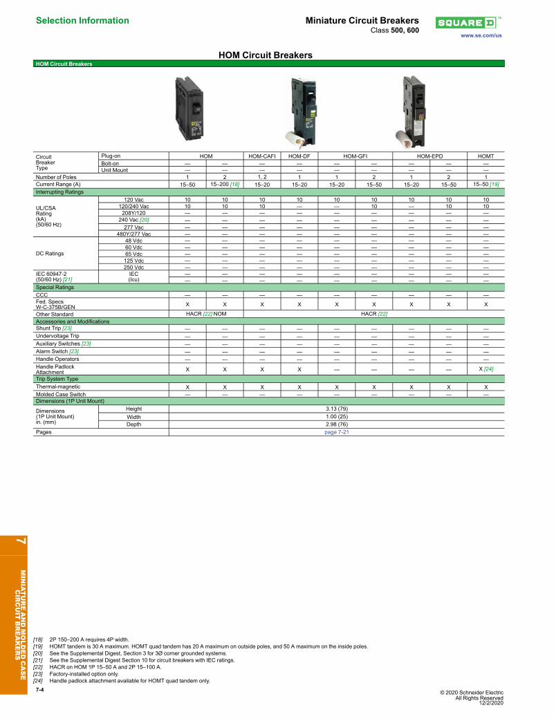
Height 3.13 (79)Width 1.00 (25)Depth 2.98 (76)
Pages page 7-21
7MINIATUREANDMOLDEDCASE
CIRCUIT
BREAKERS
[18] 2P 150–200 A requires 4P width.[19] HOMT tandem is 30 A maximum. HOMT quad tandem has 20 A maximum on outside poles, and 50 A maximum on the inside poles.[20] See the Supplemental Digest, Section 3 for 3Ø corner grounded systems.[21] See the Supplemental Digest Section 10 for circuit breakers with IEC ratings.[22] HACR on HOM 1P 15–50 A and 2P 15–100 A.[23] Factory-installed option only.[24] Handle padlock attachment available for HOMT quad tandem only.
Special RatingsCCC X X X X X X X X — — — — — —Fed. Specs W-C-375B/GEN X X X — — — — — X X X X X XOther Standard IEC HACRAccessories and ModificationsShunt Trip X X X X X X X X X [33] X [33] X [33] X [33] X [33] X [33]Undervoltage Trip X X X X X X X X — — — — — —Auxiliary Switches X X X X X X X X X [33] X [33] X [33] X [33] X [33] X [33]Alarm Switch X X X X X X X X X [33] X [33] X [33] X [33] X [33] X [33]Handle Operators X X X X X X X X — — — — — —Handle Padlock Attachment X X X X X X X X X X X X X XTrip System TypeThermal-magnetic X X X X X X X X X X X X X XMolded Case Switch — — — — — — — — — — — — — —Dimensions (1P Unit Mount)
NOTE: All circuit breakers on this chart are UL Listed and CSA Certified unless otherwise noted.
7MINIATUREANDMOLDEDCASE
CIRCUIT
BREAKERS
[25] C60 are recognized components per UL 1077.[26] 14 kA up to 35 A, 10 kA from 40 to 63 A.[27] 14 kA up to 32 A, 10 kA from 40 to 63 A.[28] For information regarding 3Ø corner grounded systems see the Supplemental Digest, Section 3.[29] 10 kA up to 32 A, 5 kA from 40 to 63 A.[30] Up to 35 A.[31] 10 kA up to 35 A.[32] 2 poles must be wired in series for 500 Vdc.[33] Factory-installed option only.
Special RatingsCCC X X X X X X X X X X X X X XFed. Specs W-C-375B/GEN X X X X X X X X X X X X X XHACR X X X X X X X X X X X X X XConnections/TerminationsUnit Mount X X X X X X X X X X X X X XI-Line™ X X X X X X X X X X X X X XRear Connection — — — — X [39] X [39] X X X X X X X XDrawout — — — — X [39] X [39] X X X X X X X XOptional Lugs X X X X X [39] X [39] X X X X X X X XAccessories and ModificationsShunt Trip X X X X X X X X X X X X X XUndervoltage Trip X X X X X X X X X X X X X XAuxiliary Switches X X X X X X X X X X X X X XAlarm Switch X X X X X X X X X X X X X XMotor Operator — — — — X [39] X [39] X X X X X X X XHandle Operators X X X X X [39] X [39] X X X X X X X XMechanical Interlocks (3P) X X X — X X X X X X X X X XHandle Padlock Attachment X X X X X [39] X [39] X X X X X X X XCylinder Lock (3P) — — — — — — — — — — — — — —Optional GF Protection — — — — X X X X X X X X X XTrip System TypeThermal-magnetic X X X X X X X X — X X X X XInstantaneous-only (MCP) — — — — — X X [40] X [40] X [40] — X [40] X [40] X XMolded Case Switch(Automatic) X X X X — X — X — — X — X X
Electronic — — — — X [40] X [40] X [40] X [40] X [40] X [40] X [40] X [40] X [40] X [40]Enclosures (page 7-83–page 7-85)General Purpose (NEMA 1) — — — — X X X X — X X X X —Raintight (NEMA 3R) — — — — X X X X — X X X X —Dust-tight (NEMA 12) — — — — X X X X — X X X X —Watertight (NEMA 4, 4X, 5) — — — — X X X X — X X X X —Explosion Proof (NEMA 7, 9) — — — — — — — — — X [41] X [41] — — —Dimensions(3P UnitMount)in. (mm)
NOTE: All circuit breakers on this chart are UL Listed and CSA Certified unless otherwise noted.
7MINIATUREANDMOLDEDCASE
CIRCUIT
BREAKERS
[34] 2P in a 3P module.[35] 70–250 A with electronic trip system[36] Not available with electronic trip units[37] 1PAvailable at 125 Vdc[38] Dual UL and IEC ratings and CE markings on circuit breakers. For additional IEC ratings, see the Supplemental Digest, Section 10.[39] Not available in HD and HG 2P rating (2P module).[40] 3P only.[41] Not UL Listed due to wire bending space.
Special RatingsCCC — — — — — — — X X X X XFed. Specs W-C-375B/GEN X X X X X X X X X X X XHACR (2P, 3P) X X X — — X X X X X X X
Connections/TerminationsUnit Mount X X X X X X X X X X X XI-Line™ X X X X X X X X X X X XRear Connection — — — — X X X X X X X XDrawout — — — — — — — X X X X XOptional Lugs — — — — X X X X X X X X
Accessories and ModificationsShunt Trip — — — — X X X X X X X XUndervoltage Trip — — — — X X X X X X X XAuxiliary Switches — — — — X X X X X X X XAlarm Switch — — — — X X X X X X X XMotor Operator — — — — X X X X X X X XHandle Operators — — — — X X X X X X X XMechanical Interlocks (3P) X X X X — X [47] X [47] X X X X XHandle Padlock Attachment X X X X X X X X X X X XCylinder Lock (3P[48]) — — — — X X X — — — — —Optional GF Protection[49] — — — — — — — X X X X X
Trip System TypeThermal-magnetic X X X X X X X — — — — —Instantaneous-only (MCP) — — — — — X X — X X X XMolded Case Switch(Automatic) X — — — — — X — X — X X
Electronic — — — — — — — X X X X XEnclosures (page 7-83–page 7-85)General Purpose (NEMA 1) X X X X X X X — — — — —Raintight (NEMA 3R) X X X X X X X — — — — —Dust-tight (NEMA 12) — — — — X X X X [50] X [50] X [50] X [50] X [50]Watertight (NEMA 4, 4X, 5) — — — — X X X — — — — —Explosion Proof (NEMA 7, 9) — — — — — — — — — — — —
NOTE: All circuit breakers on this chart are UL Listed and CSA Certified unless otherwise noted.
7MINIATUREANDMOLDEDCASE
CIRCUIT
BREAKERS
[42] I-Line Q-frame circuit breakers are available 70–225 A only. 250 A Q-frame unit-mount circuit breakers are limited to Cu conductors only.[43] Not available with electronic trip units[44] Ungrounded UPS systems only. See page 7-45. Special DC J-Frame only.[45] Dual UL and IEC ratings and CE markings on circuit breakers. For additional IEC ratings, see the Supplemental Digest, Section 10.[46] For additional IEC ratings, see the Supplemental Digest Section 10.[47] Requires circuit breaker with WB suffix .[48] Factory-installed option only.[49] Requires factory-installed “G” shunt trip and 3P module.[50] Enclosure rating 1, 3R, 5 and 12.,
Special RatingsCCC X X X X X X X X X XFed. Specs W-C-375B/GEN X X X X X X X X X XHACR (2P, 3P) X X X X X X X X X X
Connections/TerminationsUnit Mount X X X X X X X X X XI-Line™ X X X X X X X [53] X [53] X [53] X[53]Rear Connection — — — — — — — — — —Drawout — — X [54] X [54] X [54] X [54] — — — —Optional Lugs X X X X X X X X X X
Accessories and ModificationsShunt Trip X X X X X X X X X XUndervoltage Trip X X X X X X X X X XAuxiliary Switches X X X X X X X X X XAlarm Switch X X X X X X X X X XMotor Operator — — X [54] X [54] X [54] X [54] — — — —Handle Operators — — X [54] X [54] X [54] X [54] — — — —Mechanical Interlocks (3P) — — X X X X — — — —Handle Padlock Attachment X X X X X X X X X XCylinder Lock (3P) — — — — — — — — — —Optional GF Protection — — X X X X X X X X
Trip System TypeThermal-magnetic — — — — — — — — — —Instantaneous-only (MCP) — — — X X — — — — —Molded Case Switch (Automatic) — — X X X X X X X XElectronic X X X X X X X X X X
Enclosures (page 7-83–page 7-85)General Purpose (NEMA 1) X X X X X X — — — —Raintight (NEMA 3R) X X X X X X — — — —Dust-tight (NEMA 12) X X X X X X — — — —Watertight (NEMA 4, 4X, 5) X X — — — — — — — —Explosion Proof (NEMA 7, 9) — — — — — — — — — —
NOTE: All circuit breakers on this chart are UL Listed and CSA Certified unless otherwise noted.
7MINIATUREANDMOLDEDCASE
CIRCUIT
BREAKERS
[51] Ungrounded UPS systems only. See page 7-45.[52] Dual UL and IEC ratings and CE markings on circuit breakers. For additional IEC ratings, see the Supplemental Digest, Section 10.[53] 1000 A and 1200 A only.[54] 65/50 kA Icu/Ics for 450–600 A ratings.
Connections/TerminationsUnit Mount X X X X X X X X X X X X XI-Line™ — — — — — — — — — — — — —Rear Connection X X X X X X X X X X X X XDrawout X X X X X X X X X X X X XOptional Lugs — — — — — — — — — — — — —
Accessories and ModificationsShunt Trip X X X X X X X X X X X X XUndervoltage Trip X X X X X X X X X X X X XAuxiliary Switches X X X X X X X X X X X X XAlarm Switch X X X X X X X X X X X X XMotor Operator X X X X X X X X X X X X XHandle Operators — — — — — — — — — — — — —Mechanical Interlocks X X X X X X X X X X X X XPadlock Attachment X X X X X X X X X X X X XOptional GF Protection X X X X X X X X X X X X X
Trip System TypeThermal-magnetic — — — — — — — — — — — — —Instantaneous-only (MCP) — — — — — — — — — — — — —Electronic X X X X X X X X X X X X X
Connections/TerminationsUnit Mount X X X X X X X X X X X X XI-Line™ — — — — — — — — — — — — —Rear Connection X X X X X X X X X X X X XDrawout X X X X X X X X X X X X XOptional Lugs — — — — — — — — — — — — —
Accessories and ModificationsShunt Trip X X X X X X X X X X X X XUndervoltage Trip X X X X X X X X X X X X XAuxiliary Switches X X X X X X X X X X X X XAlarm Switch X X X X X X X X X X X X XMotor Operator X X X X X X X X X X X X XHandle Operators — — — — — — — — — — — — —Mechanical Interlocks X X X X X X X X X X X X XPadlock Attachment X X X X X X X X X X X X XCylinder Lock — — — — — — — — — — — — —Optional GF Protection X X X X X X X X X X X X X
Trip System TypeThermal-magnetic — — — — — — — — — — — — —Instantaneous-only (MCP) — — — — — — — — — — — — —Molded Case Switch(Automatic) X X X X X X X X X X X X X
QO Plug-On Circuit Breakers QO™ and QOU Miniature Circuit BreakersClass 730, 731, 733 / Refer to Catalog: 0730CT9801
QO Standard Plug-On Circuit BreakersSquare D brand QO miniature circuit breakers are plug-on products for use in QO loadcenters, NQOD and NQ panelboards, NQOD and NQ OEM interiors or Speed-D™
switchboard distribution panels. Bolt-on QOB circuit breakers are for use in NQOD andNQ panelboards or interiors. [1]The Square D exclusive Qwik-Open™ mechanism, with a trip reaction within 1/60th of asecond, is standard on all 1P 15 and 20 A QO circuit breakers.
10 k AIR10 A QO110 QO210 — QO31015 A QO115 [4] [5] QO215 [4] QO215H QO315 [4]20 A QO120 [4] [5] QO220 [4] QO220H QO320 [4]25 A QO125 [4] QO225 [4] QO225H QO325 [4]30 A QO130 [4] QO230 [4] QO230H QO330 [4]35 A QO135 [4] QO235 [4] — QO335 [4]40 A QO140 [4] QO240 [4] QO240H QO340 [4]45 A QO145 [4] QO245 [4] — QO345 [4]50 A QO150 [4] QO250 [4] QO250H QO350 [4]60 A QO160 [4] QO260 [4] QO260H QO360 [4]70 A QO170 [4] QO270 [4] QO270H QO370 [4]80 A — QO280 [4] QO280H QO380 [4]90 A — QO290 [4] QO290H QO390 [4]100 A — QO2100 [4] QO2100H QO3100 [4]110 A — QO2110 [4] — —125 A — QO2125 [4] — —150 A — QO2150 [4] [6] [7] — —175 A — QO2175 [4] [6] [7] — —200 A — QO2200 [4] [6] [7] — —
Molded Case Switch 60 A max.–240 Vac — QO200 QO300Molded Case Switch 100 A max.–240 Vac — QO2000 [8] QO3000 [8]22 k AIR [4]
15 A QO115VH [5] QO215VH [9] — QO315VH [9]20 A QO120VH [5] QO220VH [9] — QO320VH [9]25 A QO125VH QO225VH [9] — QO325VH [9]30 A QO130VH QO230VH [9] — QO330VH [9]40 A QO140VH QO240VH [9] — QO340VH [9]50 A QO150VH QO250VH [9] — QO350VH [9]60 A QO160VH QO260VH [9] — QO360VH [9]70 A QO170VH QO270VH [9] — QO370VH [9]80 A — QO280VH [9] — QO380VH [9]90 A — QO290VH [9] — QO390VH [9]100 A — QO2100VH [9] [10] — QO3100VH [9]110 A — QO2110VH [9] [10] — —125 A — QO2125VH [9] [10] — —150 A — QO2150VH [6] [9] [7] — —175 A — QO2175VH [6] [9] [7] — —200 A — QO2200VH [6] [9] [7] — —
42 k AIR [4] 40 A — QOH240 [8] — — 45 A — QOH245 [8] — — 50 A — QOH250 [8] — — 60 A — QOH260 [8] — — 70 A — QOH270 — — 80 A — QOH280 — — 90 A — QOH290 — —100 A — QOH2100 — —110 A — QOH2110 [8] — —125 A — QOH2125 — —
65 k AIR [4] 15 A QH115 [5] [11] QH215[11] — QH315 [4][11] 20 A QH120 [5] QH220 — QH320[11] 25 A QH125 [8] [11] QH225 [8] [11] — QH325 [8] 30 A QH130[11] QH230 — QH330[11]
Refer to page 7-2 for Interrupting Ratings, Accessories, and Dimensions.
7MINIATUREANDMOLDEDCASE
CIRCUIT
BREAKERS
[1] See Digest Section 1 for load centers, and Section 9 for panelboards and interiors.[2] 10–30 A circuit breakers are suitable for use with 60oC or 75oC conductors. 35–125 A circuit breakers are suitable for use with 75oC conductors.[3] UL Listed 5 k AIR on corner grounded Delta systems.[4] UL Listed as HACR type for use with air conditioning, heating and refrigeration equipment haing motor group combinations and marked for use with HACR type circuit breakers.[5] UL Listed as SWD (switching duty) rated. Suitable for switching 120 Vac fluorescent lighting loads.[6] Requires four spaces (1 AWG–300 kcmil Al/Cu.) Suitable for switching 120 Vac fluorescent lighting loads.[7] Not suitable for use in 3Ø panels. Use only in 1Ø panel rated 150 A or greater.[8] Order only. Contact your local Field Office.[9] UL Listed for use ahead of QO, QO-GFI, QO-EPD, QOT, QO-AFI, and QO-PL 10 k AIR circuit breakers to permit their application at 22 kA fault level.[10] 100 A maximum branch mounted opposite.[11] This product is discontinued.
QO™ and QOU Miniature Circuit Breakers QO Plug-On Circuit Breakerswww.se.com/usClass 730, 731, 733 / Refer to Catalog: 0730CT9801
QO/QOB Ring TerminalTable 7.2: QO/QOB Ring Terminal—Factory-Installed Only
Ampere Rating Poles Suffix10–30 A 1, 2, 3 523735–60 A 1,2
523835–50 A 3 70–110 A 2 5273 60–100 A 3
Wire Sizes for QO/QOB Circuit BreakersTable 7.3: Wire Sizes for QO/QOB Circuit Breakers
Circuit Breaker Type Ampere Rating[12]
Wire Size(AWG/kcmil)
QO1P
10–30 A 14–8 Al/Cu10–30 A (2) 14–10 Cu35–70 A 8–2 Al/Cu
QO2P
10–30 A 14–8 Al/Cu10–30 A (2) 14–10 Cu35–70 A 8–2 Al/Cu80–125 A 4–2/0 Al/Cu150–200 A 4–300 Al/Cu
QO3P
10–30 A 14–8 Al/Cu, (2) 14-10 Cu35–70 A 8–2 Al/Cu80–125 A 4–2/0 Al/Cu
QOB-VH 110–150 A 4–300 Al/CuQOT 15–20 A 12–8 Al 14–8 Cu
QO-AFI, QO-GFI or QO-EPD 15–30 A 12–8 Al 14–8 Cu40, 50, 60 A 12–4 Al 14–6 Cu
QO-PL 10–60 A 12–2 Al 14–2 Cu
QOTand QO Tandem Circuit Breakers
QOT 1P Tandem1 Space Required
QOT tandem circuit breakers have a mounting cam as shown. Installation into a QO loadcenter can only be made in those positions having a mounting pan rail slot. MeetsParagraph 408.54 of the NEC®. UL Listed as Class CTL.
Table 7.4: QOT Tandem Circuit Breakers (CTL)—Not Compatible with Plug-onNeutral Systems
Ampere Rating [12] Cat. No. [13]1P—120/240 Vac
15 A and 15 A QOT151515 A and 20 A QOT152020 A and 20 A QOT2020
2P—120/240 Vac Common TripOrder two QOT1515 or QOT2020 circuit breakers and handle tie QOTHT for common switching of center two poles.
Pan Rail Slot
Rail BeadMounting Cam
Table 7.5: QO Tandem Circuit Breakers (non-CTL)—Compatible with Plug-onNeutral Systems
Ampere Rating [12] Cat. No. [13]1P—120/240 Vac—1 Space Required
15 A and 15 A QO151515 A and 20 A QO152020 A and 20 A QO202020 A and 30 A QO203030 A and 20 A QO3020
Two 1P Individual Trip—120/240 Vac—2 Spaces Required15 A and 15 A Order two QO1515 or QO2020 circuit breakers and
handle tie QOTHT15 A and 20 A20 A and 20 A —20 A and 30 A QO20303020 [14]30 A and 20 A —
7MINIATUREANDMOLDEDCASE
CIRCUIT
BREAKERS
[12] 10–30 A circuit breakers are suitable for use with 60oC or 75oC conductors. 35–125 A circuit breakers are suitable for use with 75oC conductors.[13] UL Listed as HACR type for use with air conditioning, heating and refrigeration equipment haing motor group combinations and marked for use with HACR type circuit breakers.[14] Includes two circuit breakers (one QO2030 and one QO3020) and handle tie QOTHT.
QO Plug-On Circuit Breakers QO™ and QOU Miniature Circuit BreakersClass 685, 690, 730, 912, 950 / Refer to Catalog: 0730CT9801
QO Arc-Fault Circuit Breaker (QO-CAFI)
1PQO-CAFI
Plug-On Neutral
1PQO-CAFIPigtail
QO arc-fault circuit breakers provide protection for Series and Parallel Type Arcing asrequired by the NEC and local code adoption, and comply with UL1699.
One–Pole 120 Vac Two–Pole 120/240 Vac10 k AIR1 SpaceRequired
22 k AIR1 Space Required
10 k AIR2 Space Required
22 k AIR2 Space Required
CombinationArc-faultInterrupter(PigtailNeutral)
1520
QO115CAFIQO120CAFI
QO115VHCAFIQO120VHCAFI
QO215CAFI [16]QO220CAFI [16]
QO215VHCAFI [16]QO220VHCAFI [16]
Plug-OnNeutral
CombinationArc-faultInterrupter
1520
QO115PCAFIQO120PCAFI
QO115VHPCAFIQO120VHPCAFI
QO Dual Function Circuit Breaker
1P QO-DFPlug-on Neutral
1P QO-DFPigtail
QO Combination Arc Fault and Ground Fault Circuit Interrupters (Dual Function) provideoverload and short circuit protection, plus arc fault and ground fault protection inaccordance with the NEC, UL1699 and UL943.
Table 7.7: QO-DF Circuit Breakers
Circuit Breaker Type [15] AmpereRating
1P 120 Vac10 k AIR
1 Space Required
1P 120 Vac22 k AIR
1 Space RequiredCombination Arc-fault and Ground Fault
Qwik-Gard™ circuit breakers provide overload and short circuit protection, combined withClass A ground fault protection. Class A denotes a ground fault circuit interrupter that willtrip when a fault current to ground is 6 mA or more, for people protection. Do not connectto more than 250 feet of load conductor for the total one-way run to prevent nuisancetripping.
Table 7.8: QO-GFI Circuit Breakers
CircuitBreakerType
AmpereRating[17]
Qwik-Gard Circuit Breakers With Ground Fault Circuit Interrupter
[15] UL Listed as HACR type for use with air conditioning, heating and refrigeration equipment haing motor group combinations and marked for use with HACR type circuit breakers.[16] For 120/240 V only, not for 208Y/120 V.[17] 10–30 A circuit breakers are suitable for use with 60oC or 75oC conductors. 35–60 A circuit breakers are suitable for use with 75oC conductors.[18] Suitable only for feeding 240 Vac and 208 Vac two-wire loads. Does not contain load neutral connection.[19] New Plug-On Neutral
QO™ and QOU Miniature Circuit Breakers QO Plug-On Circuit Breakerswww.se.com/usClass 685, 690, 730, 912, 950 / Refer to Catalog: 0730CT9801
QO-EPD/EPE Circuit Breakers
QO 1PWith Shunt Trip
QO-EPD/EPE circuit breakers provide overload and short circuit protection combinedwith Class B ground fault protection. They are designed to provide ground faultprotection of equipment at a 30 mA level (EPD) or 100 mA level (EPE). They are notdesigned to protect people from electrical shock.
QO High Intensity Discharge Circuit Breakers (QO-HID)HID circuit breakers are for use on circuits feeding fluorescent and high intensitydischarge (HID) lighting systems such as mercury vapor, metal halide, or high pressuresodium. These circuit breakers are physically interchangeable with QO circuit breakers.
Key operated QO circuit breakers are available in single-pole construction and can bemounted in any single-pole space which will accept a standard QO circuit breaker. Thesecircuit breakers can be turned ON or OFF or to RESETwith a special key (catalognumber QOK10) included with the circuit breaker. These circuit breakers are UL Listedand available as shown in the table.
Table 7.12: QO-K Circuit Breakers120 Vac—10 k AIR (1 Space Required)
QO High Magnetic Trip Circuit Breakers (QO-HM)High magnetic trip circuit breakers are recommended for applications where high initialinrush may occur and for individual dimmer applications.
Table 7.13: QO-HM Circuit Breakers120 Vac—10 k AIR
Ampere Rating [23] 1P15 A QO115HM [26] [24]20 A QO120HM [26] [24]
7MINIATUREANDMOLDEDCASE
CIRCUIT
BREAKERS
[20] 10–30 A circuit breakers are suitable for use with 60oC or 75oC conductors. 35–60 A circuit breakers are suitable for use with 75oC conductors.[21] See note in Instruction Bulletin when using in an enclosure with a QO403 or QON prefix.[22] Suitable only for feeding 240 Vac and 208 Vac two-wire loads. Does not contain load neutral connection.[23] 10–30 A circuit breakers are suitable for use with 60oC or 75oC conductors. 35–60 A circuit breakers are suitable for use with 75oC conductors.[24] UL Listed as SWD (switching duty) rated. Suitable for switching 120 Vac fluorescent lighting loads.[25] This product is discontinued.[26] UL Listed as HACR type for use with air conditioning, heating and refrigeration equipment haing motor group combinations and marked for use with HACR type circuit breakers.
QO Plug-On Circuit Breakers QO™ and QOU Miniature Circuit BreakersClass 685, 690, 730, 912, 950 / Refer to Catalog: 0730CT9801
Non-Automatic (Standard) Miniature SwitchesMiniature non-automatic switches have the same physical packaging as miniature circuitbreakers, but open only when the handle is switched to the OFF position.Non-automatic switches provide no overcurrent protection or short circuit protection.They must not be used on systems that have an available fault current greater than thevalues listed in the table. Non-automatic switches are UL Listed per UL 1087 and areCSA certified.
QO™ and QOU Miniature Circuit Breakers Accessorieswww.se.com/us
Class 1130 / Refer to Catalog 1100CT0501
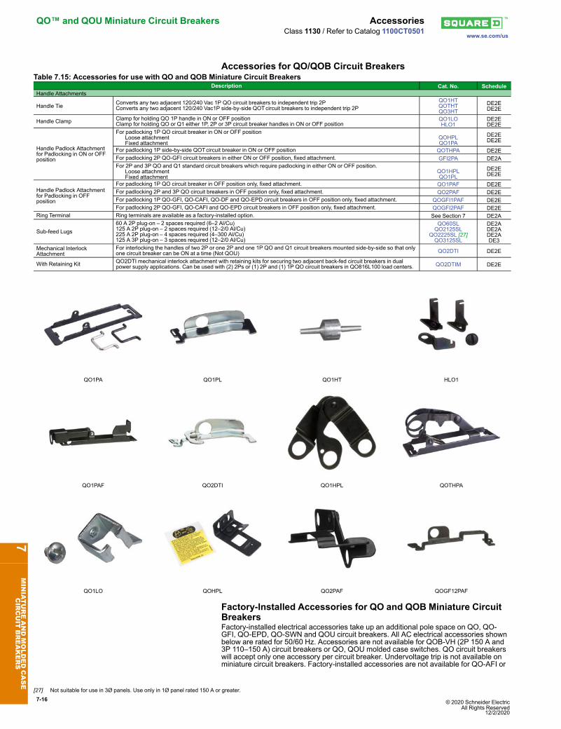
Accessories for QO/QOB Circuit BreakersTable 7.15: Accessories for use with QO and QOB Miniature Circuit Breakers
Description Cat. No. ScheduleHandle Attachments
Handle Tie Converts any two adjacent 120/240 Vac 1P QO circuit breakers to independent trip 2PConverts any two adjacent 120/240 Vac1P side-by-side QOTcircuit breakers to independent trip 2P
QO1HTQOTHTQO3HT
DE2EDE2E
Handle Clamp Clamp for holding QO 1P handle in ON or OFF positionClamp for holding QO or Q1 either 1P, 2P or 3P circuit breaker handles in ON or OFF position
QO1LOHLO1
DE2EDE2E
Handle Padlock Attachmentfor Padlocking in ON or OFFposition
For padlocking 1P QO circuit breaker in ON or OFF position Loose attachment Fixed attachment
QOHPLQO1PA
DE2EDE2E
For padlocking 1P side-by-side QOTcircuit breaker in ON or OFF position QOTHPA DE2EFor padlocking 2P QO-GFI circuit breakers in either ON or OFF position, fixed attachment. GFI2PA DE2AFor 2P and 3P QO and Q1 standard circuit breakers which require padlocking in either ON or OFF position. Loose attachment Fixed attachment
QO1HPLQO1PL
DE2EDE2E
Handle Padlock Attachmentfor Padlocking in OFFposition
For padlocking 1P QO circuit breaker in OFF position only, fixed attachment. QO1PAF DE2EFor padlocking 2P and 3P QO circuit breakers in OFF position only, fixed attachment. QO2PAF DE2EFor padlocking 1P QO-GFI, QO-CAFI, QO-DF and QO-EPD circuit breakers in OFF position only, fixed attachment. QOGFI1PAF DE2EFor padlocking 2P QO-GFI, QO-CAFI and QO-EPD circuit breakers in OFF position only, fixed attachment. QOGFI2PAF DE2E
Ring Terminal Ring terminals are available as a factory-installed option. See Section 7 DE2A
Sub-feed Lugs60 A 2P plug-on – 2 spaces required (6–2 Al/Cu)125 A 2P plug-on – 2 spaces required (12–2/0 Al/Cu)225 A 2P plug-on – 4 spaces required (4–300 Al/Cu)125 A 3P plug-on – 3 spaces required (12–2/0 Al/Cu)
QO60SLQO2125SL
QO2225SL [27]QO3125SL
DE2ADE2ADE2ADE3
Mechanical InterlockAttachment
For interlocking the handles of two 2P or one 2P and one 1P QO and Q1 circuit breakers mounted side-by-side so that onlyone circuit breaker can be ON at a time (Not QOU) QO2DTI DE2E
With Retaining Kit QO2DTI mechanical interlock attachment with retaining kits for securing two adjacent back-fed circuit breakers in dualpower supply applications. Can be used with (2) 2Ps or (1) 2P and (1) 1P QO circuit breakers in QO816L100 load centers. QO2DTIM DE2E
QO1PA QO1PL QO1HT HLO1
QO1PAF QO2DTI QO1HPL QOTHPA
QO1LO QOHPL QO2PAF QOGF12PAF
Factory-Installed Accessories for QO and QOB Miniature CircuitBreakersFactory-installed electrical accessories take up an additional pole space on QO, QO-GFI, QO-EPD, QO-SWN and QOU circuit breakers. All AC electrical accessories shownbelow are rated for 50/60 Hz. Accessories are not available for QOB-VH (2P 150 A and3P 110–150 A) circuit breakers or QO, QOU molded case switches. QO circuit breakerswill accept only one accessory per circuit breaker. Undervoltage trip is not available onminiature circuit breakers. Factory-installed accessories are not available for QO-AFI or
7MINIATUREANDMOLDEDCASE
CIRCUIT
BREAKERS
[27] Not suitable for use in 3Ø panels. Use only in 1Ø panel rated 150 A or greater.
QO-CAFI Arc Fault Circuit Breakers, QO-CAFI, QO-DF, or QO-PDF circuit breakers, oron QO2150, QO2175, or QO2200 circuit breakers.
Table 7.16: Factory-Installed Accessories for QO/QOB Circuit Breakers
Accessory Description RatedVoltage
CoilBurden
Cat.No.
SuffixAccessory Description Contact
Comb.Max.
Voltage Max.Cat.No.
Suffix
Shunt Trip
Trips the circuit breaker from aremote location by means of a tripcoil energized from a separatecircuit. A 120 Vac shunt trip willoperate at 55% or more of ratedvoltage. All other shunt trips willoperate at 75% or more of ratedvoltage.Application
• For use with momentary ormaintained push button.
• Not available on QO-GFI, QO-EPD. QO-AFI, QO-CAFI, QO-DF, or QO-PDF.
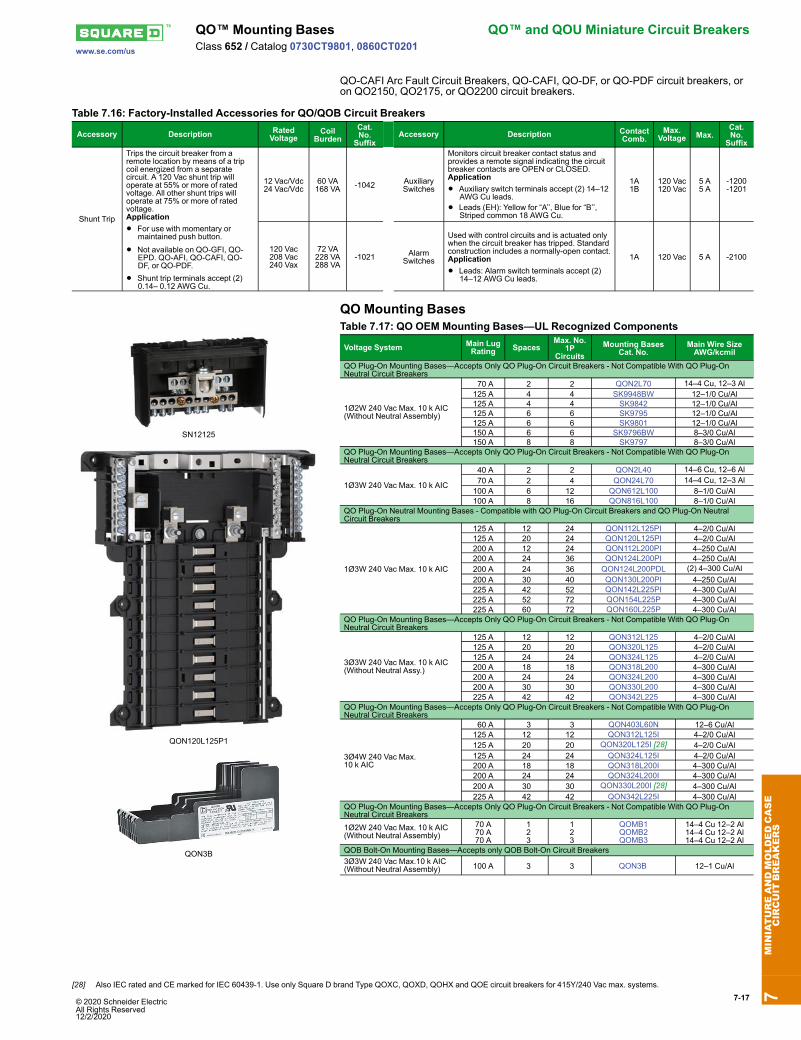
QO Plug-On Mounting Bases—Accepts Only QO Plug-On Circuit Breakers - Not Compatible With QO Plug-OnNeutral Circuit Breakers
1Ø2W 240 Vac Max. 10 k AIC(Without Neutral Assembly)
70 A 2 2 QON2L70 14–4 Cu, 12–3 Al125 A 4 4 SK9948BW 12–1/0 Cu/Al125 A 4 4 SK9842 12–1/0 Cu/Al125 A 6 6 SK9795 12–1/0 Cu/Al125 A 6 6 SK9801 12–1/0 Cu/Al150 A 6 6 SK9796BW 8–3/0 Cu/Al150 A 8 8 SK9797 8–3/0 Cu/Al
QO Plug-On Mounting Bases—Accepts Only QO Plug-On Circuit Breakers - Not Compatible With QO Plug-OnNeutral Circuit Breakers
1Ø3W 240 Vac Max. 10 k AIC
40 A 2 2 QON2L40 14–6 Cu, 12–6 Al 70 A 2 4 QON24L70 14–4 Cu, 12–3 Al100 A 6 12 QON612L100 8–1/0 Cu/Al100 A 8 16 QON816L100 8–1/0 Cu/Al
QO Plug-On Neutral Mounting Bases - Compatible with QO Plug-On Circuit Breakers and QO Plug-On NeutralCircuit Breakers
1Ø3W 240 Vac Max. 10 k AIC
125 A 12 24 QON112L125PI 4–2/0 Cu/Al125 A 20 24 QON120L125PI 4–2/0 Cu/Al200 A 12 24 QON112L200PI 4–250 Cu/Al200 A 24 36 QON124L200PI 4–250 Cu/Al200 A 24 36 QON124L200PDL (2) 4–300 Cu/Al200 A 30 40 QON130L200PI 4–250 Cu/Al225 A 42 52 QON142L225PI 4–300 Cu/Al225 A 52 72 QON154L225P 4–300 Cu/Al225 A 60 72 QON160L225P 4–300 Cu/Al
QO Plug-On Mounting Bases—Accepts Only QO Plug-On Circuit Breakers - Not Compatible With QO Plug-OnNeutral Circuit Breakers
3Ø3W 240 Vac Max. 10 k AIC(Without Neutral Assy.)
125 A 12 12 QON312L125 4–2/0 Cu/Al125 A 20 20 QON320L125 4–2/0 Cu/Al125 A 24 24 QON324L125 4–2/0 Cu/Al200 A 18 18 QON318L200 4–300 Cu/Al200 A 24 24 QON324L200 4–300 Cu/Al200 A 30 30 QON330L200 4–300 Cu/Al225 A 42 42 QON342L225 4–300 Cu/Al
QO Plug-On Mounting Bases—Accepts Only QO Plug-On Circuit Breakers - Not Compatible With QO Plug-OnNeutral Circuit Breakers
3Ø4W 240 Vac Max.10 k AIC
60 A 3 3 QON403L60N 12–6 Cu/Al125 A 12 12 QON312L125I 4–2/0 Cu/Al125 A 20 20 QON320L125I [28] 4–2/0 Cu/Al125 A 24 24 QON324L125I 4–2/0 Cu/Al200 A 18 18 QON318L200I 4–300 Cu/Al200 A 24 24 QON324L200I 4–300 Cu/Al200 A 30 30 QON330L200I [28] 4–300 Cu/Al225 A 42 42 QON342L225I 4–300 Cu/Al
QO Plug-On Mounting Bases—Accepts Only QO Plug-On Circuit Breakers - Not Compatible With QO Plug-OnNeutral Circuit Breakers1Ø2W 240 Vac Max. 10 k AIC(Without Neutral Assembly)
70 A70 A70 A
123
123
QOMB1QOMB2QOMB3
14–4 Cu 12–2 Al14–4 Cu 12–2 Al14–4 Cu 12–2 Al
QOB Bolt-On Mounting Bases—Accepts only QOB Bolt-On Circuit Breakers3Ø3W 240 Vac Max.10 k AIC(Without Neutral Assembly) 100 A 3 3 QON3B 12–1 Cu/Al
7MINIATUREANDMOLDEDCASE
CIRCUIT
BREAKERS
[28] Also IEC rated and CE marked for IEC 60439-1. Use only Square D brand Type QOXC, QOXD, QOHX and QOE circuit breakers for 415Y/240 Vac max. systems.
Table 7.19: Accessories for US Mounting Base for UL489 C60Description Cat. No.
Main lug kit for US mounting bases, 1 lug per kit, for 6 AWG to 300 kcmil cable USMBLKTerminal cover for US mounting base; provides IP20 ingress protection per IEC 60529; suitable forjumper bars or cable USMBTC
QOU unit mount miniature circuit breakers (cable-in/cable-out) are ideal for OEMapplications. They have the Square D™ circuit breaker’s unique Visi-Trip™ feature andcan be DIN rail-mounted or surface- or flush-mounted using mounting feet. Mounting feetnot provided [29].General Specifications Common to All Low Ampere QOU Circuit Breakers• For convenient flush mount, surface mount or DIN mount(symmetrical rail 35 x 7.5 DIN/EN 50 022)
• Single handle with internal common trip• Terminal lug wire size (1) 14–2 AWG Cu or Al• Reversible line and load lugs• Field-installable quick connectors• UL Listed 48 Vdc (5 k AIR)• UL Listed as HACR Type: 10–70 A• High magnetic trip circuit breakers (QOU-HM) are recommended for applicationswhere high initial inrush may occur and for individual dimmer applications.
• For DIN mounting rails, see IEC Starters and Relays, Section 18.
Class 720 / Refer to Catalog 0730CT9801High Ampere QOU Circuit Breakers
High Ampere QOU
General Specifications Common to All High Ampere QOU Circuit Breakers• Flush mount, surface mount, and DIN rail mount.• Internal common trip.• Non-reversible line and load lugs.• Terminal lug wire size (1) 12– 2/0 AWG Cu or Al.• UL Listed 60 Vdc per pole (5 k AIR). (Note: except switches)• UL Listed as HACR type, 80–125 A.• Non-automatic switches have the same physical packaging as miniature circuitbreakers, but provide no overcurrent or short circuit protection. They are UL Listed perUL1087 and are CSA certified.
Table 7.23: QOU High Ampere Miniature Circuit Breakers (10 k AIR)AmpereRating
Table 7.25: Accessories for QOU Low Ampere Circuit Breakers (Except as Noted)Description Order
Qty. Cat. No.
Factory-installed ring tongue terminal, 10–32 screw, for 1P, 2P, 3P QOU, 10–60 A — Suffix -5283Hex drive 5/32 in. wire binding screw for QOU — Suffix -5280For padlocking 1P low ampere QOU circuit breaker in OFF or ON position — QOU1PAFor padlocking 2P and 3P low ampere QOU circuit breaker in OFF or ON position — QOU1PLFor padlocking 1P low ampere QOU circuit breaker in OFF position only — QOU1PAFLAFor padlocking 2P and 3P low ampere QOU circuit breaker in OFF position only — QOU2PAFLAFor padlocking 2P and 3P high ampere QOU circuit breaker in OFF position only — Suffix -7100Handle lock-out, ON or OFF position — HLO14P 100 A Jumper bar assy. w/front wiring with base, cover and screw 1 QOU14100JBAF4P 100 A Jumper bar assy. w/right side wiring with base, cover and screw 1 QOU14100JBAR4P 100 A Jumper bar assy. w/left side wiring with base, cover and screw 1 QOU14100JBAL1Ø, 4P, 100 A Jumper bar base with front wiring 40 QOU14100BAFB1Ø, 4P, 100 A Jumper bar base with left side wiring 40 QOU14100BALB1Ø, 4P, 100 A Jumper bar base with right side wiring 40 QOU14100BARB4P Jumper bar cover 40 QOU14100CABMounting screw for jumper bar cover 40 QOU1CMSB6P 150 A Jumper bar assy. w/front wiring with base, cover and screw 1 QOU16150JBAF1Ø, 6P, 150 A Jumper bar base with front wiring 40 QOU16150BAFB1Ø, 6P, 150 A Jumper bar base with left side wiring 40 QOU16150BALB1Ø, 6P, 150 A Jumper bar base with right side wiring 40 QOU16150BARB6P jumper bar cover 40 QOU16150CAB
Vertical rainproof cover 2P and 3P QO, QOU, FA and KA 110
1P Fingersafe™ cover for high ampere QOU circuit breaker 140
QOUHFSC1QOUHFSC1B
1P Fingersafe cover for low ampere QOU circuit breaker 140
QOULFSC1QOULFSC1B
Cover plate for one 2P QOU circuit breaker 140
QOUCP2QOUCP2B
Cover plate for one 3P QOU circuit breaker 140
QOUCP3QOUCP3B
Cover plate for two 2P QOU circuit breakers 140
QOUCP4QOUCP4B
Cover plate for three 2P QOU circuit breakers 140
QOUCP6QOUCP6B
Field-installable ring tongue terminal adaptor 180
QOURTQOURTB
Quick connector end connection wiring 140
QOUECQOUECB
Quick connector forward or reverse wiring 140
QOUFRQOUFRB
1P QOU mounting foot 180
QOUMF1[31]QOUMF1B [31]
2P QOU mounting foot 140
QOUMF2 [31]QOUMF2B [31]
3P QOU mounting foot 124
QOUMF3 [31]QOUMF3B [31]
Tapped mounting foot for QOU, 1P and 2P 10–70 A, 3P 10–60 APackaged with circuit breaker Suffix -3100Individually packaged 1 QOUMFS1Bulk packed 80 QOUMFS1B
Mechanical interlock attachment: Used to interlock two circuit breakers mountedside-by-side so that only one circuit breaker can be ON at a time. A 1P or 2P circuitbreaker can be mounted on the left and interlocked with a 2P or 3P circuit breakeron the right.
1 QOU2DTILA [32]
QOUQ Low Ampere Circuit Breakers
QOUQ low ampere circuit breakers with four-point quick-connect terminals are providedwith permanent factory-installed terminals which are affixed to the Load or OFF end ofthe circuit breaker. This special terminal will accommodate up to four 1/4-inch insulatedfemale quick connect wire terminations. Total ampacity of these connections must notexceed the rating of the circuit breaker.
Table 7.26: QOUQ Four-Point Quick-Connect TerminalsPoles Order Qty. Cat. No.
Four-Point Quick-Connect Terminals1 1
Change QOU toQOUQ2 1
3 1
The QOU uses the same electrical accessories as the QO. See the QO information for available electricalaccessories.
7MINIATUREANDMOLDEDCASE
CIRCUIT
BREAKERS
[31] For use on low and high ampere QOU.[32] 10–70 A 1P and 2P, 10–60 A 3P.
The Square D Homeline circuit breakers are in a 1 in. wide format for 1-pole circuitbreakers. They are designed to plug into Homeline load centers.
Table 7.27: Standard HOM Plug-on Circuit BreakersAmpereRating AIR 1P—120 Vac,
1 Space Required2P—120/240 Vac Common Trip
2 Spaces Required. 15 A 10 kA HOM115 [1][2] HOM215 [2] 20 A 10 kA HOM120 [1][2] HOM220 [2] 25 A 10 kA HOM125 [2] HOM225 [2] 30 A 10 kA HOM130 [2] HOM230 [2] 35 A 10 kA — HOM235 [2] 40 A 10 kA HOM140 [2] HOM240 [2] 45 A 10 kA — HOM245 [2] 50 A 10 kA HOM150 [2] HOM250 [2] 60 A 10 kA — HOM260 [2] 70 A 10 kA — HOM270 [2] 80 A 10 kA — HOM280 [2] 90 A 10 kA — HOM290 [2]100 A 10 kA — HOM2100 [2]110 A 10 kA — HOM2110 [2]125 A 10 kA — HOM2125 [2]150 A 10 kA — HOM2150BB [2][3]175 A 10 kA — HOM2175BB [2][3]200 A 10 kA — HOM2200BB [2][3]
Homeline High Magnetic Circuit Breakers (HOM-HM)High magnetic trip circuit breakers are recommended for applications where high initialinrush current may occur.
Table 7.28: HOM-HM Circuit BreakersAmperes 1P—120/240 Vac 2Ps15 A HOM115HM [4] —20 A HOM120HM [2] —
Homeline Combination Arc Fault Circuit Interrupters—Provide overload and short circuitprotection, plus arc fault protection in accordance with the NEC and UL1699.
Table 7.29: HOM-CAFI Circuit BreakersCircuit Breaker Type Ampere Rating Poles
120 Vac Cat. No.One-Pole
Combination Arc-Fault CircuitInterrupter with Pigtail Neutral
15 A 1 HOM115CAFI [2]20 A 1 HOM120CAFI [2]
Plug-On Neutral CombinationArc-Fault Interrupter
15 A 1 HOM115PCAFI [2]20 A 1 HOM120PCAFI [2]
Two-PoleCombination Arc-Fault CircuitInterrupter with Pigtail Neutral
15 A 2 HOM215CAFI [2] [5]20 A 2 HOM220CAFI [2] [5]
Homeline Dual Function Circuit Breaker (HOM-DF)
HOM 1P DFPlug-on Neutral
HOM 1P DFPigtail
Homeline Combination Arc Fault and Ground Fault Circuit Interrupters (Dual Function)—Provide overload and short circuit protection, plus arc fault and ground fault protection ina single device in accordance with the NEC, UL1699 and UL943.
Table 7.30: HOM-DF Circuit BreakersCircuit Breaker Type Ampere
RatingPoles120 Vac Cat. No.
Combination Arc-Fault and Ground Fault CircuitInterrupter with Pigtail Neutral
15 A 1 HOM115DF [2]20 A 1 HOM120DF [2]
Plug-On Neutral CombinationArc-Fault and Ground Fault
Circuit Interrupter
15 A 1 HOM115PDF [2]
20 A 1 HOM120PDF [2]7MINIATUREANDMOLDEDCASE
CIRCUIT
BREAKERS [1] UL Listed as SWD (switching duty) rated. Suitable for switching 120 Vac fluorescent lighting loads.
[2] UL Listed as HACR type for use with air conditioning, heating and refrigeration equipment haing motor group combinations and marked for use with HACR type circuit breakers.[3] Requires four spaces (1 AWG–300 kcmil Al/Cu). Use only in 1Ø panel rated 150 A or greater.[4] This product is discontinued.[5] For 120/240 V only, not for 208Y/120 V.
HOM 1P GFI(With Ground FaultCircuit Interrupter)1 Space Required
HOM 2P GFI(With Ground FaultCircuit Interrupter)2 Spaces Required
HOM-GFI circuit breakers provide overload and short circuit protection, combined withClass A ground fault protection. Class A denotes a ground fault circuit interrupter that willtrip when a fault current to ground is 6 milliamperes or more.
Table 7.31: HOM-GFI Circuit Breakers
Circuit Breaker Type AmpereRating AIR 1P—120 Vac
1 Space Required2P—120/240 VacCommon Trip
2 Spaces Required
Ground-Fault CircuitInterrupter(Pigtail
Neutral)
15 A 10 kA HOM115GFI HOM215GFI20 A 10 kA HOM120GFI HOM220GFI25 A 10 kA — HOM225GFI30 A 10 kA — HOM230GFI35 A 10 kA — HOM235GFI40 A 10 kA — HOM240GFI45 A 10 kA — HOM245GFI50 A 10 kA — HOM250GFI
Plug-On Neutral Ground-Fault Circuit Interrupter
15 A 10 kA HOM115PGFI[6] —20 A 10 kA HOM120PGFI[6] —
Homeline Equipment Protection Device (HOM-EPD)Homeline Equipment Protection Device—Circuit Breakers with 30 mA EquipmentGround Fault Protection (UL Listed).
Common Trip15 A HOM115EPD HOM215EPD [7]20 A HOM120EPD HOM220EPD25 A — HOM225EPD30 A — HOM230EPD40 A — HOM240EPD50 A — HOM250EPD
Homeline Tandem and Quad Tandem Circuit Breakers (HOMT)Table 7.33: HOMT Tandem Circuit Breakers
Ampere Rating [8] AIR 1P Tandem—120/240 Vac (One Space Required)15 and 15 A 10 kA HOMT1515 [9]15 and 20 A 10 kA HOMT1520 [9]20 and 20 A 10 kA HOMT2020 [9]30 and 15 A 10 kA HOMT3015 [9]30 and 20 A 10 kA HOMT3020 [9]
HOMT QuadCircuit Breaker
2 Spaces Required
Table 7.34: HOMT Quad Tandem 1P Circuit BreakersAmpere Rating [8]
AIR 2P Tandem—120/240 Vac(Two Spaces Required)1P 2P
(2) 15 A 15 A 10 kA HOMT1515215(2) 15 A 20 A 10 kA HOMT1515220(2) 15 A 25 A 10 kA HOMT1515225 [7](2) 15 A 30 A 10 kA HOMT1515230(2) 15 A 40 A 10 kA HOMT1515240(2) 15 A 50 A 10 kA HOMT1515250(2) 20 A 20 A 10 kA HOMT2020220(2) 20 A 25 A 10 kA HOMT2020225(2) 20 A 30 A 10 kA HOMT2020230(2) 20 A 40 A 10 kA HOMT2020240(2) 20 A 50 A 10 kA HOMT2020250
NOTE: Typical catalog no. (e.g. HOMT 1515230) represents two 1P, outer poles (two15 A 1P CBs) and one 2P inner circuit breaker with common trip (one 30 A 2P CB).
Table 7.35: HOMT Quad Tandem 2P Circuit BreakersAmpere Rating [8]
AIR (2) 2P Tandem—120/240 Vac(Two Spaces Required)2P 2P
15 A 15 A 10 kA HOMT21521515 A 20 A 10 kA HOMT21522015 A 25 A 10 kA HOMT21522515 A 30 A 10 kA HOMT21523015 A 40 A 10 kA HOMT21524015 A 50 A 10 kA HOMT21525020 A 20 A 10 kA HOMT22022020 A 25 A 10 kA HOMT22022520 A 30 A 10 kA HOMT22023020 A 40 A 10 kA HOMT22024020 A 50 A 10 kA HOMT22025025 A 25A 10 kA HOMT22522525 A 30 A 10 kA HOMT22523025 A 40 A 10 kA HOMT22524025 A 50 A 10 kA HOMT22525030 A 30 A 10 kA HOMT230230
7MINIATUREANDMOLDEDCASE
CIRCUIT
BREAKERS
[6] New Plug-on Neutral[7] This product is discontinued.[8] 15–20 A tandem or quad tandem circuit breakers are suitable for use with 60oC or 75oC conductors. 25–50 A tandem or quad tandem circuit breakers are suitable for use with 75oC
conductors only.[9] UL Listed as HACR type for use with air conditioning, heating and refrigeration equipment haing motor group combinations and marked for use with HACR type circuit breakers.
AIR (2) 2P Tandem—120/240 Vac(Two Spaces Required)2P 2P
30 A 40 A 10 kA HOMT23024030 A 50 A 10 kA HOMT230250
NOTE: Typical catalog no. (i.e. HOMT215230) represents two 2P; outer poles (one15 A 2P with common trip) and inner poles (one 30 A 2P with common trip).
Breaker Type Ampere RatingWire Size (AWG/kcmil) [11]
Aluminum Copper
HOM1P
15–30 A 14–8 AWG 14–8 AWG or(2) 14–10 AWG
40–50 A 8–2 AWG 8–2 AWG
HOM2P
15–30 A 14–8 AWG 14–8 AWG or(2) 14–10 AWG
35–70 A 8–2 AWG 8–2 AWG 80–125 A 4–2/0 AWG 4–2/0 AWG150–200 A 4 AWG–300 kcmil 4 AWG–300 kcmil
HOMTand Quad 15–30 A 14–8 AWG 14–8 AWGQuad Only 40–50 A 6–12 AWG 6–14 AWG
HOM-GFI - 1P 15–20 A 14–10 AWG 14–10 AWGHOM-GFI - 2P 15–50 A 12–4 AWG 14–6 AWG
Accessories for Homeline Circuit BreakersTable 7.37: Accessories for Use with Homeline Circuit Breakers
Description Cat. No.Handle AttachmentsHandle Tie: Converts any two adjacent 120/240 Vac single HOM circuit breakers to independent trip 2P HOM1HTHandle Tie: Converts any two adjacent 120/240 Vac1P side-by-side HOMTcircuit breakers to independent trip 2P HOMTHT
Handle Clamp: Clamp for holding HOM 1P handle in the ON or OFF position QO1LOHandle Blocking Device: Attaches to standard HOM 2P circuit breakers for holding the handle in the OFF position HOM2HBDHandle Padlock Attachment: For padlocking 1P Standard HOM breakers in the ON or OFF position HOM1PA
Handle Padlock Attachment: Forpadlocking 2P Standard HOM circuit breakers in ON or OFF position
15–70 A HOM2PALA80–125 A HOM2PAHA150–200 A HOM2PAVHA
Handle Padlock Attachment: For padlocking 1P CAFI, DF, GFI, and EPD HOM breakers in ON or OFF position HOMELEC1PAHandle Padlock Attachment: For padlocking 2P CAFI, GFI, and EPD HOM breakers in ON or OFF position HOMELEC2PALAHandle Padlock Attachment: For padlocking center poles of Homeline Quad breakers in the OFF position HOMQPA
Handle Padlock Attachment: For padlocking main circuit breakers in convertible load center in OFF position 50–125 A QOM1PA [12]100–225 A QOM2PA [12]
Sub-Feed Lugs125 A 2P plug-on—2 spaces required HOML2125225 A 2P plug-on—4 spaces required HOML2225 [13]
7MINIATUREANDMOLDEDCASE
CIRCUIT
BREAKERS [10] 15–20 A tandem or quad tandem circuit breakers are suitable for use with 60oC or 75oC conductors. 25–50 A tandem or quad tandem circuit breakers are suitable for use with 75oC
conductors only.[11] 15–30 A circuit breakers are suitable for use with 60oC or 75oC conductors. 40–125 A circuit breakers are suitable for use with 75oC conductors.[12] 50–125 A QOM1 frame size; 100–225 A QOM2 frame size.[13] Requires four spaces (1 AWG–300 kcmil Al/Cu). Use only in 1Ø panel rated 150 A or greater.
C60BP and C60BPR are multi-standard miniature circuit breakers and branch circuitprotection as defined by UL489. They combine the following functions:• circuit protection against short-circuit curves• circuit protection against overload currents• tripping and fault indication by the addition of auxiliary accessories
C60SP circuit breakers are multi-standard miniature circuit beakers and supplementaryprotection as defined by UL1077. They combine the following functions:• circuit protection against short-circuit curves• circuit protection against overload currents• tripping and fault indication by the addition of auxiliary accessories
C60H-DC circuit breakers are multi–standard miniature circuit beakers and supplementaryprotection as defined by UL1077, dedicated to direct current applications. They combinethe following functions:• circuit protection against short-circuit curves• circuit protection against overload currents• tripping and fault indication by the addition of auxiliary accessories
UL 1053 residual current circuit breakers already protected upstream by a short circuitand overload protection device are used for:• control and disconnection of electric circuits• protection of people against electric shock by direct and indirect contacts• protection of installations against insulation faults• enhanced continuity of supply, during a series of close lightning strokes, ITearthingsystem, equipment including interference suppression filters, variable speedcontrollers, frequency converters, electronic ballasts for lighting
• enhanced earth leakage protection: in presence of harmonics or high frequencyejections.
A-SI type GFPs are ideal for operation in environments with a humid atmosphere and/orpolluted by aggressive agents: swimming pools, marinas, agri-food industries, watertreatment stations, industrial sites, etc.
Multi 9™ Miniature Circuit Breakers Multi 9 Circuit Breakers Busbar Offerwww.se.com/us
Class 860 / Refer to Catalog LVCATM9OEM_EN
C60BP (UL489) Comb Busbars
IEC
These comb busbars are aimed to be used only with C60BP circuit-breakers.They perform distribution and subdistribution of the electric power supply and allow rapidassembly and disassembly of equipment.
• The comb busbars make it easier to install C60BP UL489 circuit breakers.
• They must not be cut.• Comb busbar
power supply
• Verticalincomingfeeder
• Insulation of teethremaining free
• Ensuresthe correctcombbusbarinsulation
UsePower supply by insulated connector
• Use with rigid and flexible copper cable
• 6 to 35 mm2 (AWG #10 to #2):
Tighteningtorque: 3.5 N•m(31 lb.in.)
Standard Comb Busbars
Number of poles 1P 2P 3P All All —Catalogue numbers M9XUP106 M9XUP312 M9XUP312 M9XUP312 M9XUP312 M9R81425 M9XUPC04 M9XCTC18 —Number of 18 mm modules 6 12 6 12 6 12 — — —Set of 1 1 1 4 5 x 3 —Cuttable Comb Busbars
Number of poles x 1P 2P 3P 1P+Aux 3P+Aux All All —Catalogue numbers M9XCP157 M9XCP256 M9XCP357 M9XCA137 M9XCA348 M9XCPC04 M9XUTC18 M9XCEC10Number of 18 mm modules 57 56 57 37 37 — — —Set of 1 1 1 1 1 4 5 x 3 —Technical SpecificationsAcceptable current at 40°C(Ie)
Standard comb busbars: 115 ACuttable comb busbars: 80 A
Resistance to short-circuitcurrents
Compatible with the breaking capacity of Schneider Electric modular circuit breakers
Voltage rating (Ue) 480Y/277 VInsulation voltage (Ui) 1000 VACPollution degree 3Fire resistance Self-extinguishability 960°C 30 s/30 sColour RAL 7035Standards UL508
Multi 9 Circuit Breakers Busbar Offer Multi 9™ Miniature Circuit BreakersClass 860 / Refer to Catalog LVCATM9OEM_EN
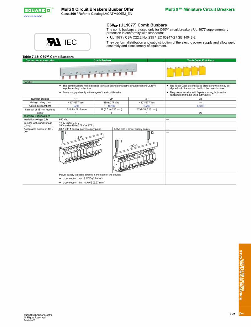
C60SP (UL1077) Comb Busbars
IEC
The comb busbars are used only for C60SP circuit breakers UL 1077 supplementaryprotection in conformity with standards:• UL 1077 / CSA C22.2 No. 235 / IEC 60947-2 / GB 14048-2.They perform distribution and subdistribution of the electric power supply and allow rapidassembly and disassembly of equipment.
120 to 480Y/277 Vac; 30, 100, and 300 mA; 2P and 4Ps.See Multi 9 GFP Ground Fault Protectors, page 7-27
or Catalog LVCATM9OEM_EN
Table 7.45: Multi 9 C60 Mechanical AccessoriesDescriptions C60 Cat. No.
Ring tongue terminal kit for UL1077 C60 For one pole M9A17400Spacer for DIN rail, Not UL Recognized 9 mm wide 27062Padlock Attachment (1 per for 1P, 2P, 3P or 4P) 2 per pack 26970Heavy-duty Padlock Attachment for C60, Locks OFF only 2 per pack M9PAFPadlocking Device Left Side Mount, Locks OFF only [1]
1 per pack MGN26380Padlocking Device Right Side Mount, Locks OFF only [2] MGN26381
Front Mounting Kit
1P MG269832P MG269843P MG269854P MG26989
Terminal Screw Shield (Not UL Recognized) Bag of two4P shields 26981
Terminal cover (Not UL Recognized)
1P 269752P 26976
3P 26975 +26976
4P 26978Rotary Handle for C60 (Non UL Recognized)Operating Subassembly
2P/3P/4P27046
Door Interlock Handle 27047Fixed Handle (Front or Lateral) 27048Multi-pole Front Mounting KitRail Support (20 of 9 mm modules) 14211Hinged Transparent Cover 14210
7MINIATUREANDMOLDEDCASE
CIRCUIT
BREAKERS
[1] Left-side mounted padlocking device cannot be used in conjunction with accessories SD, OF, MX or MN. Use right-side mounted padlocking device when accessories are required.[2] Right-side mounted padlocking device cannot be used in conjunction with VIGI module. Use left-side mounted padlocking device when VIGI Module is required.
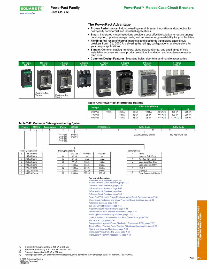
PowerPact Family PowerPact™ Molded Case Circuit BreakersClass 611, 612
The PowerPact Advantage• Proven Performance: Industry-leading circuit breaker innovation and protection forheavy-duty commercial and industrial applications.
• Smart: Integrated metering options provide a cost-effective solution to reduce energyconsumption, optimize energy costs, and improve energy availablility for your facilities.
• Flexible: Full range of thermal-magnetic and electronic trip molded case circuitbreakers from 15 to 3000 A, delivering the ratings, configurations, and operators foryour unique applications.
• Simple: Common catalog numbers, standardized ratings, and a full range of field-installable accessories make product selection, installation and maintenance easierthan ever.
• Common Design Features: Mounting holes, door trim, and handle accessoriesB-Frame125 A
B D G J K L R240 Vac 10 kA 25 kA 65 kA 100 kA 65 kA [1] 125 kA 200 kA480 Vac — 18 kA 35 kA 65 kA 65 kA [2] 100 kA 200 kA600 Vac — 14 kA 18 kA 25 kA 65 kA [2] 50 kA [3] 100 kA
Table 7.47: Common Catalog Numbering SystemFrame Rating Termination Poles Voltage Amperage[4] Suffix Code Suffix CodeH G L 3 6 1 5 0 A B S A
1=1Pole2=2Pole3=3Pole4=4Pole
4=480 V6=600 V
2A/2B Auxiliary Switch 110 Vac Shunt Trip
Frame Designation Interrupting Rating TerminationsB 125 A Frame 240 Vac 480 Vac 600Vac A I-LineH 150 A Frame B 10 kA — — L Lugs on Both EndsJ 250 A Frame D 25 kA 18 kA 14 kA F Bus Bar (No Lugs)Q 250 A Frame G 65 kA 35 kA 18 kA M Lugs Line Side OnlyL 600 A Frame J 100 kA 65 kA 25 kA P Lugs Load End OnlyM 800 A Frame K 100 kA 65 kA 65 kA N Plug-inP 1200 A Frame L 125 kA 100 kA 50 kA D DrawoutR 3000 A Frame R 200 kA 200 kA 100 kA S Rear Connected Studs
For more information:B-Frame Circuit Breakers, page 7-32H- and J-Frame Circuit Breakers, page 7-33Q-Frame Circuit Breakers, page 7-36L-Frame Circuit Breakers, page 7-38P-Frame Circuit Breakers, page 7-41R-Frame Circuit Breakers, page 7-42PowerPact™ H- and J-Frame Electronic Motor Circuit Protectors, page 7-48Motor Circuit Protectors and Motor Protector Circuit Breakers, page 7-50Automatic Switches, page 7-46500 Vdc Circuit Breakers, page 7-45Mission Critical Circuit Breakers, page 7-44PowerPact™ Circuit Breaker Accessories, page 7-51Motor Operators and Rotary Handles, page 7-52Locks, Installation Accessories, and Rear Connections, page 7-54Mechanical Lugs, page 7-54Compression Lugs and Power Distribution Connectors (PDC), page 7-57Terminal Nuts, Terminal Pads, Terminal Shields and Accessories, page 7-59Plug-In and Drawout Mountings, page 7-60MicroLogic™ Electronic Trip Units, page 7-61MicroLogic™ Trip Unit Accessories, page 7-64
7MINIATUREANDMOLDEDCASE
CIRCUIT
BREAKERS
[1] B-frame K interrupting rating is 100 kA at 240 Vac[2] P-frame K interrupting is 50 kA at 480 and 600 Vac.[3] P-frame L interrupting is 25 kA at 600 Vac.[4] For amperage of M,-, P- or R-frame circuit breakers, add a zero to the three amperage digits; for example, 120 = 1200 A.
PowerPact™ Molded Case Circuit Breakers B-Frame Circuit Breakerswww.se.com/us
Class 0613
PowerPact B-Frame Molded Case Circuit Breakers (125 A)
B-FrameThermal-Magnetic Trip Unit
With EverLink LugTechnology
PowerPact B-frame circuit breakers provides economical thermal-magnetic circuitprotection in a compact size.• Fixed 15-125 A thermal-magnetic protection up to 600Y/347 Vac and 250 Vdc• 1- to 4-pole unit mount construction; 1- to 3-pole I-Line construction• UL listed interrupting ratings from 18 kA to 65 kA at 480 Vac• EverLink lugs, a cable connection method that helps maintain low resistanceconnections
• UL, CSA, NOM, IEC, CCC certified and CE marked for global acceptance
Table 7.49: B-Frame Termination OptionsTermination LetterA = I-Line (See Section 9, Panelboards) B D L 3 6 1 0 0
For factory-installedtermination, placetermination letter inthe third block of thecircuit breaker catalognumber.
F = No Lugs (includes terminal nut kit on bothends)L =EverLink Lugs both endsM = Lugs ON end Terminal Nut Kit OFF endP = Lugs OFF end Terminal Nut Kit ON end
480Y/277 Vac 18 kA 35 kA 65 kA 65 kA480 Vac 18 kA 35 kA 65 kA 65 kA
600Y/347 Vac 14 kA 18 kA 25 kA 65 kA125 Vdc 10 kA 20 kA 50 kA —250 Vdc 10 kA 20 kA 50 kA —
Table 7.51: B-Frame Lug OptionsLug Option SuffixNo Suffix = EverLink Lugs both ends B D L 3 6 1 0 0 LU
For factory-installedlug option, place suffixafter the amperage inthe circuit breakercatalog number.
LU = EverLink Lug with Control WireTerminal ON end; EverLink Lug OFF endLV = EverLink Lug ON end; EverLink Lugwith Control Wire Terminal OFF endLW = EverLink Lug with Control WireTerminal both endsLC = Copper Mechanical Lugs both endsLH = Aluminum Mechanical Lugs both ends
Table 7.52: PowerPact B-Frame 125 A Magnetic Trip ValuesCurrent Rating @
40o CFixed AC Magnetic Trip
Hold Trip15 A 400 A 600 A20 A 400 A 600 A25 A 480 A 720 A30 A 480 A 720 A35 A 480 A 720 A40 A 480 A 720 A45 A 480 A 720 A50 A 480 A 720 A60 A 640 A 960 A70 A 800 A 1200 A80 A 800 A 1200 A90 A 1000 A 1500 A100 A 1000 A 1500 A110 A 1000 A 1500 A125 A 1000 A 1500 A
Accessories see page 7-51Optional Lugs see page 7-56Dimensions see page 7-84
H- and J-Frame Circuit Breakers PowerPact™ Molded Case Circuit BreakersClass 611 / Refer to Catalog 0611CT1001
PowerPact H- and J-Frame Molded-Case Circuit Breakers (150 Aand 250 A)
J-FrameMicroLogic™ Trip Unit J-Frame 3–Pole
Thermal-Magnetic Trip Unit
A flexible, high performance offer certified to global standards.• Thermal magnetic or MicroLogic™ trip protection from 15–250 A up to 600 Vac and250 Vdc
• 2 and 3-pole unit mount and I-Line constructions[5]• High performance UL listed interrupting ratings from 18 to 200 kA at 480 Vac• H- and J-Frame have common mounting holes, handle locations and trim dimensionswith many shared accessories and auxiliaries.
• UL, CSA, NOM, IEC, CCC certified and CE marked for global acceptance.
Table 7.53: Lug Kit Wire RangesSensor Rating Standard Lug Kit Terminal Wire Range60–150 A AL150HD 14–3/0 AWG Al or Cu250 A AL250JD. 3/0 AWG–350 kcmil Al or Cu
Table 7.54: H- and J-Frame Interrupting RatingsVoltage Interrupting Rating
D G J L R240 Vac 25 kA 65 kA 100 kA 125 kA 200 kA480 Vac 18 kA 35 kA 65 kA 100 kA 200 kA600 Vac 14 kA 18 kA 25 kA 50 kA 100 kA
250 Vdc[6] 20 kA 20 kA 20 kA 20 kA —
Table 7.55: H- and J-Frame Termination OptionsTermination Letter
A - I-Line (See Section 9—Panelboards) H D L 3 6 0 1 5For factory-installed termination, place terminationletter in the third block of the circuit breaker catalognumber.
F = No Lugs (includes terminal nut kit on both ends)L = Lugs both endsM = Lugs ON end Terminal Nut Kit OFF endP = Lugs OFF end Terminal Nut Kit ON endN = Plug-inD = DrawoutS = Rear Connected
Accessories see page 7-51Optional Lugs see page 7-56Dimensions see page 7-84Enclosures see page 7-85
7MINIATUREANDMOLDEDCASE
CIRCUIT
BREAKERS
[5] H- and J- frame circuit breakers can be used as a main or sub-feed circuit breaker in an NQ or NF panelboard.[6] Not available with electronic trip units.
PowerPact™ Molded Case Circuit Breakers H- and J-Frame Circuit Breakerswww.se.com/us
Class 611 / Refer to Catalog 0611CT1001
PowerPact H-Frame Thermal-Magnetic Circuit BreakersTable 7.56: Powerpact H-Frame 150 AThermal-Magnetic UL Current-Limiting [7] Circuit Breakers (600 Vac, 250 Vdc) [8]With FactorySealed Trip Unit Suitable for Reverse Connection [9]
CurrentRating @40o C
Fixed AC Magnetic TripInterrupting Rating
D G J [8] L [8]
Hold Trip Standard(80% Rated) 100% Rated Standard
(80% Rated) 100% Rated Standard(80% Rated) 100% Rated Standard
(80% Rated) 100% Rated
H-Frame, 150A 2P, 600 Vac 50/60 Hz, 250 Vdc [10]15 A 350 A 750 A HDL26015 HDL26015C HGL26015 HGL26015C HJL26015 HJL26015C HLL26015 HLL26015C20 A 350 A 750 A HDL26020 HDL26020C HGL26020 HGL26020C HJL26020 HJL26020C HLL26020 HLL26020C25 A 350 A 750 A HDL26025 HDL26025C HGL26025 HGL26025C HJL26025 HJL26025C HLL26025 HLL26025C30 A 350 A 750 A HDL26030 HDL26030C HGL26030 HGL26030C HJL26030 HJL26030C HLL26030 HLL26030C35 A 400 A 850 A HDL26035 HDL26035C HGL26035 HGL26035C HJL26035 HJL26035C HLL26035 HLL26035C40 A 400 A 850 A HDL26040 HDL26040C HGL26040 HGL26040C HJL26040 HJL26040C HLL26040 HLL26040C45 A 400 A 850 A HDL26045 HDL26045C HGL26045 HGL26045C HJL26045 HJL26045C HLL26045 HLL26045C50 A 400 A 850 A HDL26050 HDL26050C HGL26050 HGL26050C HJL26050 HJL26050C HLL26050 HLL26050C60 A 800 A 1450 A HDL26060 HDL26060C HGL26060 HGL26060C HJL26060 HJL26060C HLL26060 HLL26060C70 A 800 A 1450 A HDL26070 HDL26070C HGL26070 HGL26070C HJL26070 HJL26070C HLL26070 HLL26070C80 A 800 A 1450 A HDL26080 HDL26080C HGL26080 HGL26080C HJL26080 HJL26080C HLL26080 HLL26080C90 A 800 A 1450 A HDL26090 HDL26090C HGL26090 HGL26090C HJL26090 HJL26090C HLL26090 HLL26090C100 A 800 A 1700 A HDL26100 HDL26100C HGL26100 HGL26100C HJL26100 HJL26100C HLL26100 HLL26100C110 A 900 A 1700 A HDL26110 HDL26110C HGL26110 HGL26110C HJL26110 HJL26110C HLL26110 HLL26110C125 A 900 A 1700 A HDL26125 HDL26125C HGL26125 HGL26125C HJL26125 HJL26125C HLL26125 HLL26125C150 A 900 A 1700 A HDL26150 HDL26150C HGL26150 HGL26150C HJL26150 HJL26150C HLL26150 HLL26150C
H-Frame 150A 3P, 600 Vac 50/60 Hz, 250 Vdc15 A 350 A 750 A HDL36015 HDL36015C HGL36015 HGL36015C HJL36015 HJL36015C HLL36015 HLL36015C20 A 350 A 750 A HDL36020 HDL36020C HGL36020 HGL36020C HJL36020 HJL36020C HLL36020 HLL36020C25 A 350 A 750 A HDL36025 HDL36025C HGL36025 HGL36025C HJL36025 HJL36025C HLL36025 HLL36025C30 A 350 A 750 A HDL36030 HDL36030C HGL36030 HGL36030C HJL36030 HJL36030C HLL36030 HLL36030C35 A 400 A 850 A HDL36035 HDL36035C HGL36035 HGL36035C HJL36035 HJL36035C HLL36035 HLL36035C40 A 400 A 850 A HDL36040 HDL36040C HGL36040 HGL36040C HJL36040 HJL36040C HLL36040 HLL36040C45 A 400 A 850 A HDL36045 HDL36045C HGL36045 HGL36045C HJL36045 HJL36045C HLL36045 HLL36045C50 A 400 A 850 A HDL36050 HDL36050C HGL36050 HGL36050C HJL36050 HJL36050C HLL36050 HLL36050C60 A 800 A 1450 A HDL36060 HDL36060C HGL36060 HGL36060C HJL36060 HJL36060C HLL36060 HLL36060C70 A 800 A 1450 A HDL36070 HDL36070C HGL36070 HGL36070C HJL36070 HJL36070C HLL36070 HLL36070C80 A 800 A 1450 A HDL36080 HDL36080C HGL36080 HGL36080C HJL36080 HJL36080C HLL36080 HLL36080C90 A 800 A 1450 A HDL36090 HDL36090C HGL36090 HGL36090C HJL36090 HJL36090C HLL36090 HLL36090C100 A 800 A 1700 A HDL36100 HDL36100C HGL36100 HGL36100C HJL36100 HJL36100C HLL36100 HLL36100C110 A 900 A 1700 A HDL36110 HDL36110C HGL36110 HGL36110C HJL36110 HJL36110C HLL36110 HLL36110C125 A 900 A 1700 A HDL36125 HDL36125C HGL36125 HGL36125C HJL36125 HJL36125C HLL36125 HLL36125C150 A 900 A 1700 A HDL36150 HDL36150C HGL36150 HGL36150C HJL36150 HJL36150C HLL36150 HLL36150C
HJ and HL are UL certified as current limiting circuit breakers.
PowerPact J-Frame Thermal-Magnetic Circuit BreakersTable 7.57: J-Frame 250 AThermal-Magnetic UL Current-Limiting [11]Circuit Breakers (600 Vac, 250 Vdc) With Factory Sealed Trip UnitSuitable for Reverse Connection [9]
CurrentRating@ 40oC
Adjustable ACMagnetic Trip
Interrupting RatingD G J [11] L [11] R [11]
Low High Standard(80% Rated) 100% Rated Standard
(80% Rated) 100% Rated Standard(80% Rated) 100% Rated Standard
J-Frame 250 A 2P, 600 Vac 50/60 Hz, 250 Vdc[12]150 A 750 A 1500 A JDL26150 JDL26150C JGL26150 JGL26150C JJL26150 JJL26150C JLL26150 JLL26150C — —175 A 875 A 1750 A JDL26175 JDL26175C JGL26175 JGL26175C JJL26175 JJL26175C JLL26175 JLL26175C — —200 A 1000 A 2000 A JDL26200 JDL26200C JGL26200 JGL26200C JJL26200 JJL26200C JLL26200 JLL26200C — —225 A 1125 A 2250 A JDL26225 JDL26225C JGL26225 JGL26225C JJL26225 JJL26225C JLL26225 JLL26225C — —250 A 1250 A 2500 A JDL26250 JDL26250C JGL26250 JGL26250C JJL26250 JJL26250C JLL26250 JLL26250C — —
J-Frame 250 A 3P, 600 Vac 50/60 Hz, 250 Vdc150 A 750 A 1500 A JDL36150 JDL36150C JGL36150 JGL36150C JJL36150 JJL36150C JLL36150 JLL36150C JRL36150 JRL36150C175 A 875 A 1750 A JDL36175 JDL36175C JGL36175 JGL36175C JJL36175 JJL36175C JLL36175 JLL36175C JRL36175 JRL36175C200 A 1000 A 2000 A JDL36200 JDL36200C JGL36200 JGL36200C JJL36200 JJL36200C JLL36200 JLL36200C JRL36200 JRL36200C225 A 1125 A 2250 A JDL36225 JDL36225C JGL36225 JGL36225C JJL36225 JJL36225C JLL36225 JLL36225C JRL36225 JRL36225C250 A 1250 A 2500 A JDL36250 JDL36250C JGL36250 JGL36250C JJL36250 JJL36250C JLL36250 JLL36250C JRL36250 JRL36250C
JJ, JL and JR are UL certified as current limiting circuit breakers.
7MINIATUREANDMOLDEDCASE
CIRCUIT
BREAKERS
[7] Circuit breakers with J and L interrupting ratings are UL certified as current limiting.[8] Standard lug kit: AL150HD. Terminal wire range: 14–3/0 AWG Al or Cu.[9] See Supplemental Digest Section 3 for circuit breakers with field interchangeable trip units.[10] HD and HG circuit breakers are true two-pole construction.[11] Circuit breakers with J, L, and R interrupting ratings are UL certified as current limiting.[12] 2P in a 3P module
H- and J-Frame Circuit Breakers PowerPact™ Molded Case Circuit BreakersClass 611 / Refer to Catalog 0611CT1001
PowerPact H- and J-Frame Electronic Trip Current Limiting CircuitBreakers (150 A and 250 A)
H-FrameMicroLogic™ Trip Unit J-Frame
MicroLogic Trip Unit
rci
Mci
gol
oE
2.5
rI%A03>
03>
011>
.9
29.
39.
49.
59.
1
89.
79.
69.
Ir)oIx(
5.1
2
5.2
34
01
8
65
dsI)rIx(
H-Frame Circuit BreakerOptional FDM and IFM Module
Table 7.58: H-Frame 150 A and J-Frame 250 A Electronic Trip UL Current-Limiting [13] Standard (80% Rated) Circuit Breakers (600 Vac)With Factory Sealed Trip Unit [14] Suitable for Reverse Connection [15]
Electronic Trip Unit SensorRating
Interrupting Rating (80% Rated)Type Function Trip Unit D G J [13] L [13] R [13]
600 Vac, 50/60 Hz, 3P
MicroLogicStandard LI 3.2 [16]
60 A HDL36060U31X HGL36060U31X HJL36060U31X HLL36060U31X HRL36060U31X100 A HDL36100U31X HGL36100U31X HJL36100U31X HLL36100U31X HRL36100U31X150 A HDL36150U31X HGL36150U31X HJL36150U31X HLL36150U31X HRL36150U31X250 A JDL36250U31X JGL36250U31X JJL36250U31X JLL36250U31X JRL36250U31X
MicroLogicStandard LSI 3.2S [16]
[17]
60 A HDL36060U33X HGL36060U33X HJL36060U33X HLL36060U33X HRL36060U33X100 A HDL36100U33X HGL36100U33X HJL36100U33X HLL36100U33X HRL36100U33X150 A HDL36150U33X HGL36150U33X HJL36150U33X HLL36150U33X HRL36150U33X250 A JDL36250U33X JGL36250U33X JJL36250U33X JLL36250U33X JRL36250U33X
MicroLogicAmmeter LSI 5.2A
60 A HDL36060U43X HGL36060U43X HJL36060U43X HLL36060U43X HRL36060U43X100 A HDL36100U43X HGL36100U43X HJL36100U43X HLL36100U43X HRL36100U43X150 A HDL36150U43X HGL36150U43X HJL36150U43X HLL36150U43X HRL36150U43X250 A JDL36250U43X JGL36250U43X JJL36250U43X JLL36250U43X JRL36250U43X
MicroLogicEnergy LSI 5.2E
60 A HDL36060U53X HGL36060U53X HJL36060U53X HLL36060U53X HRL36060U53X100 A HDL36100U53X HGL36100U53X HJL36100U53X HLL36100U53X HRL36100U53X150 A HDL36150U53X HGL36150U53X HJL36150U53X HLL36150U53X HRL36150U53X250 A JDL36250U53X JGL36250U53X JJL36250U53X JLL36250U53X JRL36250U53X
MicroLogicAmmeter LSIG 6.2A [18]
60 A HDL36060U44X HGL36060U44X HJL36060U44X HLL36060U44X HRL36060U44X100 A HDL36100U44X HGL36100U44X HJL36100U44X HLL36100U44X HRL36100U44X150 A HDL36150U44X HGL36150U44X HJL36150U44X HLL36150U44X HRL36150U44X250 A JDL36250U44X JGL36250U44X JJL36250U44X JLL36250U44X JRL36250U44X
MicroLogicEnergy LSIG 6.2E
60 A HDL36060U54X HGL36060U54X HJL36060U54X HLL36060U54X HRL36060U54X100 A HDL36100U54X HGL36100U54X HJL36100U54X HLL36100U54X HRL36100U54X150 A HDL36150U54X HGL36150U54X HJL36150U54X HLL36150U54X HRL36150U54X250 A JDL36250U54X JGL36250U54X JJL36250U54X JLL36250U54X JRL36250U54X
Table 7.59: H-Frame 150 A and J-Frame 250 A Electronic Trip UL Current-Limiting [13] 100% Rated Circuit Breakers (600 Vac) With FactorySealed Trip Unit [14] Suitable for Reverse Connection [15]
Electronic Trip Unit SensorRating
Interrupting Rating (100% Rated)Type Function Trip Unit D G J [13] L [13] R [13]
600 Vac, 50/60 Hz, 3P[19]
MicroLogicStandard LI 3.2 [16]
60 A HDL36060CU31X HGL36060CU31X HJL36060CU31X HLL36060CU31X HRL36060CU31X100 A HDL36100CU31X HGL36100CU31X HJL36100CU31X HLL36100CU31X HRL36100CU31X150 A HDL36150CU31X HGL36150CU31X HJL36150CU31X HLL36150CU31X HRL36150CU31X250 A JDL36250CU31X JGL36250CU31X JJL36250CU31X JLL36250CU31X JRL36250CU31X
MicroLogicStandard LSI 3.2S [16]
[17]
60 A HDL36060CU33X HGL36060CU33X HJL36060CU33X HLL36060CU33X HRL36060CU33X100 A HDL36100CU33X HGL36100CU33X HJL36100CU33X HLL36100CU33X HRL36100CU33X150 A HDL36150CU33X HGL36150CU33X HJL36150CU33X HLL36150CU33X HRL36150CU33X250 A JDL36250CU33X JGL36250CU33X JJL36250CU33X JLL36250CU33X JRL36250CU33X
MicroLogicAmmeter LSI 5.2A
60 A HDL36060CU43X HGL36060CU43X HJL36060CU43X HLL36060CU43X HRL36060CU43X100 A HDL36100CU43X HGL36100CU43X HJL36100CU43X HLL36100CU43X HRL36100CU43X150 A HDL36150CU43X HGL36150CU43X HJL36150CU43X HLL36150CU43X HRL36150CU43X250 A JDL36250CU43X JGL36250CU43X JJL36250CU43X JLL36250CU43X JRL36250CU43X
MicroLogicEnergy LSI 5.2E
60 A HDL36060CU53X HGL36060CU53X HJL36060CU53X HLL36060CU53X HRL36060CU53X100 A HDL36100CU53X HGL36100CU53X HJL36100CU53X HLL36100CU53X HRL36100CU53X150 A HDL36150CU53X HGL36150CU53X HJL36150CU53X HLL36150CU53X HRL36150CU53X250 A JDL36250CU53X JGL36250CU53X JJL36250CU53X JLL36250CU53X JRL36250CU53X
MicroLogicAmmeter LSIG 6.2A [18]
60 A HDL36060CU44X HGL36060CU44X HJL36060CU44X HLL36060CU44X HRL36060CU44X100 A HDL36100CU44X HGL36100CU44X HJL36100CU44X HLL36100CU44X HRL36100CU44X150 A HDL36150CU44X HGL36150CU44X HJL36150CU44X HLL36150CU44X HRL36150CU44X250 A JDL36250CU44X JGL36250CU44X JJL36250CU44X JLL36250CU44X JRL36250CU44X
MicroLogicEnergy LSIG 6.2E
60 A HDL36060CU54X HGL36060CU54X HJL36060CU54X HLL36060CU54X HRL36060CU54X100 A HDL36100CU54X HGL36100CU54X HJL36100CU54X HLL36100CU54X HRL36100CU54X150 A HDL36150CU54X HGL36150CU54X HJL36150CU54X HLL36150CU54X HRL36150CU54X250 A JDL36250CU54X JGL36250CU54X JJL36250CU54X JLL36250CU54X JRL36250CU54X
Accessories see page 7-51Optional Lugs see page 7-56Dimensions see page 7-84Enclosures see page 7-85
7MINIATUREANDMOLDEDCASE
CIRCUIT
BREAKERS
[13] Circuit breakers with J, L, and R interrupting ratings are UL certified as current limiting.[14] See Supplemental Digest Section 3 for circuit breakers with field interchangeable trip units.[15] For applications requiring communications see page 7-64.[16] 3P circuit breakers with this trip unit can be used for 2P applications.[17] Fixed STand LT delays.[18] 3P circuit breakers with this trip unit can be used for 2P applications requiring ground fault protection. Additional metering capabilities will not work properly on the unconnected phase.[19] 3-pole PowerPact H- and J-frame circuit breakers can be used for 2-pole applications. (For such instances, MicroLogic 6.2 Ammeter and Energy trip units can be used for ground fault
protection. Additional metering capabilities are not guaranteed when using MicroLogic Ammeter and Energy trip units for this type of application.
PowerPact™ Molded Case Circuit Breakers Q/LA/LH/Q4-Framewww.se.com/us
Class 0734 / Refer to Catalogs: 0734CT0201
Q-Frame Molded Case Circuit Breakers (250 A)
2–Pole Q-Frame with Thermal-Magnetic Trip Unit
70–250
3–Pole Q-Frame with Thermal-Magnetic Trip Unit
70–250 A
PowerPact Q-frame circuit breakers are used for overcurrent protection and switching on240 Vac applications.[20]• Fixed thermal magnetic protection from 70–250 A at 240 Vac• 2- and 3-pole unit mount and I-Line constructions[21]• UL listed interruption ratings from 10 kA to 100 kA at 240 Vac• Available in standard (80%) rating only• UL 489 Listed, CSA, NOM and IEC certified
70 A 1000 A 1800 A QBL22070 QDL22070 QGL22070 QJL22070
#4 AWG - 300kcmil Al/Cu
80 A 1000 A 1800 A QBL22080 QDL22080 QGL22080 QJL22080 90 A 1000 A 1800 A QBL22090 QDL22090 QGL22090 QJL22090100 A 1200 A 2400 A QBL22100 QDL22100 QGL22100 QJL22100110 A 1200 A 2400 A QBL22110 QDL22110 QGL22110 QJL22110125 A 1200 A 2400 A QBL22125 QDL22125 QGL22125 QJL22125150 A 1200 A 2400 A QBL22150 QDL22150 QGL22150 QJL22150175 A 1200 A 2400 A QBL22175 QDL22175 QGL22175 QJL22175200 A 1200 A 2400 A QBL22200 QDL22200 QGL22200 QJL22200225 A 1200 A 2400 A QBL22225 QDL22225 QGL22225 QJL22225
250 A [22] 1200 A 2400 A QBL22250 QDL22250 QGL22250 QJL222503P, 240 Vac
70 A 1000 A 1800 A QBL32070 QDL32070 QGL32070 QJL32070
#4 AWG - 300kcmil Al/Cu
80 A 1000 A 1800 A QBL32080 QDL32080 QGL32080 QJL32080 90 A 1000 A 1800 A QBL32090 QDL32090 QGL32090 QJL32090100 A 1200 A 2400 A QBL32100 QDL32100 QGL32100 QJL32100110 A 1200 A 2400 A QBL32110 QDL32110 QGL32110 QJL32110125 A 1200 A 2400 A QBL32125 QDL32125 QGL32125 QJL32125150 A 1200 A 2400 A QBL32150 QDL32150 QGL32150 QJL32150175 A 1200 A 2400 A QBL32175 QDL32175 QGL32175 QJL32175200 A 1200 A 2400 A QBL32200 QDL32200 QGL32200 QJL32200225 A 1200 A 2400 A QBL32225 QDL32225 QGL32225 QJL32225
250 A [23] 1200 A 2400 A QBL32250 QDL32250 QGL32250 QJL32250
Table 7.62: Q-Frame Termination OptionsTermination Letter
A = I-Line (See Section 9—Panelboards) Q G L 3 2 2 0 0For factory-installed termination, placetermination letter in the third block of the circuitbreaker catalog number.
E = Bolt-on I-Line (See Section 9)F = No lugsL = Lugs both endsM = Lugs ON end, studs on OFF endP = Lugs OFF end, studs on ON end
Dimension see page 7-84Enclosures see page 7-85
7MINIATUREANDMOLDEDCASE
CIRCUIT
BREAKERS [20] Replacement lugs and electrical accessories are not available for PowerPact Q-frame circuit breakers.
[21] Q- frame can be used as main or sub-feed circuit breaker in a NQ panelboard.[22] 250 A lugs are suitable for copper conductors only.[23] 250 A circuit breakers are suitable for copper conductors only.[24] 3P QJ circuit breakers are rated at 208Y/120 Vac only.
Q/LA/LH/Q4-Frame PowerPact™ Molded Case Circuit BreakersClass 0734 / Refer to Catalogs: 0734CT0201
Q4-Frame Molded Case Circuit Breaker (400 A)
Q4L2P and 3P250–400 A
• Thermal magnetic protection from 250 A up to 400 A at 240 Vac• 2- and 3-pole unit mount and I-Line constructions• 25 kA at 240 Vac UL interrupting rating• UL, CSA and IEC certifiedNOTE: Consider using PowerPact™ circuit breakers for situations requiring circuitbreaker accessories. See PowerPact Accessories, page 7-51 for more information.
Adjustable AC Magnetic Trip [25] StandardInterruptingCat. No.
Terminal Wire RangeLow High
2P, 240 Vac250 1250 A 2500 A Q4L2250 AL400LA
(1) 1 AWG–600 kcmil Alor
(2) 1 AWG–250 kcmil Al
300 1500 A 3000 A Q4L2300350 1750 A 3500 A Q4L2350400 2000 A 4000 A Q4L2400
3P, 240 Vac250 1250 A 2500 A Q4L3250 AL400LA
(1) 1 AWG–600 kcmil Alor
(2) 1 AWG–250 kcmil Al
300 1500 A 3000 A Q4L3300350 1750 A 3500 A Q4L3350400 2000 A 4000 A Q4L3400
Accessories see PowerPact Accessories, page 7-51 through Plug-Inand Drawout Mountings, page 7-60Optional Lugs see Mechanical Lugs, page 7-56Dimensions see Dimensions and Shipping Weights, page 7-83Enclosures see Circuit Breaker Enclosures, page 7-85
LA/LH-Frame Molded Case Circuit Breaker (400 A)
LA/LHL2P and 3P 125–400 A
• Thermal magnetic protection from 125-400 A up to 600 Vac and 250 Vdc• 2- and 3-pole unit mount and I-Line constructions• UL listed interrupting ratings from 30 kA to 35 kA at 480 Vac• UL, CSA and IEC certifiedNOTE: Consider using PowerPact™ circuit breakers for situations requiring circuitbreaker accessories. See PowerPact Accessories, page 7-51 for more information.
Table 7.64: L-Frame, 400 A, Thermal-Magnetic, Individually-Mounted CircuitBreakers, 400 Vac
AmpereRating
Adjustable ACMagnetic Trip Cat. No. Terminal
Wire RangeLow High Standard
Interrupting High Interrupting
2P, 600 Vac, 250 Vdc125 A 625 A 1250 A LAL26125 LHL26125
AL400LA(1) 1 AWG–600 kcmil Alor (2) 1 AWG–250 kcmil Al
150 A 750 A 1500 A LAL26150 LHL26150175 A 875 A 1750 A LAL26175 LHL26175200 A 1000 A 2000 A LAL26200 LHL26200225 A 1125 A 2250 A LAL26225 LHL26225250 A 1250 A 2500 A LAL26250 LHL26250300 A 1500 A 3000 A LAL26300 LHL26300350 A 1750 A 3500 A LAL26350 LHL26350400 A 2000 A 4000 A LAL26400 LHL26400
3P, 600 Vac, 250 Vdc125 A 625 A 1250 A LAL36125 LHL36125
AL400LA(1) 1 AWG–600 kcmil Alor (2) 1 AWG–250 kcmil Al
150 A 750 A 1500 A LAL36150 LHL36150175 A 875 A 1750 A LAL36175 LHL36175200 A 1000 A 2000 A LAL36200 LHL36200225 A 1125 A 2250 A LAL36225 LHL36225250 A 1250 A 2500 A LAL36250 LHL36250300 A 1500 A 3000 A LAL36300 LHL36300350 A 1750 A 3500 A LAL36350 LHL36350400 A 2000 A 4000 A LAL36400 LHL36400
Accessories see PowerPact Accessories, page 7-51 through Plug-Inand Drawout Mountings, page 7-60Optional Lugs see Mechanical Lugs, page 7-56Dimensions see Dimensions and Shipping Weights, page 7-83Enclosures see Circuit Breaker Enclosures, page 7-85
Table 7.65: Interrupting RatingsVoltage LAL LHL240 Vac 42 kA 65 kA480 Vac 30 kA 35 kA600 Vac 22 kA 25 kA
7MINIATUREANDMOLDEDCASE
CIRCUIT
BREAKERS
[25] UL magnetic trip setting tolerances are ±25% for low and ±20% for high from nominal value shown.
PowerPact™ Molded Case Circuit Breakers PowerPact L-Frame Electronic-Trip CircuitBreakers www.se.com/us
Class 611 / Refer to Catalogs: 0611CT1001
PowerPact L-Frame Molded Case Circuit Breakers (600 A)
PowerPact L-Frame with MicroLogic™ Trip Unit
A flexible, high performance offer certified to global standards.• MicroLogic trip protection from 250–600 A up to 600 Vac• 3- and 4-pole design; wide range of trip units to protect most applications• High performance UL listed interrupting ratings from 18 to 200 kA at 480 Vac• Standard (80%) or 100% rating• UL, CSA, NOM, IEC, CCC certified and CE marked for global acceptance
Table 7.66: L-Frame 600 A Standard (80% Rated) UL Current-Limiting [26] Circuit Breakers with Lugs and Factory-Sealed Electronic TripUnits Suitable for Reverse Connection [27][28]
Electronic Trip Unit SensorRating
Interrupting Rating (80% Rated)D G J [26] L [26] R [26] TerminalType Function Trip Unit
600 Vac, 50/60 Hz, 3P
MicroLogicStandard LI 3.3 [29]
250 A LDL36250U31X LGL36250U31X LJL36250U31X LLL36250U31X LRL36250U31X AL400L61K3 [30]400 A LDL36400U31X LGL36400U31X LJL36400U31X LLL36400U31X LRL36400U31X AL600LS52K3600 A LDL36600U31X LGL36600U31X LJL36600U31X LLL36600U31X LRL36600U31X
MicroLogicStandard LSI 3.3S [29]
[31]250 A LDL36250U33X LGL36250U33X LJL36250U33X LLL36250U33X LRL36250U33X AL400L61K3 [32]400 A LDL36400U33X LGL36400U33X LJL36400U33X LLL36400U33X LRL36400U33X AL600LS52K3600 A LDL36600U33X LGL36600U33X LJL36600U33X LLL36600U33X LRL36600U33X
MicroLogicAmmeter LSI 5.3A 400 A LDL36400U43X LGL36400U43X LJL36400U43X LLL36400U43X LRL36400U43X
AL600LS52K3
600 A LDL36600U43X LGL36600U43X LJL36600U43X LLL36600U43X LRL36600U43XMicroLogicEnergy LSI 5.3E 400 A LDL36400U53X LGL36400U53X LJL36400U53X LLL36400U53X LRL36400U53X
600 A LDL36600U53X LGL36600U53X LJL36600U53X LLL36600U53X LRL36600U53XMicroLogicAmmeter LSIG 6.3A 400 A LDL36400U44X LGL36400U44X LJL36400U44X LLL36400U44X LRL36400U44X
600 A LDL36600U44X LGL36600U44X LJL36600U44X LLL36600U44X LRL36600U44XMicroLogicEnergy LSIG 6.3E [33] 400 A LDL36400U54X LGL36400U54X LJL36400U54X LLL36400U54X LRL36400U54X
250 A LDL46250U31X LGL46250U31X LJL46250U31X LLL46250U31X LRL46250U31X AL400L61K4400 A LDL46400U31X LGL46400U31X LJL46400U31X LLL46400U31X LRL46400U31X AL600LS52K4600 A LDL46600U31X LGL46600U31X LJL46600U31X LLL46600U31X LRL46600U31X
MicroLogicStandard LSI 3.3S[31]
250 A LDL46250U33X LGL46250U33X LJL46250U33X LLL46250U33X LRL46250U33X AL400L61K4400 A LDL46400U33X LGL46400U33X LJL46400U33X LLL46400U33X LRL46400U33X AL600LS52K4600 A LDL46600U33X LGL46600U33X LJL46600U33X LLL46600U33X LRL46600U33X
MicroLogicAmmeter LSI 5.3A 400 A LDL46400U43X LGL46400U43X LJL46400U43X LLL46400U43X LRL46400U43X
AL600LS52K4
600 A LDL46600U43X LGL46600U43X LJL46600U43X LLL46600U43X LRL46600U43XMicroLogicEnergy LSI 5.3E 400 A LDL46400U53X LGL46400U53X LJL46400U53X LLL46400U53X LRL46400U53X
600 A LDL46600U53X LGL46600U53X LJL46600U53X LLL46600U53X LRL46600U53XMicroLogicAmmeter LSIG 6.3A 400 A LDL46400U44X LGL46400U44X LJL46400U44X LLL46400U44X LRL46400U44X
600 A LDL46600U44X LGL46600U44X LJL46600U44X LLL46600U44X LRL46600U44XMicroLogicEnergy LSIG 6.3E 400 A LDL46400U54X LGL46400U54X LJL46400U54X LLL46400U54X LRL46400U54X
600 A LDL46600U54X LGL46600U54X LJL46600U54X LLL46600U54X LRL46600U54X
7MINIATUREANDMOLDEDCASE
CIRCUIT
BREAKERS
[26] Circuit breakers with J, L, and R interrupting ratings are UL certified as current limiting.[27] See Supplemental Digest Section 3 for circuit breakers with field interchangeable trip units.[28] For applications requiring communications see page 7-64.[29] 3P circuit breakers with this trip unit can be used for 2P applications.[30] AL600LS52K3 terminal wire range is (2) 2/0 AWG 500 kcmil Al/Cu[31] Fixed STand LT delays.[32] AL400L61K3 terminal wire ranges are (1) 2 AWG–600 kcmil Cu or 1) 2 AWG–500 kcmil Al.[33] 3-pole circuit breakers can be used for 2-pole applications. (For such instances, MicroLogic 6.2 Ammeter and Energy trip units can be used for ground fault protection. Additional metering
capabilities are not guaranteed when using MicroLogic Ammeter and Energy trip units for this type of application.)
Table 7.67: L-Frame 600 A 100% Rated UL Current-Limiting [34] Circuit Breakers with Lugs and Factory-Sealed Electronic Trip UnitsSuitable for Reverse Connection [35][36]
Electronic Trip Unit SensorRating
Interrupting Rating (100% Rated)Terminal
D G J [34] L [34] R [34]Type Function Trip Unit600 Vac, 50/60 Hz, 3P
MicroLogic Standard LI 3.3 [37] 250 A LDL36250CU31X LGL36250CU31X LJL36250CU31X LLL36250CU31X LRL36250CU31X AL400L61K3400 A LDL36400CU31X LGL36400CU31X LJL36400CU31X LLL36400CU31X LRL36400CU31X AL600LS52K3
MicroLogic Standard LSI 3.3S [37][38]
250 A LDL36250CU33X LGL36250CU33X LJL36250CU33X LLL36250CU33X LRL36250CU33X AL400L61K3400 A LDL36400CU33X LGL36400CU33X LJL36400CU33X LLL36400CU33X LRL36400CU33X AL600LS52K3
AL600LS52K3MicroLogic Energy LSI 5.3E 400 A LDL36400CU53X LGL36400CU53X LJL36400CU53X LLL36400CU53X LRL36400CU53XMicroLogic Ammeter LSIG 6.3A 400 A LDL36400CU44X LGL36400CU44X LJL36400CU44X LLL36400CU44X LRL36400CU44XMicroLogic Energy LSIG 6.3E [39] 400 A LDL36400CU54X LGL36400CU54X LJL36400CU54X LLL36400CU54X LRL36400CU54X
600 Vac, 50/60 Hz, 4P
MicroLogic Standard LI 3.3 250 A LDL46250CU31X LGL46250CU31X LJL46250CU31X LLL46250CU31X LRL46250CU31X AL400L61K4400 A LDL46400CU31X LGL46400CU31X LJL46400CU31X LLL46400CU31X LRL46400CU31X AL600LS52K4
MicroLogic Standard LSI 3.3S 250 A LDL46250CU33X LGL46250CU33X LJL46250CU33X LLL46250CU33X LRL46250CU33X AL400L61K4400 A LDL46400CU33X LGL46400CU33X LJL46400CU33X LLL46400CU33X LRL46400CU33X AL600LS52K4
Table 7.69: PowerPact L-FrameTermination OptionsTermination Letter Termination Option
A I-Line (See Section 9—Panelboards)
For factory-installed termination, placetermination letter in the third block of thecircuit breaker catalog number.Termination LetterL G L 3 6 6 0 0 U 4 4 X
F No lugsL Lugs both endsM Lugs ON end, terminal nut kit OFF endP Lugs OFF end, terminal nut kit ON endN Plug InD DrawoutS Rear Connected
Accessories see page 7-51Optional Lugs see page 7-56Dimensions see page 7-84Enclosures see page 7-85
D G J L R240 Vac 25 kA 65 kA 100 kA 125 kA 200 kA480 Vac 18 kA 35 kA 65 kA 100 kA 200 kA600 Vac 14 kA 18 kA 25 kA 50 kA 100 kA
7MINIATUREANDMOLDEDCASE
CIRCUIT
BREAKERS
[34] Circuit breakers with J, L, and R interrupting ratings are UL certified as current limiting.[35] See Supplemental Digest Section 3 for circuit breakers with field interchangeable trip units.[36] For applications requiring communications see page 7-64.[37] 3P circuit breakers with this trip unit can be used for 2P applications.[38] Fixed STand LT delays.[39] 3-pole circuit breakers can be used for 2-pole applications. (For such instances, MicroLogic 6.2 Ammeter and Energy trip units can be used for ground fault protection. Additional metering
capabilities are not guaranteed when using MicroLogic Ammeter and Energy trip units for this type of application.)
PowerPact™ Molded Case Circuit Breakers M-Frame Circuit Breakerswww.se.com/us
Class 612 / Refer to Catalog 0612CT0101
PowerPact M-Frame Molded Case Circuit Breakers (800 A)
PowerPact M-Frame Circuit Breaker with Basic Electronic Trip Unit
PowerPact M-frame circuit breakers use an electronic trip system with the simplicity of athermal magnetic breaker.• Basic electronic trip protection from 300 to 800 A up to 600 Vac• 2- and 3-pole unit mount and I-line construction• UL listed interrupting ratings from 35 to 65 kA at 480 Vac• Common mounting holes, handle locations and trim dimensions with shared auxiliariesand accessories with P-frame devices
• Available in standard (80%) rating only• UL, CSA, NOM, CCC and IEC certified and CE marked for global acceptance
Table 7.71: M-Frame 800 A, Basic Electronic Trip System Type ET 1.0 [40] Factory-Sealed Trip Unit
Electronic Trip Unit AmpereRating
AdjustableInstantaneousTrip Range
Interrupting Rating
Type Function Low High G J2P, 600 Vac 50/60 Hz
Basic
FixedLong-time,Adjustable
InstantaneousTrip
300 A 600 3000 MGL26300 [41] MJL26300[41]350 A 700 3500 MGL26350[41] MJL26350[41]400 A 800 4000 MGL26400 MJL26400450 A 900 4500 MGL26450 [41] MJL26450[41]500 A 1000 5000 MGL26500[41] MJL26500[41]600 A 1200 6000 MGL26600 MJL26600700 A 1400 7000 MGL26700[41] MJL26700[41]800 A 1600 8000 MGL26800[41] MJL26800[41]
3P, 600 Vac 50/60 Hz
Basic
FixedLong-time,Adjustable
InstantaneousTrip
300 A 600 3000 MGL36300[41] MJL36300 [41]350 A 700 3500 MGL36350[41] MJL36350[41]400 A 800 4000 MGL36400 MJL36400450 A 900 4500 MGL36450[41] MJL36450[41]500 A 1000 5000 MGL36500[41] MJL36500[41]600 A 1200 6000 MGL36600 MJL36600700 A 1400 7000 MGL36700[41] MJL36700[41]800 A 1600 8000 MGL36800[41] MJL36800[41]
Table 7.72: M-Frame 800 A, Adjustable Amperage Electronic Trip UnitElectronic Trip Unit Adjustable
G J240 Vac 65 kA 100 kA480 Vac 35 kA 65 kA600 Vac 18 kA 25 kA
Accessories see page 7-51 Dimensions see page 7-84Optional Lugs see page 7-56 Enclosures see page 7-85
7MINIATUREANDMOLDEDCASE
CIRCUIT
BREAKERS
[40] The ET 1.0 trip unit cannot be field replaced or have the long-time trip point setting adjusted. It is considered an electronic equivalent of a thermal-magnetic circuit breaker.[41] This item is entering obsolescence. The purchase opportunity will extend until December 2021.
P-Frame Circuit Breakers PowerPact™ Molded Case Circuit BreakersClass 612 / Refer to Catalog 0612CT0101
PowerPact P-Frame Molded Case Circuit Breakers (1200 A)
P-Frame 1200 A Unit-Mount Electrically Operated P-Frame800 A Unit-Mount
• MicroLogic trip protection from 250 to 1200 A up to 600 Vac• 2-, 3- and 4-pole unit-mount construction• UL listed interrupting ratings from 35 kA to 100 kA at 480 Vac• Same dimensions, common mounting, bussing, cabling and door cut-out asPowerPact M-frame circuit breakers
• Standard (80%) and 100% rating• UL, CSA, NOM, CCC and IEC certified and CE marked for global acceptance
G J K L240 Vac 65 kA 100 kA 65 kA 125 kA480 Vac 35 kA 65 kA 50 kA 100 kA600 Vac 18 kA 25 kA 50 kA 25 kA
Table 7.76: P-Frame Termination OptionsTermination Letter
A = I-Line (See Section 9—Panelboards)D = DrawoutF = No Lugs (Includes terminal nut kit on both ends)L = Lugs both endsM = Lugs ON end, terminal nut kit OFF endP = Lugs OFF end, terminal nut kit ON endP G L 3 6 0 4 0 U 4 1 AFor factory-installed termination, place termination letter in the thirdblock of the circuit breaker catalog number.
Dimensions see page 7-84Trip Unit Options see page 7-62Optional Lugs see page 7-56Alternate Rating Plugs see page 7-64Enclosures see page 7-85Accessories see page 7-51
Table 7.77: P-Frame 1200 A (600 Vac, 50/60 Hz) 3P [42] Circuit Breaker withElectronic Trip Unit
Electronic Trip Unit SensorRating Cat. No.[43] Terminal
Wire RangeType Function TripUnit
Basic ElectronicTrip Unit(NotInterchangeable)
Fixed long-time,
AdjustableInstantane-
ous
E-T1.01
600 A P■L36060 AL800M23K(3) 3/0 AWG–500 kcmil Al or Cu 800 A P■L36080
1000 A P■L36100 AL1200P25K(4) 3/0 AWG–500 kcmil Al or Cu1200 A P■L36120
MicroLogicInterchangeableStandardTrip Unit
LI 3.0
250 A P■L36025(C)U31AAL800M23K
(3) 3/0 AWG–500 kcmil Al or Cu 400 A P■L36040(C)U31A 600 A P■L36060(C)U31A 800 A P■L36080(C)U31A1000 A P■L36100(C)U31A AL1200P25K
(4) 3/0 AWG–500 kcmil Al or Cu1200 A P■L36120(C)U31A
LSI 5.0
250 A P■L36025(C)U33AAL800M23K
(3) 3/0 AWG–500 kcmil Al or Cu 400 A P■L36040(C)U33A 600 A P■L36060(C)U33A 800 A P■L36080(C)U33A1000 A P■L36100(C)U33A AL1200P25K
(4) 3/0 AWG–500 kcmil Al or Cu1200 A P■L36120(C)U33A
MicroLogicInterchangeableAmmeterTrip Unit
LI 3.0A
250 A P■L36025(C)U41AAL800M23K
(3) 3/0 AWG–500 kcmil Al or Cu 400 A P■L36040(C)U41A 600 A P■L36060(C)U41A 800 A P■L36080(C)U41A1000 A P■L36100(C)U41A AL1200P25K
(4) 3/0 AWG–500 kcmil Al or Cu1200 A P■L36120(C)U41A
LSI 5.0A
250 A P■L36025(C)U43AAL800M23K
(3) 3/0 AWG–500 kcmil Al or Cu 400 A P■L36040(C)U43A 600 A P■L36060(C)U43A 800 A P■L36080(C)U43A1000 A P■L36100(C)U43A AL1200P25K
(4) 3/0 AWG–500 kcmil Al or Cu1200 A P■L36120(C)U43A
LSIG 6.0A
250 A P■L36025(C)U44AAL800M23K
(3) 3/0 AWG–500 kcmil Al or Cu 400 A P■L36040(C)U44A 600 A P■L36060(C)U44A 800 A P■L36080(C)U44A1000 A P■L36100(C)U44A AL1200P25K
(4) 3/0 AWG–500 kcmil Al or Cu1200 A P■L36120(C)U44A
MicroLogicInterchangeablePowerTrip Unit
LSI 5.0P
250 A P■L36025(C)U63AE1AL800M23K
(3) 3/0 AWG–500 kcmil Al or Cu 400 A P■L36040(C)U63AE1 600 A P■L36060(C)U63AE1 800 A P■L36080(C)U63AE11000 A P■L36100(C)U63AE1 AL1200P25K
(4) 3/0 AWG–500 kcmil Al or Cu1200 A P■L36120(C)U63AE1
LSIG 6.0P
250 A P■L36025(C)U64AE1AL800M23K
(3) 3/0 AWG–500 kcmil Al or Cu 400 A P■L36040(C)U64AE1 600 A P■L36060(C)U64AE1 800 A P■L36080(C)U64AE11000 A P■L36100(C)U64AE1 AL1200P25K
(4) 3/0 AWG–500 kcmil Al or Cu1200 A P■L36120(C)U64AE1
MicroLogicInterchangeableHarmonicTrip Unit
LSI 5.0H
250 A P■L36025(C)U73AE1AL800M23K
(3) 3/0 AWG–500 kcmil Al or Cu400 A P■L36040(C)U73AE1600 A P■L36060(C)U73AE1800 A P■L36080(C)U73AE11000 A P■L36100(C)U73AE1 AL1200P25K
(4) 3/0 AWG–500 kcmil Al or Cu1200 A P■L36120(C)U73AE1
LSIG 6.0H
250 A P■L36025(C)U74AE1AL800M23K
(3) 3/0 AWG–500 kcmil Al or Cu400 A P■L36040(C)U74AE1600 A P■L36060(C)U74AE1800 A P■L36080(C)U74AE11000 A P■L36100(C)U74AE1 AL1200P25K
(4) 3/0 AWG–500 kcmil Al or Cu1200 A P■L36120(C)U74AE1
7MINIATUREANDMOLDEDCASE
CIRCUIT
BREAKERS
[42] For 2P and 4P information see Catalog 0612CT0101.[43] To complete the catalog number:
Replact the ■ with the appropriate interrupting rating (G, J, K or L).For all L interrupting ratings, change the 5th character (voltage rating) from a 6 (600 V) to a 4 (480V). The 480 VAIR is standard 100 kA.For 100% rated circuit breakers, add a “C” in the 9th character place. For example, the catalog number for a 100% rated trip unit with LI trip functions at 250 A would be PBL36025CU31A.
G J K L240 Vac 65 kA 100 kA 65 kA 125 kA480 Vac 35 kA 65 kA 65 kA 100 kA600 Vac 18 kA 25 kA 65 kA 50 kA
Table 7.79: R-Frame Termination OptionsTermination Letter
A = I-Line (See Section 9—Panelboards)F = No Lugs (Includes terminal nut kit on both ends)RJ F 3 6 3 0 0 U 4 1 AFor factory-installed termination, place termination letter in the thirdblock of the circuit breaker catalog number.
Dimensions see page 7-84Trip Unit Options see page 7-62Optional Lugs see page 7-56Alternate Rating Plugs see page 7-64Enclosures see page 7-85Accessories see page 7-51
• MicroLogic electronic trip protection from 600–3000A up to 600 Vac• 2-, 3- and 4-pole construction• UL listed interrupting ratings from 35 to 100 kA at 480Vac• Built-in Modbus protocol• Standard (80%) and 100% rating• UL, CSA, NOM, CCC and IEC certified and CE marked for global acceptance
Table 7.80: R-Frame 3000 A (600 Vac, 50/60 Hz) 3P Circuit Breaker with ElectronicTrip Unit
Electronic Trip Unit [44] SensorRating Cat. No. [45]Type Function Trip Unit
Basic Electronic TripUnit
(Not Interchangeable)
Fixedlong-time,Adjustable
InstantaneousET1.0I
1200 A R■F361201600 A R■F361602000 A R■F362002500 A R■F36250
MicroLogicInterchangeableStandard Trip Unit
LI 3.0
600 A R■F36060(C)U31A800 A R■F36080(C)U31A1000 A R■F36100(C)U31A1200 A R■F36120(C)U31A1600 A R■F36160(C)U31A2000 A R■F36200(C)U31A2500 A R■F36250(C)U31A3000 A R■F36300(C)U31A
LSI 5.0
600 A R■F36060(C)U33A800 A R■F36080(C)U33A1000 A R■F36100(C)U33A1200 A R■F36120(C)U33A1600 A R■F36160(C)U33A2000 A R■F36200(C)U33A2500 A R■F36250(C)U33A3000 A R■F36300(C)U33A
MicroLogicInterchangeableAmmeterTrip Unit
LI 3.0A
600 A R■F36060(C)U41A800 A R■F36080(C)U41A1000 A R■F36100(C)U41A1200 A R■F36120(C)U41A1600 A R■F36160(C)U41A2000 A R■F36200(C)U41A2500 A R■F36250(C)U41A3000 A R■F36300(C)U41A
LSI 5.0A
600 A R■F36060(C)U43A800 A R■F36080(C)U43A1000 A R■F36100(C)U43A1200 A R■F36120(C)U43A1600 A R■F36160(C)U43A2000 A R■F36200(C)U43A2500 A R■F36250(C)U43A3000 A R■F36300(C)U43A
LSIG 6.0A
600 A ■F36060(C)U44A800 A R■F36080(C)U44A1000 A R■F36100(C)U44A1200 A R■F36120(C)U44A1600 A R■F36160(C)U44A2000 A R■F36200(C)U44A2500 A R■F36250(C)U44A3000 A R■F36300(C)U44A
MicroLogicInterchangeable PowerTrip Unit
LSI 5.0P
600 A R■F36060(C)U63AE1800 A R■F36080(C)U63AE11000 A R■F36100(C)U63AE11200 A R■F36120(C)U63AE11600 A R■F36160(C)U63AE12000 A R■F36200(C)U63AE12500 A R■F36250(C)U63AE13000 A R■F36300(C)U63AE1
LSIG 6.0P
600 A R■F36060(C)U64AE1800 A R■F36080(C)U64AE11000 A R■F36100(C)U64AE11200 A R■F36120(C)U64AE11600 A R■F36160(C)U64AE12000 A R■F36200(C)U64AE12500 A R■F36250(C)U64AE13000 A R■F36300(C)U64AE1
MicroLogicInterchangeableHarmonic Trip Unit
LSI 5.0H600 A R■F36060(C)U73AE1
800 A R■F36080(C)U73AE1
7MINIATUREANDMOLDEDCASE
CIRCUIT
BREAKERS
[44] For 2P and 4P information see Catalog 0612CT0101.[45] To complete the catalog number: Replace the ■ with the appropriate interrupting rating (G, J, K or L).; For 100% rated circuit breakers, add a “C” in the 9th character place. For example, the
catalog number for a 100% rated trip unit with LI trip functions at 2500 A would be RGF36025CU31A.
R-Frame Circuit Breakers PowerPact™ Molded Case Circuit BreakersClass 612 / Refer to Catalog 0612CT0101
Table 7.80 R-Frame 3000 A (600 Vac, 50/60 Hz) 3P Circuit Breaker with ElectronicTrip Unit (cont'd.)
Electronic Trip Unit [46] SensorRating Cat. No. [47]Type Function Trip Unit1000 A R■F36100(C)U73AE11200 A R■F36120(C)U73AE11600 A R■F36160(C)U73AE12000 A R■F36200(C)U73AE12500 A R■F36250(C)U73AE13000 A R■F36300(C)U73AE1
LSIG 6.0H
600 A R■F36060(C)U74AE1800 A R■F36080(C)U74AE11000 A R■F36100(C)U74AE11200 A R■F36120(C)U74AE11600 A R■F36160(C)U74AE12000 A R■F36200(C)U74AE12500 A R■F36250(C)U74AE13000 A R■F36300(C)U74AE1
Unit-Mount R-Frame Standard Bus Connection
RTLB Terminal Pad Kit
R-frame circuit breakers can be bus- or cable-connected.• For cable connections, an optional terminal pad kit RLTB or equivalent bus structure isrequired.
• RLTB kits comes standard with bus bar connections.RTLB / RT3B Kits• RLTB kits are included with 2500 A 100% rated circuit breakers.• Each kit contains terminal pads for one end of the circuit breaker only• Has provisions for mounting a maximum of 8 lugs per phase (9 lugs for 3000 A).• RL3TB kits are included with the 3000 A, 80% and 100% rated circuit breakers.R-Frame I-Line circuit breakers come with lugs on the load side. (See Panelboards—Section 9).For other circuit breakers, order terminal pad kit (RLTB) and optional lugs separately.See Terminal Nuts, Terminal Pads, Terminal Shields and Accessories, page 7-59 andMechanical Lugs, page 7-56.
7MINIATUREANDMOLDEDCASE
CIRCUIT
BREAKERS
[46] For 2P and 4P information see Catalog 0612CT0101.[47] To complete the catalog number: Replace the ■ with the appropriate interrupting rating (G, J, K or L).; For 100% rated circuit breakers, add a “C” in the 9th character place. For example, the
catalog number for a 100% rated trip unit with LI trip functions at 2500 A would be RGF36025CU31A.
Delivering high levels of selective coordination in a flexible design that can be easilyconfigured for a variety of applications.• Adjustable long-time settings in three sensor sizes provide coverage from 70-600 A on120-240, 208Y/120, 240, and 480Y/277 Vac systems
• Undergone rigorous testing procedures to certify the coordination with downstreamcircuit breakers
• Available in J-Frame (250A) and L-Frame (600A)• UL 489 listed, CSA Certified Voltage: 480Y/277V
Table 7.81: J-Frame 250 A Electronic Trip Mission Critical 80% Rated Circuit Breakers (480/277 Vac) with Factory Sealed Trip UnitsSuitable for Reverse Connection
Electronic TripUnit Type
TripFunction Trip Unit Continuous
CurrentCat. No.
TerminalD Interrupting G Interrupting J Interrupting L InterruptingStandard LI 3.2 W 250 A JDL34250WU31X JGL34250WU31X JJL34250WU31X JLL34250WU31X AL250JD [1]Standard LSI 3.2S-W 250 A JDL34250WU33X JGL34250WU33X JJL34250WU33X JLL34250WU33X AL250JD [1]
High Perf. Ammeter LSI 5.2A-W 250 A JDL34250WU43X JGL34250WU43X JJL34250WU43X JLL34250WU43X AL250JD [1]High Perf. Energy LSI 5.2E-W 250 A JDL34250WU53X JGL34250WU53X JJL34250WU53X JLL34250WU53X AL250JD [1]High Perf. Ammeter LSIG 6.2A-W 250 A JDL34250WU44X JGL34250WU44X JJL34250WU44X JLL34250WU44X AL250JD [1]High Perf. Energy LSIG 6.2E-W 250 A JDL34250WU54X JGL34250WU54X JJL34250WU54X JLL34250WU54X AL250JD [1]
Table 7.82: L-Frame 600 A Electronic Trip Mission Critical Circuit Breakers (480/277 Vac) with Factory Sealed Trip Units Suitable forReverse Connection [2]
Electronic TripUnit Type
TripFunction Trip Unit Continuous
CurrentCat. No.
TerminalD Interrupting G Interrupting J Interrupting L Interrupting.480/277 Vac, 50/60 Hz, 3P
Standard LI 3.3 W250 A LDL34250WU31X LGL34250WU31X LJL34250WU31X LLL34250WU31X AL400L61K3 [3]400 A LDL34400WU31X LGL34400WU31X LJL34400WU31X LLL34400WU31X AL600LS52K3 [4]600 A LDL34600WU31X LGL34600WU31X LJL34600WU31X LLL34300WU31X
Standard LSI 3.3S-W250 A LDL34250WU33X LGL34250WU33X LJL34250WU33X LLL34250WU33X AL400L61K3 [3]400 A LDL34400WU33X LGL34400WU33X LJL34400WU33X LLL34400WU33X AL600LS52K3 [4]600 A LDL34600WU33X LGL34600WU33X LJL34600WU33X LLL34300WU33X
High Perf. Ammeter LSI 5.3A-W 400 A LDL34400WU43X LGL34400WU43X LJL34400WU43X LLL34400WU43X AL600LS52K3 [4]600 A LDL34600WU43X LGL34600WU43X LJL34600WU43X LLL34300WU43X
High Perf. Energy LSI 5.3E-W 400 A LDL34400WU53X LGL34400WU53X LJL34400WU53X LLL34400WU53X AL600LS52K3 [4]600 A LDL34600WU53X LGL34600WU53X LJL34600WU53X LLL34300WU53X
High Perf. Ammeter LSIG 6.3A-W 400 A LDL34400WU44X LGL34400WU44X LJL34400WU44X LLL34400WU44X AL600LS52K3 [4]600 A LDL34600WU44X LGL34600WU44X LJL34600WU44X LLL34300WU44X
High Perf. Energy LSIG 6.3E-W 400 A LDL34400WU54X LGL34400WU54X LJL34400WU54X LLL34400WU54X AL600LS52K3 [4]600 A LDL34600WU54X LGL34600WU54X LJL34600WU54X LLL34300WU54X
480/277 Vac, 50/60 Hz, 4P
Standard LI 3.3 W250 A LDL44250WU31X LGL44250WU31X LJL44250WU31X LLL44250WU31X AL400L61K4 [3]400 A LDL44400WU31X LGL44400WU31X LJL44400WU31X LLL44400WU31X AL600LS52K4 [4]600 A LDL44600WU31X LGL44600WU31X LJL44600WU31X LLL44300WU31X
Standard LSI 3.3S-W250 A LDL44250WU33X LGL44250WU33X LJL44250WU33X LLL44250WU33X AL400L61K4 [3]400 A LDL44400WU33X LGL44400WU33X LJL44400WU33X LLL44400WU33X AL600LS52K4 [4]600 A LDL44600WU33X LGL44600WU33X LJL44600WU33X LLL44300WU33X
High Perf. Ammeter LSI 5.3A-W 400 A LDL44400WU43X LGL44400WU43X LJL44400WU43X LLL44400WU43X AL600LS52K4 [4]600 A LDL44600WU43X LGL44600WU43X LJL44600WU43X LLL44300WU43X
High Perf. Energy LSI 5.3E-W 400 A LDL44400WU53X LGL44400WU53X LJL44400WU53X LLL44400WU53X AL600LS52K3 [4]600 A LDL44600WU53X LGL44600WU53X LJL44600WU53X LLL44300WU53X
High Perf. Ammeter LSIG 6.3A-W 400 A LDL44400WU44X LGL44400WU44X LJL44400WU44X LLL44400WU44X AL600LS52K4 [4]600 A LDL44600WU44X LGL44600WU44X LJL44600WU44X LLL44300WU44X
High Perf. Energy LSIG 6.3E-W 400 A LDL44400WU54X LGL44400WU54X LJL44400WU54X LLL44400WU54X AL600LS52K4 [4]600 A LDL44600WU54X LGL44600WU54X LJL44600WU54X LLL44300WU54X
Table 7.83: Terminal Wire RangesTerminal Wire RangeAL250JD (1) 3/0 AWG 350 kcmil AL or Cu
Accessories see page 7-51Optional Lugs see page 7-56Compression and PDC Lugs see Supplemental Digest, Section 3Dimensions see page 7-84Enclosures see page 7-85
Table 7.84: J- and L-Frame Termination OptionsTermination Letter
A = I-Line (See Section 9) J G L 3 6 1 0 0For factory-installed termination, place termination letterin the third block of the circuit breaker catalog number.Termination Letter
F = No Lugs (includes terminal nut kit on both ends) [5]L = Lugs both endsM = Lugs ON end Terminal Nut Kit OFF endP = Lugs OFF end Terminal Nut Kit ON endN = Plug-inD = DrawoutS = Rear Connected
Table 7.85: J- and L-Frame Interrupting RatingsVoltage Interrupting Rating
D G J L240 Vac 25 kA 65 kA 100 kA 125 kA480 Vac 18 kA 35 kA 65 kA 100 kA
7MINIATUREANDMOLDEDCASE
CIRCUIT
BREAKERS [1] AL250JD terminal wire range is (1) 3/0 AWG–350 kcmil Al or Cu.
[2] 100% rated for 250 A and 400 A. 80% rated for 600 A.[3] AL400L61K3 terminal wire ranges are (1) #2 AWG–500 kcmil Al or (1) #2 AWG–600 kcmil Cu.[4] AL600LS52K3 terminal wire ranges are (2) 2/0 AWG–500 kcmil Al or Cu.[5] Add TS suffix for circuit breaker without terminal nut kit.
Connect only as shown/Conectar solo asi/Brancher seulement comme suit:
oroou
- 600 V MAX.600 V MAX. +
Load/Carga/Charge
+
600 V MAX.-
Load/Carga/Charge
Connection Diagram
Designed for use on ungrounded dc systems having a maximum short-circuit voltage of500 Vdc or a maximum floating (unloaded) voltage of 600 Vdc. Suitable for use only withUPS (ungrounded uninterruptable power supplies systems).
This two-level voltage rating allows these circuit breakers to be applied to batterysources having a short-circuit availability of 20,000 amperes or 50,000 amperes forPowerPact H-, J-, and L-frame DC circuit breakers at 500 Vdc. IEC 500 Vdc rating isavailable on PowerPact J-frame circuit breakers.
PowerPact H-frame DC circuit breakers have a fixed magnetic trip system. PowerPact J-and L-frame DC circuit breakers are provided with an adjustable magnetic trip that isreadily accessible by means of a single adjustment on the face of the circuit breaker.PowerPact H- and J-frame circuit breakers are UL Listed for the interrupting ratingsshown only if applied with three poles connected in series (series connection is externalto circuit breaker). (See figure for example of diagram.)PowerPact L-frame circuit breakers are UL Listed for the interrupting ratings shown withtwo or three poles connected in series (series connection is external to circuit breaker).NOTE: Due to external series connection, I-Line™ circuit breakers are not availablefor this application.
Table 7.86: 500 Vdc Termination OptionsTermination Letter Termination Option
F No Lugs (bus bar connection)L Lugs Both EndsS Rear Connection
JGL37125D81–Place termination letter in third block of circuit breakercatalog number.
Table 7.87: 500 Vdc Molded Case Circuit Breakers
Ampere Rating Circuit BreakerCat. No.
Fixed MagneticTrip —DCAmperes
Adjustable Magnetic TripRange—DC Amperes [1]
InterruptingRating
@ 500 VdcLow High30 A HGL37030D87 450 — —
20 k AIR50 A HGL37050D87 450 — —70 A HGL37070D87 450 — —100 A JGL37100D81 — 400 600
20 k AIR
125 A JGL37125D81 — 400 600150 A JGL37150D81 — 400 600175 A JGL37175D81 — 400 600200 A JGL37200D82 — 500 850225 A JGL37225D82 — 500 850250 A JGL37250D82 — 500 850 20 k AIR300 A LGL37030D27 — 750 1500
20 k AIR
350 A LGL37035D29 — 875 1750400 A LGL37040D30 — 1000 2000450 A LGL37045D31 — 1125 2250500 A LGL37050D32 — 1250 2500600 A LGL37060D33 — 1500 3000700 A LGL47070D35 — 1750 3500800 A LGL47080D36 — 2000 4000900 A LGL47090D86 — 2250 45001000 A LGL47100D40 — 2500 50001200 A LGL47120D42 — 3000 600030A HLL37030D87 450 — —
350A LLL37035D29 — 875 1750400A LLL37040D30 — 1000 200450 A LLL36045D31 — 1125 2250500 A LLL37050D32 — 1250 2500600 A LLL37060D33 — 1500 3000700 A LLL47070D35 — 1750 3500800 A LLL47080D36 — 2000 4000900 A LLL47090D86 — 2250 45001000 A LLL47100D40 — 2500 50001200 A LLL47120D42 — 3000 6000
Table 7.88: Automatic Molded Case SwitchFrame Poles Ampere
RatingTripPoint
Interrupting RatingG J
2P, 600 Vac 50/60 HzM 2 800 10 kA – MJL26000S80
3P, 600 Vac 50/60 HzM 3 800 10 kA – MJL36000S80
Accessories see page 7-51 and Supplemental Digest Section 3Optional Lugs see page 7-56 and Supplemental Digest Section 3Dimensions see page 7-84 and Supplemental Digest Section 3Enclosures see page 7-88
7MINIATUREANDMOLDEDCASE
CIRCUIT
BREAKERS
[1] Magnetic trip tolerances are -20%/+30% from the nominal values shown.
Automatic molded case switches open instantaneously at a factory preset magnetic trippoint. Calibrated to protect only the molded case switch itself, when it is subjected to highfault currents. The trip point is nonadjustable and provides no overload or low level faultprotection.• PowerPact™ H-, J-, and L-frame automatic switches are available in unit mount, I-Line™, plug-in and drawout versions.
• Accept the same lugs and accessories as equivalent thermal-magnetic circuitbreakers[1].
• May be interlocked with another switch or circuit breaker to form a source-changeoversystem
• UL Listed per UL 489 and CSA Certified.
Table 7.89: PowerPact™ B-Frame Automatic Molded Case Switches, 600 VacCircuitBreaker Poles Ampere
RatingD Withstand G Withstand J Withstand
Terminal Wire RangeCat. No. Trip
Point Cat. No. Trip Point Cat. No. Trip Point
B-Frame2 [2] 125 A BDL26000S12 1625 A BGL26000S12 1625 A BJL26000S12 1625 A LV426973 14–2/0 AWG Cu3 125 A BDL36000S12 1625 A BGL36000S12 1625 A BJL36000S12 1625 A LV426974 14–2/0 AWG Cu
Table 7.90: H-, J-, and L-Frame PowerPact™ Automatic Molded Case Switches, 600 VacCircuitBreaker Poles Ampere
RatingG Withstand LWithstand RWithstand
Terminal Wire RangeCat. No. Trip
Point Cat. No. Trip Point Cat. No. Trip Point
H-FrameJ-Frame
2150 A HGL26000S15 [2] 2250 A HLL26000S15 2250 A — — AL150HD 14 AWG–3/0 AWG Al/Cu175 A JGL26000S17 3125 A JLL26000S17 3125 A — — AL175JD 4–4/0 AWG Al/Cu250 A JGL26000S25 3125 A JLL26000S25 3125 A — — AL250JD 3/0 AWG–350 kcmil Al/Cu
3150 A HGL36000S15 2250 A HLL36000S15 2250 A — — AL150HD 14 AWG–3/0 AWG Al/Cu175 A JGL36000S17 3125 A JLL36000S17 3125 A JRL36000S17 3125 A AL175JD 4–4/0 AWG Al/Cu250 A JGL36000S25 3125 A JLL36000S25 3125 A JRL36000S25 3125 A AL250JD 3/0 AWG–350 kcmil Al/Cu
L-Frame3 400 A LGL36000S40X 4800 A LLL36000S40X 4800 A LRL36000S40X 4800 A AL150HD AL600LS52K3
(2) 2/0 AWG–500 kcmil Al/Cu600 A LGL36000S60X 6600A LLL36000S60X 6600 A LRL36000S60X 6600 A AL250JD
4 400 A LGL46000S40X 4800 A LLL46000S40X 4800 A LRL46000S40X 4800 A AL150HD AL600LS52K4(2) 2/0 AWG–500 kcmil Al/Cu600 A LGL46000S60X 6600A LLL46000S60X 6600 A LRL46000S60X 6600 A AL250JD
Table 7.91: P-Frame and R-Frame PowerPact™ Automatic Molded Case Switches [3], 600 VacFrame Poles Ampere
RatingJ Withstand K Withstand LWithstand
Terminal Wire RangeCat. No. Trip Point Cat. No. Trip Point Cat. No. Trip Point
P
2
600 A PJL26000S60 10 kA PKL26000S60 24 kA PLL24000S60 [4] 10 kAAL800M23K (3) 3/0 AWG–500 kcmil
Al or Cu800 A PJL26000S80 10 kA PKL26000S80 24 kA PLL24000S80 [4] 10 kA1000 A PJL26000S10 10 kA PKL26000S10 24 kA PLL24000S10 [4] 10 kA
AL1200P25K (4) 3/0 AWG–500 kcmilAl or Cu1200 A PJL26000S12 10 kA PKL26000S12 24 kA PLL24000S12 [4] 10 kA
3
600 A PJL36000S60 10 kA PKL36000S60 24 kA PLL34000S60 [4] 10 kAAL800M23K (3) 3/0 AWG–500 kcmil
Al or Cu800 A PJL36000S80 10 kA PKL36000S80 24 kA PLL34000S80 [4] 10 kA1000 A PJL36000S10 10 kA PKL36000S10 24 kA PLL34000S10 [4] 10 kA
AL1200P25K (4) 3/0 AWG–500 kcmilAl or Cu1200 A PJL36000S12 10 kA PKL36000S12 24 kA PLL34000S12 [4] 10 kA
R
2
1200 A — — RKF26000S12 57 kA RLF26000S12 48 kA
R-frame circuit breakers can bebus-connected or cable-connected.For cable connections, RLTB kit orequivalent bus structure is required.Kit is included with 3000 A switches.
For all others, see page 7-59.
1600 A — — RKF26000S16 57 kA RLF26000S16 48 kA2000 A — — RKF26000S20 57 kA RLF26000S20 48 kA2500 A — — RKF26000S25 57 kA RLF26000S25 48 kA
3
1200 A — — RKF36000S12 57 kA RLF36000S12 48 kA1600 A — — RKF36000S16 57 kA RLF36000S16 48 kA2000 A — — RKF36000S20 57 kA RLF36000S20 48 kA2500 A — — RKF36000S25 57 kA RLF36000S25 48 kA3000 A — — RKF36000S30 57 kA RLF36000S30 48 kA
Accessories see page 7-51 and Supplemental Digest Section 3Optional Lugs see page 7-56 and Supplemental Digest Section 3Dimensions see page 7-83 and page 7-84Enclosures see page 7-85
Table 7.92: Q-Frame (240 Vac) PowerPact™ Automatic Molded Case SwitchesCircuitBreaker Poles Ampere
RatingJ Withstand Wire Range
Cat. No. Trip PointQ-Frame
[5]2 225 A QBL22000S22 4500 A 4 AWG–300 kcmil3 225 A QBL32000S22 4500 A
240 Vac 25 kA 65 kA 100 kA 65 kA 125 kA 200 kA480 Vac 18 kA 35 kA 65 kA 50 kA [7] 100 kA 200 kA600 Vac 14 kA 18 kA 25 kA 50 kA [7] 50 kA 100 kA
7MINIATUREANDMOLDEDCASE
CIRCUIT
BREAKERS
[1] Q-frame switches do not have electrical accessories available.[2] True 2P device. Others are a 2P in a 3P module.[3] UL magnetic trip tolerances are -20% / +30% from the nominal values shown.[4] P-frame L-interrupting is available in 480 Vac only.[5] Withstand rating of 10 kA at 240 Vac.[6] The withstand rating is the fault current at rated voltage that the molded case switch will withstand without damage when protected by a circuit breaker with an equal continuous current
Instantaneous Trip Circuit Breakers Motor Circuit ProtectorsClass 600 / Refer to Catalog 0612CT0101
Instantaneous Trip Circuit Breakers for Motor ProtectionApplicationsAdjustable instantaneous-trip circuit breakers are intended for use in combination withmotor starters with overload relays for the protection of motor circuits from short circuits.Other specific applications include rectifiers and resistance welders. These circuitbreakers contain a magnetic trip element in each pole with the trip point adjustable fromthe front. Interrupting ratings are determined by testing the instantaneous-trip circuitbreakers in combination with a contactor and overload relay.Select instantaneous-trip circuit breakers as follows:This selection table is suitable for motors, other than NEMA Design E, with locked-rotorindicating code letters per NEC® Table 430.7 (b) as follows:
Table 7.94: Locked-Rotor Indicating CodesHorsepower Motor Code Letter1/2 or less3/4 to 1-1/2
2 to 35 to 2530 to 125
150 or more
A–LA–KA–JA–HA–GA–F
• For other motors order a special thermal-magnetic circuit breaker with magnetic tripsettings for the specific motor— specify motor horsepower, voltage, frequency, full-load current and code letter or locked rotor current.
• Determine motor hp rating from the motor nameplate.• Refer to the tables and select an instantaneous-trip circuit breaker with an ampererating recommended for the hp and voltage involved.
• Select an adjustable trip setting of at least 800%, not to exceed 1300%, of the motorfull-load amperes (FLA) for other than Design E motors. For Design E motors, selectan adjustable trip setting of at least 1100% not to exceed 1700% of FLA.
• The NEC 1300% maximum setting may be inadequate for instantaneous-trip circuitbreakers to withstand current surges typical of the magnetization current ofautotransformer type reduced voltage starters, or open transition wye-delta startersduring transfer from “start” to “run,” constant hp multi-speed motors, and motorslabeled “high efficiency.” Select thermal-magnetic circuit breakers for thoseapplications.
• Part-winding motors, per NEC 430.4, should have two circuit breakers selected fromthe above at not more than one half the allowable trip setting for the horsepowerrating. The two circuit breakers should operate simultaneously as a disconnectingmeans per NEC 430.103.
Motor Circuit Protectors PowerPact™ Electronic Motor CircuitProtectors www.se.com/us
Class 611 / Refer to Catalog 0611CT1001
PowerPact Motor Circuit Protection (AC Only)
Standard
Energy EfficientEnergie EfficaceEnergia Eficiente
Standard
Energy Efficie nt
Energie Effi cace
Energia Efici ente
J-Frame Motor Circuit ProtectorJJL36250M75
PowerPact electronic Motor Circuit Protectors (MCP) are magnetic-only instantaneous-trip circuit breakers. Designed to offer short circuit protection, they are National ElectricalCode (NEC) compliant when installed as part of a combination controller having motoroverload protection.• Sensor ratings from 30–1200 A at up to 600 Vac• Electronic trip units with adjustable instantaneous trip ranges• 3-pole available in unit mount and I-Line construction• Accept the same accessories and terminals as equivalent PowerPact circuit breakers• UL, CSA, IEC certified and CE marked for global acceptanceSelectionDetermine the hp rating from the nameplate of the motor. Select a MCP with an ampererating recommended for the hp and voltage involved. When using the automatic settingsthe MCP microprocessor automatically adjusts the trip settings for both current and timeto align with the start-up characteristic for the motor type, whether it is a standard orenergy-efficient motor. This includes a dampening means to accommodate a transientmotor in-rush current without nuisance tripping of the circuit breaker.
I
t Standard
Energy EfficientEnergie Efficace
Motor Type / Tipo de Motor / Type de Moteur
Energia Eficiente
Table 7.95: Magnetic Only Electronic Motor Circuit Protection (MCP), 3–Pole, 600 Vac, 50/60 Hz—Three Device Solutions
Frame SensorRating
Full LoadAmperesRange
AdjustableInstantaneousTrip Range
Trip Unit SuffixG
(See SCCR Cat.No. Table Below)
J(See SCCR Cat.No. Table Below)
L(See SCCR Cat.No. Table Below)
R(See SCCR Cat. No.
Table Below)
H-Frame
30 A 1.5–25 A 9–325 A
2.2M
M71 HGL36030M38X HJL36030M38X HLL36030M38X HRL36030M38X50 A 14–42 A 84–546 A M72 HGL36050M38X HJL36050M38X HLL36050M38X HRL36050M38X100 A 30–80 A 180–1040 A M73 HGL36100M38X HJL36100M38X HJL36100M38X HRL36100M38X150 A 58–130 A 348–1690 A M74 HGL36150M38X HJL36150M38X HLL36150M38X HRL36150M38X
J-Frame 250 A 114–217 A 684–2500 A 2.2M M75 JGL36250M38X JJL36250M38X JLL36250M38X JRL36250M38X
L-Frame [6] 400 A 125–400 A 500–1200% 2.3M M37X LGL36400M38X LJL36400M38X LLL36400M38X LRL36400M38X600 A 200–600 A 500–1200 A M37X LGL36600M38X LJL36600M38X LLL36600M38X LRL36600M38X
P-Frame [6]
600 A 630 A 1200–10000 A
ET1.0M
M68 - PJL36060M68 PLL34060M68 —800 A 600–800 A 1200–10000 A M68 — PJL36080M68 PLL34080M68 —1000 A 600–1000 A 1200–10000 A M69 — PJL36100M69 PLL34100M69 —1200 A 600–1200 A 1200–10000 A M70 — PJL36120M70 PLL34120M70 —
Table 7.96: Maximum Rating or Setting of PowerPact Motor Protective Devices [1]
Type of MotorPercentage of Full-load Current
Setting Not to Exceed[2]A, B, C, D Standard 800% 1300%
Tesys D-line and F-line 100 kA 65 kA 25 kA 125 kA 100 kA 50 kANEMAType S 100 kA 65 kA 25 kA 125 kA 100 kA 50 kA
See www.us.schneider-electric.us for specific ratings and combination ID numbers.
Accessories see page 7-51Lugs see page 7-56Dimensions see page 7-84Enclosures see page 7-85
To select combination starters and motor controllers using MCP’s Meeting NECArticle 430, refer to Section 16.7
MINIATUREANDMOLDEDCASE
CIRCUIT
BREAKERS
[1] Based on 2017 NEC Table 430.52.[2] See NEC Exception No. 1 to Table 430.52. The NEC 1300% maximum setting may be inadequate for instantaneous trip circuit breakers to withstand current surges typical of the
magnetization current of autotransformer type reduced voltage starters, or open transition wye-delta starters during transfer from “start” to “run,” constant hp multi-speed motors, and motorslabeled “high efficiency.”
Motor Circuit Protectors Motor Circuit Protectors and MotorProtector Circuit Breakers www.se.com/us
Class 580, 585, 680, 685
PowerPact Motor Protector Circuit Breakers—Two DeviceSolutions
Accessories see page 7-51 and Supplemental Digest Section 3Optional Lugs see page 7-56 and Supplemental Digest Section 3Dimensions see page 7-84Enclosures see page 7-85
MicroLogic 2.2M and 2.3M trip units provide built-in thermal and magnetic protections.Use PowerPact Motor Protect Circuit Breakers in two-device motor feeder solutions toprovide protection against short-circuits, overloads, and phase unbalance.• Protection settings are made using a rotary switch.• Accept the same accessories and terminals as equivalent PowerPact circuit breakers.• UL, CSA, IEC certified and CE marked for global acceptance.
Table 7.99: H-Frame (150 A), J-Frame (250 A) and L-Frame (600 A) Electronic Motor Protector Circuit Breakers (UL Ratings)—Two Device Solutions [3]
Electronic TripUnit Type Frame Sensor
Rating Trip UnitFull LoadAmperes
Range (FLA)Isd (x FLA)
Interrupting Rating
G J L R
Standard [4]
H-Frame
30
2.2 M
14–25 5-13 x FLA HGL36030M38X HJL36030M38X HLL36030M38X HRL36030M38X50 14–42 5-13 x FLA HGL36050M38X HJL36050M38X HLL36050M38X HRL36050M38X100 30–80 5-13 x FLA HGL36100M38X HJL36100M38X HLL36100M38X HRL36100M38X150 58–130 5-13 x FLA HGL36150M38X HJL36150M38X HLL36150M38X HRL36150M38X
J-Frame 250 114–217 5-13 x FLA JGL36250M38X JJL36250M38X JLL36250M38X JRL36250M38X
L-Frame 400 2.3 M 190–348 5-13 x FLA LGL36400M38X LJL36400M38X LLL36400M38X LRL36400M38X600 312–520 5-13 x FLA LGL36600M38X LJL36600M38X LLL36600M38X LRL36600M38X
To select combination starters and motor controllers using MCP’s meeting NECArticle 430, refer to Section 16.PowerPact H, J, and L-Frame Motor Protectors
HJL36100M38XMotor Circuit Protector
MicroLogic 2.2M and 2.3M Trip Units
Table 7.100: Application of PowerPact H- and L-Frame Motor Protector CircuitBreakerHp Ratings of Induction Type Squirrel-
[3] Two-device solutions (these electronic motor protector circuit breakers include short circuit and overload protection)• 1 electronic motor circuit protector with a MicroLogic 2.2 M plus• 1 contactor
[4] The standard trip unit offers Class 5, 10 and 20 and phase unbalance or phase loss protection.[5] Motor full-load currents are taken from NEC Table 430.250. Select wire and circuit breakers on basis of horsepower rather than nameplate full-load current per NEC 430.6 (A) for general
motor applications. Do not use these values to select overload relay thermal units. See Digest Secti0on 14 for selection of thermal units when actual full load current is not known. Thevoltages listed are rated motor voltages. Corresponding nominal system voltages are 200–208, 220–240, 440–480 and 550–600 V.
[6] To complete catalog number, replace the blank with the appropriate rating (G, J, L or R).[7] Only MIN and MAX settings are shown, intermediate settings are available on all circuit breakers.
Trips the circuit breakerfrom a remote location bymeans of a trip coilenergized from a separatesupply voltage circuit.
AC
24 SK LV426841 LV426861 S29384 S29384 SK S3365948 SL LV426842 LV426862 S29385 S29385 SL S33660
110–130 SA LV426843 LV426863 S29386 S29386 SA S33661220–240 SD, SF — — — — SC S33662208–277 SD LV426844 LV426864 S29387 S29387 SD S33663380–480 SH LV426846 LV426866 S29388 S29388 SH S33664525–600 SJ — — S29389 S29389 — —
DC
12 SN LV426850 — S29382 S29382 SN S3365824 SO LV426841 LV426861 S29390 S29390 SK S3365930 SU — — S29391 S29391 SK S3365948 SP LV426842 LV426862 S29392 S29392 SL S3366060 SV — — S29383 S29383 SL S33660125 SR LV426843 LV426863 S29393 S29393 SA S33661250 SS LV426844 LV426864 S29394 S29394 SC S33662
Undervoltage Trip(MN)H-, J-, and L-Frame
Instantaneously opens thecircuit breaker when theunder-voltage trip supplyvoltage drops to a valuebetween 35% and 70% ofits rated voltage. Closingis allowed when thesupply voltage of theundervoltage trip reaches85% of rated voltage.
AC
24 UK LV426801 LV426821 S29404 S29404 UK S3366848 UL LV426802 LV426822 S29405 S29405 UL S33669
[1] P-frame drawout circuit breaker only.[2] Not available on electrically operated P-frame.[3] SDE Adapter used for H- and J-frame only.[4] Field-installable kit includes time delay module only. Order undervoltage trip separately.
PowerPact™ Circuit Breaker Accessories Motor Operators and Rotary Handleswww.se.com/usClass 612 / Refer to Catalog 0612CT0101
Motor OperatorsMotor Operators for H-, J-, and L-Frame Circuit Breakers• Circuit-breaker indications and information remain visible and accessible, includingtrip-unit settings and indications
• Suitability for isolation is maintained and padlocking remains possible• All termination connection (fixed, plug-in/withdrawable) possibilities are maintained• Double insulation of the front face
Description Rated Voltage Factory InstalledCat. No. Suffix
Field-Installable KitH-Frame [5]Cat. No.
J-FrameCat. No.
L-Frame 600 ACat. No.
Motor Operator
Standard motor for electrically-operatedcircuit breakers [6]
AC
48–60 ML S29440 S31548 S432639110–130 MA S29433 S31540 S432640208–277220–240 MD S29434 S31541 S432641
Spring-Charging Motors for Electrically-Operated P-Frame Circuit BreakersAutomatically charges the spring mechanism for closing the P-frame circuit breaker andalso recharges the spring mechanism when the circuit breaker is in the ON position.Instantaneous reclosing of the circuit breaker is thus possible following circuit breakeropening.
Description Rated Voltage Factory InstalledCat. No. Suffix
P-Frame (For Field ReplacementOnly)
Spring Charging Motor Cat. No.Replacement Coils
Opening/Closing Coil Cat. No.
Spring-Charging Motor
Standard motor for electrically-operated circuit breakers.Factory-installed includes motorand opening/closing coils.
AC
48 ML S47391 S33660100–130 MA S47395 S33661220–240 MC S47396 S33662380–415 MF S47398 S33664
DC
24–30 MO S47390 S3365948–60 MV S47391 S33660110–130 MR S47392 S33661200–250 MS S47393 S33662
Communicating motormechanism for electricallyoperated circuit breakers.Factory-installed includes motorand opening/closing coils.
24–30 NO S47390 S3303348–60 NV S47391 S33034110–130 NR S47392 S33035200–250 NS S47393 S33036
7MINIATUREANDMOLDEDCASE
CIRCUIT
BREAKERS
[5] Not available in H-frame 2P modules.[6] Factory and field-installed standard motor operators for H- and J-frame circuit breakers require the SDE switch and SDE adapter (both included).
Factory and field-installed standard motor operators for L-frame circuit breakers require the SDE switch (included).[7] Installation requires BSCM with NSX Cord. For ordering information see page 7-64 .
Table 7.103: Installation Accessories for B-, H-, J-, and L-Frame Circuit BreakersDescription Field-Installable Cat. No.
B-Frame H- and J-Frame L-FrameFront Panel Escutcheon for Toggle Breakers — S29315 32556Front Panel Escutcheon for Rotary Handle, Motor Operator, orextended escutcheon — S29317 S32558
Phase Barriers (set of 6) LV426920 S29329 32570Handle Rubber Boot [14] — S29319 S32560Sealing Accessories (for front cover screws) S29375 S29375 S29375DIN rail mounting kit (requires 15 mm depth on a 35 mm DINrail) [14] Standard S29305 —
DIN rail adapter Standard — —Handle Extensions (set of 5) — S29313 S432553Rear Insulation Kit (2P) LV426921 — —Rear Insulation Kit (3P) LV426922 — —Rear Insulation Kit (4P) LV426923 — —Terminal Extensions-Spreaders (3P) LV426940 — —Terminal Extensions-Spreaders (4P) LV426941 — —5 N-m Torque Limiting Bit, Set of 6 LV426992 — —5 N-m Torque Limiting Bit, Set of 8 LV426993 — —9 N-m Torque Limiting Bit, Set of 6 LV426990 — —9 N-m Torque Limiting Bit, Set of 8 LV426991 — —
7MINIATUREANDMOLDEDCASE
CIRCUIT
BREAKERS
[9] Not available on HD and HG 2P modules.[10] Not available in M frame or HD and HG 2P modules.[11] Not available on M-frame.[12] Not available on I-Line.[13] Not available on M-frame or P-frame.[14] Not available in HD and HG 2P modules.
[15] Kit contains 4 short rear connections, 2 long rear connections (4 long rear connections for 4P), hardware, and 2 terminal covers.[16] For use with 3P circuit breakers only.
Ampere Rating Number of WiresPer Lug and Wire Range
Factory-InstalledCat. Suffix
Field-InstallableCat. No.
Qty PerKitStandard Ampere Rating Optional
Al Lugs for Use with Alor Cu Wire
BD BG BJ 15-125 A (1) 14-2/0 AWG Al or Cu LH LV426966 2BD BG BJ 15-125 A (1) 14-2/0 AWG Al or Cu LH LV426967 3
Cu Lugs for Use withCu Wire Only
BD BG BJ 15-125 A (1) 14-1/0 AWG Cu LC LV426964 2BD BG BJ 15-125 A (1) 14-1/0 AWG Cu LC LV426965 3
EverLink Lug
BD BG BJ (1P) 15 - 125 A (1) 14-3/0 AWG Cu — — —BD BG BJ (2P) 15 - 125 A (1) 14-3/0 AWG Cu — — —BD BG BJ (3P) 15 - 125 A (1) 14-3/0 AWG Cu — — —BD BG BJ (4P) 15 - 125 A (1) 14-3/0 AWG Cu — — —
EverLink Lug withControl Wire Terminal
15 - 125 A BD BG BJ (2P) (1) 14-3/0 AWG Cu LU, LV, or LW [18] LV426973 115 - 125 A BD BG BJ (3P) (1) 14-3/0 AWG Cu LU, LV, or LW [18] LV426974 115 - 125 A BD BG BJ (4P) (1) 14-3/0 AWG Cu LU, LV, or LW [18] LV426975 1
Table 7.107: Mechanical Lug Kits for H- and J-Frame Circuit Breakers [17]
DescriptionCircuit Breaker Application
Ampere Rating Number of WiresPer Lug and Wire Range Kit Cat. No. Qty Per
KitStandard Ampere Rating Optional
Al Lugs for Use withAl or Cu Wire
HD, HG, HJ, HL 15–150 A (1) 14–3/0 AWG Al or Cu AL150HD 3JD, JG, JJ, JL 150–175 A (1) 4-4/0 AWG Al or Cu AL175JD 3JD, JG, JJ, JL 200–250 A JD,JG,JJ,JL 150–175 A (1) 3/0–350 kcmil Al or Cu AL250JD 3
Cu Lugs for Use withCu Wire Only
HD,HG,HJ,HL 15–150 A (1) 14–2/0 AWG Cu CU150HD 3JD,JG,JJ,JL 150–250 A (1) 1/0–300 kcmil Cu CU250JD 3
Control Wire Terminal for H-frame lug kit S37423 2Control Wire Terminal for J-frame lug kit S37424 2
[17] For terminal nuts/bus bar connections see page 7-59.[18] LU = ON end only, LV = OFF end only, LW = BOTH ends[19] Lug kits for Legacy L-frame circuit breakers can be found in Supplemental Digest Section 11 (i.e. LA, LH circuit breakers).[20] For lug with a tapped hole for control wire, add a “T” before the “K” in the catalog number (for example, AL800P6TK).[21] Does not fit onto ON end of unit-mount P-frame circuit breakers.[22] For unit-mount circuit breaker only.[23] All unit-mount R-frame circuit breakers require terminal pads for mounting lugs of any type. See page 7-59.[24] Not available with tapped hole for control wire.[25] This lug can only be used on low amp PJ frame breakers where the Instantaneous setting must not be turned OFF. The cables must be laced with rope per lug instructions.
Compression Lug Kits for B-Frame Circuit BreakersAluminum CompressionLug Kits B-frame 125 A 8-1/0 AWG Al or Cu
Unit/I-line [26]
1.3 1 LV426988 2125 A 8-1/0 AWG Al or Cu 1.3 1 LV426989 3
Copper CompressionLug Kits B-frame 125 A 6-1/0 AWG Cu 1.4 1 LV426986 2
125 A 6-1/0 AWG Cu 1.4 1 LV426987 3Compression Lug Kits for H-Frame and J-Frame Circuit Breakers
Aluminum CompressionLug Kits
H-frame 60 A 6–2 AWG Al or Cu
Unit/I-line [26]
1.2 1 YA060HD 3150 A 1/0–4/0 AWG Al or Cu 2.5 1 YA150HD 3
J-frame 150 A 1–3/0 AWG Al or Cu 1.2 1 YA150JD 3250 A 3/0–350 kcmil Al or Cu 2.5 1 YA250J35 3
Copper CompressionLug Kits
H-frame 60 A 6–1/0 AWG Cu 1.0 1 CYA060HD 3150 A 4–2/0 AWG Cu 1.2 1 CYA150HD 3
J-frame 150 A 6–1/0 AWG Cu 0.7 1 CYA150JD 3250 A 2/0–300 kcmil Cu 1.1 1 CYA250J3 3
Compression Lug Kits for L-Frame Circuit Breakers
Aluminum CompressionLug Kits L-frame
250 A 4-300 kcmil Al/Cu
Unit/I-line [26]
1.2 1 YA400L31K3 3400 A 4-300 kcmil Al/Cu 2.5 2 YA600L32K3 6250 A 2/0-500 kcmil Al/Cu 1 YA400L51K3 3600 A 2/0-500 kcmil Al/Cu 2 YA600L52K3 6
400 A 500-750 kcmil Al500 kcmil Cu 1 YA400L71K3 3
250 A 4-300 kcmil Al/Cu 1 YA400L31K4 4400 A 4-300 kcmil Al/Cu 2 YA600L32K4 8250 A 2/0-500 kcmil Al/Cu 1 YA400L51K4 4600 A 2/0-500 kcmil Al/Cu 1.2 2 YA600L52K4 8
400 A 500-750 kcmil Al500 kcmil Cu 2.5 1 YA400L71K4 4
Copper CompressionLug Kits L-frame
250 A 2/0-300 kcmil Cu
Unit/I-line [26]
1.2 1 CYA400L31K3 3400 A 2/0-300 kcmil Cu 2.5 2 CYA600L32K3 6250 A 250-500 kcmil Cu 1 CYA400L51K3 3600 A 250-500 kcmil Cu 2 CYA600L52K3 6250 A 2/0-300 kcmil Cu 1 CYA400L31K4 4400 A 2/0-300 kcmil Cu 2 CYA600L32K4 8250 A 250-500 kcmil Cu 1 CYA400L51K4 4600 A 250-500 kcmil Cu 2 CYA600L52K4 8
Compression Lug Kits for M-Frame, P-Frame, and R-Frame Circuit Breakers
Aluminum CompressionLug Kits
M-, P-frame
250 A 2/0-300 kcmil
Unit/I-line [26]
3.7 2 YA250P3 1300 A 4/0-500 kcmil 3.9 2 YA300P5 1400 A 2/0-300 kcmil 4.3 2 YA400P3 2400 A 500-750 kcmil 3.7 2 YA400P7 1600 A 4/0-500 kcmil 3.9 2 YA600P5 2800 A 500-750 kcmil 4.3 2 YA800P7 2
R-frame [27]
1200 A 2/0-300 kcmilI-line [26]
3.8 4 YA1200R3 41200 A 4/0-500 kcmil 4.0 4 YA1200R5 41200 A 500-750 kcmil 4.4 4 YA1200R7 42000 A 2/0-300 kcmil
Unit [26]— [27] 8 YA2000R3 2
2000 A 4/0-500 kcmil — [27] 8 YA2000R5 22500 A 500-750 kcmil — [27] 8 [28] YA2500R7 2
Copper CompressionLug Kits
M-, P-frame400 A 4/0-500 kcmil
Unit [26]3.3 2 CYA400P5 1
600 A 4/0-500 kcmil 3.3 2 CYA600P5 2800 A 500-750 kcmil 3.6 2 CYA800P7 2
R-frame 1200 A 4/0-500 kcmil I-Line [26] 3.5 4 CYA1200R5 41200 A 500-750 kcmil 3.8 4 CYA1200R7 4
7MINIATUREANDMOLDEDCASE
CIRCUIT
BREAKERS
[26] Not for use on I-Line™ circuit breakers unless wire bending space is adequate.[27] All unit-mount R-frame circuit breakers require terminal pads for mounting lugs of any type. See page 7-59.[28] 9 lugs for 3000 A circuit breakers
PowerPact™ Circuit Breaker Accessories Compression Lugs and Power DistributionConnectors (PDC) www.se.com/us
Class 612 / Refer to Catalog 0612CT0101Power Distribution Connectors
PDC6HD6 PDC6JD4
PDC3HD2 PDC3JD20
Crimp lugs or PDC connectors extension “A” past end of circuitbreaker
“A” See Table
Molded Casew/Mechanical
Lugs
“A” See Table
Power distribution connectors (PDCs) can be used for multiple load wire connections onone circuit breaker in place of standard distribution block to save space and time.The connectors are attached to circuit breaker terminals equipped with separatelyprovided terminal nut connectors.[29]Applications:• For use on load end of circuit breaker only• For use in UL 508 Industrial Control applications• For use in UL 1995/CSA C22.2 No. 236 heating and cooling equipment• For copper wire only
Table 7.111: Power Distribution Connectors for B-Frame, H-Frame, J-Frame and L-Frame Circuit Breakers [30]Use withCircuitBreakerType
Table 7.112: Power Distribution Connectors for M-Frame and P-Frame CircuitBreakers [30]
AmpereRating
(Wires PerTerminal)Wire Range
Cat. No. QtyPer Kit Kit Contents
Use for multiple loadconnections on onecircuit breaker in placeof standard distributionblock to save spaceand time.• Use on load end ofcircuit breaker only• Use in UL508Industrial Controlapplications only.• Use in UL1995/CSAC22.2 No. 236 heatingand coolingequipment.• For Cu wire only.
250–1200 A
(6) 12–2/0 AWG Cu PDC6P20 3Mounting hardware, lugs,special purpose label and
instructions
(6) 12–2/0 AWG Cu PDC6P204 4Mounting hardware, lugs,special purpose label and
instructions
250–1200 A (12) 10–4 AWG Cu
PDC12P4 3Mounting hardware, lugs,special purpose label and
instructions
PDC12P44 4Mounting hardware, lugs,special purpose label and
instructions
7MINIATUREANDMOLDEDCASE
CIRCUIT
BREAKERS [29] Refer to Table xxxxxx: Terminal Shields and Phase Barriers
[30] Not for use with I-Line™ circuit breakers.[31] Special Purpose—Not for General Use. Use on ON end of the circuit breaker only when ON end is used as Load end. Use on OFF end of the circuit breaker only when OFF end is used as
Load end.[32] Kit includes long terminal shield and cover, which adds 1.65 inches to standard lug with short terminal shield.
Table 7.114: Bus Bar Connections Hardware for L-, M-, and P-Frame CircuitBreakersFrame Description Term. No. Poles Cat. No.L-Frame Set of 4 terminal screws and washers for one side F 4 S36967M- and P-Frame Bus Connector Kit for one pole, one end — 1 S33928
Table 7.115: Terminal Pad Kits for R-Frame Circuit Breakers
R-FrameCircuit Breaker
Terminal Pad Kit Field-Installable Kits
UsageLugsper
Phase
3P Kit (OneEnd Only)Cat. No.
4P Kit (OneEnd Only)Cat. No.
3000 A, 100% Rated [33] Required for cable or bus9 RL3TB RL3TB43000 A, Standard (80% Rated) [34] Required for cable or bus
2500 A, 100% Rated Required for cable or bus8 RLTB RLTB42500 A, Standard (80% Rated) Required for cable, optional for bus
All Other R-Frame Circuit Breakers Required for cable, optional for busFor cable connection to RLTB, use AL2500RK lug. See page 7-57.
H-Frame ShortLug Shield J-Frame Short
Lug Shield
Molded Casew/Mechanical
Lugs
“B” See Table
“B” See Table
Phase barrier or terminalshield extension past end
of circuit breaker
R-FramePhase Barrier
Table 7.116: Terminal Shields and Phase BarriersUsed With Description Dimension B
(in.) Cat. No. Qty PerKit
H- and J-FrameMechanicalLugs
Short LugShield [35]
Frame Max. Wire SizeH-Frame 60 A 3 AWG 0.50 S37446 1H-Frame 150 A 3/0 AWG 0.50 S37447 1
J-Frame 350 kcmil 0.24 S37448 1
B-, H- and J-FramePowerDistributionConnectorsandCompressionLugs
Spare PartsBag of screws for accessory cover, L-frame S4325521 spare toggle extension, L-frame 32595Set of 10 identification labels LV429226
7MINIATUREANDMOLDEDCASE
CIRCUIT
BREAKERS
[33] 3000 A 80% and 100% rated RL3TP (3P) and RL3TP4 (4P) ship with 2 kits.[34] 2500 A 80% and 100% rated RLTB (3P) and RLTB4 (4P) ship with 2 kits.[35] Short lug shields provide IP20 protection for mechanical lugs and are compatible with control wire terminals.[36] J-frame terminal shield is not compatible with the YA250J35 compression terminal.
PowerPact™ Circuit Breaker Accessories Plug-In and Drawout Mountingswww.se.com/usClass 611, 612 / Refer to Catalog 0611CT1001, 0612CT0101
Mountings
H- and J-FramePlug-In Mounting
H- and J-FrameDrawout Mounting
Table 7.118: Plug-In and Drawout Mountings for H- and J-Frame Circuit Breakers(3P or 2P in a 3P module)
DescriptionFactoryInstalledCat. No.
Field-InstallableCat. No.
Complete Factory-Assembled Circuit Breakers
Plug-in base shipped with circuit breaker N —Drawout cradle shipped with circuit breaker D —
Special Order Options forPlug-In and Drawout CircuitBreakers
Plug-In BaseCircuit breaker Only HJ00 —Plug-in base kit — S29278
DrawoutCradle
Circuit breaker only HJ00 —Plug-in base kit — S29278Cradle side plates (fixed part of chassis) — S29282Circuit breaker side plates (moving partof chassis) — S29283
Accessories for Plug-In andDrawout
H-Frame Shutter Kit (set of two) — S37442J-Frame Shutter Kit (set of two) — S37443
SecondaryDisconnectBlocks
Fixed part 9-wire connector (mounted onbase) — S29273
Moving part 9-wire connector (mountedon circuit breaker) — S29274
Support for 2-moving connectors — S29275Extended escutcheon with extended toggle handle — S29284Two position indicating switches (connected/disconnected) — S29287
H-Frame Short Terminal Cover (3P — S37436J-Frame Short Terminal Cover (3P) — S37440
L-FramePlug-In Mounting
L-FrameDrawout Mounting
Table 7.119: Plug-In and Drawout Mountings for L-Frame Circuit Breakers
Table 7.120: Plug-In and Drawout Accessories for L-Frame Circuit Breakers
DescriptionField-
InstallableCat. No.
Secondary Disconnecting Blocks
Fixed Part 9-wire connector S29273
Moving Part 9-wire connector S32523Support for 3 moving connectors S32525
Fixed + Moving 9-wire manual auxiliary connector S29272Shutters Two shutters for plug-in base 32521
Chassis AccessoriesExtended escutcheon for toggle S32534Locking device (key lock is not included) S29286Two position indicating switches (connected/disconnected) 29287
Table 7.121: Termination OptionsTermination Letter Termination No.
N = Plug-in L G L 3 6 4 0 0 U 3 1 XFor factory-installed termination, placetermination letter in the third block of thecircuit breaker catalog number.
D = Drawout
P-Frame Drawout Cradle Connections
Table 7.122: Drawout Cradle and Accessories for P-Frame Circuit BreakersDescription Cat. No.
Drawout Cradle ProductSelector
CradleConnectors
Front Connected Flat (FCF) SFCF12 [37]Rear Connected T Horizontal/Vertical (RCTH/RCTV) SRCTV12 [37]
CradleAccessories
Modbus™ cradle communication module S33852Safety shutters S48933Secondary disconnects terminal shield S33763Cradle position switch 1a/1b Form C— Connected/test/disconnected S33170Low level cradle position switch 1a/1b Form C—Connected/test/disconnected S33171Cell keying kit S33767Disconnected position key locking—provision for Kirk or Federal Pioneer Lock S33772Door interlock kit S33786Racking interior kit S33788Door escutcheon (for replacement only, included with circuit breaker) S33857Transparent cover S33859Push-in terminal kit (3 wires) S33098Push-in terminal kit (6 wires) S33099Finger cluster S33166Cluster grease (12 oz. tube) S48899
PowerPact H-, J-, and L-Frame Trip Units MicroLogic™ Electronic Trip UnitsClass 611 / Refer to Catalog 0611CT1001
MicroLogic Trip Units [1]
PowerPact H-, J-, and L-Frame MicroLogic Trip Units
MicroLogic Standard Trip Unit MicroLogic Ammeter andEnergy Trip Unit
MicroLogic Standard 3.2/3.3 Trip UnitsPowerPact™ H-, J-, and L-frame molded case circuit breakers may be specified with anyof the following MicroLogic Electronic Trip Units.• True RMS sensing• LI, LSI trip configurations• Field-interchangeable trip units• LED long-time pickup and trip indication• Test kits available• Thermal imagingMicroLogic Ammeter 5.2A/5.3A/6.2A/6.3ATrip UnitsIncludes all features listed for MicroLogic standard trip unit, as well as:• Advanced user interface• Neutral protection• Incremental fine tuning of settings• Up to 12 alarms• Digital ammeter—phase and neutral (4-pole only)• Phase loading bar graph• Maintenance indicators including contact wear, number of operations, operating hours,and load profiles
• Cause of trip information for troubleshooting assistance• LCD Display• Zone-selective interlocking (ZSI) (short-time & ground-fault)• Optional Modbus™ communications—PowerLogic™ compatibleMicroLogic Energy 5.2E/5.3E/6.2E/6.3E Trip UnitsIncludes all features listed for MicroLogic ammeter trip unit, as well as:• Ground-fault trip with programmable ground fault alarm (available on 6.2E/6.3E only)• Power and energy measurement• Power quality measurements• Current demand and power demand measurements
PowerPact H, J and L-Frame MicroLogic Trip UnitsTable 7.123: MicroLogic Trip Unit Settings for H-, J-, and L-Frame
Model Trip Function Trip Unit Ampere SettingMicroLogic Trip Unit Settings for H- and J-Frame Circuit Breakers
MicroLogic™ Electronic Trip Units PowerPact P- and R-Frame Trip Unitswww.se.com/usClass 612 / Refer to Catalog 0612CT0101
PowerPact P- and R-Frame MicroLogic Trip Units
PowerPact P- and R-Frame MicroLogic Trip Units
StandardTrip Unit
AmmeterTrip Unit
PowerTrip Unit
HarmonicTrip Unit
AdjustableRating Plug
MicroLogic (Standard) 3.0 and 5.0 Trip UnitsPowerPact™ P- and R-frame molded case circuit breakers may be specified with any ofthe following MicroLogic Electronic Trip Units.• True RMS sensing• LI, LSI trip configurations• Field-interchangeable long-time rating plugs• LED long-time pickup indication• Test kits available• Thermal imaging
MicroLogic (Ammeter) 3.0A, 5.0A and 6.0ATrip UnitsIncludes all features listed for MicroLogic standard trip unit, as well as:• LSIG trip configurations• Digital ammeter—phase and neutral (4-pole only)• Phase loading bar graph• LED trip indication• Zone-selective interlocking (ZSI) (short-time & ground-fault)• Optional Modbus™ communications—PowerLogic™ compatible
MicroLogic (Power) 5.0P and 6.0P Trip UnitsPower measurement and advanced protection features includes all features listed forMicroLogic ammeter trip unit, as well as:• LSI trip configuration with programmable ground fault alarm• LSIG (Ground-fault trip) with programmable ground fault alarm• Incremental “fine tuning” of L, S, I, and G pickup and delay settings• LCD dot matrix display and LED trip indication• Advanced user interface• Advanced protection IDMTL—selectable long-time delay bands• Neutral protection• Power measurement• Contact wear indication• Modbus communications—PowerLogic compatible• Local and remote settings
MicroLogic (Harmonic) 5.0H and 6.0H Trip UnitsPower quality measurement and advanced protection features. Includes all featureslisted for the MicroLogic power trip unit, as well as:• Enhanced power measurements functions• Power quality measurementsAdjustable Rating Plugs for PowerPact™ P-Frame and R-Frame and MasterPact™NTand NW Circuit Breakers—SelectionTo provide maximum design flexibility, system protection, and field upgradeability, eachMicroLogic™ trip unit is equipped with an interchangeable long-time rating plug. Eachtrip unit requires an adjustable rating plug to determine the long-time pickup range of thecircuit breaker. These plugs are factory installed on new trip units, or can be orderedseparately for field-installable upgrades.Adjustable rating plugs are offered in eight different ranges of long-time pickupadjustments. The following chart show the ranges of adjustments. Each adjustmenttimes the sensor rating (lr x In) of the circuit breaker sets the long-time pickup value ofthe circuit breaker.7
Table 7.125: PowerPact P- and R-Frame MicroLogic Trip Unitsx– Standard Feature o – Available Option
Features Standard Ammeter Power Harmonic3.0 5.0 3.0A 5.0A 6.0A 5.0P 6.0P 5.0H 6.0H
LI X — X — — — — — —LSI (Instantaneous can be turned off) — X — X X X X X XLSIG / Ground-Fault Trip [5] — — — — X — X — XGround-Fault Alarm (No Trip) [5][6] — — — — — X — X —Ground-Fault Alarm and Trip [5][6] — — — — — — X — XAdjustable Rating Plugs X X X X X X X X XTrue RMS Sensing X X X X X X X X XUL Listed X X X X X X X X XThermal Imaging X X X X X X X X XPhase Loading Bar Graph — — X X X X X X XLED for Long-time Pickup X X X X X X X X XLED for Trip Indication — — X X X X X X XDigital Ammeter — — X X X X X X XZone-selective Interlocking — — X X X X X X XCommunications — — X X X X X X XLCD Dot Matrix Display — — — — — X X X XAdvanced User Interface — — — — — X X X XProtective Relay Functions — — — — — X X X XNeutral Protection — — — — — X X X XContact Wear Indication — — — — — X X X XIncremental Fine Tuning of Settings — — — — — X X X XSelectable Long-time Delay Bands — — — — — X X X XPower Measurement — — — — — X X X XPower Quality Measurements — — — — — — — X XWaveform Capture — — — — — — — X X
Table 7.127: Special OptionsDescription Factory-Installed Suffix Field-Installable
Cat. No.Ship circuit breaker in closed position YK N/ACT Characterization (Calibrated trip system) Q N/AAlternate Maintenenace Setting (AMS) kit(use with 5.0/6.0 A, P or H and 5.3/6.3 A or EMicroLogic trip units)
— 84957
Energy Reduction Maintenenace Setting(ERMS) kit(use with 5.0/6.0 P or H MicroLogic trip units)
[2] The standard rating plug supplied with a trip unit will be the “A” rating plug. To specify an alternative adjustable rating plug, please add the letter designation to the end of the catalognumber. Please refer to page 7-64 for a complete listing of adjustable settings available with each plug. (Example: S143B would specify a “B” rating plug instead of the standard "A" plug.)Use suffix “N” if no rating plug is required, deduct.
[3] When replacing a standard trip unit with Type A (Ammeter), P (Power metering) or H (Harmonic analysis) trip unit, order the 12-pin connector kit S33101 for the MasterPact NW and NTandthe PowerPact P-frame drawout circuit breakers or kit S33100 for PowerPact P-frame and R-frame unit-mount and I-Line circuit breakers. See page 7-64.
[4] Requires Circuit Breaker Communications Module.[5] Requires neutral current transformer in 3Ø4W systems.[6] Alarm history is available through the trip unit display and communications. Local indication of an alarm requires an M2C Programmable Contact Module.
MicroLogic™ Electronic Trip Units MicroLogic™ Trip Unit Accessorieswww.se.com/usClass 612, 612 / Refer to Catalogs 0611CT1001 and 0612CT0101
Trip Unit Accessories
Trip Unit SealSensor Plug
Table 7.128: Rating PlugsRating Plug
[7]Factory Installed
Cat. SuffixField-Installable
Cat. No.A A (standard) S48818B B S48819C C S48820D D S48836E E S48837F F S48838G G S48839H H S48840
Adjustable rating plug "A" is installed as standard on all MicroLogic trip unit orders.However, an alternative selection may be specified from the "Assembled" table below,and factory installed with your trip unit order at no additional charge. To order, pleaseattach the appropriate catalog suffix to the end of the trip unit Cat. No. (after specifyingtrip unit options). Adjustable rating plugs may also be purchased as field-installablecomponents from the table below.For Enerlin’X accessory information, see Enerlin’X Digital Solutions, page 7-78
Table 7.129: Neutral Current TransformersUse With Cat. No. Sensor
MicroLogic 2/3 Cover, Transparent S432461LCD Display for MicroLogic 5
H/J/LS429483
LCD Display for MicroLogic 6 S429484Hand-held Test Kit
P/R
S33594Primary Injection Test Adaptor S33937Full-function Adapter Kit S48981Full-function Test Kit S33595Seven-pin Test Cable (for connection between test kit and trip unit) [9] S48907Two-pin Test Cable (for connection between test kit and trip unit) [10] S48908M2CTEST (for isolated trip unit testing) [11] M2CTEST230 Vac Filtered Power Cord [12]
P/RS48856
120 Vac Filtered Power Cord [12] S48855Trip Unit Battery for Trip Indicator Lights S33593
S33592MicroLogic P/H Trip Unit Cover, opaque gray S47067Trip Unit Seal (6 pieces) for compliance with NEC 240.6(c) H/J/L/P/R MICROTUSEAL12-pin Trip Unit Connector for NT/NW MasterPact Circuit Breakers
P/RS33101
12-pin Trip Unit Connector for P- and R-Frame Circuit Breakers S33100Battery Back-up (12 Hours) 685831
Table 7.132: Sensor Plugs for P- and R-Frame Circuit Breakers [13]Description Sensor Plug Range Sensor Plug Cat. No. Circuit Breaker Frames Accepting Sensor Plug
P-Frame Circuit Breaker 250 A 400 A 600 A 630 A [14] 800 A 1000 A 1200 A 1250 A[14] 1600 A
UL
250 A S47052 X — — — — — — — —400 A S47053 — X X — X — — — —600 A S48823 — — X — X X X — —800 A S33092 — — — — X X X — —1000 A S33093 — — — — — X X — —1200 A S48824 — — — — — — X — —
IEC
630 A S33091 — — — X X X — X X800 A S33092 — — — — X X — X X1000 A S33093 — — — — — X — X X1250 A S33094 — — — — — — — X X1600 A S33095 — — — — — — — — X
R-Frame Circuit Breaker 600 A 800 A 1000 A 1200 A 1600 A 2000 A 2500 A 3000 A 3200 A
UL
600 A S48823 X X X X — — — — —800 A S33092 — X X X X — — — —1000 A S33093 — — X X X X — — —1200 A S48824 — — — X X X X — —1600 A S33095 — — — — X X X X —2000 A S33982 — — — — — X X X —2500 A S33983 — — — — — — X X —3000 A S48825 — — — — — — — X —
IEC
1600 A S33095 — — — — X X X X X2000 A S33982 — — — — — X X X X2500 A S33983 — — — — — — X X X3200 A S33984 — — — — — — — — X
7MINIATUREANDMOLDEDCASE
CIRCUIT
BREAKERS
[7] Long-time pickup amperes (Ir) = Sensor Rating (In) X Setting of rating plug. “Fine adjustment tuning” is included on MicroLogic Power and Harmonic trip units, allowing for incrementalsettings of 1 A between the plug setting and.40 X Sensor Rating.
[8] Includes NCTWIRING kit.[9] Used for testing MicroLogic trip units. Included in the price of the Hand-held/Full-function Test Kits. Kit for replacement only.[10] Used for testing STR trip units. Included in the price of the Hand-held/Full-function Test Kits. Kit for replacement only.[11] Required for Arc Energy Reduction Performance Testing for Instantaneous setting or Maintenance Mode Switch when using a Full Function Test Kit[12] Included with the Full-function Test Kit. Kit for replacement only.[13] For use only with circuit breakers with date codes later than 07011. For long-time pickup range, See rating plug information at page 7-61.[14] IEC Only.
[15] Wire harness is required for I-Line applications, optional for unit-mount applicationsYH1 = all installed accessories but ZSI and ENCTYH2 = ENCTand all installed accessoriesYH3 = ZSI and all installed accessoriesYH4 = ZSI, ENCTand all installed accessories
[16] For proper selection, see catalog 0611CT1001.[17] Installation requires IFM (LV434000) for Modbus communication and/or FDM (STRV00121) for external display.[18] If using with motor operator requires communicating motor operator (suffix NC).[19] Remote indication relay for motor applications[20] Remote indication relay[21] I-Line wire harness is included for communication network accessories.
Optional wire harness for unit mount requires YH1 suffix.[22] Compatible with MicroLogic P and H only.
MasterPact™ Power Circuit Breakers MasterPact™ MTZ Circuit Breakerswww.se.com/us
Class 0614 / Refer to Catalog 0614CT1701
MasterPact MTZ Circuit Breakers
MasterPact MTZ2800–4000 A
MasterPact MTZ continues the performance and reliability of the MasterPact line.MasterPact MTZ circuit breakers bring innovation and upgradability throughout the entirelifecycle, for improved power uptime, business performance, and cost control.• Customize MicroLogic X control unit anytime• Purchase optional Digital Modules for additional protection, measurement andmaintenance & diagnostic
• Easy installation using established architectures• Demonstrated compliance with standards• Smartphone connectivity for wireless alerts and maintenance• Built in power meter with Class 1 precision for smart energy metering
[1] Fixed mounted only.[2] Drawout mounted only.[3] 4000 A standard width circuit breaker is not available in L1 interrupting rating code or drawout construction (fixed mounting only).[4] 65 kA RMS for 2000 A.[5] 40 kA RMS for 2000 A.[6] For 2000 A N/H/L/LF devices, the endurance rating is 10,000 for mechanical and 1000 for electric.
MasterPact™ MTZ Circuit Breakers MasterPact™ Power Circuit BreakersClass 0614 / Refer to Catalog 0614CT1701
MicroLogic X Control Unit for MasterPact MTZ Circuit Breakers
In 1600 A
DISCONNECT BEFORE DIELECTRIC TEST
6.0 XID: 1989421527520002LV847604
TR
IP C
AU
SE
Op.IsdIi
IgI n
Ir
OK
Home
OK
!
Quickview
Measures
Alarms & H...
Maintenan...
MICROLOGIC
EmbeddedHMI
TR
IP C
AU
SE
Op.IsdIi
IgI n
Ir
PC running EcoStruxurePower Commission
Menus Warning
Test Reset
In 1600 A
Alarms
OK
Measures
Protection
Quickview
Home
DISCONNECT BEFOREDIELECTRIC TEST
7.0 X
ID: 1989421527520002LV847604
TR
IPC
AU
SE
Op.IsdIi
IgI n
Ir
OK
Home
OK
!
Quickview
Measures
Alarms & H...
Maintenan...
MICROLOGIC
Test Reset
In 1600 A
DISCONNECT BEFOREDIELECTRIC TEST
7.0 X
ID: 1989421527520002LV847604
TR
IPC
AU
SE
Op.IsdIi
IgI n
Ir
MICROLOGIC
Test Reset
In 1600 A
DISCONNECT BEFOREDIELECTRIC TEST
7.0 X
ID: 1989421527520002LV847604
TR
IP C
AU
SE
Op.IsdIi
IgI n
Ir
MICROLOGIC
Alarm
Test Reset
In 1600 A
DISCONNECT BEFOREDIELECTRIC TEST
7.0 X
ID: 1989421527520002LV847604
TR
IP C
AU
SE
Op.IsdIi
IgI n
Ir
MICROLOGIC
ERMSEngaged
NFC
The MicroLogic X control unit protection functions include overcurrent, short-circuit, andground-fault protection. Along with the standard protection functions LI, LSI, and LSIG,new features enhance the overall performance of a system: dual settings, fine settings,fast tripping.MicroLogic X measures electrical parameters of a power system: currents, voltages,frequency, power, energy, power factor, current and power demand. Min/Max andaverage values are calculated for most of the parameters.MicroLogic X capability for maintenance & diagnostics simplifies circuit breaker serviceand operations. Relevant indicators and messages are powerful tools that can help theuser scheduling both preventive and predictive maintenance, and device replacement.MasterPact MTZ Digital Modules Options for Advanced FunctionsOptional Digital Modules can be purchased and downloaded to enhance theperformance of MicroLogic X control units. They are dedicated to advanced protection,measurement, and maintenance &diagnostics, and are available through Go Digital onthe Schneider Electric website.
Module (Available on the Schneider Electric GoDigital Website) PartNumber
ProtectionANSI 27/59—Under/Over VoltageProtection
Monitors the circuit breaker voltages and trips when thevoltage exceeds the settings. LV850012
ANSI 32P—Reverse Active PowerProtection Monitors the active power. LV850011
ANSI 51N/51G—Ground-Fault Alarm Provides an integrated ground fault alarm. LV850007
ERMS—Energy ReducingMaintenance Settings
Used to lower the protection settings in order for theMasterPact MTZ circuit breaker to trip faster, reducing arcenergy.
LV850009
Metering
Energy per Phase Digital ModuleCalculates and displays the active, reactive and apparentenergy per phase of the power system and provides totalactive, reactive and apparent energy per phase.
LV850002
Individual Harmonics Analysis Provide harmonics of voltage and current to the 40thharmonic. LV850006
Maintenance & Diagnostic
Power Restoration Assistant,Displays available circuit breaker information to helpdetermine potential causes of an event and also providesguidance for potential solutions to restore power.
LV850004
MasterPact Operation AssistantAssists in closing or opening the circuit breaker remotely withBluetooth by delivering applicable instructions.Requires Comm & Diag accessories.
LV850005
Waveform Capture on Trip Event Automatically logs five cycles of phase and neutral currents. LV850003
Modbus Legacy DatasetAllows easy integration in existing Modbus installationswhere modification of supervision software for MTZ circuitbreakers is not desired.
LV850045
New generation MicroLogic X control units incorporate wireless technology (Bluetoothand NFC) that allows the transfer of a wide selection of critical information (protection,measurements, maintenance & diagnostics) to your mobile device, by means of theEcoStruxure Power Device App.Alternatively, MasterPact MTZ can be equipped with ETHERNETcommunicationthrough either the IFE module or the new embedded EIFE that includes webpages.Modbus SL communication is available through the IFM interface module.
MTZ2-08 MTZ2-16 MTZ2-16 MTZ2-32 MTZ2-40 MTZ3–32 MTZ3–40 MTZ3–50 MTZ3–60 MTZ3–63400 LV847053SP X — — — — — — — — —600 LV848823SP X — — — — — — — — —630 LV833091SP X X — — — — — — — —800 LV833092SP X X — — — — — — — —1000 LV833093SP — X X — — — — — — —1200 LV848824SP — X X — — — — — — —1250 LV833094SP — X X — — — — — — —1600 LV833095SP — X X X — — — — — —2000 LV833982SP — — X X X X X X X X2500 LV833983SP — — — X X X X X X X3000 LV848825SP — — — X X X X X X X3200 LV833984SP — — — X X X X X X X3600 LV836390SP — — — — X X X X X X4000 LV836391SP — — — — X X X X X X2000 LV847821SP — — — — — X X — — —2500 LV847822SP — — — — — X X X — —3000 LV848826SP — — — — — X X X X —3200 LV847823SP — — — — — X X X X X3600 LV836391SP — — — — — — X X X X4000 LV847824SP — — — — — — X X X X5000 LV847825SP — — — — — — — X X X6000 LV848827SP — — — — — — — — X X6300 LV847826SP — — — — — — — — — X
Table 7.139: Replacement Parts for MicroLogic X Control UnitsReplacement Part Part NumberMicroLogic X Embedded Display & Wireless Card LV850054SPInternal Battery LV833593SPTransparent Cover with No Access Holes to MicroLogic X Control Unit LV839454SPTransparent Cover with Access Holes to MicroLogic X Control Unit LV839453SPUSB Cable (miniUSB/USB) for MicroLogic X Control Unit LV850067SP
Fixed DrawoutConnectionHorizontal and vertical rear connection MTZ1/2/3 X XFront connection MTZ1/2/3 X XVertical-connection adapters MTZ1 X XCable-lug adapters MTZ1 X XSpreaders MTZ1 X XDisconnectable front connection adapter MTZ2/3 X —Lugs for 240 mm2 or 300 mm2 cables MTZ1 X XInterphase barriers MTZ1/2/3 X XArc chute cover (CC) MTZ1 X —Brackets for mounting MTZ2/3 X —SignallingON/OFF indication contacts (OF) MTZ1/2/3 X XFault-trip indication contact (SDE) MTZ1/2/3 X XCombined connected/closed contacts (EF) MTZ2/3 — XCradle switches (CE, CD, CT) MTZ1/2/3 — XReady-to-close contact (PF) MTZ1/2/3 X XERMS switch module (ESM) MTZ1/2/3 X XMechanical operation counter (CDM) MTZ1/2/3 X XControllingDiagnostic and communicating shunt close (XF diag&com) MTZ1/2/3 X XShunt close (XF) MTZ1/2/3 X XDiagnostic and communicating shunt trip (MX diag&com) MTZ1/2/3 X XShunt trip (MX) MTZ1/2/3 X XDiagnostic undervoltage release (MN diag) MTZ1/2/3 X XUndervoltage release (MN) MTZ1/2/3 X XNon-adjustable delay unit (R) MTZ1/2/3 X XAdjustable delay unit (Rr) MTZ1/2/3 X XIsolation module MTZ1/2/3 X XSpring charging motor (MCH) MTZ1/2/3 X XElectrical reset option (RES) MTZ1/2/3 X XAutomatic reset option (RAR) MTZ1/2/3 X XElectrical closing pushbutton (BPFE) MTZ1/2/3 X XLocking and InterlockingON/OFF pushbutton locking (VBP) MTZ1/2/3 X XOFF position locking (VSPO-VCPO) MTZ1/2/3 X XCradle locking in disconnected position by padlock MTZ1/2/3 — XCradle locking in disconnected position: by keylock (VSPD) MTZ1/2/3 — XOptional connected/disconnected/test position locking MTZ1/2/3 — XSafety shutters (VO) MTZ1/2/3 — XShutter position indication and locking (VIVC) MTZ2/3 — XCable-type door interlock (IPA) MTZ1/2/3 X XDoor interlock (VPEC) MTZ1/2/3 — XRacking interlock (VPOC) MTZ1/2/3 — XRacking interlock between crank and OFF pushbutton (IBPO) MTZ2/3 — XCradle rejection kit MTZ1/2/3 — XCircuit ProtectionExternal sensor for ground-fault protection (ENCT) MTZ1/2/3 X XExternal sensor for source ground-return (SGR) protection MTZ1/2/3 X XOperation ProtectionAutomatic spring discharge before circuit breaker removal (DAE) MTZ2/3 — XGrounding kit (KMT) MTZ2/3 X XMechanical ProtectionTerminal cover (CB) MTZ1/2/3 — XEscutcheon (CDP) MTZ1/2/3 X XBlanking plate for escutcheon (OP) MTZ1/2/3 X XTransparent cover for escutcheon (CP) MTZ1/2/3 — XPower SuppliesVoltage power supply (VPS) MTZ1/2/3 X XExternal 24 Vdc power supply module (AD) MTZ1/2/3 X XBattery module (BAT) MTZ1/2/3 X XMobile Power Pack by APC MTZ1/2/3 X XSpare internal battery MTZ1/2/3 X X
MasterPact™ Power Circuit Breakers MasterPact™ MTZ Circuit Breakerswww.se.com/us
Class 0614 / Refer to Catalog 0614CT1701
Communication Accessories
EIFE Embedded EthernetInterface
IO Application Module
IFE Interface IFE Switchboard Server
9 10
1 2
3 4 5 6
~ ~
LV848892
ZSI Interface Module
Module d’interface ZSI
Módulo de interfaz ZSI
Push-to-testUpstream
ZSI OUT
ZSI IN
Downstream
120 V24 V
6mA max
CB Acc.
Ctrl. No.52H4
60 Hz 41mA max
S1
ZSI Interface Module
Table 7.141: Monitoring and ControlDescription Catalog
Number
Enerlin’Xmodules
EIFE Embedded Ethernet module full kit includes EIFE and EIFE cable; forMTZ1-drawout LV851100SP
EIFE Embedded Ethernet module full kit includes EIFE actuators and EIFEcable; for MTZ2/3-drawout LV851200SP
EIFE Embedded Ethernet stand-alone module; for MTZ1/2/3-drawout LV851001SPEthernet interface LV breaker LV434001Ethernet interface for LV breakers and gateway LV434002I/O application module LV434063EIFE Cable; for MTZ1-drawout LV851120SPEIFE Cable; for MTZ2/3-drawout LV851220SP
ULP portmodules
ULP port - for MasterPact MTZ1 - fixed LV850063SPULP port - for MasterPact MTZ1 - drawout LV850064SPULP port - for MasterPact MTZ2/3 - fixed LV850061SPULP port - for MasterPact MTZ2/3 - drawout LV850062SP
Ethernet displaymodule Front display module FDM128 LV434128
ULP WiringAccessories
5 RJ45 connectors female/female TRV0087010 ULP line terminators TRV0088010 RJ45/RJ45 male cord L = 0.3 m TRV0080310 RJ45/RJ45 male cord L = 0.6 m TRV008065 RJ45/RJ45 male cord L = 1 m TRV008105 RJ45/RJ45 male cord L = 2 m TRV008205 RJ45/RJ45 male cord L = 3 m TRV008301 RJ45/RJ45 male cord L = 5 m TRV00850
ZSI InterfaceModule
Connects up to 15 PowerPact H/J/L/P/R or MasterPact MTZ/NT/NW CircuitBreakers or for applications requiring compliance with IEC and CENELEC HD60364–4–41 or those requiring double insulation.
LV848892SP
Shunt Close, Shunt Trip, and Undervoltage Release Catalog Numbers
Shunt Close, Shunt Trip, Undervoltage Trip
Isolation Module
Description Catalog NumberShunt Close (XF) or Shunt Trip (MX) for all MasterPact MTZ Devices
Microswitch Type ON/OFF Indication Contacts (OF) (MTZ1)
MasterPact Electrical Closing Pushbutton (BPFE)
Table 7.142: Auxiliary and Alarm Contacts, Programmable Contact Module,Electrical Close PushbuttonAccessory Catalog Number
MTZ1 MTZ2/MTZ31a/1b Form C Auxiliary Switch LV847076SP —Low Level 1a/1b Form C Auxiliary Switch LV847077SP —4a/4b Form C Auxiliary Switch (OF) — LV864922SP1a/1b Form C Connected/Closed Switch (EF) — LV848477SPLow Level 1a/1b Form C Connected/Closed Switch (EF) — LV848478SP1a/1b Form C Second Trip Alarm Switch (SDE2) LV847915SP LV847915SPLow Level 1a/1b Form C Second Trip Alarm Switch LV847916SP LV847916SP1a/1b Form C Ready-to-Close Switch (PF) LV847080SP LV847080SPLow Level 1a/1b Form C Ready-to-Close Switch LV847081SP LV847081SPElectrical Close Pushbutton (BPFE) LV864917SP LV848534SP
Table 7.143: Cradle Position Switches (Cell Switches)Description Catalog Number1a/1b Form C Connected/Test/Disconnected Switch LV833170SPLow Level 1a/1b Form C Connected/Test/Disconnected Switch LV833171SP1a Connected/Test/Disconnected Switch MTZ2-3 (Ring Tongue) LV839289SP1b Connected/Test/Disconnected Switch MTZ2-3 (Ring Tongue) LV839290SPSet of 3 Cell Switch Actuating Arms LV848560SPNOTE: Auxiliary, alarm and status switches' terminal blocks need to be orderedseparately, see Secondary Terminal Block Kits, below.
Interlocks Catalog NumbersDescription Catalog NumberDoor InterlockDoor interlock MTZ1 Right and left-hand side of cradle (VPECD or VPECG) LV833172SPDoor interlock MTZ2/3 Right and left-hand side of cradle (VPECD or VPECG) LV847914SPCable-type door interlock 1 complete assembly for MasterPact MTZ2/MTZ3 fixed or drawout device LV848614SPMechanical Interlocking for Source Changeover for MTZ2/3
Interlocking of 2 devices using connecting rodsChoose 1 set of 2 adaptation fixtures (1 for each device) + 1set of rods
Rod Interlock kit: 1 set of 2 adaptation fixtures for MasterPact MTZ2 or MTZ3 fixed or drawoutdevice LV847930SP
1 set of 2 interlocking rods LV833210SPCan be used with 1 MTZ2/3 fixed + 1 MTZ2/3 drawout. Note: the installation manual is enclosed. Interlocking of 2 devices usingcables [1]
Interlocking of 2 devices using cables [1]Choose 2 adaptation sets (1 for each device + 1 set of cables)
1 adaptation fixture for MasterPact MTZ2/3 fixed devices LV847926SPCable mouinting plate: 1 adaptation fixture for MasterPact MTZ2/3 drawout devices LV847926SPCable interlock: 1 set of 2 cables LV833209SP
Interlocking of 3 devices using cablesChoose 3 adaptation (including 3 adaptation fixtures + cables)
3 sources, only 1 device closed, fixed or drawout devices LV848610SP2 sources + 1 coupling, fixed or drawout devices LV848609SP2 normal + 1 replacement source, fixed or drawout devices LV848608SP
Neutral Sensors Catalog Numbers
External Sensor for Neutral Ground-Fault Protection (TCE)
For 3P Circuit Breaker with OversizedNeutral Protection[10]
MasterPact MTZ2 Circuit Breakers
Sensor Plug
400
LV834037SPLV834037SP600–630
80010001200–1250 LV834035SP1600
LV834036SP2000 LV834035SP2500
LV834036SP3000—3200
4000MasterPact MTZ3 Circuit Breakers
Sensor PlugKit includes qty. (2)neutral sensors
2000
LV848182SP
LV848182SP25003000320040005000
—60006300
Cradle Metering CT Kit Catalog NumbersFor use with UL and ANSI rated circuit breakers only.Not available with ArcBlok Technology.
7MINIATUREANDMOLDEDCASE
CIRCUIT
BREAKERS
[8] Four MDGF sensors (phase + 1 neutral) are required for MTZ2; eight MDGF sensors are required for MTZ3. For SGR system only one sensor (neutral) is required for MTZ2; two sensors forMTZ3
[9] Oversized neutral protection = 1.6 Ir where Ir = long time pick-up[10] Oversized neutral protection = 1.6 Ir where Ir = long time pick-up.
MasterPact™ MTZ Circuit Breakers MasterPact™ Power Circuit BreakersClass 0614 / Refer to Catalog 0614CT1701
Table 7.149: Cradle Metering CT Kit (Set of 3)Description Catalog Number
MTZ2
400 A SMCT400600 A SMCT600800 A SMCT8001200 A SMCT12001600 A SMCT16002000 A SMCT20002000 A SMCT2000R[11]2500 A SMCT2500R3000 A SMCT3000R3200 A SMCT3200R
MTZ3
2000 A SMCT2000Y2500 A SMCT2500Y3000 A SMCT3000Y3200 A SMCT3200Y4000 A SMCT4000Y5000 A SMCT5000Y6000 A SMCT6000Y
Spring Charging Motor and Remote Accessories Catalog Numbers
Spring Charging (MCH) for MasterPact MTZ1 Devices
Spring Charging Motor (MCH) for MasterPact MTZ2 and MTZ3Devices
Remote Racking Device
Table 7.150: Remote OperationCatalogNumber
Spring Charging Motor for MTZ1
SpringChargingMotor (MCH)
AC 50/60 Hz
48 V LV833186SP100–130 V LV833176SP200–240 V LV833177SP277 V LV833179SP380–415 V LV833179SP440–480 V LV833179SP
DC
24–30 V LV833185SP48–60 V LV833186SP100–125 V LV833187SP200–250 V LV833188SP
Control Unit for MTZ1/2/3 Remote Racking[12] S4710130 ft Control Cable for MTZ1/2/3 Remote Racking[12] S47102Drive Shaft for MTZ2/3 Remote Racking[12] S47103Drive Shaft for MTZ1 Remote Racking[12] S47105
UL/ANSI Connectors Catalog NumbersNOTE: For a 4-pole connector kit, add the suffix (4) to the kit number (e.g. SFCF124)
7MINIATUREANDMOLDEDCASE
CIRCUIT
BREAKERS
[11] For MTZ2 20L1/L circuit breaker only[12] For replacement only
MasterPact™ Power Circuit Breakers MasterPact™ NT/NW Circuit Breakerswww.se.com/us
Class 613 / Refer to Catalog 0613CT0001
MasterPact NT and NW Circuit Breakers
MasterPact NT MasterPact NW
The MasterPact NTand NW universal power circuit breakers offer a family of circuitprotection products meeting the most common world standards, ANSI, UL and IEC. Thebasic design platform for each is common. The final result is UL, ANSI and IEC circuitbreakers with the same basic external dimensions, features and accessories.• Complete product offering up to 200 k AIR without fuses• Circuit breakers tested to show arc flash hazard risk category as referenced byNFPA70E
• 800 A to 6000 A frames, fixed and draw-out• Rated for AC voltage systems through 600 V (635 VANSI)• Short-time withstand ratings up to 100 kA• Cradle position indicator: connected, test and disconnected• Simple, visual contact wear indicators• Full complement of field-installable accessories common to all standards• Four interchangeable MicroLogic trip units to choose from• Available PowerLogic™ based power metering and monitoring capabilities• Available protective relay functions as defined by ANSI C37.2 and C37.90The following charts show the MasterPact NW and NT ratings for ANSI and UL 489. SeePricing Guide 0613PL0001 and Catalog 0613CT0001.
[13] 4000 A standard width circuit breaker is not available in L1 interrupting rating code or drawout construction (fixed mounting only).[14] Drawout mounted only.[15] 24 kA RMS for 800 A circuit breaker frame with 100 A or 250 A sensor.[16] 65 kA RMS for 2000 A.[17] None except 24 kA RMS for 800 A circuit breaker frame with 100 A or 250 A sensor.[18] 40 kA RMS for 2000 A.[19] The endurance rating for 2000 A, N/H/L/LF is 10,000 for mechanical and 1000 for electrical.
Enerlin’X Systems enable network connectivity for MasterPact and PowerPact circuitbreakers to provide remote monitoring, control & alarming features which is central to theSmart Systems Architecture with Square D low voltage distribution equipment.Enerlin’X interface modules support Smart System Applications by facilitating access tocircuit breaker data that provides performance information, circuit breaker status,metering measurements and various maintenance alert indicators such as contact wear,operation counters, load profile etc.
Table 7.157: Communications and IO Interface Modules and Front Display Screensfor MasterPact MTZ/NT/NW and PowerPact H/J/L/P/R Circuit BreakersDescription Part NumberIFM Modbus-SL Interface for LV Circuit Breaker LV434000IFE Interface (Ethernet Module) LV434001IFE Interface + Gateway (Ethernet and ModbuGateway) LV434002EIFE embedded Ethernet interface for drawout MasterPact MTZ LV851001SPEIFE Spare part kit for one MasterPact MTZ1 drawout circuit breaker LV851100SPEIFE Spare part kit for one MasterPact MTZ2/MTZ3 drawout circuit breaker LV851200SPIO Module (Input/Output Programmable Module) LV434063FDM121 (1 Circuit Breaker to 1 Front Display over ULP)[1] STRV00121FDM128 (8 Circuit Breakers to 1 Front Display over Ethernet) LV434128
7MINIATUREANDMOLDEDCASE
CIRCUIT
BREAKERS
[1] The FDM121 is not compatible with MasterPact MTZ circuit breakers.
EIFE Cable for Drawout MasterPact MTZ1 Circuit Breaker LV851120SPEIFE Cable for Drawout MasterPact MTZ2/MTZ3 Circuit Breaker LV851220SP
Recommended 24 Vdc Power SuppliesAvailable 24 Vdc power supplies include the range of Phaseo ABL8 modules and the ADmodules:• Schneider Electric Phaseo ABL8 power supplies (3 to 10 A, overvoltage category II)are recommended for large installations.
• Schneider Electric AD power supplies (1 A, overvoltage category IV) arerecommended in the following cases:– For installations limited to a few IMUs.– As a power supply of MicroLogic trip units in MasterPact NT/NW or PowerPact P-and R-frame circuit breakers.
Table 7.159: Power Supply Modules for MicroLogic Trip Units and Enerlin'X ModulesPower Supply Rating Input-Output Voltage Catalog No.
Schneider Electric AD Power SupplyPrimary overvoltage category IVTemperature: –25°C tp +70°C (-13°F to +158°F)
Schneider Electric Phaseo ABL8 Power SupplyPrimary overvoltage category IITemperature: 0°C tp +60°C (32°F to +140°F) (derated to 80% of the current above 50°C [122°F])
3 A 100/500 Vac, 24 Vdc ABL8RPS240305 A 100/500 Vac, 24 Vdc ABL8RPS2405010 A 100/500 Vac, 24 Vdc ABL8RPS24100
Enerlin’X Digital Solutions Multi-Product Architecture Examples
www.se.com/us
Class 0614 / Refer to Catalog 0614CT1802
Hybrid Communication—Ethernet and ModbusNOTE: Refer the Smart System Data Acquisition user guide (https://www.schneider-electric.us/en/download/document/0614DB1801/) to aid in component selection forSmart Systems.
PowerPact P/R and Masterpact NT/NW ULP cordLV434195 (L = 0.35 m [1.15 ft.])LV434196 (L = 1.3 m [4.2 ft.]) LV434197 (L = 3 m [9.8 ft.])
8
Communication optionBCM ULP for Masterpact NT, NW ULP port for Masterpact MTZ
9
Eth1
Eth2
+24V
R
0V
138
9
10
ULP line terminations (pack of 10)
TRV00880
12
BSCM moduleS434205
11
NSX cable
13
Micrologic E circuit breaker control unit for PowerPact H, J, L
14
11
14
3
3
RJ45 Ethernet cableVDIP184546010 (L = 1 m [3.28 ft.])VDIP184546030 (L = 3 m [9.84 ft.])
2
FDM128 multi-device display
LV434128
4
6
2
5
10
Circuit breaker control unitMicrologic A, P or H for Masterpact NT/NW, PowerPact P,RMicrologic X for Masterpact MTZ
7
Masterpact MTZ or NT/NW
EBX510
S434201 (L = 1.3 m [4.27 ft.], V ≤ 480 V)S434202 (L = 3 m [9.84 ft.], V ≤ 480 V)
2
IP addresses of Ethernet Interface (IFE) can be configured in Static or DHCP mode.
IFM, Modbus interfaceLV434000
5
1
PowerPact H/J/L
1
Com’X Energy ServerCom’X 210 Energy Data Logger: EBX210Com’X 510 Energy Server: EBX510
3
Isolated NSX cable S434204 (L = 1.3 m [4.27 ft.], V > 480 V)S434303 (L = 3 m [9.84 ft.], V > 480 V) S434305 (L = 4.5 m [14.7 ft.], V > 480 V)
Multi-Product Architecture Examples Enerlin’X Digital SolutionsClass 0614 / Refer to Catalog 0614CT1802
Communications—Direct EthernetNOTE: Refer the Smart System Data Acquisition user guide (https://www.schneider-electric.us/en/download/document/0614DB1801/) to aid in component selection forSmart Systems.
8
Circuit breaker control unitMicrologic A, P or H for Masterpact NT/NW, PowerPact P,RMicrologic X for Masterpact MTZ
Eth1
Eth2
+24V
R
0V
Eth1
Eth2
+24V
R
0V
Eth1
Eth2
+24V
R
0V
Eth1
Eth2
+24V
R
0V
Eth1
Eth2
+24V
R
0V
Com’X Energy ServerCom’X 210 Energy Data Logger: EBX210Com’X 510 Energy Server: EBX510
3
PowerPact P/R andMasterpact NT/NW ULP Cord
LV434197 (L = 3 m [9.24 ft.])
7
LV434195 (L = 0.35 m [1.15 ft.])LV434196 (L = 1.3 m [4.27 ft.])
10
FDM128 Mulit-Device DisplayLV434128
1
Eth1
Eth2
+24V
R
0V
BSCM ModuleS434205
11
Masterpact MTZ or NT/NW
2
RJ45 Ethernet CableVDIP184546010 (L = 1 m [3.28 ft.])VDIP184546030 (L = 3 m [9.84 ft.])
9
ULP line terminations(pack of 10)
TRV00880
1
2
5
7
12
10
11
9
IP addresses of Ethernet Interface (IFE) can be configured in Static or DHCP mode.
3
2
EIFE Embedded Ethernet InterfaceLV851120SP
4
Communication Option
6
BCM ULP for Masterpact NT, NWULP port for Masterpact MTZ
NSX cable
Micrologic E circuit breaker control unit for PowerPact H, J, L
12
S434201 (L = 1.3 m [4.27 ft.], V ≤ 480 V)S434202 (L = 3 m [9.84 ft.], V ≤ 480 V)
Isolated NSX cable S434204 (L = 1.3 m [4.27 ft.], V > 480 V)S434303 (L = 3 m [9.84 ft.], V > 480 V) S434305 (L = 4.5 m [14.7 ft.], V > 480 V)
Ground-Fault Protection Add-On Ground-Fault and Earth-LeakageModules www.se.com/us
Class 931, 940, 960
MicroLogic™ Add-on Ground-Fault Module (GFM)
GFM250 with Optional GFM25CT
The MicroLogic Ground-Fault Module (GFM) is a UL Listed/CSA Certified circuit breakeraccessory which protects equipment from damage caused by ground faults. It is an add-on module which, when connected to a PowerPact H- or J-frame thermal-magneticcircuit breaker only, provides ground-fault sensing and ground-fault relay functions.HD/JD ground-fault modules feature:• Adjustable ground-fault pickup levels• Adjustable ground-fault time delays• Integral ground fault push-to-test feature• Ground-fault indicator (mechanical for local, contacts for remote)• All GFMs are supplied for I-Line™ mounting as standard, easily convertible to unitmount by removing the I-Line bracket
• Fault-powered (through the sensing current transformer) for electronics, shunt trip,and integral test feature. Meets NEC 230.95(C)
• A 12 Vdc shunt trip module (Catalog No. S29382) is required in the circuit breaker.This may be field installed or factory installed when the circuit breaker is ordered withan -SN suffix.
• UL 1053 — Ground-fault Sensing and Relaying EquipmentThe GFM system requires the following:• H-frame (15–150 A) or J-frame (150–250 A) molded case circuit breaker• Shunt trip is required for the function of the GFM (may be factory-installed or field-installed)
• Bus bar connection (terminal nut inserts) for OFF end of circuit breaker• Optional neutral current transformer, catalog number GFM25CT (must be ordered for4-wire applications). NOTE: Ground-fault modules cannot be used for alarming only.
HD, HG, HJ, HL GFM150HD LA 20–100 AJD, JG, JJ, JL GFM250JD LA 40–200 A
AccessoriesH & J GFM25CT Optional Neutral Current Transformer (required for 4-wire loads)
Earth Leakage Module (ELM) for PowerPact H- and J-FrameMCCBs
I-Line J-Frame with ELM Installed
The Earth Leakage Module (ELM) is an add-on module which, when connected to aPowerPact H- or J-frame MCCB, provides low-level ground-fault sensing and ground-fault relay functions.Because these ELMs are highly sensitive (30 mA to 3 A), they provide much greaterprotection than GFMs (20 to 200 A sensitivity). The ELMs provide greater protection ofcontrol circuits and other sensitive equipment. The associated circuit breaker must havea 48 Vdc shunt trip, which may be field-installed (kit S29392) or factory-installed (suffix –SP) in the H- or J-Frame circuit breaker.Add-on Earth Leakage Module (ELM) Features:• Adjustable ground-fault pickup levels as low as 30 mA• Adjustable ground-fault time delays from instantaneous to 500 msec(Time delay can be applied to the 30 mA setting)
• Integral ground fault push-to-test feature• Ground-fault indicator; pop-up button for local status and contacts for remoteindication (to be used only with the tripping option)
• All ELMs are supplied for I-Line™ mounting and are easily convertible to unit-mountby removing the I-Line brackets
• Three poles; 240 to 600 Vac maximum: 3-wire applications only (no neutral)• Line-power obtained through internal bus to provide power for electronics, shunt trip,and integral test feature.
• A shunt trip is required in the circuit breaker; it may be field-installed or factory-installed in the PowerPact H and J circuit breakers.
• UL 1053 – Ground-fault Sensing and Relaying Equipment
Table 7.161: ELM Selection Chart [3]Companion Circuit Breaker [4] Enclosure Space
Required I-LineSwitchboard
Pick-Up AdjustmentRange Catalog Number
Prefix SizeHD, HG, HJ, HL 15–150 A LA 30 mA–3 A ELM150HDJD, JG, JJ, JL 150–250 A LA 30 mA–3 A ELM250JD
7MINIATUREANDMOLDEDCASE
CIRCUIT
BREAKERS [1] At 250 A, the GFM250JD can be used with 80% rated circuit breakers only.
[2] See Supplemental Digest Section 3 for additional GFMs.[3] At 250 A, the ELM250JD can be used with 80% rated circuit breakers only.[4] For Factory Installation of ELM Module: For termination designation (3rd letter of catalog number) use ONLY “M”. Add factory installed 48 Vdc shunt trip (suffix SP) to breaker plus suffix VL
[1] 35–70 A is 3.12 in; 80–100 A 2P and 70–100 A 3P are 3.50 in.[2] QO-PL is 4.55 in.[3] 80–100 A 1P and 80–125 A 2P are 4.45 in.[4] 80–100 A 1P and 80–125 A 2P are 6.78 in.[5] 70–100 A is 6.78 in.[6] Dimensions E are 1.59 in at ON end and 0.63 in at OFF end.[7] All weights are for 3P circuit breakers unless otherwise noted.
PowerPact Circuit Breaker Enclosures• The enclosures for the family of PowerPact circuit breakers B- through Q-frame arecULus listed unless otherwise noted.
• The enclosures are suitable for service entrance equipment when neutral assembly isinstalled.
• The short circuit current rating of the enclosed circuit breakers is equal to the rating ofthe circuit breaker installed unless otherwise noted.
• All enclosures will accept 100% rated circuit breakers unless otherwise noted.
PowerPact B-Frame Circuit Breaker Enclosures• The enclosures' maximum short circuit ratings are 65 kA at 600Y, 65 kA at 480 Vac,100 kA at 240 Vac and 50 kA at 250 Vdc unless otherwise noted.
Cat. No. Prefix Rating Poles Neutral AssemblyKit Service Ground Kit
NEMA 1 Flush NEMA 1 Surface NEMA 3RBDL, BGL, BJL 15–100 A 2, 3
B125F B125S B125RBSN100FA
PKOGTA2BDL, BGL, BJL 110–125 A 2, 3 SN225KABKL 15–30 A 2 SN100FA
NEMA 4, 4X, 5Type 304 Stainless
SteelNEMA 12
With KnockoutsNEMA 12
Without KnockoutsBDL, BGL, BJL 15–100 A 2, 3
B125DS B125A B125AWK[1]SN100FA
PKOGTA2BDL, BGL, BJL 110–125 A 2, 3 SN225KABKL 15–30 A 2 SN100FA
PowerPact H- and J-Frame Circuit Breaker EnclosuresThe enclosures' maximum short circuit ratings are 25 kAIR at 600 Vac, 65 kAIR at 480Vac, 125 kAIR at 240 Vac and 20 kA at 250 Vdc unless otherwise noted. Enclosuresaccept 100% rated circuit breakers [2]. The enclosures are not compatible with earth-leakage or ground-fault modules.H- and J-frame circuit breakers with MicroLogic trip units can be used with theseenclosures, but have the following limitations:• No communication accessories can be mounted in the enclosure (no IFM or FrontDisplay Module, IFE, etc).
• The trip unit will not be accessible or visible without the removal of the cover (exceptJ250F and J250S).
• For LSIG, there is no room for the NCT to mount in the enclosure.
Table 7.170: PowerPact H- and J-Frame Circuit Breaker EnclosuresCircuit Breaker
Enclosure Cat. No. Neutral Assembly KitCat. No.
Service Ground KitCat. No.Cat. No. Prefix Rating Poles
NEMA 1 Flush NEMA 1 Surface NEMA 3RHDL 15–100 A 3 — HD100S [3][4][5] — SN100FA PKOGTA2
[1] For NEMA 3R applications, remove drain scerw from bottom end well.[2] Use only 90°C (minimum) rated wire sized per ampacity of 75°C rated conductors for 100% rated circuit breakers.[3] Rated for 240 Vac maximum. Short circuit current rating is 25 kAIR at 240 Vac.[4] Accepts standard 80% rated circuit breakers only. Not rated for 100% rated circuit breakers.[5] Use copper conductors only.[6] Rated 480 Vac maximum. Short circuit current rating is 18 kAIR at 480 V.[7] For conduit entry through the top end wall use one of the following Square D conduit hubs: A200L for 2.00 in., A250L for 2.50 in., A300L for 3.00 in., A350L for 3.50 in. or A400L for 4.00 in.[8] Add suffix BE if no knockouts are required on the end walls.[9] For access to the circuit breaker’s standard, ammeter or energy trip unit panel/LCD, add suffix T.[10] For 200% neutral use copper wire only.[11] Complete rating is NEMA 3, 3R, 4, 4X, 5, and 12.[12] For NEMA 3R applications, remove drain screw from bottom endwall.[13] Add suffix VW for visibility to the standard, ammeter or energy trip unit of the PowerPact circuit breaker.
PowerPact L-Frame Circuit Breaker and Molded Case Switch EnclosuresAll enclosures accept 80% rated circuit breakers. The enclosures will also accept 100%rated circuit breakers to 400 amps. The enclosures have a blank top end wall and requirefield-cut openings. For details and hub catalog numbers see page 3–10.
NEMA 12/3R EnclosuresWithout Knockouts Neutral Assembly Kit Copper Only Neutral
Assembly Kit Service Ground KitCat. No. Prefix Rating Poles
LDL, LGL, LJL, LLL, LRL 250–400 A 3 L600AWK [14][15][16] SN400LA SNC400LX PKOGTA4400–600 A SN1000MA SNC800LX
LGL, LLL, LRL 250–400 A 3 L600AWKMC [17][15] SN400LA SNC400LX PKOGTA4400–600 A SN1000MA SNC800LX
PowerPact Q-Frame Circuit Breaker EnclosuresThe enclosures for the PowerPact Q Frame Circuit Breaker are UL listed. The shortcircuit ratings of these enclosed circuit breakers are equal to the interrupter ratings, atthe supply voltage marked on the circuit breaker installed, unless otherwise noted.
PowerPact M- and P-Frame Circuit Breaker EnclosuresAll enclosures will accept 80% rated circuit breakers. The P1200 enclosures will accept100% rated circuit breakers to 800 A. If a CT neutral is required, the enclosure will nolonger accept a 200% neutral. The M800R and the P1200R enclosures have a blank topend wall and require field-cut openings. For details and hub catalog numbers see page3-10.
PowerPact L-Frame 500 Vdc Circuit Breaker EnclosuresThe PowerPact L-frame circuit breaker enclosure's maximum short circuit rating is 20kAIR at 250 Vdc and 50 kAIR at 500 Vdc.Listed for use ONLYon UPS systems.
Table 7.174: DC CIrcuit Breaker Enclosures for LG and LL DC-Rated CircuitBreakers
Circuit Breaker [23] Cat. No.
Cat. No. Prefix AmpereRating Poles NEMA 1 Surface
EnclosureReplacementGround Lugs
Service GroundKit
LGL, LLL 300–600 A 3 L1200S 8010440301 Standard700–1200 A 4 L1200S
7MINIATUREANDMOLDEDCASE
CIRCUIT
BREAKERS
[14] Will accept PowerPact L-frame circuit breakers and Motor Protectors with suffixes M38X[15] For NEMA 3R applications, remove drain screw from bottom endwall.[16] Add suffix VW for visibility to the standard, ammeter or energy trip unit of the PowerPact circuit breaker.[17] Will accept PowerPact L-frame Molded Case Switches.[18] When the QJL circuit breaker is installed in the enclosure, the enclosure is limited to Short Circuit Current ratings of 65 kAIR at 240 V and 100 kAIR at 208 V.[19] Limited to 200 A.[20] Order current transformer kit S33576 seperately.[21] Current transformers applicable only on PowerPact P circuit breakers. Current limitations are 400–800 A and 400–1200 A respectively for the M800 and P1200 family of enclosures.[22] Complete rating is NEMA 3, 3R, 4, 4X, 5, and 12.[23] Use 500 Vdc or 250 Vdc rated circuit breakers only.
The enclosures for the LA/LH/Q4 thermal-magnetic circuit breakers are UL listed andCSA certified. The enclosures are suitable for service entrance equipment when neutralassembly is installed. The short circuit ratings of these enclosed circuit breakers areequal to the interrupter rating, at the supply voltage marked on the circuit breakerinstalled.The LA400R enclosure has a blank top end wall and requires field cut openings. Fordetails and hub catalog numbers see Digest Section 3.
Hazardous Locations: NEMA 7 And NEMA 9 Circuit Breaker EnclosuresThe NEMA 7 and 9 enclosures are cULus listed unless otherwise noted. They are ratedfor use in hazardous locations as defined in NEC Article 500. The short circuit currentrating of the enclosed circuit breakers is equal to the rating of the circuit breaker installedunless otherwise noted. They are suitable for use as service entrance equipment whenneutral is installed. Enclosures require the use of 75°C copper wire only. The NEMA 7enclosures are suitable for rainproof applications when the included PKDB1 breatherand drain kit is installed.
Table 7.176: NEMA 7 and NEMA 9 Circuit Breaker Enclosures;Thermal-Magnetic B-Frame and PowerPact J-Frame Cicuit Breakers
Circuit Breaker Enclosure Catalog NumberNeutral
AssemblyKit Cat. No.
ServiceGround KitCat. No.
ThreadedConduit
Provisions,Inches
Cat. No.Prefix Rating Poles
NEMA 7/9Cast
Aluminum[31][32]
NEMA 9 CastAluminum
[32]
BKL 15–30 A 2B100X — 100SNA Included 1 1//4 in.BDL, BGL,
BJL 15–100 A 2, 3
JDL, JGL 150–225 A 2, 3 J225X [33][34] J225Y [33][34] 225SNA Included 2 1/2 in.
Enclosed Molded Case SwitchesFor information on enclosed molded case switches, see Supplemental Digest Section 3.
7MINIATUREANDMOLDEDCASE
CIRCUIT
BREAKERS
[24] Enclosures are provided with the Handle Padlock Attachment (HPALM) for field installation to lock the circuit breaker in the “ON” or “OFF” positions.[25] Use copper conductors only.[26] Maximum short circuit and voltage is 30 kAIR at 480 Vac.[27] LAL or LHL circuit breakers with an MB or MTsuffix are not compatible with these enclosures: LA400DS, LA400AWK, and LA400LS.[28] Enclosure cover has an integral padlock provision to provide a means to lock the circuit breaker in the “ON” or “OFF” position.[29] Complete rating is NEMA 3, 3R, 4, 4X, 5, and 12.[30] For NEMA 3R applications, remove drain screw from bottom endwall.[31] NEMA 7 — Indoor Hazardous Locations — Division 1 and 2, Class I, Groups C and D; Class II, Groups E, F and G; Class III[32] NEMA 9 — Indoor Hazardous Locations — Division 1 and 2, Class ii, Groups E, F and G; Class iii[33] Short circuit current rating: 65 kAIR at 240 Vac, 25 kAIR at 480 Vac, and 18 kAIR at 600 Vac[34] Not cULus listed due to wire bending space.
SN1000MA (6) 3/0–500 Al/Cu, plus (1) 1–4/0 Al/Cu —SNC400LX — (2) 2–-600 Cu, plus (2) 6–250 CuSNC800LX — (4) 2–600 Cu, plus (1) 2–4/0 CuAL800SN (6) 3/0–500 Al/Cu, plus (2) 6–250 Al/Cu —SN1200 (8) 3/0–750 Al/Cu, plus (2) 6–350 Al/Cu —
S33576MK (8) 3/0–500 Al/Cu, plus (2) 4–300 Al/Cu —
Table 7.178: Service Ground Kit Terminal DataService Ground Kit Catalog
NumberTerminal DataAWG/kcmil Lugs Per Kit
PKOGTA2 10–2/0 Cu or 6–2/0 Al 2PKOGTH150 14–2 Al/Cu 2PKOGTJ250 6–300 Al/Cu 2PKOGTA4 6–250 Al/Cu 4
Terminal Shields for Service Entrance Applications– Can be applied as line side barriers in service entrance applications– Will fit on top or bottom of the circuit breaker
J-Frame ShortLug Shield
Table 7.179: Terminal ShieldsFrame 2P 3P
PowerPact Q QSB2 QSB3PowerPact H (3 AWG Max. Wire Size) — S37446PowerPact H (3/0 Max. Wire Size) — S37447
PowerPact J — S37448PowerPact M — MGJTCPowerPact P — PA12TC
LA/LH — LAHTC
See Supplemental Digest Section 3 for special options for enclosures:• Stainless steel fronts• Pilot lights, push buttons• Lock-on SPL0• Key interlock systems• Legend plates