DIGI3U Three-Zone, Universal Controller for Gas/Electric or Heat Pump Applications Installation Guide Part #D3MAN Zoning Systems That’s all we do. 3-Zone Controller for the “RNC” Market October 2016
Transcript
DIGI3UThree-Zone, Universal Controller for
Gas/Electric or Heat Pump Applications
Installation Guide
Part #D3MAN
Zoning SystemsThat’s all we do.
3-ZoneController
for the “RNC”Market
October 2016
1
Fused 24V 40VA Transformer
DIGI3USystem Controller
73
73
73
5
23
1
4
6
ZONE 3ZONE 2ZONE 1
LAT
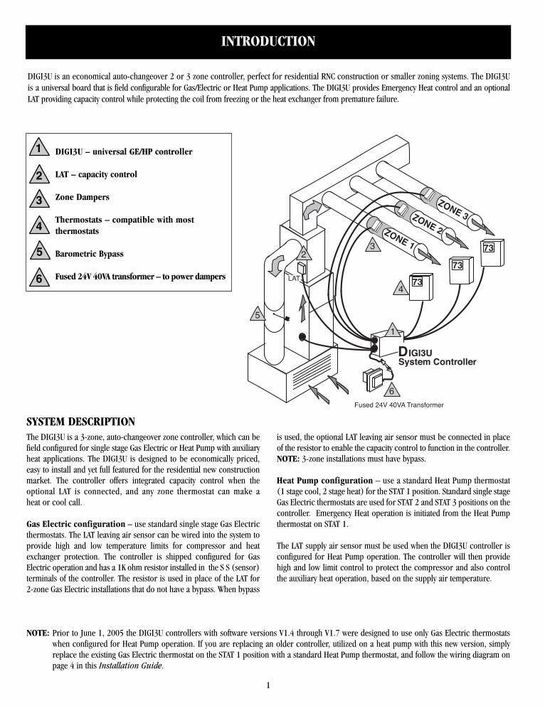
DIGI3U is an economical auto-changeover 2 or 3 zone controller, perfect for residential RNC construction or smaller zoning systems. The DIGI3Uis a universal board that is field configurable for Gas/Electric or Heat Pump applications. The DIGI3U provides Emergency Heat control and an optionalLAT providing capacity control while protecting the coil from freezing or the heat exchanger from premature failure.
INTRODUCTION
SYSTEM DESCRIPTIONThe DIGI3U is a 3-zone, auto-changeover zone controller, which can befield configured for single stage Gas Electric or Heat Pump with auxiliaryheat applications. The DIGI3U is designed to be economically priced,easy to install and yet full featured for the residential new constructionmarket. The controller offers integrated capacity control when theoptional LAT is connected, and any zone thermostat can make aheat or cool call.
Gas Electric configuration – use standard single stage Gas Electricthermostats. The LAT leaving air sensor can be wired into the system toprovide high and low temperature limits for compressor and heatexchanger protection. The controller is shipped configured for GasElectric operation and has a 1K ohm resistor installed in the S S (sensor)terminals of the controller. The resistor is used in place of the LAT for2-zone Gas Electric installations that do not have a bypass. When bypass
is used, the optional LAT leaving air sensor must be connected in placeof the resistor to enable the capacity control to function in the controller.NOTE: 3-zone installations must have bypass.
Heat Pump configuration – use a standard Heat Pump thermostat(1 stage cool, 2 stage heat) for the STAT 1 position. Standard single stageGas Electric thermostats are used for STAT 2 and STAT 3 positions on thecontroller. Emergency Heat operation is initiated from the Heat Pumpthermostat on STAT 1.
The LAT supply air sensor must be used when the DIGI3U controller isconfigured for Heat Pump operation. The controller will then providehigh and low limit control to protect the compressor and also controlthe auxiliary heat operation, based on the supply air temperature.
1
2
3
4
5
6
DIGI3U – universal GE/HP controller
LAT – capacity control
Zone Dampers
Thermostats – compatible with most thermostats
Barometric Bypass
Fused 24V 40VA transformer – to power dampers
NOTE: Prior to June 1, 2005 the DIGI3U controllers with software versions V1.4 through V1.7 were designed to use only Gas Electric thermostatswhen configured for Heat Pump operation. If you are replacing an older controller, utilized on a heat pump with this new version, simplyreplace the existing Gas Electric thermostat on the STAT 1 position with a standard Heat Pump thermostat, and follow the wiring diagram onpage 4 in this Installation Guide.
DIGI3U DESIGN INFORMATION
2
2-3 Zone Application with Bypass Damper and LAT Sensor – Usethis method if your application is for 2 or 3 zones using a bypass damperand LAT sensor. Zonex Systems recommends that all systems use abypass damper and LAT to maximize system efficiency and comfort.Ductwork design should follow typical duct design procedures: useductulator to verify airflow requirements, and follow bypass-sizingcalculations found in bypass guidelines of this manual.
2-Zone Gas/Electric Applications without a Bypass Damper orLAT Sensor – When designing a system without a bypass damper orLAT, it is necessary to oversize the ductwork and supply registers inorder to reduce noise caused by excessive static in HVAC system. Ductruns and dampers must be oversized by 70%, and supply grills mustbe increased in size to move twice the volume of air at 700 FPM; e.g.,if zone calls for 250 CFM and a 12x8 register were sized for non-zonedapplication, double the volume of air to 500 CFM, and size register for700 FPM, or a 14x8-supply register. If the Zonex Systems LAT capacitycontrol is not applied, a field supplied freeze protection and high limitdevice must be installed to protect equipment. This should only beapplied to designs in which both zones are approximately the same size.NOTE: All Heat Pump installations require the LAT sensor.
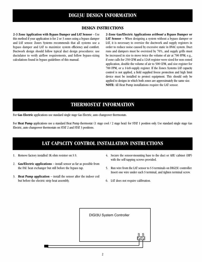
1. Remove factory installed 1K ohm resistor on S S.
2. Gas/Electric applications – install sensor as far as possible fromthe FAU heat exchanger but still before the bypass tap.
3. Heat Pump application – install the sensor after the indoor coilbut before the electric strip heat assembly.
4. Secure the sensor-mounting base to the duct or AHU cabinet (HP)with the self-tapping screws provided.
5. Run wire from the LAT sensor to S S terminals on DIGI3U controller.Insert one wire under each S terminal, and tighten terminal screw.
6. LAT does not require calibration.
DESIGN INSTRUCTIONS
THERMOSTAT INFORMATION
LAT CAPACITY CONTROL INSTALLATION INSTRUCTIONS
For Gas Electric applications use standard single stage Gas Electric, auto changeover thermostats.
For Heat Pump applications use a standard Heat Pump thermostat (1 stage cool / 2 stage heat) for STAT 1 position only. Use standard single stage GasElectric, auto changeover thermostats on STAT 2 and STAT 3 positions.
S S
DIGI3U System Controller
3
24V 40VA Transformerto Power Dampers
W-O/B
O/B
G
Y
R
C
AIRFLOWBYPASSDAMPER
ZONE 3THERMOSTAT
R Y W G C�
ZONE 2THERMOSTAT
R Y W G C ZONE 1
THERMOSTAT
R Y W G C
11
2
2
3
3TR1
TR2
R Y O/B W2 G C R Y W G C R Y W G C
R
Y
G
W-O/B
W2
C
O O O
LED
YO/B W W2 G
DPR1
DPR2
DPR3
GE
HPB
POWERSWITCH
DIGI3UA
/C U
NIT
TE
RM
INA
LS
DA
MP
ER
OU
TP
UT
S
STAT 2 STAT 3STAT 1
OPWR
CONTROL CHIP
O
O
LED
S S
JP1 JP2
W
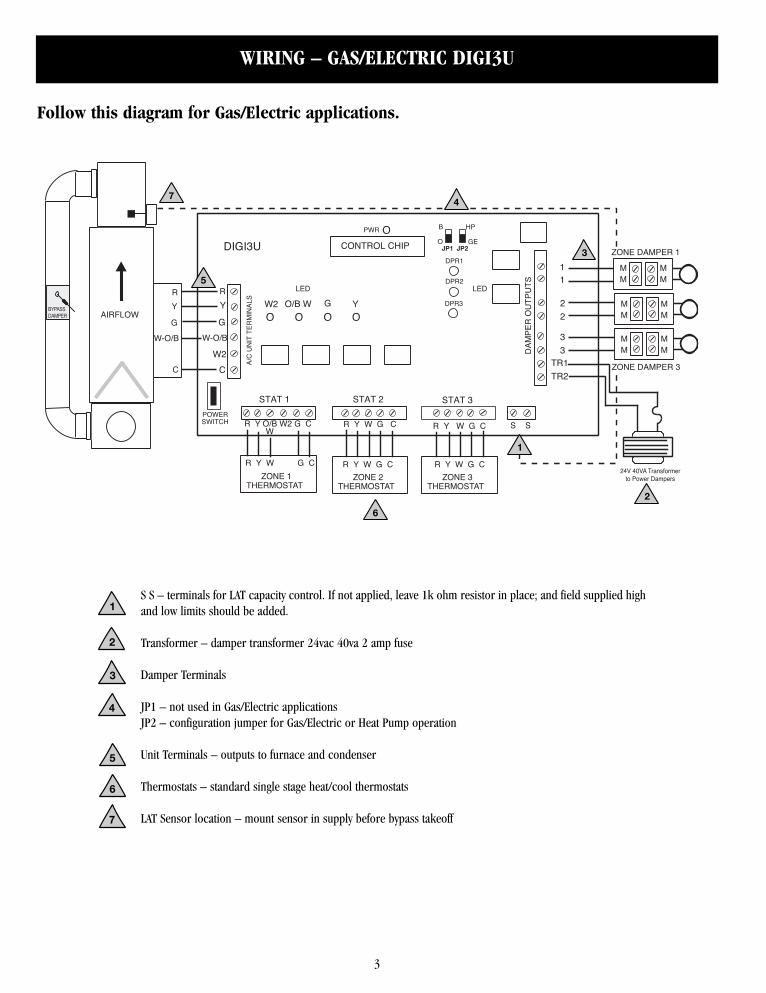
WIRING – GAS/ELECTRIC DIGI3U
S S – terminals for LAT capacity control. If not applied, leave 1k ohm resistor in place; and field supplied highand low limits should be added.
JP1 – not used in Gas/Electric applicationsJP2 – configuration jumper for Gas/Electric or Heat Pump operation
Unit Terminals – outputs to furnace and condenser
Thermostats – standard single stage heat/cool thermostats
LAT Sensor location – mount sensor in supply before bypass takeoff
1
1
2
3
4
5
6
7
2
3
4
5
6
7
Follow this diagram for Gas/Electric applications.
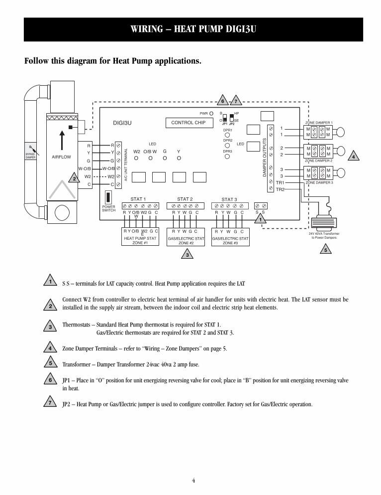
S S – terminals for LAT capacity control. Heat Pump application requires the LAT
Connect W2 from controller to electric heat terminal of air handler for units with electric heat. The LAT sensor must beinstalled in the supply air stream, between the indoor coil and electric strip heat elements.
Thermostats – Standard Heat Pump thermostat is required for STAT 1.Gas/Electric thermostats are required for STAT 2 and STAT 3.
Zone Damper Terminals – refer to “Wiring – Zone Dampers” on page 5.
JP1 – Place in “O” position for unit energizing reversing valve for cool; place in “B” position for unit energizing reversing valvein heat.
JP2 – Heat Pump or Gas/Electric jumper is used to configure controller. Factory set for Gas/Electric operation.
4
24V 40VA Transformerto Power Dampers
W-O/B
O/B
G
W2
Y
R
C
AIRFLOWBYPASSDAMPER
11
2
2
3
3
TR1
TR2
R Y O/B W2 G C R Y W G C R Y W G C
R
Y
G
W-O/B
W2
C
O O O
LED
YO/B W W2 G
DPR1
DPR2
DPR3
GE
HPB
POWERSWITCH
DIGI3UA
/C U
NIT
TE
RM
INA
L
DA
MP
ER
OU
TP
UT
S
STAT 2 STAT 3STAT 1
OPWR
CONTROL CHIP
O
O
LED
S S
JP1 JP2
W
HEAT PUMP STATZONE #1
GAS/ELECTRIC STATZONE #3
R Y W G CR Y W G CR Y O/B W2 G C
GAS/ELECTRIC STATZONE #2
E
WIRING – HEAT PUMP DIGI3U
1
1
2
3
4
5
6 7
2
3
4
5
6
7
Follow this diagram for Heat Pump applications.
5
WIRING – ZONE DAMPERS
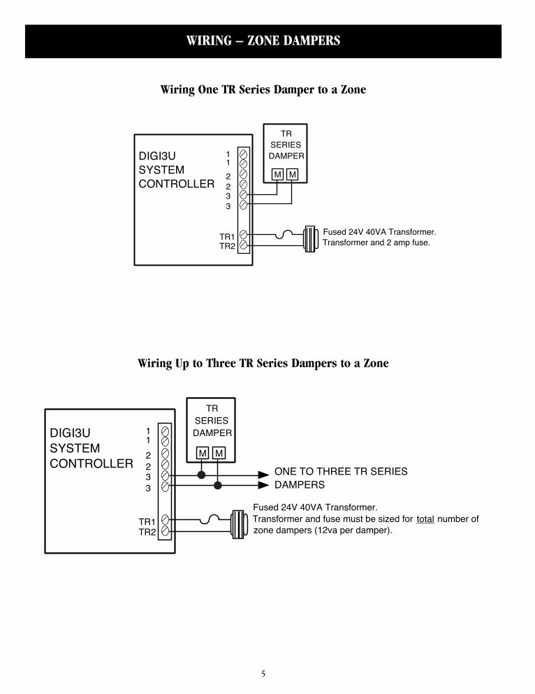
Fused 24V 40VA Transformer. Transformer and fuse must be sized for total number of zone dampers (12va per damper).
TRSERIESDAMPER
M M1
233
TR1TR2
2
1DIGI3USYSTEM CONTROLLER
ONE TO THREE TR SERIES DAMPERS
Fused 24V 40VA Transformer. Transformer and 2 amp fuse.
TRSERIESDAMPER
M M1
233
TR1TR2
2
1DIGI3USYSTEM CONTROLLER
Wiring Up to Three TR Series Dampers to a Zone
Wiring One TR Series Damper to a Zone
6
SYSTEM CONTROLLER OPERATIONS – DIGI3U
GAS/ELECTRIC OPERATION
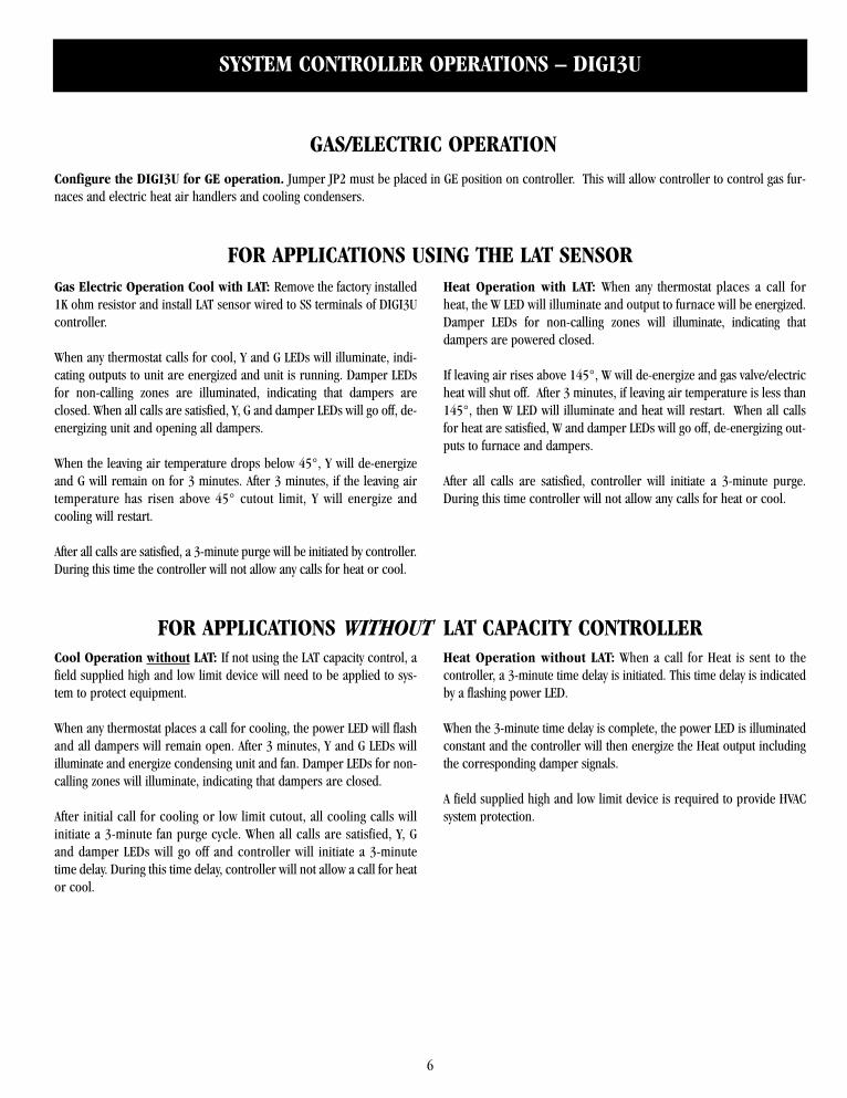
Gas Electric Operation Cool with LAT: Remove the factory installed1K ohm resistor and install LAT sensor wired to SS terminals of DIGI3Ucontroller.
When any thermostat calls for cool, Y and G LEDs will illuminate, indi-cating outputs to unit are energized and unit is running. Damper LEDsfor non-calling zones are illuminated, indicating that dampers areclosed. When all calls are satisfied, Y, G and damper LEDs will go off, de-energizing unit and opening all dampers.
When the leaving air temperature drops below 45°, Y will de-energizeand G will remain on for 3 minutes. After 3 minutes, if the leaving airtemperature has risen above 45° cutout limit, Y will energize andcooling will restart.
After all calls are satisfied, a 3-minute purge will be initiated by controller.During this time the controller will not allow any calls for heat or cool.
Heat Operation with LAT: When any thermostat places a call forheat, the W LED will illuminate and output to furnace will be energized.Damper LEDs for non-calling zones will illuminate, indicating thatdampers are powered closed.
If leaving air rises above 145°, W will de-energize and gas valve/electricheat will shut off. After 3 minutes, if leaving air temperature is less than145°, then W LED will illuminate and heat will restart. When all callsfor heat are satisfied, W and damper LEDs will go off, de-energizing out-puts to furnace and dampers.
After all calls are satisfied, controller will initiate a 3-minute purge.During this time controller will not allow any calls for heat or cool.
Cool Operation without LAT: If not using the LAT capacity control, afield supplied high and low limit device will need to be applied to sys-tem to protect equipment.
When any thermostat places a call for cooling, the power LED will flashand all dampers will remain open. After 3 minutes, Y and G LEDs willilluminate and energize condensing unit and fan. Damper LEDs for non-calling zones will illuminate, indicating that dampers are closed.
After initial call for cooling or low limit cutout, all cooling calls willinitiate a 3-minute fan purge cycle. When all calls are satisfied, Y, Gand damper LEDs will go off and controller will initiate a 3-minutetime delay. During this time delay, controller will not allow a call for heator cool.
Heat Operation without LAT: When a call for Heat is sent to thecontroller, a 3-minute time delay is initiated. This time delay is indicatedby a flashing power LED.
When the 3-minute time delay is complete, the power LED is illuminatedconstant and the controller will then energize the Heat output includingthe corresponding damper signals.
A field supplied high and low limit device is required to provide HVACsystem protection.
Configure the DIGI3U for GE operation. Jumper JP2 must be placed in GE position on controller. This will allow controller to control gas fur-naces and electric heat air handlers and cooling condensers.
FOR APPLICATIONS WITHOUT LAT CAPACITY CONTROLLER
FOR APPLICATIONS USING THE LAT SENSOR
SYSTEM CONTROLLER OPERATIONS – DIGI3U
7
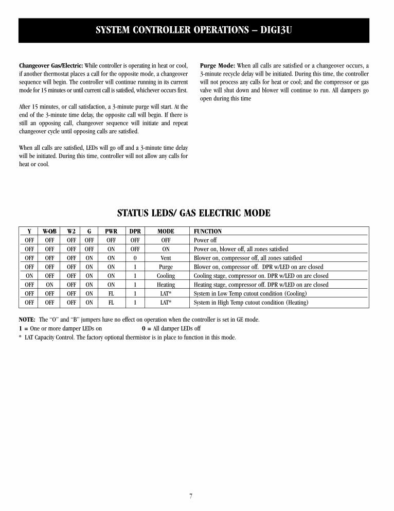
Y W-O/B W2 G PWR DPR MODE FUNCTIONOFF OFF OFF OFF OFF OFF OFF Power offOFF OFF OFF OFF ON OFF ON Power on, blower off, all zones satisfiedOFF OFF OFF ON ON 0 Vent Blower on, compressor off, all zones satisfiedOFF OFF OFF ON ON 1 Purge Blower on, compressor off. DPR w/LED on are closedON OFF OFF ON ON 1 Cooling Cooling stage, compressor on. DPR w/LED on are closed OFF ON OFF ON ON 1 Heating Heating stage, compressor off. DPR w/LED on are closedOFF OFF OFF ON FL 1 LAT* System in Low Temp cutout condition (Cooling)OFF OFF OFF ON FL 1 LAT* System in High Temp cutout condition (Heating)
STATUS LEDS/ GAS ELECTRIC MODE
NOTE: The “O” and “B” jumpers have no effect on operation when the controller is set in GE mode.1 = One or more damper LEDs on 0 = All damper LEDs off* LAT Capacity Control. The factory optional thermistor is in place to function in this mode.
Changeover Gas/Electric: While controller is operating in heat or cool,if another thermostat places a call for the opposite mode, a changeoversequence will begin. The controller will continue running in its currentmode for 15 minutes or until current call is satisfied, whichever occurs first.
After 15 minutes, or call satisfaction, a 3-minute purge will start. At theend of the 3-minute time delay, the opposite call will begin. If there isstill an opposing call, changeover sequence will initiate and repeatchangeover cycle until opposing calls are satisfied.
When all calls are satisfied, LEDs will go off and a 3-minute time delaywill be initiated. During this time, controller will not allow any calls forheat or cool.
Purge Mode: When all calls are satisfied or a changeover occurs, a3-minute recycle delay will be initiated. During this time, the controllerwill not process any calls for heat or cool; and the compressor or gasvalve will shut down and blower will continue to run. All dampers goopen during this time
8
SYSTEM CONTROLLER OPERATIONS – DIGI3U
HEAT PUMP OPERATION
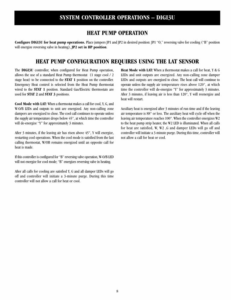
The DIGI3U controller, when configured for Heat Pump operation,allows the use of a standard Heat Pump thermostat (1 stage cool / 2stage heat) to be connected to the STAT 1 position on the controller.Emergency Heat control is selected from the Heat Pump thermostatwired to the STAT 1 position. Standard Gas/Electric thermostats areused for STAT 2 and STAT 3 positions.
Cool Mode with LAT: When a thermostat makes a call for cool, Y, G, andW-O/B LEDs and outputs to unit are energized. Any non-calling zonedampers are energized to close. The cool call continues to operate unlessthe supply air temperature drops below 45°, at which time the controllerwill de-energize “Y” for approximately 3 minutes.
After 3 minutes, if the leaving air has risen above 45°, Y will energize,restarting cool operations. When the cool mode is satisfied from the lastcalling thermostat, W/OB remains energized until an opposite call forheat is made.
If this controller is configured for “B” reversing valve operation, W-O/B LEDwill not energize for cool mode; “B” energizes reversing valve in heating.
After all calls for cooling are satisfied Y, G and all damper LEDs will gooff and controller will initiate a 3-minute purge. During this timecontroller will not allow a call for heat or cool.
Heat Mode with LAT: When a thermostat makes a call for heat, Y & GLEDs and unit outputs are energized. Any non-calling zone damperLEDs and outputs are energized to close. The heat call will continue tooperate unless the supply air temperature rises above 120°, at whichtime the controller will de-energize “Y” for approximately 3 minutes.After 3 minutes, if leaving air is less than 120°, Y will reenergize andheat will restart.
Auxiliary heat is energized after 3 minutes of run time and if the leavingair temperature is 88° or less. The auxiliary heat will cycle off when theleaving air temperature reaches 100°. When the controller energizes W2to the heat pump strip heater, the W2 LED is illuminated. When all callsfor heat are satisfied, W, W2 ,G and damper LEDs will go off andcontroller will initiate a 3-minute purge. During this time, controller willnot allow a call for heat or cool.
Configure DIGI3U for heat pump operations. Place jumpers JP1 and JP2 in desired position: JP1 “O,” reversing valve for cooling (“B” positionwill energize reversing valve in heating), JP2 set in HP position.
HEAT PUMP CONFIGURATION REQUIRES USING THE LAT SENSOR
9
SYSTEM CONTROLLER OPERATIONS – DIGI3U
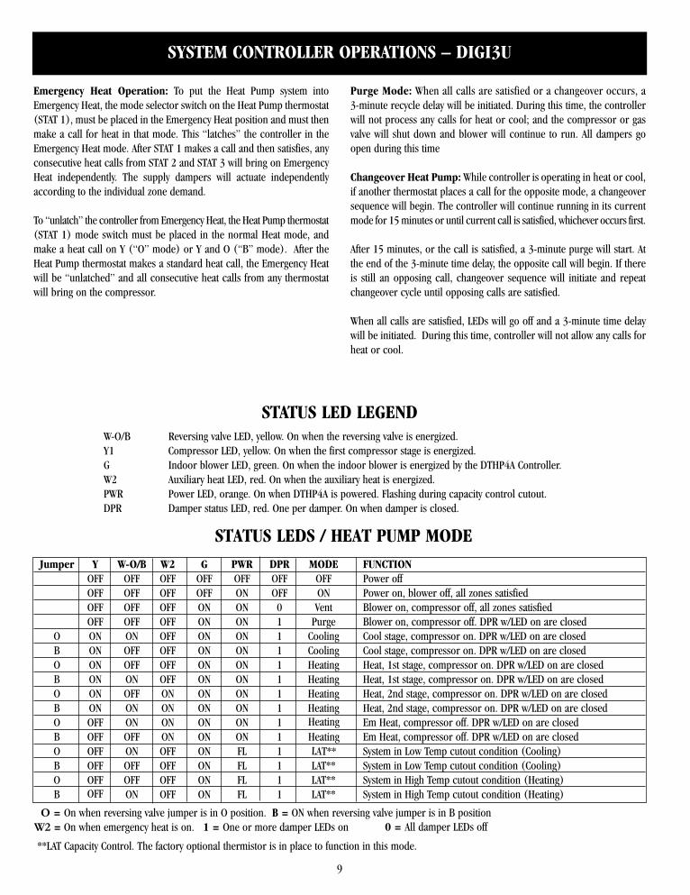
Jumper Y W-O/B W2 G PWR DPR MODE FUNCTIONOFF OFF OFF OFF OFF OFF OFF Power offOFF OFF OFF OFF ON OFF ON Power on, blower off, all zones satisfiedOFF OFF OFF ON ON 0 Vent Blower on, compressor off, all zones satisfiedOFF OFF OFF ON ON 1 Purge Blower on, compressor off. DPR w/LED on are closed
O ON ON OFF ON ON 1 Cooling Cool stage, compressor on. DPR w/LED on are closedB ON OFF OFF ON ON 1 Cooling Cool stage, compressor on. DPR w/LED on are closedO ON OFF OFF ON ON 1 Heating Heat, 1st stage, compressor on. DPR w/LED on are closedB ON ON OFF ON ON 1 Heating Heat, 1st stage, compressor on. DPR w/LED on are closedO ON OFF ON ON ON 1 Heating Heat, 2nd stage, compressor on. DPR w/LED on are closedB ON ON ON ON ON 1 Heating Heat, 2nd stage, compressor on. DPR w/LED on are closedO OFF ON ON ON ON 1 Heating Em Heat, compressor off. DPR w/LED on are closedB OFF OFF ON ON ON 1 Heating Em Heat, compressor off. DPR w/LED on are closedO OFF ON OFF ON FL 1 LAT** System in Low Temp cutout condition (Cooling)B OFF OFF OFF ON FL 1 LAT** System in Low Temp cutout condition (Cooling)O OFF OFF OFF ON FL 1 LAT** System in High Temp cutout condition (Heating)B OFF ON OFF ON FL 1 LAT** System in High Temp cutout condition (Heating)
O = On when reversing valve jumper is in O position. B = ON when reversing valve jumper is in B positionW2 = On when emergency heat is on. 1 = One or more damper LEDs on 0 = All damper LEDs off
**LAT Capacity Control. The factory optional thermistor is in place to function in this mode.
STATUS LED LEGENDW-O/B Reversing valve LED, yellow. On when the reversing valve is energized.Y1 Compressor LED, yellow. On when the first compressor stage is energized.G Indoor blower LED, green. On when the indoor blower is energized by the DTHP4A Controller.W2 Auxiliary heat LED, red. On when the auxiliary heat is energized.PWR Power LED, orange. On when DTHP4A is powered. Flashing during capacity control cutout.DPR Damper status LED, red. One per damper. On when damper is closed.
Emergency Heat Operation: To put the Heat Pump system intoEmergency Heat, the mode selector switch on the Heat Pump thermostat(STAT 1), must be placed in the Emergency Heat position and must thenmake a call for heat in that mode. This “latches” the controller in theEmergency Heat mode. After STAT 1 makes a call and then satisfies, anyconsecutive heat calls from STAT 2 and STAT 3 will bring on EmergencyHeat independently. The supply dampers will actuate independentlyaccording to the individual zone demand.
To “unlatch” the controller from Emergency Heat, the Heat Pump thermostat(STAT 1) mode switch must be placed in the normal Heat mode, andmake a heat call on Y (“O” mode) or Y and O (“B” mode). After theHeat Pump thermostat makes a standard heat call, the Emergency Heatwill be “unlatched” and all consecutive heat calls from any thermostatwill bring on the compressor.
Purge Mode: When all calls are satisfied or a changeover occurs, a3-minute recycle delay will be initiated. During this time, the controllerwill not process any calls for heat or cool; and the compressor or gasvalve will shut down and blower will continue to run. All dampers goopen during this time
Changeover Heat Pump: While controller is operating in heat or cool,if another thermostat places a call for the opposite mode, a changeoversequence will begin. The controller will continue running in its currentmode for 15 minutes or until current call is satisfied, whichever occurs first.
After 15 minutes, or the call is satisfied, a 3-minute purge will start. Atthe end of the 3-minute time delay, the opposite call will begin. If thereis still an opposing call, changeover sequence will initiate and repeatchangeover cycle until opposing calls are satisfied.
When all calls are satisfied, LEDs will go off and a 3-minute time delaywill be initiated. During this time, controller will not allow any calls forheat or cool.
STATUS LEDS / HEAT PUMP MODE
10
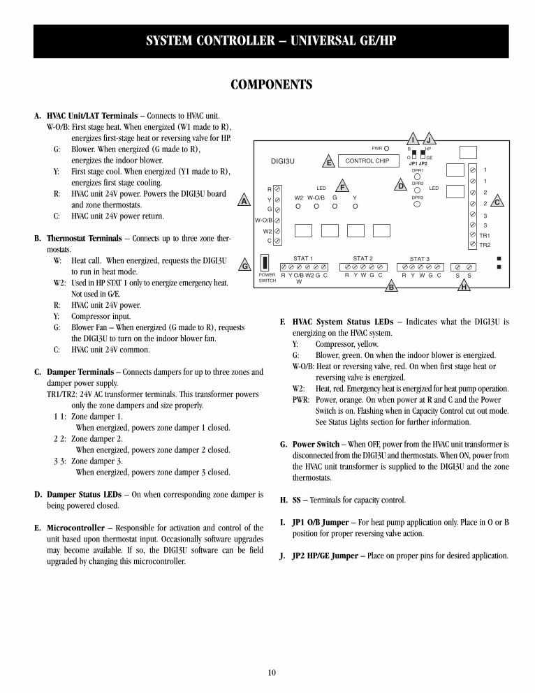
W-O/B: First stage heat. When energized (W1 made to R), energizes first-stage heat or reversing valve for HP.
G: Blower. When energized (G made to R), energizes the indoor blower.
Y: First stage cool. When energized (Y1 made to R), energizes first stage cooling.
R: HVAC unit 24V power. Powers the DIGI3U board and zone thermostats.
C: HVAC unit 24V power return.
B. Thermostat Terminals – Connects up to three zone ther-mostats.
W: Heat call. When energized, requests the DIGI3U to run in heat mode.
W2: Used in HP STAT 1 only to energize emergency heat. Not used in G/E.
R: HVAC unit 24V power. Y: Compressor input.G: Blower Fan – When energized (G made to R), requests
the DIGI3U to turn on the indoor blower fan.C: HVAC unit 24V common.
C. Damper Terminals – Connects dampers for up to three zones anddamper power supply.TR1/TR2: 24V AC transformer terminals. This transformer powers
only the zone dampers and size properly.1 1: Zone damper 1.
When energized, powers zone damper 1 closed.2 2: Zone damper 2.
When energized, powers zone damper 2 closed.3 3: Zone damper 3.
When energized, powers zone damper 3 closed.
D. Damper Status LEDs – On when corresponding zone damper isbeing powered closed.
E. Microcontroller – Responsible for activation and control of theunit based upon thermostat input. Occasionally software upgradesmay become available. If so, the DIGI3U software can be fieldupgraded by changing this microcontroller.
F. HVAC System Status LEDs – Indicates what the DIGI3U isenergizing on the HVAC system.Y: Compressor, yellow.G: Blower, green. On when the indoor blower is energized.W-O/B: Heat or reversing valve, red. On when first stage heat or
reversing valve is energized.W2: Heat, red. Emergency heat is energized for heat pump operation.PWR: Power, orange. On when power at R and C and the Power
Switch is on. Flashing when in Capacity Control cut out mode.See Status Lights section for further information.
G. Power Switch – When OFF, power from the HVAC unit transformer isdisconnected from the DIGI3U and thermostats. When ON, power fromthe HVAC unit transformer is supplied to the DIGI3U and the zonethermostats.
H. SS – Terminals for capacity control.
I. JP1 O/B Jumper – For heat pump application only. Place in O or Bposition for proper reversing valve action.
J. JP2 HP/GE Jumper – Place on proper pins for desired application.
SYSTEM CONTROLLER – UNIVERSAL GE/HP
1
1
2
2
3
3
TR1
TR2
o o o o
R Y O/B W2 G C R Y W G C R Y W G C S
R
Y
G
W-O/B
W2
C
O O O
LED
YW-O/B W2 G
DPR1
DPR2
DPR3
GE
HPB
POWERSWITCH
DIGI3U
STAT 2 STAT 3STAT 1
OPWR
CONTROL CHIP
O
O
LED
S
A
B
J
G
H
I
F
E
D
C
JP2JP1
W
COMPONENTS
A. HVAC Unit/LAT Terminals – Connects to HVAC unit.
11
ZONE DAMPERS
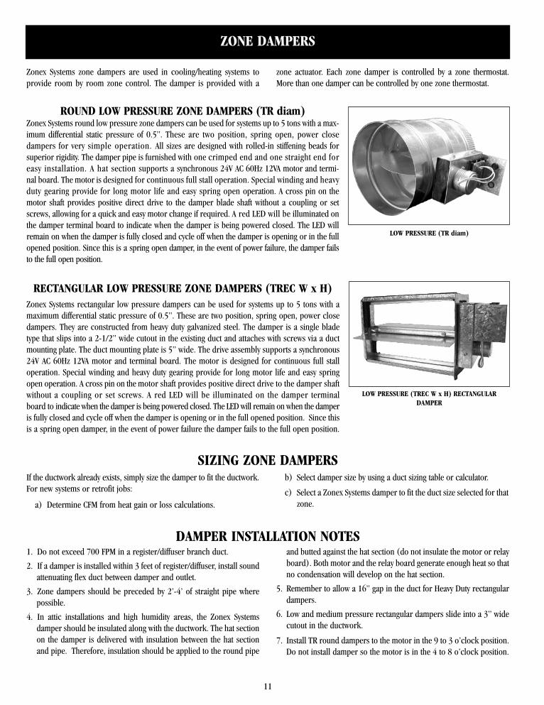
RECTANGULAR LOW PRESSURE ZONE DAMPERS (TREC W x H)Zonex Systems rectangular low pressure dampers can be used for systems up to 5 tons with amaximum differential static pressure of 0.5”. These are two position, spring open, power closedampers. They are constructed from heavy duty galvanized steel. The damper is a single bladetype that slips into a 2-1/2” wide cutout in the existing duct and attaches with screws via a ductmounting plate. The duct mounting plate is 5” wide. The drive assembly supports a synchronous24V AC 60Hz 12VA motor and terminal board. The motor is designed for continuous full stalloperation. Special winding and heavy duty gearing provide for long motor life and easy springopen operation. A cross pin on the motor shaft provides positive direct drive to the damper shaftwithout a coupling or set screws. A red LED will be illuminated on the damper terminalboard to indicate when the damper is being powered closed. The LED will remain on when the damperis fully closed and cycle off when the damper is opening or in the full opened position. Since thisis a spring open damper, in the event of power failure the damper fails to the full open position.
LOW PRESSURE (TREC W x H) RECTANGULARDAMPER
Zonex Systems zone dampers are used in cooling/heating systems toprovide room by room zone control. The damper is provided with a
zone actuator. Each zone damper is controlled by a zone thermostat.More than one damper can be controlled by one zone thermostat.
ROUND LOW PRESSURE ZONE DAMPERS (TR diam)Zonex Systems round low pressure zone dampers can be used for systems up to 5 tons with a max-imum differential static pressure of 0.5”. These are two position, spring open, power closedampers for very simple operation. All sizes are designed with rolled-in stiffening beads forsuperior rigidity. The damper pipe is furnished with one crimped end and one straight end foreasy installation. A hat section supports a synchronous 24V AC 60Hz 12VA motor and termi-nal board. The motor is designed for continuous full stall operation. Special winding and heavyduty gearing provide for long motor life and easy spring open operation. A cross pin on themotor shaft provides positive direct drive to the damper blade shaft without a coupling or setscrews, allowing for a quick and easy motor change if required. A red LED will be illuminated onthe damper terminal board to indicate when the damper is being powered closed. The LED willremain on when the damper is fully closed and cycle off when the damper is opening or in the fullopened position. Since this is a spring open damper, in the event of power failure, the damper failsto the full open position.
LOW PRESSURE (TR diam)
SIZING ZONE DAMPERSIf the ductwork already exists, simply size the damper to fit the ductwork.For new systems or retrofit jobs:
a) Determine CFM from heat gain or loss calculations.
b) Select damper size by using a duct sizing table or calculator.
c) Select a Zonex Systems damper to fit the duct size selected for thatzone.
DAMPER INSTALLATION NOTES1. Do not exceed 700 FPM in a register/diffuser branch duct.
2. If a damper is installed within 3 feet of register/diffuser, install soundattenuating flex duct between damper and outlet.
3. Zone dampers should be preceded by 2’-4’ of straight pipe wherepossible.
4. In attic installations and high humidity areas, the Zonex Systemsdamper should be insulated along with the ductwork. The hat sectionon the damper is delivered with insulation between the hat sectionand pipe. Therefore, insulation should be applied to the round pipe
and butted against the hat section (do not insulate the motor or relayboard). Both motor and the relay board generate enough heat so thatno condensation will develop on the hat section.
5. Remember to allow a 16” gap in the duct for Heavy Duty rectangulardampers.
6. Low and medium pressure rectangular dampers slide into a 3” widecutout in the ductwork.
7. Install TR round dampers to the motor in the 9 to 3 o’clock position.Do not install damper so the motor is in the 4 to 8 o’clock position.
12
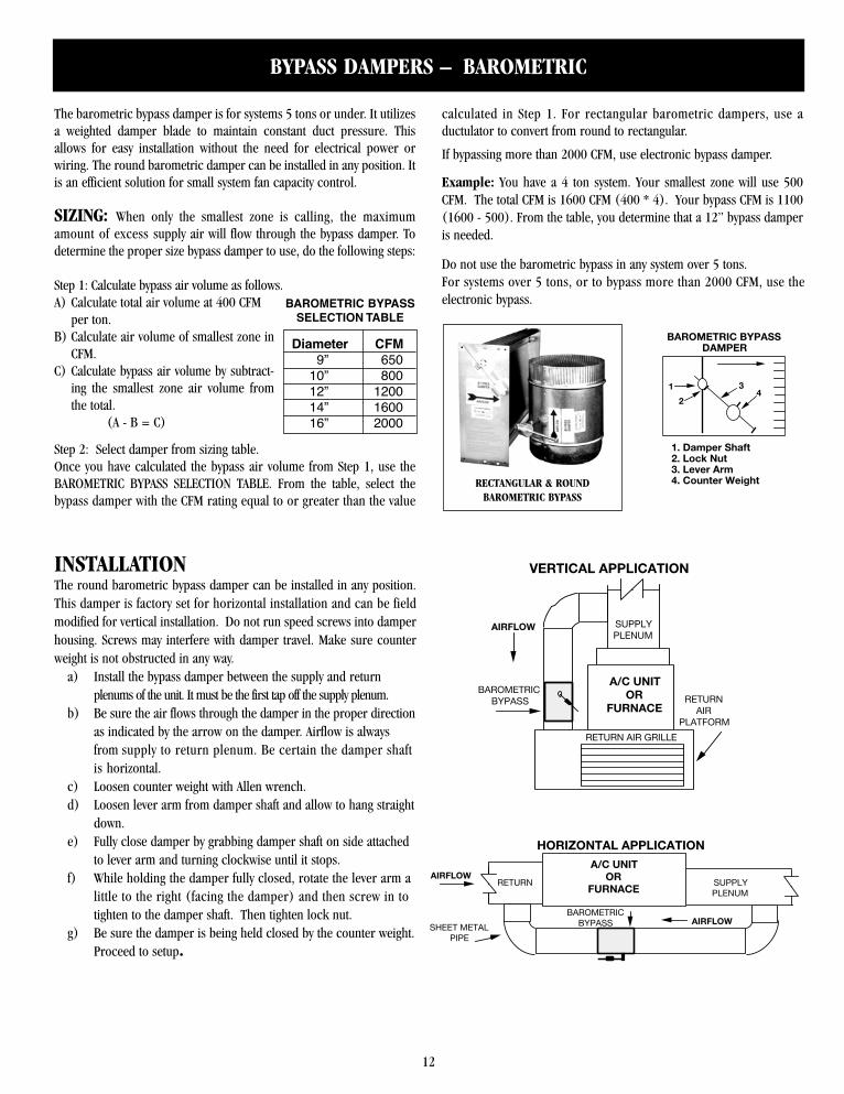
The barometric bypass damper is for systems 5 tons or under. It utilizesa weighted damper blade to maintain constant duct pressure. Thisallows for easy installation without the need for electrical power orwiring. The round barometric damper can be installed in any position. Itis an efficient solution for small system fan capacity control.
SIZING: When only the smallest zone is calling, the maximumamount of excess supply air will flow through the bypass damper. Todetermine the proper size bypass damper to use, do the following steps:
Step 1: Calculate bypass air volume as follows.A) Calculate total air volume at 400 CFM
per ton.B) Calculate air volume of smallest zone in
CFM.C) Calculate bypass air volume by subtract-
ing the smallest zone air volume fromthe total.
(A - B = C)
Step 2: Select damper from sizing table.Once you have calculated the bypass air volume from Step 1, use theBAROMETRIC BYPASS SELECTION TABLE. From the table, select thebypass damper with the CFM rating equal to or greater than the value
calculated in Step 1. For rectangular barometric dampers, use aductulator to convert from round to rectangular.
If bypassing more than 2000 CFM, use electronic bypass damper.
Example: You have a 4 ton system. Your smallest zone will use 500CFM. The total CFM is 1600 CFM (400 * 4). Your bypass CFM is 1100(1600 - 500). From the table, you determine that a 12” bypass damperis needed.
Do not use the barometric bypass in any system over 5 tons.For systems over 5 tons, or to bypass more than 2000 CFM, use theelectronic bypass.
RECTANGULAR & ROUNDBAROMETRIC BYPASS
BYPASS DAMPERS – BAROMETRIC
AIRFLOW1
24
3
1. Damper Shaft2. Lock Nut3. Lever Arm4. Counter Weight
BAROMETRIC BYPASSDAMPERDiameter CFM
9” 65010” 80012” 120014” 160016” 2000
BAROMETRIC BYPASSSELECTION TABLE
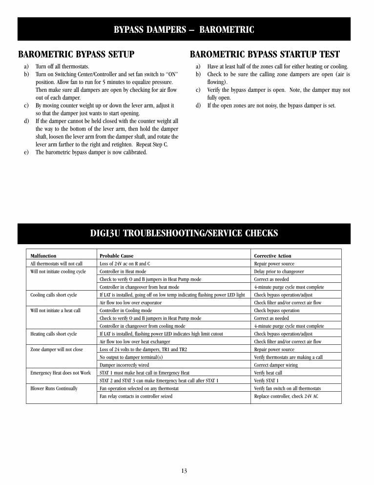
INSTALLATIONThe round barometric bypass damper can be installed in any position.This damper is factory set for horizontal installation and can be fieldmodified for vertical installation. Do not run speed screws into damperhousing. Screws may interfere with damper travel. Make sure counterweight is not obstructed in any way.
a) Install the bypass damper between the supply and returnplenums of the unit. It must be the first tap off the supply plenum.
b) Be sure the air flows through the damper in the proper directionas indicated by the arrow on the damper. Airflow is alwaysfrom supply to return plenum. Be certain the damper shaftis horizontal.
c) Loosen counter weight with Allen wrench.d) Loosen lever arm from damper shaft and allow to hang straight
down.e) Fully close damper by grabbing damper shaft on side attached
to lever arm and turning clockwise until it stops.f) While holding the damper fully closed, rotate the lever arm a
little to the right (facing the damper) and then screw in totighten to the damper shaft. Then tighten lock nut.
g) Be sure the damper is being held closed by the counter weight.Proceed to setup.
AIRFLOW
AIRFLOW
RETURN
BAROMETRIC BYPASS
HORIZONTAL APPLICATION
SHEET METALPIPE
SUPPLYPLENUM
A/C UNITOR
FURNACE
A/C UNITOR
FURNACERETURN
AIR PLATFORM
BAROMETRICBYPASS
RETURN AIR GRILLE
AIRFLOW SUPPLYPLENUM
VERTICAL APPLICATION
13
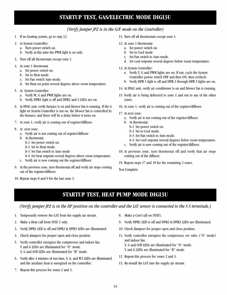
DIGI3U TROUBLESHOOTING/SERVICE CHECKS
Malfunction Probable Cause Corrective Action
All thermostats will not call Loss of 24V ac on R and C Repair power source
Will not initiate cooling cycle Controller in Heat mode Delay prior to changeover
Check to verify O and B jumpers in Heat Pump mode Correct as needed
Controller in changeover from heat mode 4-minute purge cycle must complete
Cooling calls short cycle If LAT is installed, going off on low temp indicating flashing power LED light Check bypass operation/adjust
Air flow too low over evaporator Check filter and/or correct air flow
Will not initiate a heat call Controller in Cooling mode Check bypass operation
Check to verify O and B jumpers in Heat Pump mode Correct as needed
Controller in changeover from cooling mode 4-minute purge cycle must complete
Heating calls short cycle If LAT is installed, flashing power LED indicates high limit cutout Check bypass operation/adjust
Air flow too low over heat exchanger Check filter and/or correct air flow
Zone damper will not close Loss of 24 volts to the dampers, TR1 and TR2 Repair power source
No output to damper terminal(s) Verify thermostats are making a call
Damper incorrectly wired Correct damper wiring
Emergency Heat does not Work STAT 1 must make heat call in Emergency Heat Verify heat call
STAT 2 and STAT 3 can make Emergency heat call after STAT 1 Verify STAT 1
Blower Runs Continually Fan operation selected on any thermostat Verify fan switch on all thermostats
Fan relay contacts in controller seized Replace controller, check 24V AC
BAROMETRIC BYPASS SETUPa) Turn off all thermostats.b) Turn on Switching Center/Controller and set fan switch to “ON”
position. Allow fan to run for 5 minutes to equalize pressure.Then make sure all dampers are open by checking for air flowout of each damper.
c) By moving counter weight up or down the lever arm, adjust itso that the damper just wants to start opening.
d) If the damper cannot be held closed with the counter weight allthe way to the bottom of the lever arm, then hold the dampershaft, loosen the lever arm from the damper shaft, and rotate thelever arm farther to the right and retighten. Repeat Step C.
e) The barometric bypass damper is now calibrated.
BAROMETRIC BYPASS STARTUP TESTa) Have at least half of the zones call for either heating or cooling.b) Check to be sure the calling zone dampers are open (air is
flowing).c) Verify the bypass damper is open. Note, the damper may not
fully open.d) If the open zones are not noisy, the bypass damper is set.
BYPASS DAMPERS – BAROMETRIC
14
1. If no heating system, go to step 12.
2. At System Controller:a. Turn power switch on.b. Verify at this time the PWR light is on only.
3. Turn off all thermostats except zone 1.
4. At zone 1 thermostata. Set power switch on.b. Set to Heat mode.c. Set Fan switch Auto mode.d. Set Heat set point several degrees above room temperature.
5. At System Controller:a. Verify W, G and PWR lights are on.b. Verify DPR1 light is off and DPR2 and 3 LEDs are on.
6. At HVAC unit, verify furnace is on and blower fan is running. If the Glight on System Controller is not on, the blower fan is controlled bythe furnace; and there will be a delay before it turns on.
7. At zone 1, verify air is coming out of register/diffuser.
8. At next zone:a. Verify air is not coming out of register/diffuserb. At thermostat:
b-1 Set power switch on.b-2 Set to Heat mode.b-3 Set Fan switch to Auto modeb-4 Set heat setpoint several degrees above room temperature.
c. Verify air is now coming out the register/diffuser.
9. At the previous zone, turn thermostat off and verify air stops comingout of the register/diffuser.
10. Repeat steps 8 and 9 for the last zone 3.
11. Turn off all thermostats except zone 1.
12. At zone 1 thermostat:a. Set power switch on.b. Set to Cool modec. Set Fan switch to Auto mode.d. Set cool setpoint several degrees below room temperature.
13. At System Controller:a. Verify Y, G and PWR lights are on. If not, cycle the System
Controller power switch OFF and then ON; then recheck.b. Verify DPR 1 light is off and DPR 2 through DPR 3 lights are on.
14. At HVAC unit, verify air conditioner is on and blower fan is running.
15. Verify air is being delivered to zone 1 and not to any of the otherzones.
16. At zone 1, verify air is coming out of the register/diffuser.
17. At next zone:a. Verify air is not coming out of the register/diffuser.b. At thermostat:
b-1 Set power switch on.b-2 Set to Cool mode.b-3 Set Fan switch to Auto mode.b-4 Set cool setpoint several degrees below room temperature.
c. Verify air is now coming out of the register/diffuser.
18. At previous zone, turn thermostat off and verify that air stopscoming out of the diffuser.
19. Repeat steps 17 and 18 for the remaining 2 zones.
Test Complete.
STARTUP TEST, GAS/ELECTRIC MODE DIGI3U
(Verify Jumper JP2 is in the G/E mode on the Controller)
2. Make a Heat call from STAT 1 only.
3. Verify DPR1 LED is off and DPR2 & DPR3 LEDs are illuminated.
4. Check dampers for proper open and close position.
5. Verify controller energizes the compressor and indoor fan.Y and G LEDs are illuminated for “O” mode.Y, G and O/B LEDs are illuminated for “B” mode.
6. Verify after 4 minutes of run time, Y, G, and W2 LEDs are illuminatedand the auxiliary heat is energized on the controller.
7. Repeat this process for zones 2 and 3.
8. Make a Cool call on STAT1.
9. Verify DPR1 LED is off and DPR2 & DPR3 LEDs are illuminated.
10. Check dampers for proper open and close position.
11. Verify controller energizes the compressor, rev valve (“O” mode)and indoor fan.Y, G and O/B LEDs are illuminated for “O” mode.Y and G LEDs are illuminated for “B” mode.
12. Repeat this process for zones 2 and 3.
STARTUP TEST, HEAT PUMP MODE DIGI3U
(Verify jumper JP2 is in the HP position on the controller and the LAT sensor is connected to the S S terminals.)
1. Temporarily remove the LAT from the supply air stream.
13. Re-install the LAT into the supply air stream.
DIGI3UThree-Zone, UniversalController forGas/Electric or HeatPump Applications
Hot Line: (800) 228-2966
5622 Engineer Drive
Huntington Beach, CA 92649
Factory: (714) 898-9963 • Fax: (714) 898-6802
Visit our Web Site http://www.zonexsystems.com
PATENTED PRODUCTZonex Systems reserves the right to discontinue, or change at any time,specifications or designs without notice and without incurring obligations.Copyright 2008 by Zonex Systems
ZoningQuick Quote Web site:
www.zonexcontrols.comThe easy way to Get Quotes fast