Digidesign Inc. 3401-A Hillview Avenue Palo Alto, CA 94304 USA tel: 650·842·7900 fax: 650·842·7999 Technical Support (USA) 650·842·6699 650·856·4275 Product Information (USA) 650·842·6602 800·333·2137 Fax on Demand (USA) 1-888-USE-DIGI (873-3444) World Wide Web www.digidesign.com Digidesign FTP Site ftp.digidesign.com Pro Tools DigiRack Plug-Ins Guide Version 5.0.1 for Macintosh and Windows
Transcript
Pro ToolsDigiRack Plug-Ins Guide
Version 5.0.1 for Macintosh and Windows
Digidesign Inc.3401-A Hillview Avenue
Palo Alto, CA 94304 USAtel: 650·842·7900fax: 650·842·7999
DIGIDESIGN, AVID and PRO TOOLS are trademarks or registered trademarks of Digidesign and/or Avid Technology, Inc. All other trademarks are the property of their respective owners.
All features and specifications subject to change without notice.
Plug-Ins are special-purpose software that add additional signal processing function-ality to Pro Tools.
The DigiRack plug-ins included with Pro Tools provide a comprehensive set of digital signal processing effects that in-clude EQ, dynamics, delay, and other es-sential functions.
Plug-ins come in three formats: • TDM plug-ins (real-time)• RTAS plug-ins (real-time)• AudioSuite plug-ins (non-real-time, file-
based processing)
TDM Plug-Ins(TDM Systems only)
TDM plug-ins function as track inserts, are applied to audio during playback, and pro-cess audio non-destructively in real time. TDM plug-ins are designed for use on TDM-based Pro Tools systems, and rely on the processing power of Digidesign DSP cards. The number and variety of TDM plug-ins that you can use simultaneously in a session are limited only by the amount of DSP available. You can increase available DSP by installing additional MIX Farm or
DSP Farm cards in your computer. This power-on-demand aspect is a significant advantage of TDM-based systems.
RTAS Plug-Ins (Pro Tools LE Systems only)
RTAS (Real-Time AudioSuite) plug-ins pro-vide features and functionality similar to their TDM counterparts, but are designed for use on non-TDM-based Pro Tools sys-tems running Pro Tools LE software. Unlike TDM plug-ins, they rely on and are limited by the processing power of your computer. The more powerful your computer, the greater the number and variety of RTAS plug-ins that you can use simultaneously. Because of this dependence on the CPU or host processing, the more RTAS plug-ins you use concurrently in a session, the greater the impact on other aspects of system per-formance such as available track count, edit density, and automation latency.
Chapter 1: Getting Started with Plug-Ins 1
2
AudioSuite Plug-Ins Non-real-time AudioSuite plug-ins are not used during playback, but are instead used to process audio files on disk, creating new, rewritten audio files with the effect perma-nently applied. AudioSuite plug-ins can be used on all Pro Tools systems.
DSP Usage of Real-Time TDM Plug-InsEach real-time TDM plug-in in a Pro Tools session uses a portion of your system’s total available DSP resources. Since these DSP re-sources reside on the cards that make up your particular Pro Tools hardware config-uration, the amount of DSP available de-pends entirely on the number and type of DSP cards in your system.
The tables in Appendix A of this Guide list the total number of instances of each Digi-Rack TDM plug-in that can be powered by a single DSP chip on the two types of Digide-sign TDM-based DSP cards (the Pro Tools 24 MIX card and the DSP Farm). DSP usage differs according to card type.
✽ The Show DSP Usage window (in the Pro Tools Windows menu) allows you to see ex-actly how much DSP is available on your sys-tem and how it is currently being used. For details, see the Pro Tools Reference Guide.
DigiRack Plug-Ins Guide
DSP Manager Allows DSP Sharing Between TDM Plug-InsDigidesign’s MultiShell and DSP Manager technologies allow up to five different types of TDM plug-ins to share the same DSP chip at one time. This allows you to simultaneously use a greater variety of plug-ins by efficiently managing the DSP available on each chip in your system.
In order to take advantage of this capabil-ity, plug-ins must be MultiShell compati-ble. The Dynamics II, EQ II, and Dither DigiRack TDM plug-ins are all MultiShell compatible.
If you are not sure whether a specific Third-Party plug-in is MultiShell-compatible, please check with its developer.
Allocating Additional Memory to DAE(Macintosh Only)
If you plan to use a large number of plug-ins in addition to the DigiRack plug-ins in-cluded with Pro Tools, allocating addi-tional memory to DAE will help ensure re-liable system performance.
If enough RAM is available in your com-puter, allocate 1-2 megabytes of additional RAM to DAE for each non-DigiRack plug-in installed on your system.
To allocate additional memory to DAE:
1 Start Pro Tools so that DAE can calculate its basic memory allocation.
2 Go to the Finder, and under the Apple menu, choose About This Computer.
3 If you have 3 megabytes or more of mem-ory available (as indicated in the Largest Unused Block portion of this window), go to step 4. If you have less than 3 megabytes of free memory (3,000k), stop here: Do not allocate additional memory to DAE unless you install additional RAM in your com-puter.
4 Quit Pro Tools.
5 Open the DAE folder inside your System Folder, select DAE, and choose Get Info from the Finder’s File menu.
6 Enter the desired amount of memory above the minimum requirement in the Pre-ferred Size field. For example, if the Pre-ferred Size field currently says “9402k” and you wish to allocate an additional 3 mega-bytes of memory (1 megabyte equals 1024 kilobytes), enter “12474” into the Preferred Size field.
7 Close the Get Info dialog.
8 The next time you start Pro Tools, DAE will use this new memory allocation.
Allocating additional memory to DAE
Chapter 1: Getting Started with Plug-Ins 3
4
DigiRack Plug-Ins Guide
chapter 2
Working with Real-Time Plug-Ins
Real-time plug-ins process audio non-de-structively in real time. They do not alter the original source audio, but only apply their effect during playback.
There are two formats of real-time plug-ins, TDM plug-ins and RTAS plug-ins. TDM plug-ins are designed for use on TDM-equipped Pro Tools systems. RTAS plug-ins are designed for use with Pro Tools LE soft-ware.
Plug-Ins as InsertsReal-time plug-ins are available as track in-serts and must be inserted in-line on an audio track, auxiliary return, or a master fader. A maximum of 5 real-time plug-ins can be used per track.
When more than one insert is used on a track, they process the audio in series, each effect being added to the previous one, from top to bottom in the Mix window.
Pre-Fader Insert OperationReal-time plug-ins function as pre-fader in-serts, meaning that their level is not af-fected by a track’s volume fader (except when used on a master fader). For this rea-
son, clipping can occur if you boost the gain of a plug-in to extremes. This is partic-ularly true on tracks recorded at high am-plitude. Listen carefully to your tracks and watch on-screen metering to identify and rectify clipping if it occurs.
Mono and Stereo Inserts
Most plug-ins can be used in either mono or stereo, and some feature mono-to-stereo capability for creating a stereo image from a mono track. Some stereo plug-ins require up to twice as much processing power as mono plug-ins. Any inserts that occur on a track after another stereo insert are auto-matically used in stereo.
Processing Power Requirements of TDM and RTAS Plug-InsTDM and RTAS plug-ins differ in their pro-cessing power requirements. TDM plug-ins use DSP power. RTAS plug-ins use CPU power.
Chapter 2: Working with Real-Time Plug-Ins 5
6
TDM Plug-Ins and DSP PowerThe number and variety of TDM plug-ins you can use at one time depends on how much DSP power is available in your sys-tem. Since the TDM hardware on Pro Tools 24 and Pro Tool 24 MIX cards provide dedicated DSP power on demand for plug-ins, plug-in performance isn’t lim-ited by CPU processing power.
You can add more mixing and processing power to your system by installing addi-tional DSP cards, provided you have un-used PCI expansion slots in your computer or use a Digidesign-approved Expansion Chassis.
The DSP Usage window (Windows > Show DSP Usage) shows how much DSP is avail-able in your system and how it is currently being used.
☞ For more information about DSP usage and allocation, see Appendix A of this Guide and also Appendix A of the Pro Tools Reference Guide.
RTAS Plug-Ins and CPU PowerBecause RTAS plug-ins rely on and are lim-ited by the processing power of your com-puter’s CPU, the more RTAS plug-ins you use concurrently in a session, the greater
The DSP Usage window
DigiRack Plug-Ins Guide
the impact on other aspects of your sys-tem’s performance such as maximum track count, the density of edits possible, and la-tency in automation and recording.
The CPU Load meter in the Automation Enable window (Windows > Show Automa-tion/Performance) shows how much of your computer’s processing power is cur-rently being used, and how much is still available.
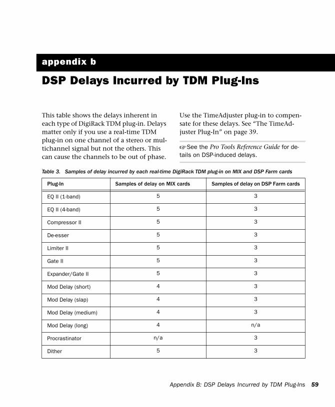
Delay in Digital Signal Processing(TDM Plug-Ins Only)
DSP processing in digital audio systems in-curs signal delay of varying amounts. Such delays can vary from as short as several mi-croseconds to as long as several millisec-onds, depending on the type of processing applied.
Delays are a matter of concern only if you use a real-time TDM plug-in on one chan-nel of a stereo or multichannel signal but not the others. This can cause the channels to be slightly out of phase. If you are work-
CPU Load meter
ing with mono tracks, or are processing all channels with the same plug-ins, these sig-nal delays should not be a matter of con-cern.
None of the current DigiRack RTAS plug-ins incur signal delays of this type.
☞ See Appendix B of this Guide for informa-tion on delays inherent in specific DigiRack TDM plug-ins. See also Appendix A of the Pro Tools Reference Guide for a comprehensive guide to calculating DSP-induced delays.
Compensating with TimeAdjuster
You can compensate for TDM plug-in-in-duced delays by using the TimeAdjuster plug-in. This plug-in allows you to apply a specific number of samples of delay to the signal path of a Pro Tools track. TimeAd-juster provides several settings files that ap-ply the correct compensation time in sam-ples for delay introduced by one or more plug-ins. See “The TimeAdjuster Plug-In” on page 39.
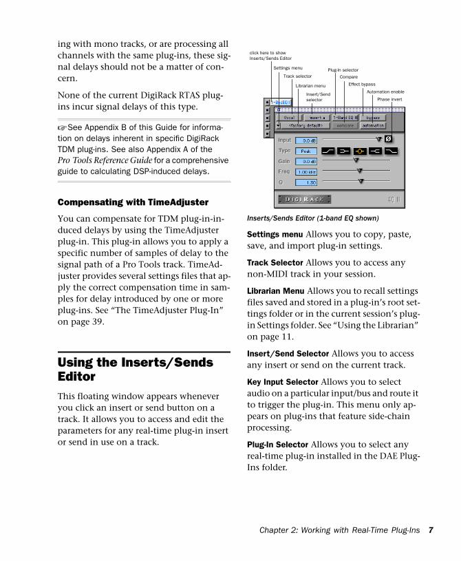
Using the Inserts/Sends EditorThis floating window appears whenever you click an insert or send button on a track. It allows you to access and edit the parameters for any real-time plug-in insert or send in use on a track.
Settings menu Allows you to copy, paste, save, and import plug-in settings.
Track Selector Allows you to access any non-MIDI track in your session.
Librarian Menu Allows you to recall settings files saved and stored in a plug-in’s root set-tings folder or in the current session’s plug-in Settings folder. See “Using the Librarian” on page 11.
Insert/Send Selector Allows you to access any insert or send on the current track.
Key Input Selector Allows you to select audio on a particular input/bus and route it to trigger the plug-in. This menu only ap-pears on plug-ins that feature side-chain processing.
Plug-In Selector Allows you to select any real-time plug-in installed in the DAE Plug-Ins folder.
Inserts/Sends Editor (1-band EQ shown)
click here to show Inserts/Sends Editor
Settings menu
Track selector
Librarian menu
Insert/Sendselector
Plug-In selector
Effect bypass
Compare
Automation enable
Phase invert
Ch
ap ter 2: Work ing wi th Re al- Time Plug-Ins 7
8
Compare Button If you have changed the settings of a plug-in since you last saved them, clicking this button toggles between the original settings and the edited settings in order to compare them.
Bypass Button Clicking this button dis-ables the currently displayed plug-in. This allows you to compare the track with and without the effect. To re-enable a plug-in, click this button again.
Enable Automation Parameters Button
Clicking this button allows you to enable individual plug-in parameters for automa-tion recording. Creating automation is cov-ered in detail later in this chapter.
Phase Invert Button Inverts the phase (po-larity) of the input signal. While not part of the Inserts/Sends Editor section, this but-ton appears on most DigiRack plug-ins.
Using Real-Time Plug-InsTo use a real-time plug-in in a Pro Tools session, add it to a track as an insert.
To insert a plug-in on a track:
1 Click the Inserts button on a track and se-lect the plug-in that you want to use.
2 Click Play on the Transport to begin audio playback.
3 Adjust the parameters of the plug-in for the effect you want.
DigiRack Plug-Ins Guide
Keyboard Shortcuts
■ For finer adjustments, hold down the Command key (Macintosh) or Control key (Windows), then adjust the desired param-eter.
■ To return a control to its default value, Option-click (Macintosh) or Alt-click (Win-dows) the control.
To remove a plug-in from a track:
■ Click the Insert Selector and choose No Insert.
Adding a plug-in as an insert
Removing an insert
Keyboard Input for Plug-In ParametersYou can use your computer keyboard to in-put and edit parameters of plug-ins.
To set parameters with your keyboard:
◆ Click in the parameter text field that you want to edit to activate the field. Type the desired value.
◆ In fields that support values in kilohertz, typing “k” after a number value will multi-ply the value by 1000. (If you want to enter a value of 8000, type “8k”).
◆ To increase a value, press the Up Arrow on your keyboard. To decrease a value, press the Down Arrow on your keyboard.
◆ Press Enter on the numeric keyboard af-ter typing a value to input the value (with-out leaving the selected parameter field).
◆ Press Return (Macintosh) or Enter on the alpha keyboard (Windows) to enter the value and leave keyboard editing mode.
◆ To move downward through the differ-ent parameter fields, press the Tab key. To move upwards, press Shift-Tab.
Using a Key Input for Side Chain ProcessingSome plug-ins, such as the Compressor, Limiter, Gate and Expander/Gate feature side-chain processing capabilities. Side-chain processing allows you to trigger a plug-in from a separate reference track or external audio source. The source used for triggering is referred to as the key input.
A typical use for this feature is to control the dynamics of one audio signal using the dynamics of another signal (the key input). A kick drum track, for example, could be used to trigger gating of a bass track to tighten it up. A rhythm guitar track could be used to gate a keyboard pad, and so on.
Key Input FiltersSome plug-ins feature key high-pass and low-pass filters. These controls allow you to define a specific frequency range in the key input signal with which to trigger the plug-in effect. A common production technique is to use these controls to filter a drum track so that only specific high frequencies (a hi-hat, for example) or low frequencies (a tom or a kick, for example) trigger the effect.
To use a key input for side chain processing:
1 Click the Side Chain Input menu and choose the input/bus carrying the audio you want to use to trigger the plug-in.
2 Click the External Key button on the plug-in. This activates side chain process-ing.
3 To hear the audio source you have se-lected to control side chain input, click the Key Listen button.
Selecting an input from the Key Input pop-up
Chapter 2: Working with Real-Time Plug-Ins 9
10
4 To filter the Key Input so that only spe-cific frequencies trigger the plug-in, use the Key HPF and Key LPF controls (if available) to select the desired frequency range.
5 Begin playback. The plug-in uses the in-put/bus that you chose as a side chain in-put to trigger its effect.
6 Adjust the plug-in Threshold parameter (if available) to fine tune side-chain trigger-ing.
7 Adjust other parameters of the plug-in to achieve the desired effect.
Automating Plug-InsYou can automate changes in plug-in pa-rameters in real time. Since Pro Tools cre-ates a separate playlist for each plug-in pa-rameter that you automate, you can later edit and modify each automated parameter individually. This allows you to build up complex automation in stages.
To enable automation:
1 Open the Inserts/Sends Editor for the plug-in you want to automate.
2 Click the Automation button, choose the parameters to automate, and click Add, then OK.
– or –
■ Command-Control-Option-click (Macintosh) or Control-Alt-Start-click (Windows) and choose Enable Automation for each parameter you want to automate.
To record automation:
1 In the Automation Enable window, make sure that plug-in automation is write-en-abled.
DigiRack Plug-Ins Guide
2 On the track with the insert, choose an automation mode. For an initial pass, choose Auto Write.
3 Click Play to begin writing automation, and move the controls you want to auto-mate.
4 When you have finished, click Stop.
After the initial automation pass, you can write additional automation to the track without completely erasing the previous pass by choosing Auto Touch mode or Auto Latch mode. These modes add new auto-mation only when you actually move the control for that parameter.
☞ For more information on creating and edit-ing automation, see the Pro Tools Reference Guide.
Opening the plug-in Automation dialog
Plug-in Automation dialog
Using the Librarian The Settings Librarian makes it easy to cre-ate your own library of plug-in settings. Us-ing the Librarian and Settings pop-up menus, you can copy, paste, save, and im-port these settings from plug-in to plug-in, or from session to session.
Once you create and save settings files to disk (and tell Pro Tools where to find them by assigning their root folder) they will ap-pear in the Librarian menu.
✽ Pro Tools always saves the current ses-sion’s plug-in settings with the session itself. The Librarian allows you to access settings saved during other sessions.
The Settings MenuThe Settings menu contains the following commands:
Save Settings Saves the current settings. This command overwrites any previous version of the settings. The setting then ap-pears in the Librarian menu.
Save Settings As Saves the current settings under a different name, or in a different lo-cation.
Copy Settings Copies the current settings. You can then apply these settings to the same type of plug-in on a different track by calling up the track in the Inserts/Sends Ed-itor and pasting the settings with the Paste Settings command.
Paste Settings Pastes settings copied with the Copy Settings command.
Import Settings Imports a settings file from a location other than the Root Settings folder or Session folder.
Delete Current Settings File Permanently deletes the current settings file from disk.
Set As User Default Defines the current set-tings as the User Default for a specific plug-in.
Settings Preferences
The sub menus that appear here are for choosing preferences for saving and im-porting plug-in settings. They include:
Set Plug-In Default To Sets the default set-ting to either Factory Default (the standard default setting for that plug-in) or User De-fault (your custom setting).
Save Plug-In Settings To Selects the folder where plug-in settings are saved. If you choose Session Folder, the settings are saved in a folder named “Plug-In Settings” within the current session’s session folder. If you choose Root Settings Folder, the set-tings are saved in the folder you specified with the Set Root Settings Folder com-mand.
Set Root Settings Folder Selects a source or root folder for saving and importing set-tings. Use this command only if you want to choose a location other than DAE’s Plug-In Settings folder.
Chapter 2: Working with Real-Time Plug-Ins 11
12
Choosing a Destination for SettingsBefore you save settings, select their desti-nation folder.
To select a destination folder:
■ From the Settings pop-up menu, choose Settings Preferences > Save Plug-In Settings To, and choose Session Folder or Root Set-tings Folder.
If you choose Root Settings folder, Pro Tools saves to the Plug-In Settings folder within the DAE Folder.
To select a different Root Settings folder:
1 From the Settings pop-up menu, choose Settings Preferences > Set Root Settings Folder.
2 Select the folder you want to use as your Root folder and click Select “(your folder’s name).”
Managing SettingsUse the Settings pop-up menu to manage settings.
To save a setting:
1 Choose Save Settings from Settings pop-up menu.
2 Type a name and click OK. The setting now appears in the Librarian menu.
DigiRack Plug-Ins Guide
To load a previously saved setting:
■ Choose the setting from the Librarian pop-up menu.
To import a setting:
1 Choose Import Settings from the Settings pop-up menu.
2 Locate the settings file you want to im-port and click Open. Pro Tools loads the setting and copies it to the root destination folder.
To copy a setting:
■ Choose Copy Settings from the Settings pop-up menu.
To paste a setting:
1 Open the destination plug-in.
2 Choose Paste Settings from the Settings pop-up menu.
To create a custom User Default setting:
1 Create and save a setting.
2 Choose Set As User Default from the Set-tings pop-up menu.
To make a plug-in default to your custom setting:
■ From the Settings pop-up menu, choose Set Plug-In Default To > User Setting.
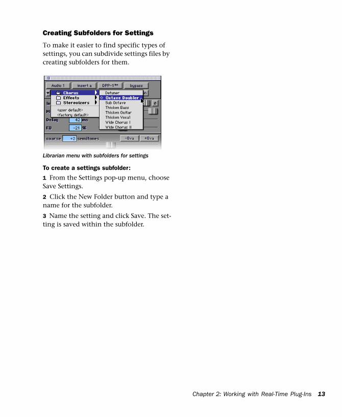
Creating Subfolders for Settings
To make it easier to find specific types of settings, you can subdivide settings files by creating subfolders for them.
To create a settings subfolder:
1 From the Settings pop-up menu, choose Save Settings.
2 Click the New Folder button and type a name for the subfolder.
3 Name the setting and click Save. The set-ting is saved within the subfolder.
Librarian menu with subfolders for settings
Chapter 2: Working with Real-Time Plug-Ins 13
14
DigiRack Plug-Ins Guide
chapter 3
Working with AudioSuite Plug-Ins
AudioSuite plug-ins differ from TDM and RTAS plug-ins in that they are not used non-destructively in real time, but are in-stead used to process and modify audio files on disk. Depending on how you con-figure a non-real-time AudioSuite plug-in, it will either alter the original source audio file or create an entirely new audio source file.
AudioSuite plug-ins are accessed through the AudioSuite menu.
AudioSuite menu
AudioSuite Plug-Ins Compressor Processes audio with compres-sion
LImiter Processes audio with limiting
Gate Processes audio with gating
Expander Gate Processes audio with ex-pander-gating
De-esser Processes audio with de-essing
1-band EQ II Processes audio with hi-pass, lo-shelf, hi-shelf, lo-pass or peak EQ filters, in a 1-band or 4-band module
4-band EQ II Processes audio with hi-pass, lo-shelf, hi-shelf, lo-pass or peak EQ filters, in a 1-band or 4-band module
Invert Inverts phase (polarity)
Duplicate Creates a new, continuous source audio file (and region) from the selection
Short Delay Adds up to 18 ms of delay
Slap Delay Adds up to 157 ms of delay
Medium Delay Adds up to 366 ms of delay
Long Delay Adds up to 3658 ms of delay
Normalize Uniformly adjusts all levels in a region or regions to a user-definable level, using the loudest peak in the audio file as the reference
Chapter 3: Working with AudioSuite Plug-Ins 15
16
Gain Allows variable gain (volume) change, in decibels or percentage before clip
Reverse Rewrites selected audio in reverse
DC Offset Removal Recognizes and removes DC offset from audio files
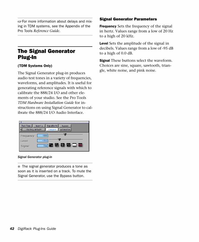
Signal Generator Generates audio tones for equipment calibration purposes
Time Compression/Expansion Changes an audio file’s duration with or without changing its pitch
Pitch Shift Changes an audio file’s pitch with or without changing its duration
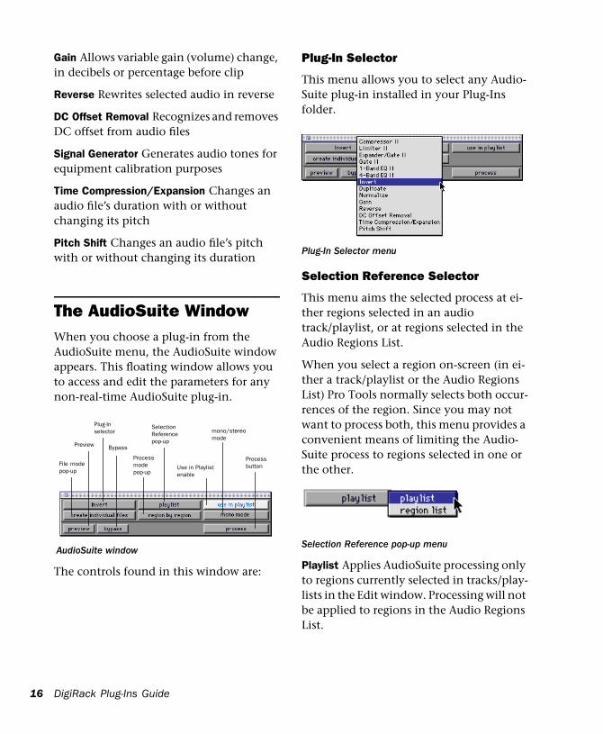
The AudioSuite WindowWhen you choose a plug-in from the AudioSuite menu, the AudioSuite window appears. This floating window allows you to access and edit the parameters for any non-real-time AudioSuite plug-in.
The controls found in this window are:
AudioSuite window
File modepop-up
Plug-Inselector
Bypass
Processmodepop-up
SelectionReferencepop-up
Processbutton
Preview
Use in Playlist enable
mono/stereomode
DigiRack Plug-Ins Guide
Plug-In Selector
This menu allows you to select any Audio-Suite plug-in installed in your Plug-Ins folder.
Selection Reference Selector
This menu aims the selected process at ei-ther regions selected in an audio track/playlist, or at regions selected in the Audio Regions List.
When you select a region on-screen (in ei-ther a track/playlist or the Audio Regions List) Pro Tools normally selects both occur-rences of the region. Since you may not want to process both, this menu provides a convenient means of limiting the Audio-Suite process to regions selected in one or the other.
Playlist Applies AudioSuite processing only to regions currently selected in tracks/play-lists in the Edit window. Processing will not be applied to regions in the Audio Regions List.
Plug-In Selector menu
Selection Reference pop-up menu
Region List Applies AudioSuite processing only to regions currently selected in the Audio Regions List. Processing will not be applied to regions located in tracks/playl-ists in the Edit window.
▲ If an AudioSuite plug-in supports stereo pro-cessing, the Selection Reference must be set to Playlist for the mono/stereo processing se-lector to be available.
Use in Playlist Button
This button determines whether the AudioSuite plug-in will replace all instances of the selected regions everywhere in the session, or only the occurrences of the re-gions that are currently selected.
Use In Playlist Off When Use in Playlist is disabled, only the currently selected region will be replaced.
Use In Playlist On, Reference = Region List When Use in Playlist is enabled and the Se-lection Reference pop-up menu is set to Re-gions List, all copies of the selected region will be replaced everywhere in the session.
Use In Playlist On, Reference = Playlist When Use in Playlist is enabled and the Se-lection Reference menu is set to Playlist, only regions selected in tracks in the Edit window will be replaced. If the session in-cludes other copies of the region used in other playlists, those copies of the original, unprocessed region will not be replaced.
Use in Playlist button
▲ If the Selection Reference pop-up menu is set to Region List, the Use in Playlist button will automatically be disabled to ensure that you do not accidentally replace every occur-rence of the region in a session.
File Mode Selector
This menu allows you to select whether or not the AudioSuite plug-in will process the selected audio destructively or non-de-structively, and how the original files will be modified.
There are three options:
Overwrite Processes the selected regions de-structively, overwriting the original audio. Not all AudioSuite plug-ins can be used de-structively.
Create Individual Files Processes the se-lected regions non-destructively, creating a new audio file for each region. The new audio files are added to the session, leaving the original source audio files in the Re-gions List unchanged. (Whether the pro-cessed audio is added to the current playlist or only to the Regions List, is determined by the Selection Reference setting, as ex-plained earlier.)
Create Continuous File Processes the se-lected regions non-destructively and cre-ates a new audio file consisting of the se-lected regions “glued” into a into a single,
File Mode pop-up menu
Chapter 3: Working with AudioSuite Plug-Ins 17
18
unbroken region. This mode is particularly useful if you are assembling a composite track from multiple takes.
✽ The Create Continuous File option is not available with some time domain plug-ins. To achieve a similar result, use the Duplicate plug-in to glue together regions processed with these plug-ins.
Process Mode Selector
If you have made a selection which in-cludes multiple regions, this pop-up menu allows you to specify whether AudioSuite processing is performed on a region-by-re-gion, or entire-selection basis.
Region by Region Analyzes each region in a selection individually, rather than over the entire multi-region selection as a whole.
Entire Selection Uses the entire selection for analysis. All regions will be analyzed and processed relative to the peak level within the entire selection.
Track Process Mode Selector
If you have made a selection which in-cludes regions from multiple tracks, some AudioSuite plug-ins allow you to choose whether you want to perform processing on a track-by-track, or an all-tracks basis.
Track Process Mode Selector
DigiRack Plug-Ins Guide
This pop-up has the same effect as the Pro-cess Mode Selector, with one important distinction: the Process mode pop-up con-trols region processing within each track. The Track Process Mode Selector, on the other hand, lets you choose to apply the current AudioSuite process to each track in-dividually, or to all tracks collectively.
Peak On Each Track Analyzes each selected track individually. If you apply the Normal-ize plug-in to multiple tracks in Peak on Each Track mode, for example, each track will be Normalized without regard to the other selected tracks.
Peak From All Tracks Uses all currently se-lected tracks for analysis. If you apply the Normalize plug-in to multiple tracks in Peak From All Tracks mode, for example, the tracks will be analyzed as a single entity and regions will be normalized relative to the peak level within all selected tracks.
Preview Button
The Preview button allows you to audition the effect of a plug-in before you process the audio. By adjusting the plug-in param-eters while you listen to this audio preview, you can fine-tune the effect. Not all Audio-Suite plug-ins support this feature.
Before you use Preview, be aware that:
◆ The performance of the Preview function depends on the speed of your CPU. Faster computers preview AudioSuite effects bet-ter than slower computers.
◆ On Macintosh computers, the preview function’s output level is controlled by the Macintosh Sound Manager, not by the fader level of the track containing the re-gion. To adjust Preview volume level, use the Sound Control Panel in the Apple Menu.
◆ Regardless of how many tracks/regions are currently selected, the Preview button will only play the first selected track if a plug-in is in mono mode, or the first two consecutive tracks if the plug-in is in stereo mode.
◆ If you are using Region-by-Region pro-cessing mode, the Preview function will preview only the first region within a multi-region selection. To hear all selected regions, temporarily select Create Continu-ous File from the File Mode menu before previewing.
◆ The Preview function always routes audio to channels 1-2 of an Audio Inter-face.
◆ The Preview function is affected by the AudioSuite Buffer Size parameter (on the Processing page of the Pro Tools Prefer-ences dialog). See “The AudioSuite Process-ing Preferences Dialog” on page 20.
Bypass
Clicking this button previews the selected audio without the effect of the current AudioSuite plug-in. When Bypass is en-abled, the selected audio is auditioned without AudioSuite processing. The Bypass button applies only to previewing. It does not affect actual AudioSuite processing.
Process
Clicking this button begins AudioSuite pro-cessing of the selected audio. Processing can occur during playback (though it may take slightly longer). Processed files are auto-named with the region or audio file’s name plus an acronym for the chosen AudioSuite process.
New files are written to the hard disk spec-ified for that track in the Disk Allocation dialog, or to the same drive as the original file if the region is not currently on a track. See “Auto-File Naming of AudioSuite-Pro-cessed Audio” on page 20.
Stereo Processing
If the AudioSuite plug-in you want to use supports stereo processing, regions can be selected and processed as a stereo pair as long as they occur at the same time loca-tion on their respective playlists.
✽ Group tracks that form stereo pairs. This will allow you to quickly select them on-screen. Also, name stereo pairs with suffixes such as “L/ R” (for example, “Drums.L” and “Drums.R”). This will keep pairs of audio files/regions together in the Regions List, and make it easy to select them for AudioSuite pro-cessing.
Undoing AudioSuite Processing
If you have processed an audio selection non-destructively, the Undo and Redo commands allow you to undo the selected AudioSuite process. You can undo/redo an AudioSuite process during audio playback.
Chapter 3: Working with AudioSuite Plug-Ins 19
20
Since Pro Tools allows a single level of Undo, if you perform any edit operation immediately following a non-destructive AudioSuite process, you will no longer be able to undo that process.
▲ Undo is not available when a plug-in is con-figured for destructive editing since the pro-cess has already overwritten the source audio file.
Auto-File Naming of AudioSuite-Processed Audio
When new audio files are created as a result of AudioSuite processing, Pro Tools will auto-name these files according to the type of plug-in used. The name of the region de-termines the prefix, while the type of AudioSuite plug-in determines the suffix.
Auto file-naming follows these rules:
◆ New regions are named beginning with the region name, followed by an abbrevia-tion of the current AudioSuite process, fol-lowed by standard Pro Tools file and region numbering.
◆ If a plug-in’s File Mode pop-up is set to Overwrite, the original region’s name will not be changed.
◆ If a plug-in’s File Mode pop-up is set to Create Individual Files, the resulting re-gions will have an abbreviated version of the plug-in name appended to them.
DigiRack Plug-Ins Guide
Other AudioSuite Parameters
In addition to the standard AudioSuite pa-rameters, there are a number of special-pur-pose controls found on certain plug-ins:
Plug-In Librarian/Settings Menus The Set-tings and Librarian pop-up menus that ap-pear in some AudioSuite plug-ins provide a means of saving, loading, copying, pasting and organizing custom plug-in settings files. See “Using the Librarian” on page 11.
Analyze Button Allows you to analyze a se-lection without actually processing it. On the DigiRack Gain plug-in, the Analyze fea-ture allows you to determine the maxi-mum peak level on a track at a specific gain value before you process the audio.
Key Input Selector Allows you to select a track/bus to be used to trigger processing. In order to use this feature, the key input source audio must occur at the same time as the target audio. See “Using a Key Input for Side Chain Processing” on page 9.
The AudioSuite Processing Preferences DialogBefore you begin using AudioSuite plug-ins, use the Preferences dialog (Setups > Preferences > Processing) to configure de-fault AudioSuite parameters according to your needs. These parameters include the default dither setting, a dither on/off checkbox, and the AudioSuite buffer size parameter.
Default Dither AudioSuite plug-ins always create files which inherit the session’s bit depth. The Default Dither menu allows you to choose the dither algorithm used for dithering higher-bit source files during AudioSuite processing. When Use Default Dither is selected, the chosen dither algo-rithm will be used during any AudioSuite processing. Using dither with your Audio-Suite processing is most useful when work-ing with low-level files that contain a fade in or fade out.
The following AudioSuite plug-ins auto-matically apply dither when processing: • EQ II• Compressor II• Limiter II• Gate II• Expander/Gate II• Normalize• Gain
Processing Preferences page
• DC Offset Removal• Time Compression/Expansion• Pitch Shift
Edit Dither Settings Allows you to access any options for the presently selected De-fault Dither plug-in. In the case of the Digidesign Dither plug-in, this allows you to turn noise shaping on or off. The default position of the Noise Shape button is On.
☞ See “Noise Shaping” on page 38 for more information.
Dither Depth Allows you to choose the de-fault bit depth used by the dither function during AudioSuite processing. Bit depth can be set to 16-, 18-, 20-, or 24-bit.
☞ For an explanation of dither, See “The Dither Plug-In” on page 37.
AudioSuite Buffer Size Allows you to set the size of Pro Tools memory buffer for pro-cessing and previewing AudioSuite plug-ins. Choices are Mini, Small, Medium, Large, or Jumbo. In general, choosing a smaller buffer speeds up AudioSuite pre-viewing functions. Choosing a larger buffer speeds up AudioSuite processing of audio files.
To configure the AudioSuite Buffer Size:
1 Choose Setups > Preferences.
2 Click Processing.
3 Select an AudioSuite Buffer Size. Your choice will depend on whether you want to give priority to the length of the audio pre-view, or to the speed at which the Plug-in can process the selected audio.
4 Click Done.
Chapter 3: Working with AudioSuite Plug-Ins 21
22
Though the default setting will work well for most situations, you may want to set the buffer according to your current task: Before you audition an AudioSuite plug-in, set this buffer to Mini or Small. Then, when you are ready to process a file, reset it to Large or Jumbo.
Default TC/E Settings Allows you to select the Time Compression & Expansion set-tings used when editing with the Scrub Trimmer.
Using AudioSuite Plug-InsAudioSuite plug-ins can be applied to whole regions, partial regions, or selections that are made up of whole and partial re-gions across one or more tracks.
When audio selected in the Edit window includes partial regions, the regions will automatically be split into two or more re-gions when they are processed. Processing will occur only on the selection, leaving other regions unchanged.
Selecting Tracks for AudioSuite ProcessingBecause AudioSuite processes are per-formed on the specific regions that you se-lect, it is important that you select only those regions you actually want to process.
Selecting a region in the Audio Regions List will automatically select it in a track (if it currently resides on one). This is Pro Tools default behavior. You can change this, however, using the Region Selection Fol-lows Track Selection, and Track Selection Follows Regions List Selection options in
DigiRack Plug-Ins Guide
the Editing page of the Preferences dialog. See the Pro Tools Reference Guide for an ex-planation of these Preferences.
Selecting Tracks for Delay or Reverb ProcessingBecause some AudioSuite effects such as de-lay and reverb add additional material to the end of the selected audio (a reverb tail or a delay tap), it is very important that you make a selection that is longer than the original source material so that the plug-in can write it into the audio file.
If you select only the original material, without leaving additional space at the end, a reverb decay or delay that occurs af-ter the end of the region will be cut off.
To accommodate for this, place the region in a track, and select the desired audio plus an amount of blank space at the end of the region equal to the amount of delay or re-verb decay that you have added in the plug-in. The plug-in will then have space at the end of the region in which to write the final delay/decay.
To process audio with an AudioSuite Plug-in:
1 Select the desired regions in the target track(s) and/or in the Audio Regions List. Shift-click to select multiple regions. Only regions that are selected will be processed.
2 Choose the desired AudioSuite plug-in from the AudioSuite menu.
3 Click the Preview button to begin play-back of the selected material.
4 Adjust the plug-in parameters to achieve the effect that you want. These settings will determine how the file is processed and what effect the processing will have on the original regions. Here are some guidelines:
◆ To process the selected region only in the track in which it appears, choose Playlist from the Selection Reference pop-up. Alter-natively, if you want to process the selected region in the Audio Regions list only, choose Region List from this pop-up.
◆ If you want to process and update every occurrence of the selected region through-out your session, enable the Use In Playlist button (and also choose Region List from the Selection Reference pop-up). Alterna-tively, if you do not want to update every occurrence of the selected region, disable the Use In Playlist button.
◆ To configure the plug-in for destructive processing, choose Overwrite Files from the File Mode pop-up menu. This will over-write and permanently modify the original source audio files.
◆ Alternatively, to configure the plug-in for non-destructive processing, choose Create Individual Files from the File Mode pop-up menu. This will create new audio files that have been processed with the AudioSuite Plug-in and leave the original source audio files untouched.
◆ If you have selected multiple regions for processing and want to create a new file that connects and consolidates all of these regions together, choose Create Continu-ous File from the File Mode pop-up menu.
5 Finally, when you are ready, click the Pro-cess button. The selected audio is processed according to the settings you have speci-fied. Pro Tools appends an acronym to the region’s name indicating the AudioSuite process that has been applied. The new audio files then appear in your session.
✽ Grouping tracks that consist of stereo pairs will allow you to quickly select them on-screen.
✽ Name stereo pairs with suffixes such as “L/ R” (for example, “Drums.L” and “Drums.R”). This will keep pairs of audio files/regions to-gether in the Audio Regions List, and make it easy to select them for AudioSuite processing.
Chapter 3: Working with AudioSuite Plug-Ins 23
24
DigiRack Plug-Ins Guide
chapter 4
DigiRack Real-Time TDM and RTAS Plug-Ins
EQ II Plug-InsThe DigiRack EQs included with Pro Tools feature a 1-band and a 4-band EQ. The 4-band EQ provides a wider range of control over the frequency spectrum of an audio signal and thus requires more DSP.
1-band EQ plug-in
Chapte
Adjusting EQA useful way to audition an EQ is to in-crease or decrease its gain several dB then sweep the frequency up or down until you hear its effect. You can then make more precise adjustments to the settings.
4-band EQ plug-in
r 4: DigiRack Real-Time TDM and RTAS Plug-Ins 25
26
EQ II Parameters
Input Controls the input gain of the EQ, al-lowing you to prevent clipping. Since Pro Tools inserts are pre-fader, plug-ins used as inserts can cause clipping if their levels are boosted excessively.
Phase Invert Inverts the phase (polarity) of the input signal, allowing you to change frequency response characteristics between multi-miked sources (a common technique for miking a guitar cabinet), or to correct for miswired microphone cables.
Type Allows you to select an EQ type (high-pass, low-shelf, peak, high-shelf or low-pass).
Freq Designates the center of the frequency region to be cut or boosted.
Gain Controls the amount that the selected frequencies are cut or boosted.
Q Sets the bandwidth of the Peak filter. Higher values represent narrower band-widths. Lower numbers represent wider bandwidths. This parameter is only avail-able on the Peak EQ.
Bypass Bypasses the EQ. The 4-Band EQ has individual Bypass buttons for each band (the black buttons with appropriate EQ curve icons), as well as the standard all-band Bypass button at the top of the In-serts/Sends Editor window.
Bypass EQ band button on the 4-band EQ
DigiRack Plug-Ins Guide
High Pass Filter Attenuates all frequencies below the selected cutoff frequency setting at a rate of 12dB per octave while allowing all others above to pass through. For this reason, no gain control is available for this filter. High Pass filters can be useful for re-moving low frequency rumble or thinning out the lower end of a sound for special ef-fects such as simulating a telephone effect.
Low-Shelf EQ Produces a lift or a cut below the specified frequency.
Peak EQ Boosts or cuts only those frequen-cies centered around the selected center frequency. The Q button sets the band-width of the Peak filter. This determines the width of the filter’s overall slope — from a broad bell shape to a narrow notch. Broad curves tend to be most useful for musical applications. Narrow curves are useful for special purpose processing such as hum re-moval. Higher values represent narrower bandwidths. Lower numbers represent wider bandwidths.
High-Shelf EQ Produces a lift or a cut at and above the specified frequency.
Low Pass filter Attenuates all frequencies above the selected cutoff frequency setting at a rate of 12 dB per octave while allowing all others below to pass through. For this reason, no gain control is available for this filter.
Dynamics II Plug-Ins There are five types of DigiRack dynamics processors: Compressor, Limiter, Gate, Ex-pander/Gate and De-esser.
Compressor II
The Compressor reduces the dynamic range of signals that exceed a selected threshold by a specific amount. The in-crease of input signal needed to cause a 1dB increase in the output signal of the com-pressor is called the compression ratio. With a ratio of 4:1, for example, an 8dB in-crease of input produces a 2dB increase in the output.
Audio material often varies in loudness, and can be above the threshold at one mo-ment and below it the next. The Attack slider sets the compressor’s response time, or attack. The Release slider sets the amount of time that it takes for the com-pressor’s gain to return to its original level.
Compressor II plug-in
Chapte
Using Compression Effectively
To use compression most effectively, the at-tack time should be set so that signals ex-ceed the threshold level long enough to cause an increase in the average level. This helps ensure that gain reduction doesn’t decrease the overall volume.
Release times should be set long enough that if signal levels repeatedly rise above the threshold, they cause gain reduction only once. If the release time is too long, a loud section of the audio material could cause gain reduction that persists through a soft section. Of course, compression has many creative uses that break these rules.
The Compressor has built-in metering that allows you to monitor the amount of gain reduction taking place. The gain reduction meter usually remains at 0 level when the input signal is below the threshold and falls to the left to show the amount of gain reduction in decibels when the input signal exceeds the threshold.
▲ Compressor settings created in version 5.x and later of Pro Tools are not compatible with earlier versions. Saving a session in a pre- 5.x format will cause Compressor settings to be lost.
Compressor Parameters:
Phase Invert Inverts the phase (polarity) of the input signal, allowing you to change frequency response characteristics between multi-miked sources or to correct for mis-wired microphone cables.
Gain Provides overall output gain adjust-ment. It allows you to compensate for heavily compressed signals.
r 4: DigiRack Real-Time TDM and RTAS Plug-Ins 27
28
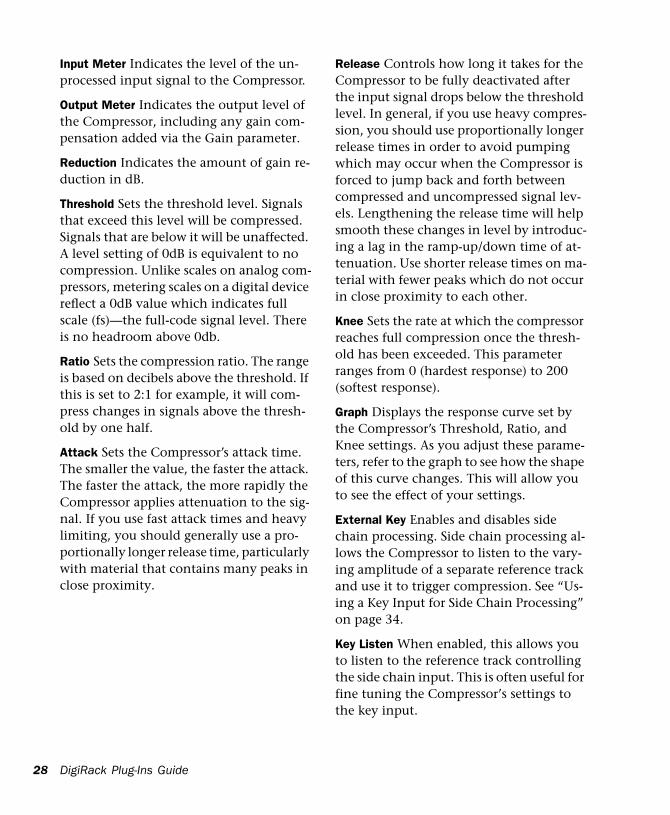
Input Meter Indicates the level of the un-processed input signal to the Compressor.
Output Meter Indicates the output level of the Compressor, including any gain com-pensation added via the Gain parameter.
Reduction Indicates the amount of gain re-duction in dB.
Threshold Sets the threshold level. Signals that exceed this level will be compressed. Signals that are below it will be unaffected. A level setting of 0dB is equivalent to no compression. Unlike scales on analog com-pressors, metering scales on a digital device reflect a 0dB value which indicates full scale (fs)—the full-code signal level. There is no headroom above 0db.
Ratio Sets the compression ratio. The range is based on decibels above the threshold. If this is set to 2:1 for example, it will com-press changes in signals above the thresh-old by one half.
Attack Sets the Compressor’s attack time. The smaller the value, the faster the attack. The faster the attack, the more rapidly the Compressor applies attenuation to the sig-nal. If you use fast attack times and heavy limiting, you should generally use a pro-portionally longer release time, particularly with material that contains many peaks in close proximity.
DigiRack Plug-Ins Guide
Release Controls how long it takes for the Compressor to be fully deactivated after the input signal drops below the threshold level. In general, if you use heavy compres-sion, you should use proportionally longer release times in order to avoid pumping which may occur when the Compressor is forced to jump back and forth between compressed and uncompressed signal lev-els. Lengthening the release time will help smooth these changes in level by introduc-ing a lag in the ramp-up/down time of at-tenuation. Use shorter release times on ma-terial with fewer peaks which do not occur in close proximity to each other.
Knee Sets the rate at which the compressor reaches full compression once the thresh-old has been exceeded. This parameter ranges from 0 (hardest response) to 200 (softest response).
Graph Displays the response curve set by the Compressor’s Threshold, Ratio, and Knee settings. As you adjust these parame-ters, refer to the graph to see how the shape of this curve changes. This will allow you to see the effect of your settings.
External Key Enables and disables side chain processing. Side chain processing al-lows the Compressor to listen to the vary-ing amplitude of a separate reference track and use it to trigger compression. See “Us-ing a Key Input for Side Chain Processing” on page 34.
Key Listen When enabled, this allows you to listen to the reference track controlling the side chain input. This is often useful for fine tuning the Compressor’s settings to the key input.
Limiter II
The Limiter is used to prevent signal peaks from ever exceeding a chosen level so that they don’t overload amplifiers or recording devices. Most limiters have ratios of 10:1 or 20:1, although some provide ratios of up to 100:1. Large ratios effectively limit the dy-namic range of the signal to a specific value by setting an absolute ceiling for the dy-namic range.
Limiting is used to prevent short-term peaks from reaching their full amplitude. Used judiciously, limiting allows you to achieve higher average levels, while avoid-ing overload (clipping or distortion), by limiting only some short-term transients in the source audio. To prevent the ear from hearing the gain changes, extremely short attack and release times are used.
Limiting is used to remove only occasional peaks because gain reduction on successive peaks wouldn’t be noticeable. If audio ma-terial contains many peaks, the threshold
Limiter II plug-in
Chapte
should be raised and the gain manually re-duced so that only occasional, extreme peaks are limited.
The Limiter’s ratio is internally set to 100:1, and the Attack time is automatically set to 0 milliseconds. The Limiter is similar to heavy compression. It can be useful for re-ducing pops and clicks, or for hard-limiting dynamic range for broadcast or band-lim-ited mediums such as cassette.
Limiter Parameters
Phase Invert Inverts the phase (polarity) of the input signal, allowing you to change frequency response characteristics between multi-miked sources or to correct for mis-wired microphone cables.
Gain Provides overall output gain adjust-ment.
Input Meter Indicates the level of the un-processed input signal to the Limiter.
Output Meter Indicates the output level of the Limiter, including any gain compensa-tion added via the Gain parameter.
Reduction Indicates the amount by which the signal is being attenuated.
Threshold Sets the threshold level. Signals that exceed this level will be limited. Sig-nals that are below it will be unaffected.
Attack Sets the Limiter’s attack time. The smaller the value, the faster the attack. The faster the attack, the more rapidly the Lim-iter applies attenuation to the signal. If you use fast attack times and heavy limiting, you should generally use a proportionally longer release time, particularly with mate-rial that contains many peaks in close prox-imity.
r 4: DigiRack Real-Time TDM and RTAS Plug-Ins 29
30
Release Controls how long it takes for the Limiter to be fully deactivated after the in-put signal drops below the threshold level. In general, if you use heavy limiting, you should use proportionally longer release times in order to avoid pumping which may occur when the Limiter is forced to jump back and forth between limited and unlimited signal levels. Lengthening the release time will help smooth these changes in level by introducing a lag in the ramp-up/down time of attenuation. Use shorter release times on material with fewer peaks which do not occur in close proximity to each other.
Graph Displays the response curve set by the Limiter’s Threshold setting. As you ad-just these parameters, refer to the graph to see how the shape of this curve changes. This will allow you to see the effect of your settings.
External Key Enables and disables side chain processing. Side chain processing al-lows the Limiter to listen to the varying amplitude of a separate reference track and use it to trigger limiting. See “Using a Key Input for Side Chain Processing” on page 34.
Key Listen When enabled, this allows you to listen to the reference track controlling the side chain input. This is often useful for fine tuning the Limiter’s settings to the key input.
DigiRack Plug-Ins Guide
Gate II
The Gate (also known as a noise gate) al-lows a signal above the selected threshold to be passed through to the output at unity gain, without dynamic processing. Once the input signal falls below the threshold level, the gating shuts down the signal by fully or partially attenuating the output. In this way, the desired signal is allowed to pass, but unwanted signal is not. The Gate is useful for noise removal on individual tracks, and can be used for special effects such as cutting off a reverb tail.
Gate Parameters
Phase Invert Inverts the phase (polarity) of the input signal, allowing you to change frequency response characteristics between multi-miked sources or to correct for mis-wired microphone cables.
Gating Indicates the amount of reduction in dB.
Threshold Sets the threshold level. Signals that exceed this level will pass through. Sig-nals that are below it will be gated, depend-
Gate II plug-in
ing on the settings of the Attack, Hold, De-cay, and Range parameters (explained below).
Attack Sets the attack time of the Gate.
Hold Specifies a duration (in seconds or mil-liseconds) that the Gate will stay open after the initial attack cycle. This can be used as a one-shot function to keep the Gate open for longer periods of time with a single crossing of the threshold. It can also be used to prevent gate chatter which may oc-cur if varying input levels near the thresh-old cause the Gate to open and close very rapidly.
Decay Controls how long it takes for the Gate to close after the signal falls below the threshold level.
Range Sets the depth of the Gate when closed. It has a maximum depth of -80db. Setting the gate to higher range levels al-lows more of the gated audio that falls be-low the threshold to peek through the gate at all times. This is useful for things such as drum leakage, where you may want to sup-press the overall drum kit sound by a spe-cific amount, while emphasizing the gated instrument such as a snare.
Graph Displays the response curve set by the Gate’s Threshold and Range settings. As you adjust these parameters, refer to the graph to see how the shape of this curve changes. This will allow you to see the ef-fect of your settings.
External Key Enables and disables side chain processing. Side chain processing al-lows the Gate to listen to the varying am-plitude of a separate reference track and use it to trigger limiting. See “Using a Key In-put for Side Chain Processing” on page 34.
Chapte
Key Listen When enabled, this allows you to listen to the reference track controlling the side chain input. This is often useful for fine tuning the Gate’s settings to the key input.
Expander/Gate II
The Expander/Gate reduces noise by de-creasing the gain of signals that fall below a user-selectable threshold. Expanders are particularly useful for reducing noise or sig-nal leakage that creeps into recorded mate-rial as its level falls, as often occurs in the case of headphone leakage.
Expanders can be thought of as soft noise gates since they provide a gentler way of cutting off noisy low-level signals than the typically abrupt cutoff of a gate. If you want, however, you can actually use this plug-in as a gate, simply by setting the Ra-tio to its maximum value and using short attack, decay, and release settings.
Expander/Gate II plug-in
r 4: DigiRack Real-Time TDM and RTAS Plug-Ins 31
32
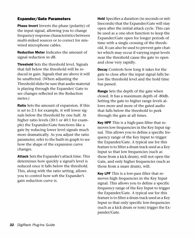
Expander/Gate Parameters
Phase Invert Inverts the phase (polarity) of the input signal, allowing you to change frequency response characteristics between multi-miked sources or to correct for mis-wired microphone cables.
Reduction Meter Indicates the amount of signal reduction in dB.
Threshold Sets the threshold level. Signals that fall below the threshold will be re-duced in gain. Signals that are above it will be unaffected. (When adjusting the Threshold slider be sure that audio material is playing through the Expander/ Gate to see changes reflected in the Reduction meter.)
Ratio Sets the amount of expansion. If this is set to 2:1 for example, it will lower sig-nals below the threshold by one half. At higher ratio levels (30:1 or 40:1 for exam-ple) the Expander/Gate functions like a gate by reducing lower level signals much more dramatically. As you adjust the ratio parameter, refer to the built-in graph to see how the shape of the expansion curve changes.
Attack Sets the Expander’s attack time. This determines how quickly a signal’s level is reduced once it falls below the threshold. This, along with the ratio setting, allows you to control how soft the Expander’s gain reduction curve is.
DigiRack Plug-Ins Guide
Hold Specifies a duration (in seconds or mil-liseconds) that the Expander/Gate will stay open after the initial attack cycle. This can be used as a one-shot function to keep the Expander/Gate open for longer periods of time with a single crossing of the thresh-old. It can also be used to prevent gate chat-ter which may occur if varying input levels near the threshold cause the gate to open and close very rapidly.
Decay Controls how long it takes for the gate to close after the input signal falls be-low the threshold level and the hold time has passed.
Range Sets the depth of the gate when closed. It has a maximum depth of -80db. Setting the gate to higher range levels al-lows more and more of the gated audio that falls below the threshold to peek through the gate at all times.
Key HPF This is a high-pass filter that re-moves low frequencies in the Key Input sig-nal. This allows you to define a specific fre-quency range of the Key Input to trigger the Expander/Gate. A typical use for this feature is to filter a drum track used as a Key Input so that low frequencies (such as those from a kick drum), will not open the Gate, and only higher frequencies (such as those from a snare drum), will.
Key LPF This is a low-pass filter that re-moves high frequencies in the Key Input signal. This allows you to define a specific frequency range of the Key Input to trigger the Expander/Gate. A typical use for this feature is to filter a drum track used as a Key Input so that only specific low-frequencies (such as a kick drum or tom) trigger the Ex-pander/Gate.
Graph Displays the response curve set by the Expander/Gate’s Threshold, Ratio, and Range settings. As you adjust these param-eters, refer to the graph to see how the shape of this curve changes. This will allow you to see the effect of your settings.
External Key Enables and disables side chain processing. Side chain processing al-lows the Expander/Gate to listen to the varying amplitude of a separate reference track and use it to trigger expansion.
Key Listen When enabled, this allows you to listen to the reference track controlling the side chain input. This is often useful for fine tuning the Expander/Gate’s settings to the key input.
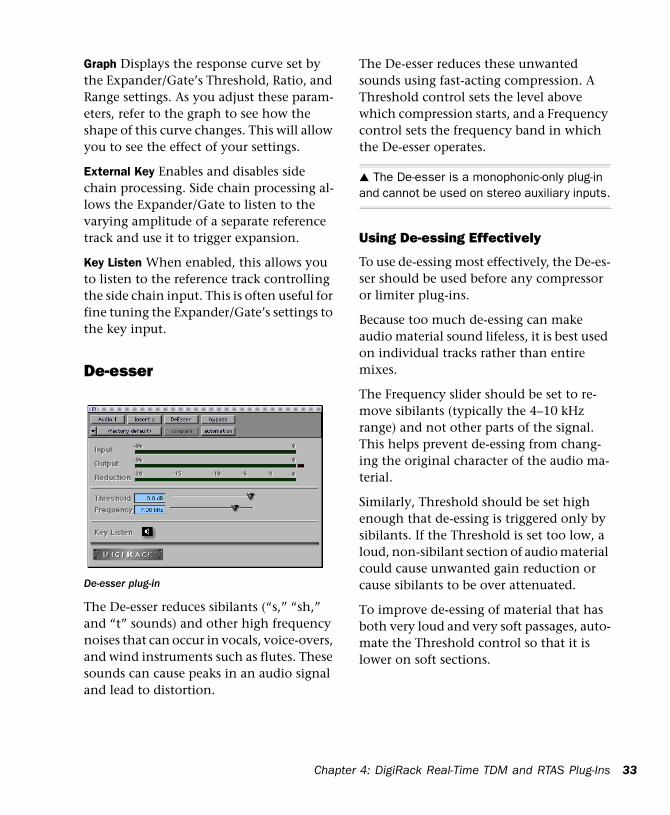
De-esser
The De-esser reduces sibilants (“s,” “sh,” and “t” sounds) and other high frequency noises that can occur in vocals, voice-overs, and wind instruments such as flutes. These sounds can cause peaks in an audio signal and lead to distortion.
De-esser plug-in
Chapte
The De-esser reduces these unwanted sounds using fast-acting compression. A Threshold control sets the level above which compression starts, and a Frequency control sets the frequency band in which the De-esser operates.
▲ The De-esser is a monophonic-only plug-in and cannot be used on stereo auxiliary inputs.
Using De-essing Effectively
To use de-essing most effectively, the De-es-ser should be used before any compressor or limiter plug-ins.
Because too much de-essing can make audio material sound lifeless, it is best used on individual tracks rather than entire mixes.
The Frequency slider should be set to re-move sibilants (typically the 4–10 kHz range) and not other parts of the signal. This helps prevent de-essing from chang-ing the original character of the audio ma-terial.
Similarly, Threshold should be set high enough that de-essing is triggered only by sibilants. If the Threshold is set too low, a loud, non-sibilant section of audio material could cause unwanted gain reduction or cause sibilants to be over attenuated.
To improve de-essing of material that has both very loud and very soft passages, auto-mate the Threshold control so that it is lower on soft sections.
r 4: DigiRack Real-Time TDM and RTAS Plug-Ins 33
34
De-esser Parameters:
Input Meter Indicates the level of the un-processed input signal to the De-esser.
Output Meter Indicates the output level of the De-esser.
Reduction Indicates the amount of gain re-duction in dB. It remains at 0 level when the input signal is below the threshold.
Threshold Sets the threshold level. Signals that exceed this level will be compressed. Signals that are below it will be unaffected. A setting of 0 dB is equivalent to no de-ess-ing.
Frequency Sets the frequency band in which the De-esser operates. Frequencies in the specified range will be gain reduced. To find the optimum Frequency setting, sweep this control back and forth during audio playback.
Key Listen Monitors the sibilant peaks used by the De-esser as a key input to trigger compression. This is useful for listening only to the sibilance and fine tuning set-tings to remove them.
Using a Key Input for Side Chain ProcessingYou can use the side-chain processing capa-bilities of the Compressor, Limiter, Gate, or Expander/Gate to trigger any of these plug-ins from a separate reference track or exter-nal audio source.
DigiRack Plug-Ins Guide
By using the External Key input, you can control the dynamics of one audio signal using the dynamics of another signal (the key input). A typical use for this feature is to use one instrument to trigger gating of another: a kick drum to gate and tighten up a bass track, a rhythm guitar to gate a key-board pad, and many other creative appli-cations.
To use a key input for side chain processing:
1 Click the Insert pop-up on the desired track to select the desired plug-in.
2 Click the Side Chain Input pop-up and select the input/bus that carries the audio you want to use to trigger the plug-in.
3 Click the Key Input button. This acti-vates side chain processing.
4 If you want to hear the audio source you have selected to control side chain input, click the Key Listen button.
5 If you want to filter the Key Input so that only certain frequencies trigger the plug-in, use the Key HPF and Key LPF controls to se-lect the desired frequency range.
6 Begin playback. The plug-in is now using the input/bus that you chose as a side chain input to trigger its effect.
7 Adjust the plug-in’s Threshold parameter to fine tune the side chain triggering.
8 Adjust other parameters of the plug-in to achieve final effect that you want.
Mod Delay Plug-InsThe Mod Delay plug-in provides time de-lay-based effects. Effects obtained through the use of Mod Delay include slap echo, doubling, chorusing, and flanging.
There are four different Mod Delays, each of which is capable of a different maximum delay time:• The Short Delay provides 1024 samples
of delay (23.2 milliseconds at 44.1 kHz or 21.3 ms at 48 kHz).
• The Slap Delay provides 7186 samples of delay (162 ms at 44.1 kHz or 149 ms at 48 kHz).
• The Medium Delay provides 16384 sam-ples of delay (371 ms at 44.1 kHz kHz or 341 ms at 48 kHz).
• The Long Delay provides 162474 sam-ples of delay (3.68 seconds at 44.1 kHz or 3.38 seconds at 48 kHz).
Mod Delay plug-in
Chapte
▲ The Long Delay TDM plug-in is only available on systems equipped with a Pro Tools 24 MIX card.
The Mod Delay plug-ins can be cascaded on inserts one into another to achieve even longer delay times. If you do this, set the feedback of intermediate delays to zero to get predictable results. Use the feedback control of the last delay in the chain to set the number of repeats.
The Mod Delays are unique among the Di-giRack TDM plug-ins in that they each pro-vide a Mono In/Stereo Out option. Choos-ing a delay in the Mono In/Stereo Out format allows you to “stereoize” the output of a mono track. A track created in this way will then have stereo pan faders for con-trolling each channel of the stereo signal. As explained previously, any inserts that occur on a track after a stereo Insert will au-tomatically become stereo as well.
Mod Delay Parameters
Input Controls the input volume of the de-lay, allowing you to prevent clipping.
Wet/Dry Controls the balance between the delayed signal and the original signal. If you are using a delay for flanging or cho-rusing, you can control the depth of the ef-fect somewhat with the Wet/Dry setting.
LPF (Low Pass filter) Controls the cutoff frequency of the low-pass filter. This allows you to attenuate the high frequency con-tent of the feedback signal. The lower the setting, the more high frequencies are at-tenuated.
Delay Sets the delay time between the orig-inal signal and the delayed signal.
r 4: DigiRack Real-Time TDM and RTAS Plug-Ins 35
36
Depth Controls the depth of the modula-tion applied to the delayed signal.
Rate Controls the rate of modulation of the delayed signal.
Feedback Controls the amount of feedback applied from the output of the delay back into its input. It also controls the number of repetitions of the delayed signal. Nega-tive feedback settings give a more intense “tunnel-like” sound to flanging effects.
Procrastinator Extended Delay Plug-In(Pro Tools 24/Pro Tools III Systems Only)
The Procrastinator™ plug-in is designed to provide a long delay effect for TDM-based systems without a Pro Tools 24 MIX card, since systems without this card do not sup-port the Long Mod Delay plug-in.
Because it consumes considerably more processing power that the standard Mod Delay plug-ins,
Procrastinator plug-in
DigiRack Plug-Ins Guide
Procrastinator requires one entire DSP on a DSP Farm card per usage and is only avail-able in mono mode. It can be used in either 16-bit resolution or 24-bit resolution.
To obtain Procrastinator’s full two seconds of delay, use it in 16-bit mode. For higher bandwidth processing, and shorter maxi-mum delay time, use it in 24-bit mode. (If you choose 16-bit, the signal on that chan-nel will be processed at 16-bit resolution rather than the TDM mixing environ-ment’s standard 24-bit resolution.
▲ Procrastinator can only be used on systems with a DSP Farm card.
Procrastinator Parameters
Input Level Controls the input volume of Procrastinator, allowing you to prevent clipping. Pro Tools inserts are pre-fader and Plug-ins assigned to inserts can cause clip-ping if their levels are set too high.
It may sometimes be necessary to prevent clipping when using feedback. The LEDs next to the slider are for input monitoring; the green LED indicates signal present (-60dB) and the red indicates clipping. To re-set it, click it.
Mix Controls the balance between the de-layed signal and the original signal. The dry signal is implemented as passthrough with no added delay. The wet signal in-cludes the delayed signal with any specified feedback.
Delay Sets the delay time between the orig-inal signal and the delayed signal. Use it in conjunction with the feedback control to
generate a single echo or a series of echoes. Moving this slider during playback may cause undesirable audio artifacts.
Feedback (FB) Controls the amount of feedback (positive or negative) applied from the output of the delay back into its input. This allows you to control the num-ber of repetitions of the delayed signal.
The pre/post switch selects whether the feedback signal is taken pre-mix (wet only) or post-mix (actual output). Post-mix feed-back is affected by the Mix control setting. To see a signal path diagram illustrating the effect of the pre/post switches, click on the Procrastinator logo; it will display the cur-rent signal flow. Click again to return to the logo.
Low Pass Filter (LPF) Controls the cutoff frequency of the low-pass filter. This allows you to attenuate the high frequency con-tent of the feedback signal. The lower the setting, the more high frequencies are at-tenuated. Moving the slider all the way to the right sets it to the off position. The pre/post switch determines whether the LPF is pre-feedback (affects the initial de-layed repeat) or post-feedback (affects only the second and successive repeats).
Tempo-Related Controls
The remaining parameters of the Procrasti-nator plug-in provide you with an alternate method for entering a desired delay value. Rather than selecting a delay time, it allows you to set a tempo and the desired number of beats of delay.
Tempo Selects the desired tempo in beats per minute (bpm). This setting is indepen-dent of Pro Tools’ tempo. When a specific
Chapte
Duration is selected (see “Duration” below) moving this control will affect the Delay setting and vice-versa. Likewise, the range of both controls will be limited to the max-imum available delay with the currently se-lected Duration. To enter very slow tempos or short delays it may be necessary to dese-lect all Duration buttons.
Duration Specifies a desired delay from a musical perspective. Using the guideline of one beat is equal to one quarter note, enter the desired delay by selecting appropriate durations. You can enable multiple buttons by Shift-clicking them.
Groove Provides fine adjustment of the de-lay in percentages of a sixteenth note. It can be used to add a groove by slightly off-setting the delay from the precise beat of the track.
The Dither Plug-InThe Dither plug-in is designed for im-proved 16-, 18-, or 20-bit performance and reduced quantization noise when mixing or fading low-level audio signals.
Dither is a form of randomized noise used to minimize quantization errors in digital audio systems. Digital audio’s poorest dis-
Dither plug-in
r 4: DigiRack Real-Time TDM and RTAS Plug-Ins 37
38
tortion performance exists at the lowest end of the dynamic range, where quantiza-tion distortion can occur.
The introduction of dithering can reduce these quantizing errors with very low-level random noise, minimizing distortion prod-ucts as audio reaches low level. With dith-ering there is a trade-off between signal-to-noise performance and less-apparent dis-tortion. Proper use of dithering allows you to squeeze better subjective performance out of 16-bits.
The most common application of dithering is to use it on a master output mix as the last processor in the signal path when pre-paring a 24-bit session for CD mastering. In this case, you would place the Dither plug-in on a Master Fader as a post-fader Insert to reduce session bit-depth from 24-bits to 16-bits.
The Dither plug-in has user-selectable bit resolution and a noise shaping on/off op-tion.
✽ If you are outputting audio to an analog des-tination with a 24-bit-capable Pro Tools system and an 888/24 I/O, do not use dither. This al-lows maximum output fidelity from the 888/24 I/O’s high-performance 24-bit digital-to-analog convertors.
DigiRack Plug-Ins Guide
Noise ShapingThe Dither plug-in features a technique known as noise shaping to further improve audio performance and reduce perceived noise in low-level signals. Noise shaping utilizes digital filtering to remove noise that falls in the middle of the audio spec-trum (specifically, around 4 kHz). This is the range where human hearing is most sensitive.
In reality, since the noise plays an impor-tant role in reducing quantization errors (and thereby audio artifacts) the noise is not reduced in total, but is shifted into a range where it is harder to hear. Essentially, noise shaping lessens our perception of the noise inherent in dithering schemes by shifting audible noise components into a less audible range.
Dither and Output Bit ResolutionDither has two user-selectable parameters that allow you to optimize its operation:
Bit Resolution
This pop-up menu allows you to choose one of three possible resolutions for the Dither processing. As a general rule, you should set this parameter to the maximum bit resolution of your destination.
16-bit Recommended for output to digital devices such as DAT recorders and CD re-corders, since they have a maximum reso-lution of 16-bits.
18-bit Recommended for output to analog devices if you are using a Pro Tools 888 I/O or 882 I/O Audio Interface since this is the maximum resolution available from the 18-bit digital-to-analog convertors of these devices.
20-bit Recommended for output to digital devices that support a full 20-bit recording data path, such the Sony PCM-9000 optical mastering recorder, or the Alesis ADAT XT 20. This setting is also recommended for output to analog devices if you are us-ing a Pro Tools 882/20 I/O Audio Interface. The 20-bit setting can also be used with digital effects devices that support 20-bit input and output, since it provides for a lower noise floor and greater dynamic range when mixing 20-bit signals directly into the TDM environment.
If you want, you can choose not to use the Dither plug-in and instead utilize the full 24-bit resolution of Pro Tools’ digital out-put, depending on your destination device. As noted previously, if you have a 24-bit-capable Pro Tools system with an 888/24 I/O Audio Interface and are output-ting audio to an analog destination, we rec-ommend that you do not use dither.
Noise Shape
This button engages or disengages Noise Shaping. When lit, noise shaping is on. See the previous section regarding Noise Shap-ing for more information.
☞ See the Pro Tools Reference Guide for de-tails on using the Dither plug-in during mix-down.
Chapte
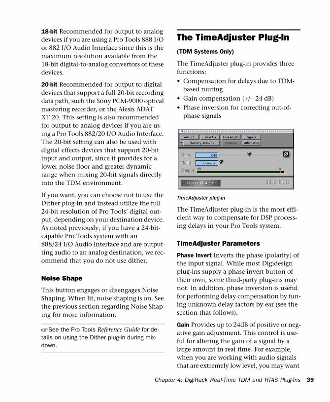
The TimeAdjuster Plug-In(TDM Systems Only)
The TimeAdjuster plug-in provides three functions: • Compensation for delays due to TDM-
based routing• Gain compensation (+/– 24 dB)• Phase inversion for correcting out-of-
phase signals
The TimeAdjuster plug-in is the most effi-cient way to compensate for DSP process-ing delays in your Pro Tools system.
TimeAdjuster Parameters
Phase Invert Inverts the phase (polarity) of the input signal. While most Digidesign plug-ins supply a phase invert button of their own, some third-party plug-ins may not. In addition, phase inversion is useful for performing delay compensation by tun-ing unknown delay factors by ear (see the section that follows).
Gain Provides up to 24dB of positive or neg-ative gain adjustment. This control is use-ful for altering the gain of a signal by a large amount in real time. For example, when you are working with audio signals that are extremely low level, you may want
TimeAdjuster plug-in
r 4: DigiRack Real-Time TDM and RTAS Plug-Ins 39
40
to adjust the channel gain to a reasonable working range so that a fader is positioned at its optimum travel position. This control allows you to make a wide range of gain ad-justment in real time without having to permanently process the audio files, as you would with an AudioSuite plug-in.
Delay Provides up to 2048 samples of delay compensation adjustment, or for general adjustment of phase relationships of audio recorded with multiple microphones. It de-faults to a minimum delay of one sample, which is the delay created by use of the TimeAdjuster plug-in itself. (This is the minimum delay that an individual plug-in will create.)
While phase inversion controls have been used for many years by engineers as cre-ative tools for adjustment of frequency re-sponse between multiple microphones, sample-level delay adjustments provide far more finite control. Creative use of this control can provide a powerful tool for ad-justing frequency response and timing rela-tionships between audio signals recorded with multiple microphones.
Using the TimeAdjuster Plug-In for Delay CompensationDSP processing in all digital systems incurs delay of varying amounts. You can use the TimeAdjuster TDM plug-in to apply an ex-act number of samples of delay to the sig-nal path of a Pro Tools track to compensate for delay incurred by specific plug-ins. TimeAdjuster provides presets for common delay-compensation scenarios.
DigiRack Plug-Ins Guide
To compensate for several plug-ins in-line, use the delay times from each settings file as references, and add them together to de-rive the total delay time.
Alternatively, look up the delay in samples for the plug-ins you want to compensate for, then apply the appropriate amount of delay.
☞ A delay table for DIgiRack plug-ins appears in Appendix B of this Guide.
To compensate for DSP-induced delays, try one of the following methods:
Phase Inversion
If you are working with phase-coherent track pairs, or tracks recorded with multiple microphones, you can use a common stu-dio technique to null out the delay. Flop the phase of the target track using the TimeAdjuster plug-in’s Phase Invert but-ton, and adjust the plug-in’s delay time un-til the signal disappears. Then disengage the Phase Invert button.
If you don’t hear any audio when you flop a signal’s phase, you have precisely ad-justed and compensated for the delay. This is because when you monitor duplicate sig-nals and invert the polarity (phase) of one of them, the signals will be of opposite po-larity and cancel each other out. This method is convenient for finding the exact delay setting for any plug-in.
To determine the delay of a plug-in by inverting its signal phase:
1 Place duplicate audio regions on two dif-ferent audio tracks and pan them to the center (mono).
2 Apply the plug-in whose delay you want to calculate to the first track, and a Time Adjuster plug-in to the second track.
3 With TimeAdjuster, reverse the phase.
4 Command-drag (Macintosh) or Control-drag (Windows) to fine-tune delay in one sample increments, or use the up/down ar-row keys to change the delay one sample at a time until the audio signal disappears.
5 Flip the polarity back to normal.
6 Save the TimeAdjuster setting for later use.
Comb-Filter Effect Cancellation
Adjust the delay with the signal in phase until any comb-filter effects cancel out.
Viewing Channel Delay
Because TDM plug-ins display their delay values in the Mix window’s channel delay indicators, there is a third method for de-termining delay compensation, performed as follows.
Determining the DSP delay of track inserts
Chapte
To view time delay values and use TimeAdjuster to compensate for the delay:
1 In the Mix window, Command-click (Macintosh) or Control-click (Windows) the Track Level Indicator to toggle between level (which appears on the display as “vol”), headroom (“pk”), and channel de-lay (“dly”) indications. Delay values are shown in samples.
2 Apply the TimeAdjuster plug-in to the track whose delay you want to increase, and Command-click (Macintosh) or Con-trol-click (Windows) its Track Level indica-tor until the channel delay value is displayed for that track.
3 Change the delay time in TimeAdjuster by moving the Delay slider or entering a value in the Delay field, until the channel delay value matches that of the first track.
4 Test the delay values by duplicating an audio track and reversing its phase while compensating for delay.
When to Compensate for DelaysIf you want to compensate for delays across your entire system, you will want to calcu-late the maximum delay incurred on any channel, and apply the delays necessary to each channel to match this channel.
However, this may not always be neces-sary. You may only really need to compen-sate for delays between tracks where phase coherency must be maintained (as with in-struments recorded with multiple micro-phones or stereo pairs). If you are working with mono signals, and the accumulated delays are small (just a few samples, for ex-ample), you probably needn’t worry about delay compensation.
r 4: DigiRack Real-Time TDM and RTAS Plug-Ins 41
42
☞ For more information about delays and mix-ing in TDM systems, see the Appendix of the Pro Tools Reference Guide.
The Signal Generator Plug-In(TDM Systems Only)
The Signal Generator plug-in produces audio test tones in a variety of frequencies, waveforms, and amplitudes. It is useful for generating reference signals with which to calibrate the 888/24 I/O and other ele-ments of your studio. See the Pro Tools TDM Hardware Installation Guide for in-structions on using Signal Generator to cal-ibrate the 888/24 I/O Audio Interface.
✽ The signal generator produces a tone as soon as it is inserted on a track. To mute the Signal Generator, use the Bypass button.
Signal Generator plug-in
DigiRack Plug-Ins Guide
Signal Generator Parameters
Frequency Sets the frequency of the signal in hertz. Values range from a low of 20 Hz to a high of 20 kHz.
Level Sets the amplitude of the signal in decibels. Values range from a low of -95 dB to a high of 0.0 dB.
Signal These buttons select the waveform. Choices are sine, square, sawtooth, trian-gle, white noise, and pink noise.
chapter 5
DigiRack Non-Real-Time AudioSuite Plug-Ins
EQ II Plug-InsThe EQ II plug-in allows you to use either a 1-band or 4-band EQ to adjust the fre-quency spectrum of an audio selection. The 1-band EQ can be configured as a hi-pass, lo-shelf, hi-shelf, lo-pass or peak EQ. The 4-band EQ provides one hi-shelf, one lo-shelf and two peak EQs.
The features of these plug-ins are identical to their real-time TDM counterparts. The only difference is that the AudioSuite ver-sions operate in non-real time, while the TDM versions operate in real time.
1-band EQ II AudioSuite plug-in
Chapte
☞ For information on the individual parame-ters of these plug-ins, see “EQ II Plug-Ins” on page 25.
4-band EQ II AudioSuite plug-in
r 5: DigiRack Non-Real-Time AudioSuite Plug-Ins 43
44
Dynamics II Plug-InsFour different AudioSuite dynamics plug-ins are provided with Pro Tools: • Compressor II• Limiter II• Gate II• Expander/Gate II• De-esser
The features of these plug-ins are identical to their real-time counterparts. The only difference is that the AudioSuite versions operate in mono in non-real time, while the TDM versions operate in mono or ste-reo in real time.
☞ For information on the individual parame-ters of these plug-ins, see “Dynamics II Plug-Ins” on page 27.
Compressor II AudioSuite plug-in
DigiRack Plug-Ins Guide
Gate II AudioSuite plug-in
Limiter II AudioSuite plug-in
TExpander/Gate II AudioSuite plug-in
De-esser plug-in
Chapte
InvertThe Invert plug-in reverses the polarity of the selected audio. All positive sample am-plitude values are made negative, and all negative amplitudes are made positive. This process is useful for permanently alter-ing the phase (polarity) relationship of tracks. The Invert plug-in is particularly useful during mixing because it allows you to modify frequency response between source tracks recorded with multiple mi-crophones. It also allows you to correct for audio recorded out of phase with an incor-rectly wired cable.
DuplicateThe Duplicate plug-in duplicates the se-lected audio in place. Depending on how its parameters are configured, the new re-gion will appear in either the Regions List or playlist. This allows you to “flatten” or consolidate an entire track consisting of multiple regions into one continuous audio file that resides in the same place as the original individual regions.
Invert plug-in
Duplicate plug-in
r 5: DigiRack Non-Real-Time AudioSuite Plug-Ins 45
46
Unlike the File menu’s Bounce command, the audio is unaffected by Pro Tools vol-ume or pan automation, or by any real-time plug-ins that may be in use on the track as inserts. The original audio file re-gions are merely bounced in place to a sin-gle duplicate file.
The Duplicate plug-in always works in non-destructive mode—you cannot choose to overwrite files. The original source files will always be retained.
Mod Delay Plug-InsThe Mod Delay plug-in provides time de-lay-based effects. Effects obtained through the use of Mod Delay include slap echo, doubling, chorusing, and flanging.
The features of these plug-ins are identical to their real-time counterparts. The only difference is that the AudioSuite versions operate in mono in non-real time, while the TDM versions operate in mono or ste-reo in real time.
There are four different Mod Delays, each of which is capable of a different maximum delay time:• The Short Delay provides 1024 samples
of delay (23.2 milliseconds at 44.1 kHz or 21.3 ms at 48 kHz).
• The Slap Delay provides 7186 samples of delay (162 ms at 44.1 kHz or 149 ms at 48 kHz).
• The Medium Delay provides 16384 sam-ples of delay (371 ms at 44.1 kHz kHz or 341 ms at 48 kHz).
DigiRack Plug-Ins Guide
• The Long Delay provides 162474 sam-ples of delay (3.68 seconds at 44.1 kHz or 3.38 seconds at 48 kHz).
☞ For information on the individual parame-ters of these plug-ins, see “Mod Delay Plug-Ins” on page 35.
NormalizeThe Normalize plug-in allows you to opti-mizing a selected region’s playback level. It is useful in cases where an audio file has been recorded with too little amplitude, or where volume is inconsistent throughout the duration of an audio file (as in a poorly recorded narration). Applying Normaliza-tion to a selection raises its overall volume level while ensuring that the inherent dy-namics of the material remain unchanged.
The Max Peak At Parameter
In addition to the standard AudioSuite functions, the Normalize plug-in provides a Max Peak At parameter which lets you specify how close to maximum level (clip-ping threshold) the peak level of your selec-tion will be boosted.
Normalize plug-in
You can specify this value by manually ad-justing the Max Peak At slider, or by enter-ing a numeric decibel value below the clip-ping threshold, or by entering a percentage of the clipping threshold.
The Normalize plug-in allows stereo pairs to be processed together so that the two sides of the stereo signal are processed rela-tive to each other.
When multiple regions are selected across multiple tracks, the Normalize plug-in can search for peaks in two different modes:
Peak On Each Track Searches for the peak level on a track-by-track basis.
Peak From All Tracks Searches for the peak level of the entire selection. If ten tracks are selected, for example, the Normalize func-tion will find the peak value from all ten.
GainThe Gain plug-in allows you to boost or lower a selected region’s amplitude by a specific amount. It is ideal for smoothing out undesirable peaks and other dynamic inconsistencies in audio material.
Gain plug-in
Chapte
Gain Parameter
In addition to the standard AudioSuite functions, the Gain plug-in provides a Gain parameter which lets you specify the desired gain level.
You can specify this value by manually ad-justing the Gain slider, or by entering a nu-meric decibel value, or by entering a per-centage.
ReverseThe Reverse plug-in allows you to modify a selection so that it plays backwards. This ef-fect has many useful applications in music, film, and video.
Signal GeneratorThe Signal Generator plug-in produces audio test tones in a variety of frequencies, waveforms, and amplitudes.
Reverse plug-in
Signal Generator plug-in
r 5: DigiRack Non-Real-Time AudioSuite Plug-Ins 47
48
The features of this plug-in are identical to its real-time TDM counterpart. The only difference is that the AudioSuite version operates in non-real time, while the TDM version operates in real time.
DC Offset RemovalThe DC Offset Removal plug-in removes DC offset from audio files. DC offset is a type of audio artifact that can appear in digital audio signals as a result of miscali-brated analog-to-digital convertors.
DC offset can be easily identified in a wave-form. In portions of the audio file where there should be silence, the DC offset ap-pears as a near-vertical fade in with a con-stant or steady-state offset from zero.
If you find DC offset in an audio file, use the The DC Offset plug-in to remove since DC Offset can cause pops or clicks to occur on edited material.
DC Offset Removal plug-in
DigiRack Plug-Ins Guide
Time Compression/ ExpansionThe Time Compression/Expansion plug-in allows you to adjust the duration of se-lected regions, increasing or decreasing their length without changing pitch.
This is a particularly useful function in audio post-production applications since it allows audio to be adjusted to specific time lengths or SMPTE durations for synchroni-zation purposes.
✽ Normalizing a selection before using Time Compressing/Expansion will often produce better-sounding results.
Time Compression/Expansion always works in non-destructive mode.
Time Compression/Expansion plug-in
Time Compression/Expansion Parameters
In addition to the standard AudioSuite functions, the Time Compression/Expan-sion plug-in provides the following param-eters:
Source and Destination The Source fields display the length of the current selection before processing in each of the listed for-mats. All of the fields in both columns are constantly active, and a change made to one value is immediately reflected in the values displayed in all the others.
The Destination fields both display and control what the length of the selection will be after processing using the current settings. You can enter the length of the Destination file by double-clicking the ap-propriate field in the Destination column.
The controls below the bar line allow fine-tuning of the time compression/expansion process. They include the Ratio, Crossfade, Min Pitch, and Accuracy sliders.
Ratio Sets the destination length in rela-tion to the source length. Moving the slider to the right increases the length of the des-tination file, while moving the slider to the left decreases its length.
Crossfade Adjusts the crossfade length in milliseconds, allowing you to optimize per-formance of the Time Compression/Expan-sion according to the type of audio mate-rial being processed. (This plug-in achieves length modification by replicating or sub-tracting very small portions of audio mate-rial and very quickly crossfading between these alterations in the waveform of the audio material.)
Chapte
Crossfade length affects the amount of “smoothing” performed on audio material to prevent audio artifacts such as clicks. In general, small narrow-range time (length) changes require longer crossfades while larger changes in length require smaller crossfades. The disadvantage to long cross-fade times is that they smooth the signal, including any transients. While this can be desirable for audio material such as vocals, it is not appropriate for material with sharp transients such as drums or percussion.
The default setting for this parameter is Auto (full left), in which crossfade times are set automatically, according to the percent-age of change in length for the current pro-cess. This setting should be sufficient for most applications. However, by using this slider, you can manually adjust and opti-mize crossfade times if necessary. For audio material with sharper attack transients, use smaller crossfade times. For audio material with softer attack transients, use longer crossfade times.
Min Pitch Sets the minimum, or lowest, pitch that will be used in the plug-in’s cal-culations during the Time Compres-sion/Expansion process. The slider has a range of 40 Hz to 1000 Hz. By being able to control the minimum pitch, you can focus the Time Compression/Expansion process for maximum efficiency — it all depends on the audio’s spectral shape.
This slider should be set lower when pro-cessing bass guitar or other instruments with a similarly low frequency range. Set this parameter higher when processing higher frequency range sounds or instru-ments.
r 5: DigiRack Non-Real-Time AudioSuite Plug-Ins 49
50
Accuracy Prioritizes the processing re-sources allocated to audio quality (Sound) or timing (Rhythm). Moving the slider to-wards “Sound” generally results in better sonic quality and fewer audio artifacts. Moving the slider towards “Rhythm” puts the emphasis on keeping the tempo consis-tent.
When you are working with audio loops, listen carefully and adjust the Accuracy slider until you find a setting that keeps timing solid within the region. If you don’t, start and end times may be precise, but the beats in rhythmic material may ap-pear to be shuffled if too little priority is given to Rhythm.
▲ Time Compression & Expansion settings created in version 4.x and later of Pro Tools for Windows are not compatible with later ver-sions. importing a 4.x session into version 5.x and later will cause settings to be lost.
Pitch ShiftThe Pitch Shift plug-in allows you to adjust the pitch of any source audio file with or without a change in its duration. This is a very powerful function which essentially allows sounds to be transposed a full octave up or down in pitch with or without alter-ing playback speed.
DigiRack Plug-Ins Guide
Pitch Shift Parameters
In addition to the standard AudioSuite functions, the Pitch Shift plug-in provides the following parameters:
Gain Adjusts input level, in 10ths of a dB. Dragging the slider to the right increases gain, dragging to the left decreases gain.
Coarse and Fine Adjust amount of pitch shift. The Coarse slider transposes in semi-tones (half steps). the Fine slider transposes in cents (hundredths of a semitone).
Time Correction Disabling this option has the effect of “permanently varispeeding” your audio file. The file’s duration will be compressed or extended according to the settings of the Coarse and Fine pitch con-trols. Altering a file in this way has little detrimental effect on the fidelity of audio files, whereas time correction can affect fi-delity in a more pronounced way.
Pitch Shift plug-in
Ratio Adjusts the amount of transposition (pitch change). Moving the slider to the right raises the pitch of the processed file, while moving the slider to the left de-creases its pitch.
Crossfade Allows you to manually adjust the crossfade length in milliseconds to op-timize performance of the Pitch Shift plug-in according to the type of audio material you are processing. This plug-in achieves pitch transposition by processing very small portions of the selected audio mate-rial and very quickly crossfading between these alterations in the waveform of the audio material.
Crossfade length essentially affects the amount of “smoothing” performed on audio material to prevent audio artifacts such as clicks when the audio is looped to generate the desired pitch shift. In general, small narrow-range pitch changes require longer crossfades while larger transposi-tions require smaller crossfades. The disad-vantage to long crossfade times is that they smooth the signal, including any tran-sients. While this can be desirable for audio material such as vocals, it is not appropri-ate for material with sharp transients such as drums or percussion.
The default setting for this parameter is Auto (full left), in which crossfade times are set automatically, according to the settings of the coarse and fine controls. This setting should be sufficient for most applications. However, by using this slider, you can manually adjust and optimize crossfade times if necessary. For audio material with sharper attack transients, use smaller cross-
Chapte
fade times. For audio material with softer attack transients, use longer crossfade times.
Min Pitch Sets the minimum, or lowest, pitch that will be used in the plug-in’s cal-culations during the Time Compres-sion/Expansion process. The slider has a range of 40 Hz to 1000 Hz. By being able to control the minimum pitch, you can focus the Time Compression/Expansion process for maximum efficiency—it all depends on the audio’s spectral shape.
This slider should be set lower when pro-cessing bass guitar or other instruments with a similarly low frequency range. Set this parameter higher when processing higher frequency range sounds or instru-ments.
Accuracy Prioritizes the processing re-sources allocated to audio quality (Sound) or timing (Rhythm). Moving the slider to-wards Sound generally results in better sonic quality and fewer audio artifacts. Moving the slider towards Rhythm puts the emphasis on keeping the tempo consis-tent.
When you are working with audio loops, listen carefully and adjust the Accuracy slider until you find a setting that keeps timing solid within the region. If you don’t, start and end times may be precise, but the beats in rhythmic material may ap-pear to be “shuffled” if too little priority is given to Rhythm.
Reference Pitch Activates a sine wave-based pitch generator which you can use as an audible reference when pitch-shifting audio material. This feature has the follow-ing parameters:
r 5: DigiRack Non-Real-Time AudioSuite Plug-Ins 51
52
Note Adjusts the frequency of the reference tone in semitones (half steps).
Detune Provides finer adjustment of the frequency of the reference tone in cents (100ths of a semitone).
Level Adjusts the volume of the reference tone in dB.
To use the reference pitch feature of the Pitch Shift plug-in:
1 Select the audio material you want to use as a pitch reference. Click the preview but-ton to begin playback of the selected audio.
2 Click the Reference Pitch button to acti-vate the reference sine wave tone.
3 Adjust the Note and Detune settings to match the reference tone to the pitch of the audio playback. Adjust the level setting to change the relative volume of the refer-ence tone. It may also be helpful to toggle the reference pitch on and off to compare pitch.
4 Select the audio material to be pitch shifted.
5 Adjust the Coarse and Fine Pitch Shift controls to match the pitch of the audio playback to the reference pitch.
6 Click Process to apply pitch shift to the selection.
DigiRack Plug-Ins Guide
chapter 6
DirectConnect
DirectConnect allows up to 32 separate audio channel outputs from compatible host-based applications, such as software-based synthesizers or samplers, to be inde-pendently routed, recorded, processed and mixed within the Pro Tools TDM environ-ment.
Once the outputs of your software synths and samplers are routed to Pro Tools, you can:• Assign them to busses for plug-in pro-
cessing• Automate volume, pan, and plug-in pa-
rameters• Bounce-to-disk• Take advantage of the audio outputs of
your Digidesign audio interfaces
DirectConnect is a DigiRack plug-in that is installed automatically with the Pro Tools software.
DirectConnect RequirementsTo use DirectConnect, you will need: • A Pro Tools MIX or MIXplus System• DAE/DigiSystem INIT 5.0 or higher• Pro Tools 5.0 or later on the Macintosh• Third party client software compatible
with DirectConnect, such as Tokyo from Koblo, Retro AS-1 and Unity DS-1 from Bitheadz, Reaktor from Native Instru-ments, and Alkali from Gallery.
DirectConnect support is also under devel-opment for other third-party companies. For availability please check with the man-ufacturer or the Digidesign Web site at:
www.digidesign.com/serv/indxdc.html
DirectConnect and Track CountEach channel of audio transmitted through DirectConnect uses the same amount of re-sources as a single audio track in Pro Tools. For example, if you are playing 48 disk tracks on a Pro Tools MIX System, that will leave 16 channels of audio (16 mono, or 8 stereo) that can be used with DirectCon-nect.
Chapter 6: DirectConnect 53
54
If you attempt to use more channels than are available with DirectConnect, you may encounter a DAE error -6042 (PCI bus too busy).
DirectConnect and DSP ResourcesSimilar to some plug-ins, DirectConnect re-quires a specific type of DSP chip (SRAM) to function; there are three of these particular DSP chips on a MIX Core card.
When DirectConnect is in use, it takes up one of these DSPs and makes it unavailable for any other plug-ins.
✽ You can use the Show DSP Usage window (available from the Pro Tools Windows menu) to see how much DSP is available on your sys-tem and how it is currently being used. For de-tails, see the Pro Tools Reference Guide.
DirectConnect and Other DAE ApplicationsIn addition to Pro Tools 5.0, DirectConnect will also work with other DAE-compatible applications, including sequencers from other third party software companies.
However, in order to use DirectConnect, you must be using version 5.0 of DAE and DigiSystem INIT, and you must install the DirectConnect files described in “Installing Your Plug-In Description File” on page 54.
✽ Contact your sequencer manufacturer for in-formation on compatibility with DirectConnect.
DigiRack Plug-Ins Guide
Installing Your Plug-In Description FileTo use DirectConnect, you must install the plug-in description file for your software synth or sampler. This file must reside in the “Plug-Ins” folder inside the DAE Folder.
DirectConnect also requires the following files, which are installed automatically with the Pro Tools software:
DirectConnect This plug-in file resides in the Plug-Ins folder inside the DAE Folder (which is in the System Folder).
Digidesign_StreamManager This file resides in the Extensions folder inside the System Folder.
▲ Contact the manufacturer to obtain the plug-in description file for your DirectConnect-compatible software.
Using DirectConnect
Configuring the IAC Driver
To control your software synth in Pro Tools by MIDI, you’ll first need to configure the OMS IAC driver.
To configure the OMS IAC driver:
1 If it’s not already installed, install the OMS IAC driver. To do this, perform a “Custom Install” from the OMS Installer.
2 Once the IAC driver is installed and you have restarted your computer, you’ll need to update your OMS Studio setup. In the OMS Setup application, choose Studio > MIDI Cards and Interfaces.
3 Once the IAC driver appears in your Stu-dio Setup, double-click its icon and rename one of the busses as desired.
Since in this example we’ll be connecting to the Tokyo software (from Koblo), we’ll rename the bus as “Tokyo.”
4 Click OK.
5 Choose FIle > Save and then close OMS Setup.
Configuring the Software Synth
Next you’ll need to route the software synth’s audio output to DirectConnect, and assign its MIDI control to the IAC bus. Following is an example for configuring the Tokyo software for Koblo synths.
To configure the Tokyo application for DirectConnect:
1 Launch the Tokyo application and select the desired synth from the Synths menu.
2 Choose File > Select Drivers. Set the Au-dio Driver to “DirectConnect” and the MIDI Driver to “OMS.” Click OK.
Renaming an IAC bus
3 Choose Options > MIDI Setup. Set the Doc Bus to “Tokyo” and the Channel to 1, then click OK.
Configuring Pro Tools
Lastly, you’ll need to configure Pro Tools to connect to your software synth through DirectConnect and the IAC bus.
To configure Pro Tools for DirectConnect:
1 Launch Pro Tools and open a new or pre-viously saved session.
2 Choose File > New Track and specify one Auxiliary Input (stereo) track, then click Create.
3 Choose File > New Track and specify one MIDI Track, then click Create.
4 In the Mix window, click on the new MIDI track’s Device/Channel Selector and select Tokyo on channel 1.
5 In the Mix window, assign the Direct-Connect plug-in to the Auxiliary Input track.
Drivers dialog in Tokyo application
MIDI Setup dialog in Tokyo application
Chapter 6: DirectConnect 55
56
6 In the DirectConnect plug-in window, set the output to Tokyo Stereo Out 1-2.
7 Select MIDI > Keyboard Thru and record-enable the MIDI track. Play some notes on your MIDI controller to trigger the Koblo synth.
8 Assign additional plug-ins as desired for the Auxiliary Input track.
Recalling DirectConnect StatesProvided your client software supports it, DirectConnect lets you recall the patch set-tings for your software synth or sampler. Once you save and re-open your Pro Tools session, DirectConnect will automatically recall the settings previously used. Pro Tools will even launch, if necessary, your client software when opening a ses-sion that uses DirectConnect.
▲ If your client software is not running and you open a DirectConnect session, please allow for a short delay while Pro Tools locates and launches your client software.
DirectConnect plug-in window
DigiRack Plug-Ins Guide
DirectConnect and the Bypass ButtonWith the initial release of DirectConnect, the Bypass button in the DirectConnect plug-in window does not function.
appendix a
DSP Requirements for TDM Plug-Ins
These tables show the total number of in-stances of each DigiRack TDM plug-in that can be powered by a single DSP chip on the Pro Tools 24 MIX card and the DSP Farm. DSP usage differs according to card type.
Though there are a total of 6 DSP chips on a Pro Tools 24 MIX card, certain plug-ins, such as the Mod Delays, require a specific type of DSP chip in order to function. The tables indicate the number of compatible chips per card for each plug-in.
Table 1. Maximum number of real-time TDM plug-ins on a Pro Tools 24 MIX card
Plug-inMaximum Instances per DSP chip in mono/stereo format
Number of compatible DSP chips per MIX card
EQ II (1-band) 61/31 6
EQ II (4-band) 24/12 6
Compressor II 19/13 6
De-esser 16 (mono only) 6
Limiter II 19/13 6
Gate II 42/26 6
Expander/Gate II 16/12 6
Mod Delay (short) 2/1 2
Mod Delay (slap) 2/1 2
Mod Delay (medium) 2/1 2
Mod Delay (long) 4/2 2
Procrastinator not compatible not compatible
Dither 37/18 6
Time Adjuster 31/15 3
Appendix A: DSP Requirements for TDM Plug-Ins 57
58
≈
Table 2. Maximum number of real-time TDM plug-ins o
DigiRack Plug-Ins Guide
n a DSP Farm card
▲ These tables show theoretical maximum performance when no other plug-ins are sharing avail-able DSP resources. You will typically use more than one type of plug-in simultaneously.
Plug-InMaximum Instances per DSP chip in mono/stereo format
Number of compatible DSP chips per DSP Farm card
EQ II (1-band) 16/8 4
EQ II (4-band) 5/2 4
Compressor II 7/5 4
De-esser 6 (mono only) 4
Limiter II 7/5 4
Gate II 12/8 4
Expander/Gate II 4/3 4
Mod Delay (short) 2/1 4
Mod Delay (slap) 2/1 4
Mod Delay (medium) 2/1 4
Mod Delay (long) not compatible not compatible
Procrastinator 1/na 4
Dither 12/6 4
Time Adjuster 23/11 4
appendix b
DSP Delays Incurred by TDM Plug-Ins
This table shows the delays inherent in each type of DigiRack TDM plug-in. Delays matter only if you use a real-time TDM plug-in on one channel of a stereo or mul-tichannel signal but not the others. This can cause the channels to be out of phase.
≈
Table 3. Samples of delay incurred by each real-time D
Ap
Use the TimeAdjuster plug-in to compen-sate for these delays. See “The TimeAd-juster Plug-In” on page 39.
☞ See the Pro Tools Reference Guide for de-tails on DSP-induced delays.
igiRack TDM plug-in on MIX and DSP Farm cards
Plug-In Samples of delay on MIX cards Samples of delay on DSP Farm cards
EQ II (1-band) 5 3
EQ II (4-band) 5 3
Compressor II 5 3
De-esser 5 3
Limiter II 5 3
Gate II 5 3
Expander/Gate II 5 3
Mod Delay (short) 4 3
Mod Delay (slap) 4 3
Mod Delay (medium) 4 3
Mod Delay (long) 4 n/a
Procrastinator n/a 3
Dither 5 3
pendix B: DSP Delays Incurred by TDM Plug-Ins 59
60
Time Adjuster 3 3
Signal Generator 5 3
Table 3. (Continued) Samples of delay incurred by each real-time DigiRack TDM plug-in on MIX and DSP Farm
Plug-In Samples of delay on MIX cards Samples of delay on DSP Farm cards