FLIGHT TEST VALIDATION OF A DESIGN PROCEDURE FOR DIGITAL AUTOPILOTS Wayne H. Bryant NASA Langley Research Center ABSTRACT Commercially available general aviation autopilots are currently in transition from an analogue circuit system to a computer implemented digital flight control system. Well known advantages of the digital autopilot include enhanced modes, self-test capacity, fault detection, and greater computational capacity. A digital autopilot's computational capacity can be used to full advantage by increasing the sophistication of the digital autopilot's chief function, stability and control. NASA's Langley Research Center has been pursuing the development of direct digital design tools for aircraft stabilization systems for several years. This effort has most recently been directed towards the development and realization of multi-mode digital auto- pilots for GA aircraft, conducted under a SPIFR-related program called the General Aviation Terminal Operations Research (GATOR) Program. This presen- tation focuses on the implementation and testing of a candidate multi-mode autopilot designed using these newly developed tools. 97 https://ntrs.nasa.gov/search.jsp?R=19840003968 2018-07-03T03:02:56+00:00Z
Transcript
FLIGHT TEST VALIDATION OF A DESIGN PROCEDURE FOR DIGITAL AUTOPILOTS
Wayne H. Bryant NASA Langley Research Center
ABSTRACT
Commercially available general aviation autopilots are currently in transition from an analogue circuit system to a computer implemented digital flight control system. Well known advantages of the digital autopilot include enhanced modes, self-test capacity, fault detection, and greater computational capacity. A digital autopilot's computational capacity can be used to full advantage by increasing the sophistication of the digital autopilot's chief function, stability and control. NASA's Langley Research Center has been pursuing the development of direct digital design tools for aircraft stabilization systems for several years. This effort has most recently been directed towards the development and realization of multi-mode digital auto- pilots for GA aircraft, conducted under a SPIFR-related program called the General Aviation Terminal Operations Research (GATOR) Program. This presen- tation focuses on the implementation and testing of a candidate multi-mode autopilot designed using these newly developed tools.
The sponsoring program for the GA autopilot work reported here is the GATOR program. A short background of GATOR is provided along with some of its major goals. The autopilot testing "environment", namely the airborne and ground support facilities, and the support software are then described. Flight test data is presented for an altitude command mode autopilot showing how the "environment" permits rapid autopilot performance tuning. The status of this work completes the presentation.
OUTLINE _------
l Program Background and Goals l Autopilot Testing Environment 9 Altitude Command Mode Example l Status
98
GATOR RESEARCH OBJECTIVES
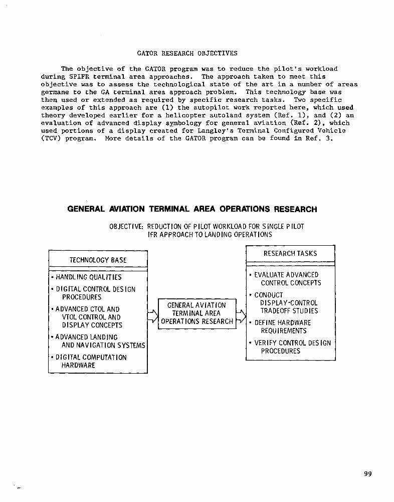
The objective of the GATOR program was to reduce the pilot's workload during SPIFR terminal area approaches. The approach taken to meet this objective was to assess the technological state of the art in a number of areas germane to the GA terminal area approach problem. This technology base was then used or extended as required by specific research tasks. Two specific examples of this approach are (1) the autopilot work reported here, which used theory developed earlier for a helicopter autoland system (Ref. l), and (2) an evaluation of advanced display symbology for general aviation (Ref. 21, which used portions of a display created for Langley's Terminal Configured Vehicle (TCV) program. More details of the CATOR program can be found in Ref. 3.
GENERAL AVIATION TERMINAL AREA OPERATIONS RESEARCH
OBJECTIVE: REDUCTION OF PILOT WORKLOAD FOR SiNGLE PILOT IFRAPPROACHTOLANDING OPERATIONS
TECHNOLOGY BASE -1
*HANDLINGQUALITIES I
l DIGITALCONTROL DESIGN PROCEDURES
.ADVANCEDCTOLAND VTOLCONTROLAND DISPLAYCONCEPTS
TERMINAL AREA OPERATIONS RESEARCH
.ADVANCED LANDING AND NAVIGATION SYSTEMS
.DIGlTALCOMPUTATION HARDWARE
RESEARCHTASKS
. EVALUATE ADVANCED CONTROLCONCEPTS
l CONDUCT DISPLAY-CONTROL TRADEOFF STUDIES
l DEFINE HARDWARE REQUIREMENTS
l VERIFY CONTROL DESIGN PROCEDURES
99
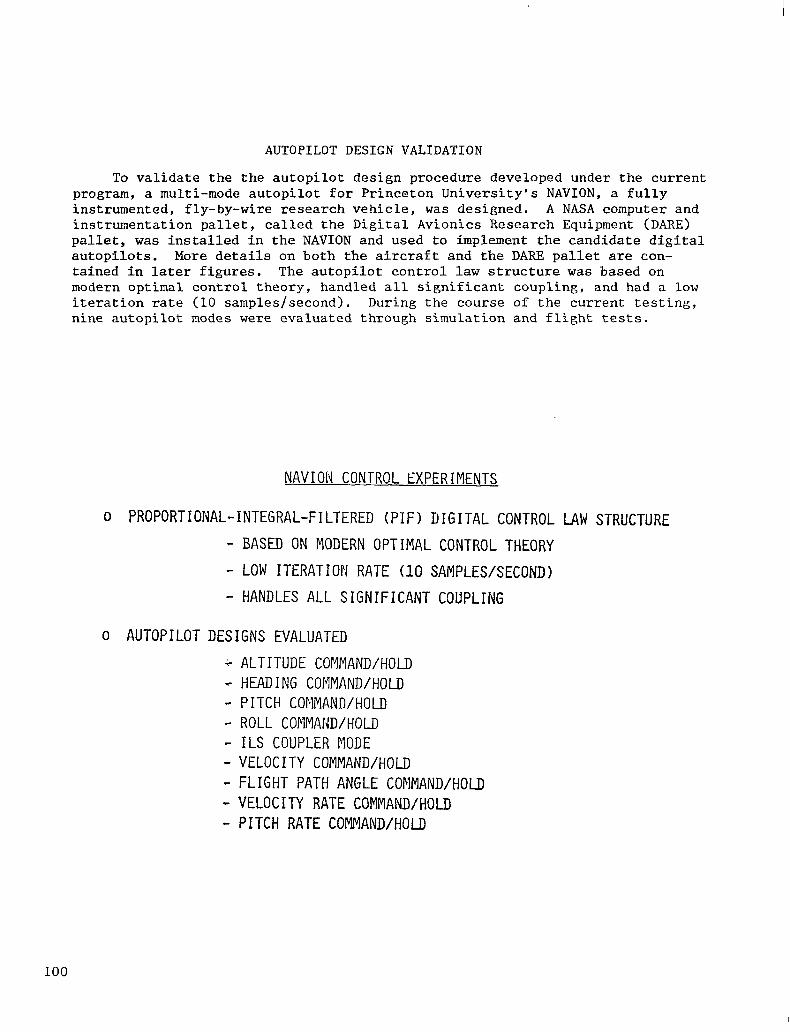
AUTOPILOT DESIGN VALIDATION
To validate the the autopilot design procedure developed under the current program, a multi-mode autopilot for Princeton University's NAVION, a fully instrumented, fly-by-wire research vehicle, was designed. A NASA computer and instrumentation pallet, called the Digital Avionics Research Equipment (DARE) pallet, was installed in the NAVION and used to implement the candidate digital autopilots. More details on both the aircraft and the DARE pallet are con- tained in later figures. The autopilot control law structure was based on modern optimal control theory, handled all significant coupling, and had a low iteration rate (10 samples/second). During the course of the current testing, nine autopilot modes were evaluated through simulation and flight tests.
NAVION CONTROL EXPERIMENTS
o PROPORTIONAL-INTEGRAL-FILTERED (PIF) DIGITAL CONTROL LAW STRUCTURE
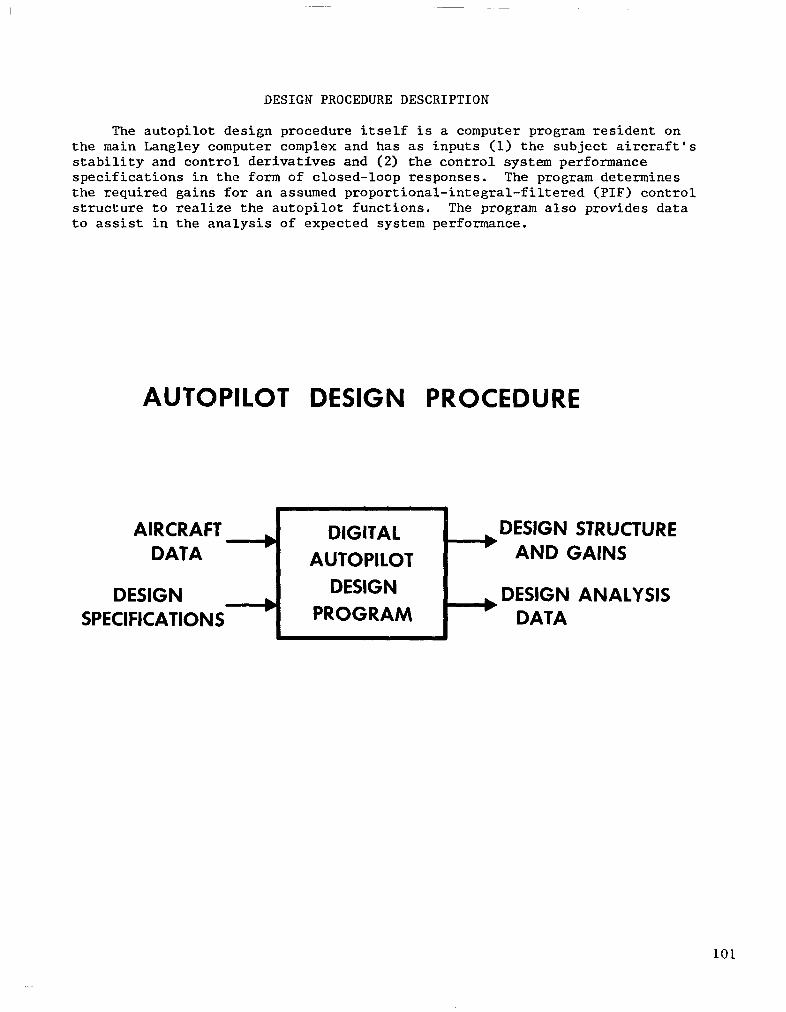
The autopilot design procedure itself is a computer program resident on the main Langley computer complex and has as inputs (1) the subject aircraft's stability and control derivatives and (2) the control system performance specifications in the form of closed-loop responses. The program determines the required gains for an assumed proportional-integral-filtered (PIF) control structure to realize the autopilot functions. The program also provides data to assist in the analysis of expected system performance.
AUTOPILOT DESIGN PROCEDURE
AIRCRAFT DATA
DESIGN SPECIFICATIONS
b DIGITAL DESIGN STRUCTURE ’ AUTOPILOT AND GAINS
DESIGN b DESIGN ANALYSIS
PROGRAM ’ DATA
101
PROPORTIONAL-INTEGRAL-FILTERED (PIF) ALGORITHM
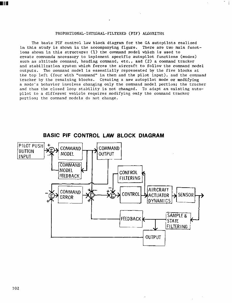
The basic PIF control law block diagram for the GA autopilots realized in this study is shown in the accompanying figure. There are two main funct- ions shown in this structure: (1) the command model which is used to create commands necessary to implement specific autopilot functions (modes) such as altitude command, heading command, etc., and (2) a command tracker and stabilization system which forces the aircraft to follow the command model outputs. The command model is essentially represented by the five blocks at the top left (four with "command" in them and the pilot input), and the command tracker by the remaining blocks. Creating a new autopilot mode or modifying a mode's behavior involves changing only the command model portion; the tracker and thus the closed loop stability is not changed. To adapt an existing auto- pilot to a different vehicle requires modifying only the command tracker portion; the command models do not change.
BASIC PIF CONTROL LAW BLOCK DIAGRAM
In” ^T PUSH + ?\I Ld r COMMAND COMMAND
IDEL OUTPUT
-lIr~ MMAND]
HI KLKHFT
‘ACTUATOR + SENSOR -+ DYNAMICS.
I FlLltKlNb 1
OUTPUT
102
RESEARCH FLIGHT SYSTEM
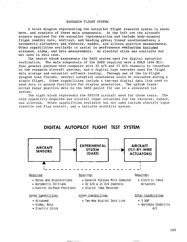
A block diagram representing the autopilot flight research system is shown here, and consists of three main components. At the left are the aircraft sensors required for the autopilot implementation and include body-mounted flight control rate, vertical, and heading gyros; linear accelerometers; a barometric altimeter; and elevator, rudder, and aileron position measurements. Other capabilities available to assist in performance evaluation included airspeed, alpha, and beta measurements. An electric stick was available but not used in this test.
The center block represents the DARE system used for digital autopilot realization. The main components of the DARE required were a ROLM 1666 Mil- Spec general purpose mini-computer with 32 A/D and 15 D/A channels to interface to the research aircraft systems, and a digital tape recorder used for flight data storage and autopilot software loading. Through use of the in-flight program load feature, several autopilot candidates could be evaluated during a single flight. Other capabilities include a two-way digital data link used to send data to ground facilities for display generation. The uplink trans- mitted radar position data to the DARE pallet for use in a simulated ILS system.
The right block represents the NAVION aircraft used for these tests. The only capability required was electric input actuators for the elevator, rudder, and ailerons. Other capabilities available but not used include electric input throttle and flap control, and a variable stability system.
DIGITAL AUTOPILOT FLIGHT TEST SYSTEM
AIRCRAFT EXPERIMENTAL AIRCRAFT
SENSORS b SYSTEM b (FLY-BY-WIRE (DARE) ACTUATORS)
5 I I
I-,----,--,-------,------:
Required: Required: Rewired:
l Rates and Accelerations l General Purpose Mini Computer l Electric Input l Barometric Altitude l 32 A/D & 15 D/A Channels Actuators l Control Surface Positions l Digital Tape Recorder
Other Capabilities Other Capabilities Other Capabilities . Airspeed l Two-Way Digital Data Link . 5 DOF l Aloha, Beta l Variable Stability l Electric Stick A/C
103
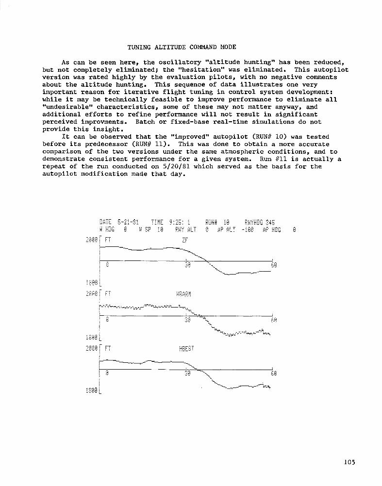
ALTITUDE COMMAND MODE PERFORMANCE
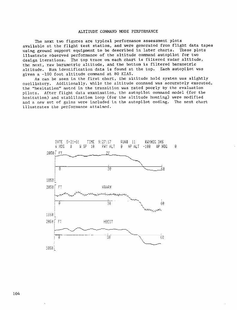
The next two figures are typical performance assessment plots available at the flight test station, and were generated from flight data tapes using ground support equipment to be described in later charts. These plots illustrate observed performance of the altitude command autopilot for two design iterations. The top trace on each chart is filtered radar altitude, the next, raw barametric altitude, and the bottom is filtered barametric altitude. Run identification data is found at the top. Each autopilot was given a -100 foot altitude command at 80 KIAS.
As can be seen in the first chart, the altitude hold system was slightly oscillatory. Additionally, while the altitude command was accurately executed, the "hesitation" noted in the transition was rated poorly by the evaluation pilots. After flight data examination, the autopilot command model (for the hesitation) and stabilization loop (for the altitude hunting) were modified and a new set of gains were included in the autopilot coding. The next chart illustrates the performance attained.
104
TUNING ALTITUDE COMMAND MODE
As can be seen here, the oscillatory "altitude hunting'* has been reduced, but not completely eliminated; the "hesitation" was eliminated. This autopilot version was rated highly by the evaluation pilots, with no negative comments about the altitude hunting. This sequence of data illustrates one very important reason for iterative flight tuning in control system development: while it may be technically feasible to improve performance to eliminate all "undesirable" characteristics, some of these may not matter anyway, and additional efforts to refine performance will not result in significant perceived improvments. Batch or fixed-base real-time simulations do not provide this insight.
It can be observed that the "improved" autopilot (RUN8 10) was tested before its predecessor (RUN!/ 11). This was done to obtain a more accurate comparison of the two versions under the same atmospheric conditions, and to demonstrate consistent performance for a given system. Run #ll is actually a repeat of the run conducted on 5/20/81 which served as the basis for the autopilot modification made that day.
105
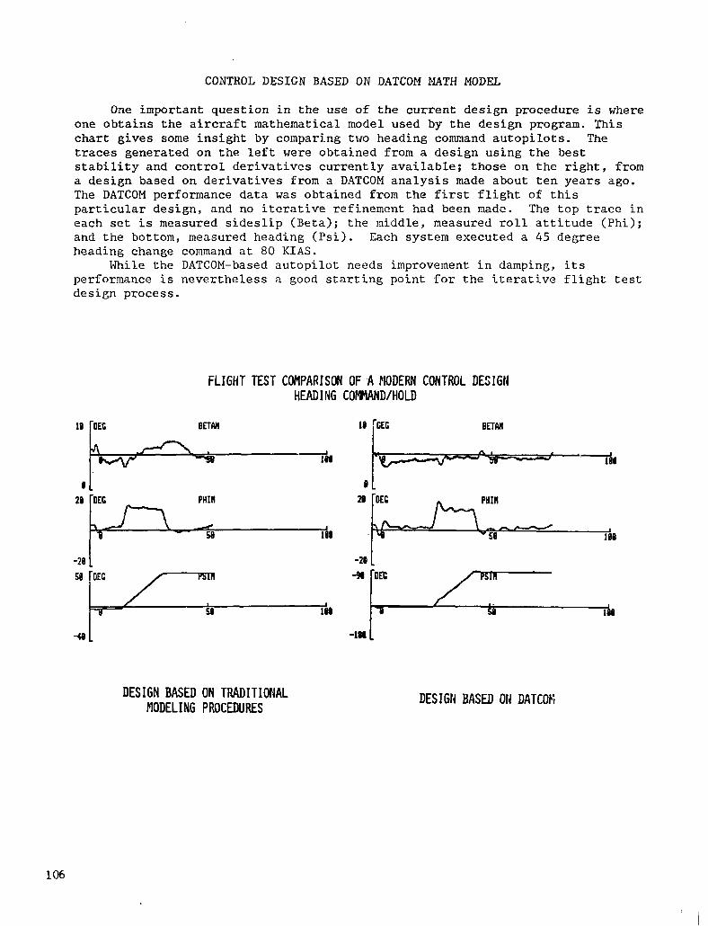
CONTROL DESIGN BASED ON DATCOM MATH MODEL
One important question in the use of the current design procedure is where one obtains the aircraft mathematical model used by the design program. This chart gives some insight by comparing two heading command autopilots. The traces generated on the left were obtained from a design using the best stability and control derivatives currently available; those on the right, from a design based on derivatives from a DATCOM analysis made about ten years ago. The DATCOM performance data was obtained from the first flight of this particular design, and no iterative refinement had been made. The top trace in each set is measured sideslip (Beta); the middle, measured roll attitude (Phi); and the bottom, measured heading (Psi). Each system executed a 45 degree heading change command at 80 KIAS.
While the DATCOM-based autopilot needs improvement in damping, its performance is nevertheless a good starting point for the iterative flight test design process.
FLIGHT TEST CONPARISLX OF -A MODERN CONTROL DESIGN HEADING COt+lAND/HOLD
DESIGN BASED ON TRADITIOFIAL 1ODELING PROCEDURES
DESIGN BASED 011 DATCOEi
106
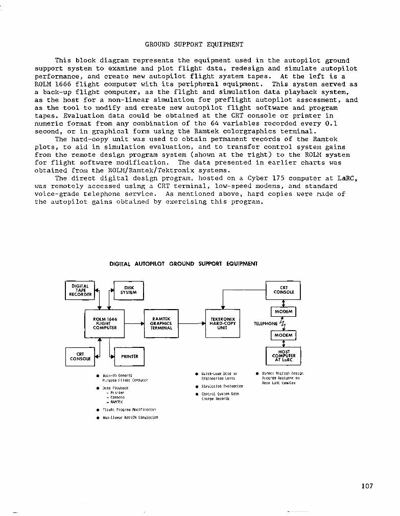
GROUND SUPPORT EQUIPMENT
This block diagram represents the equipment used in the autopilot ground support system to examine and plot flight data, redesign and simulate autopilot performance, and create new autopilot flight system tapes. At the left is a ROLM 1666 flight computer with its peripheral equipment. This system served as a back-up flight computer, as the flight and simulation data playback system, as the host for a non-linear simulation for preflight autopilot assessment, and as the tool to modify and create new autopilot flight software and program tapes. Evaluation data could be obtained at the CRT console or printer in numeric format from any combination of the 64 variables recorded every 0.1 second, or in graphical form using the Ramtek colorgraphics terminal.
The hard-copy unit was used to obtain permanent records of the Ramtek plots, to aid in simulation evaluation, and to transfer control system gains from the remote design program system (shown at the right) to the ROLM system for flight software modification. The data presented in earlier charts was obtained from the ROLM/Ramtek/Tektronix systems.
The direct digital design program, hosted on a Cyber 175 computer at LaRC, was remotely accessed using a CRT terminal, low-speed modems, and standard voice-grade telephone service. As mentioned above, hard copies were made of the autopilot gains obtained by exercising this program.
DIGITAL AUTOPILOT GROUND SUPPORT EQUIPMENT
CRT CONSOLE
ROLM 1666 RAMTEK TEKTRONIX FLIGHT -b GRAPHICS b HARD-COPY TELEPHONE
COMPUTER TERMINAL UNIT
MODEM 4 I *
. Back-UP General Pmme Fllghf COmDufer
. DotO Ploybock - Printer - Console - PAilTEK
. Quick-Look DOtO In EngIneerIn UnltS
l Slmulotlon EvaIu(ltlon
. CcmtrOl systm Gclln Change Records
l Flight Program Rodlflcotlon
. non-llnear NAVION SlmulOtlOn
107
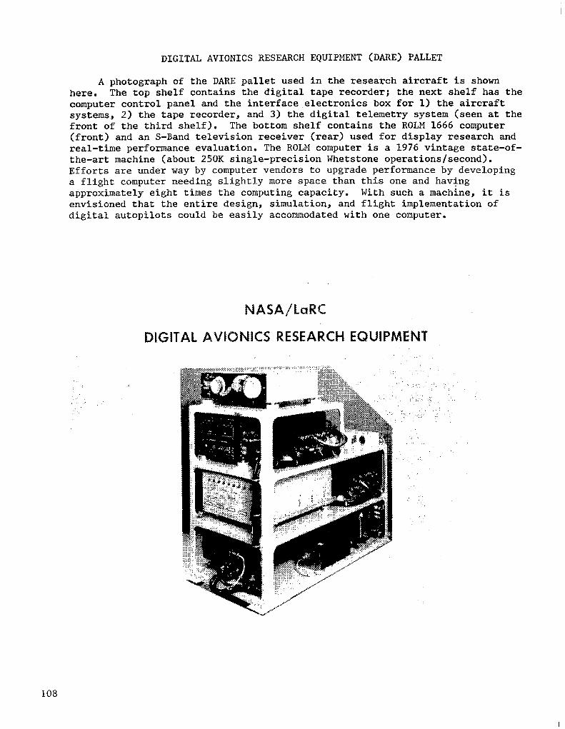
DIGITAL AVIONICS RESEARCH EQUIPMENT (DARE) PALLET
A photograph of the DARE pallet used in the research aircraft is shown here. The top shelf contains the digital tape recorder; the next shelf has the computer control panel and the interface.electronics box for 1) the aircraft systems, 2) the tape recorder, and 3) the digital telemetry system (seen at the front of the third shelf). The bottom shelf contains the ROLM 1666 computer (front) and an S-Band television receiver (rear) used for display research and real-time performance evaluation. The ROLM computer is a 1976 vintage state-of- the-art machine (about 250K single-precision Whetstone operations/second). Efforts are under way by computer vendors to upgrade performance by developing a flight computer needing slightly more space than this one and having approximately eight times the computing capacity. With such a machine, it is envisioned that the entire design, simulation, and flight implementation of digital autopilots could be easily accommodated with one computer.
NASA~l~RC
DIGITAL AVIONICS RESEARCH EQUIPMENT
108
STATUS
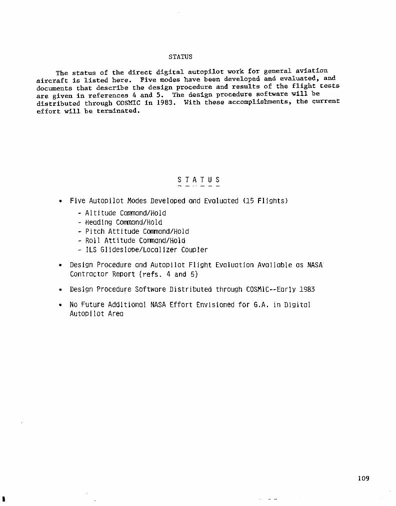
The status of the direct digital autopilot work for general aviation aircraft is listed here. Five modes have been developed and evaluated, and documents that describe the design procedure and results of the flight tests are given in references 4 and 5. The design procedure software will be distributed through COSMIC in 1983. With these accomplishments, the current effort will be terminated.
STATUS ----_-
l Five Autopilot Modes Developed and Evaluated (15 Flights) - Altitude Command/Hold
Heading Command/Hold Pitch Attitude Comand/Hold Roll Attitude Command/Hold ILS Glideslooe/Localizer Coupler
l Des ign Procedure and Autopilot Flight Evaluat Contractor Report (refs. 4 and 5)
ion Available as NASA'
l Design Procedure Software Distributed through COSMIC--Early 1983
l No Future Additional NASA Effort Envisioned for G,A, in Digital Autopilot Area
109
REFERENCES
1. Downing, D. R.; and Bryant, W. H.: "Flight Test Evaluation of a Digital Controller Used in a VTOL Automatic Approach and Landing System." Paper No. 8723, presented at the IEEE Conference on Decision and Control, Fort Lauderdale, FL, December 12-14, 1979.
2. Downing, D. R.; Bryant, W. H.; and Yenni, K. R.: "Flight Test Evaluation of Advanced Symbology for General Aviation Approach to Landing Displays." 'Paper 81-1643, presented at AIAA Aircraft Systems and Technology Meeting, Dayton, OH, August 11-13, 1981.
3. 'Downing, D. R.; Bryant, 14. H.; and Stengel, R. F.: "NASA/Princeton Digital Avionics Flight Test Facility." Presented at the 3rd Digital Avionics Systems Conference, Fort Worth, TX, November 6-8, 1979.
4. Broussard, John R.: PIFCGT - A PIF Autopilot Design Program for General Aviation Aircraft. NASA CR-166123, 1983.
5. Broussard, John R.: Design, Implementation and Flight Testing of PIF Autopilot Designs for General Aviation Aircraft, NASA CR-3709, 1983.