Digital Avionics Stack Installation & Operations Supplement Thank you for purchasing our Digital Avionics Stack and Remote Instrument Console (RIC). We utilize quality electronic components throughout the Avionics and RIC to insure years of enjoyment with little or no maintenance required. The panels/components are modular in design and are easily removed for repair or upgrade should it be required. Service and or upgrade can only be done via our service center located at our headquarters in Mather California. Please keep in mind that these are “ simulated avionics” and cannot be used in an aircraft. Although our hardware simulates aircraft avionics and is similar in design and function this supplement does not substitute for real aircraft avionics or aircraft manufactures operating principles, procedures or training. Always when using sophisticated devices such as ours you should consult approved flight instruction materials and licenced flight instructors for questions regarding proper operations. Once again thank you for being a Precision Flight Controls customer. 1
Transcript
Digital Avionics StackInstallation & Operations Supplement
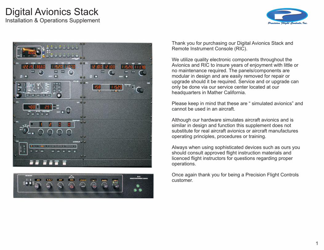
Thank you for purchasing our Digital Avionics Stack and Remote Instrument Console (RIC).
We utilize quality electronic components throughout the Avionics and RIC to insure years of enjoyment with little or no maintenance required. The panels/components are modular in design and are easily removed for repair or upgrade should it be required. Service and or upgrade can only be done via our service center located at our headquarters in Mather California.
Please keep in mind that these are “ simulated avionics” and cannot be used in an aircraft.
Although our hardware simulates aircraft avionics and is similar in design and function this supplement does notsubstitute for real aircraft avionics or aircraft manufactures operating principles, procedures or training.
Always when using sophisticated devices such as ours you should consult approved flight instruction materials and licenced flight instructors for questions regarding proper operations.
Once again thank you for being a Precision Flight Controls customer.
1
Digital Avionics StackInstallation and Setup
RICPWR12V
PWR12V
PWR XMIT
USB TOPC
SLAVE BUS FIRMWARE
UPDATE
Avionics Rear Panel
Remote Instrument Console (RIC)
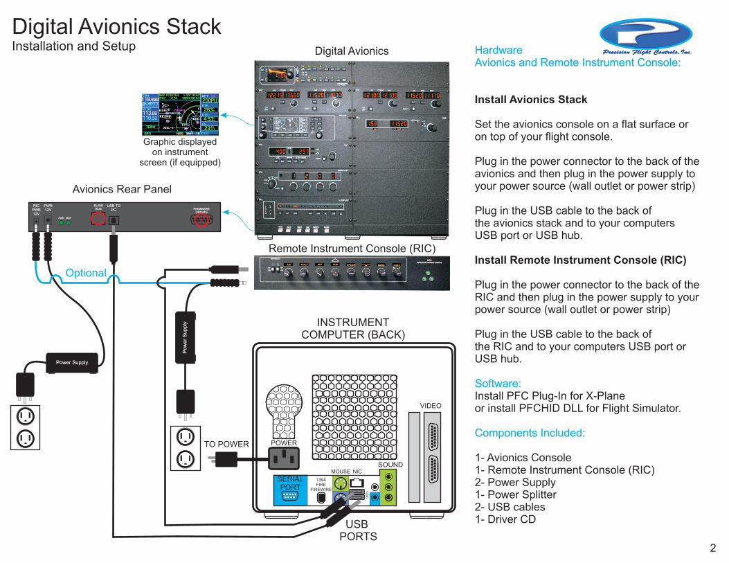
Digital Avionics HardwareAvionics and Remote Instrument Console:
Software:
Components Included:
Install Avionics Stack
Set the avionics console on a flat surface or on top of your flight console.
Plug in the power connector to the back of the avionics and then plug in the power supply to your power source (wall outlet or power strip)
Plug in the USB cable to the back ofthe avionics stack and to your computers USB port or USB hub.
Install Remote Instrument Console (RIC)
Plug in the power connector to the back of the RIC and then plug in the power supply to your power source (wall outlet or power strip)
Plug in the USB cable to the back ofthe RIC and to your computers USB port or USB hub.
Install PFC Plug-In for X-Planeor install PFCHID DLL for Flight Simulator.
1- Avionics Console1- Remote Instrument Console (RIC)2- Power Supply1- Power Splitter2- USB cables1- Driver CD
Power Supply
Po
we
r S
up
ply INSTRUMENT
COMPUTER (BACK)
VIDEO
SOUND
POWER
SERIALPORT
TO POWER
MOUSE NIC
1394FIRE
FIREWIRE
USB PORTS
Optional
2
Graphic displayedon instrument
screen (if equipped)
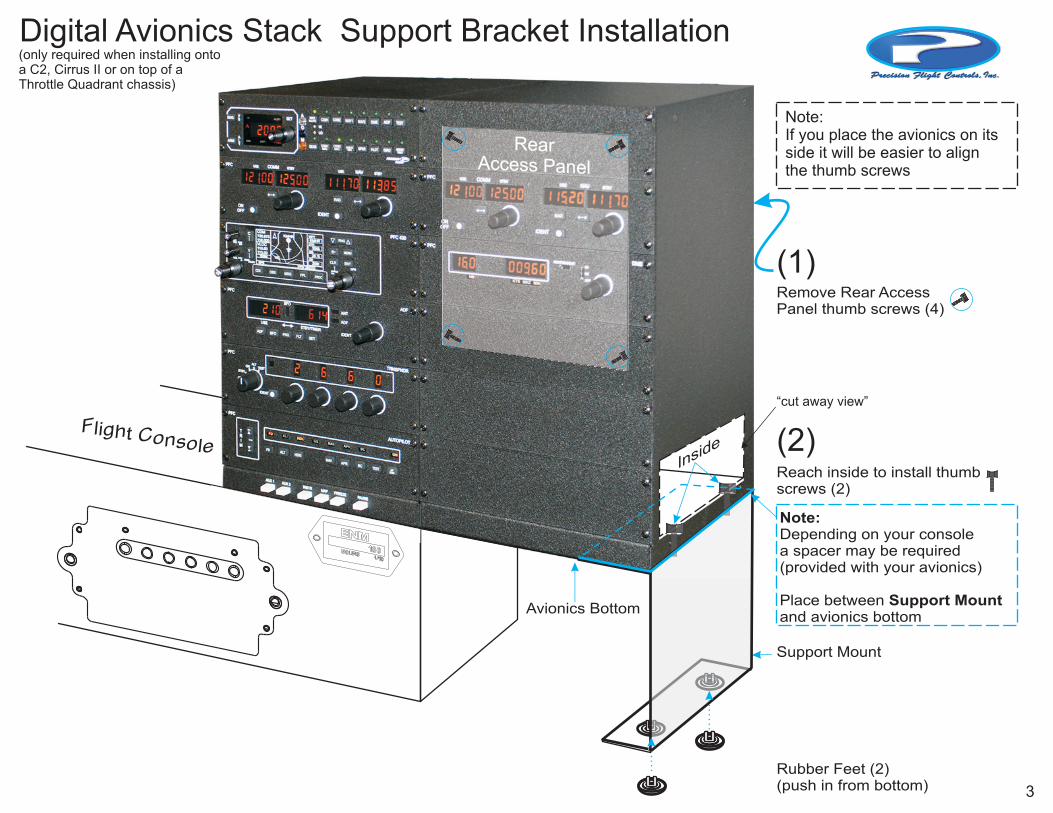
Rubber Feet (2)(push in from bottom)
Reach inside to install thumbscrews (2)
Note: Depending on your consolea spacer may be required(provided with your avionics)
Place between Support Mountand avionics bottom
Support Mount
Avionics Bottom
Remove Rear AccessPanel thumb screws (4)
Digital Avionics Stack Support Bracket Installation
i o eFl ght C nsol
(1)
(2)
Note:If you place the avionics on itsside it will be easier to alignthe thumb screws
R rea A ss ancce P el
I siden
“cut away view”
(only required when installing ontoa C2, Cirrus II or on top of a Throttle Quadrant chassis)
3
ADF ADF
VOR VOR
NAV SELECT
REMOTE INSTRUMENT CONSOLE
PUSHPUSH
A/S ADF R-ALT HDG CRS/DG BARO 1 OBS 2LDG
GEAR
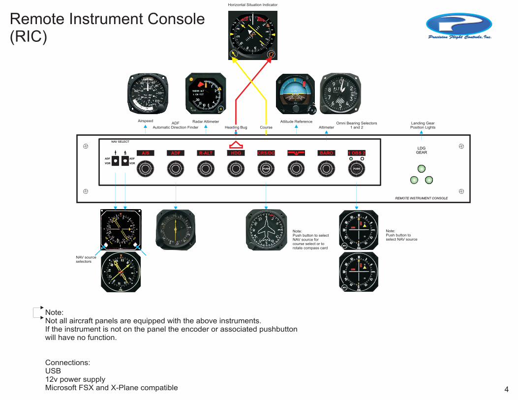
Airspeed Radar Altimeter
Heading BugADF
Automatic Direction Finder
Horizontal Situation Indicator
Course
Attitude Reference
AltimeterOmni Bearing Selectors
1 and 2Landing GearPosition Lights
Note:Not all aircraft panels are equipped with the above instruments.If the instrument is not on the panel the encoder or associated pushbuttonwill have no function.
Connections:USB12v power supplyMicrosoft FSX and X-Plane compatible
Note: Push button to select NAV source
Note: Push button to select NAV source forcourse select or torotate compass card
NAV sourceselectors
Remote Instrument Console(RIC)
4
FREEZE PAUSEMAPINSTRAUXAUX
PFCRMT/FREQ/GS/T
N1
N2
OFF
DME
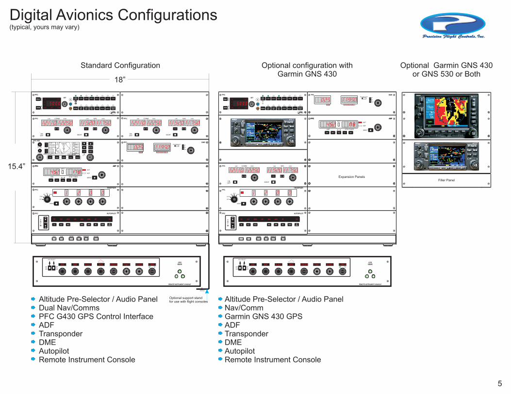
Optional support standfor use with flight consoles
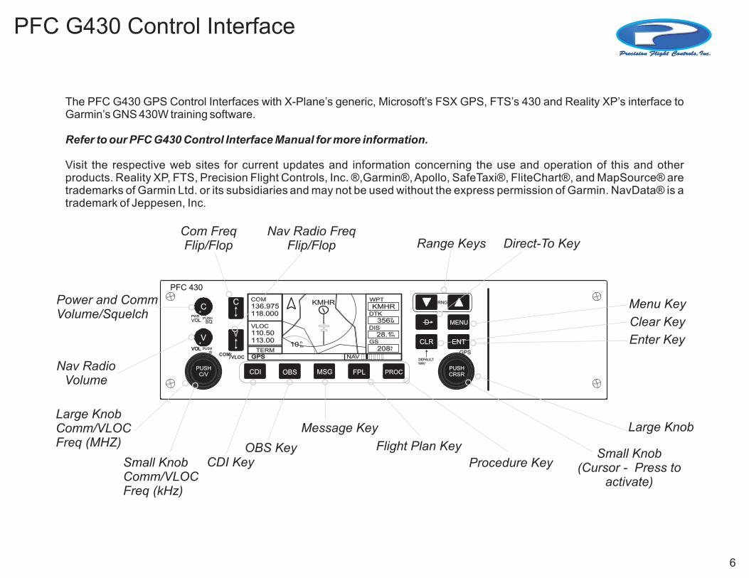
The PFC G430 GPS Control Interfaces with X-Plane’s generic, Microsoft’s FSX GPS, FTS’s 430 and Reality XP’s interface to Garmin’s GNS 430W training software.
Refer to our PFC G430 Control Interface Manual for more information.
Visit the respective web sites for current updates and information concerning the use and operation of this and other products. Reality XP, FTS, Precision Flight Controls, Inc. ®,Garmin®, Apollo, SafeTaxi®, FliteChart®, and MapSource® are trademarks of Garmin Ltd. or its subsidiaries and may not be used without the express permission of Garmin. NavData® is a
.trademark of Jeppesen, Inc
PFC 430
CDI
VOLVOL
VOL
PUSHID
PUSHSQ
PWR
MSG FPL PROCOBS
DEFAULTNAV
GPS
V V
CC
RNG
MENUD
ENTCLR
/COM VLOC GPSGPS
TERM
COM
136.975118.000
WPT
KMHRKMHR
VLOC
110.50113.00
DTK
356DIS
28.1
10 GS
208NAV
oM
nm
nm k
t
PUSHC/V
PUSHCRSR
Nav Radio Freq Flip/Flop
Com FreqFlip/Flop
Nav RadioVolume
Large KnobComm/VLOCFreq (MHZ)
Small KnobComm/VLOCFreq (kHz)
Power and CommVolume/Squelch
Range Keys Direct-To Key
Menu Key
Clear Key
Procedure Key
Flight Plan Key
Message Key
OBS KeyCDI Key
Enter Key
Large Knob
Small Knob(Cursor - Press to
activate)
PFC G430 Control Interface
6
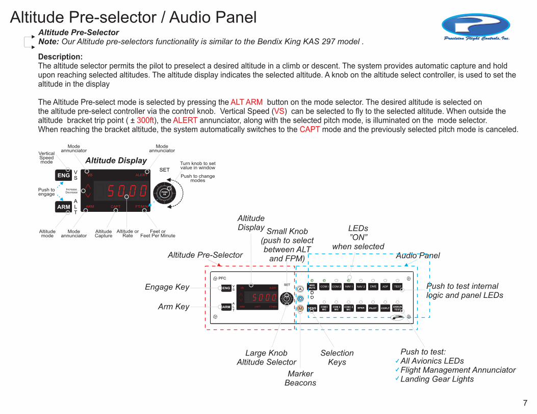
Altitude Pre-SelectorNote: Our Altitude pre-selectors functionality is similar to the Bendix King KAS 297 model .
Description: The altitude selector permits the pilot to preselect a desired altitude in a climb or descent. The system provides automatic capture and holdupon reaching selected altitudes. The altitude display indicates the selected altitude. A knob on the altitude select controller, is used to set thealtitude in the display
The Altitude Pre-select mode is selected by pressing the button on the mode selector. The desired altitude is selected onthe altitude pre-select controller via the control knob. Vertical Speed ( ) can be selected to fly to the selected altitude. When outside thealtitude bracket trip point ( ± ), the annunciator, along with the selected pitch mode, is illuminated on the mode selector. When reaching the bracket altitude, the system automatically switches to the mode and the previously selected pitch mode is canceled.
ALT ARMVS
300ft ALERT CAPT
PFC
ALERT
FT/MINCAPTARM
VS
ANNUNTEST
VS
ALT
MKRMUTE COM I COM 2 NAV I NAV 2 DME ADF TEST
COM IMIC
COM 2MIC
SPKR PILOT COPLTANNUNTESTSENS COM I 2
MIC
5 0 0 0ARM
ENGSET
PUSHVS
A
O
M
PUSHVS
Altitude Pre-Selector Audio Panel
Push to test internallogic and panel LEDs
Arm Key
MarkerBeacons
SelectionKeys
Engage Key
Small Knob(push to selectbetween ALT
and FPM)
LEDs ”ON”
when selected
Large KnobAltitude Selector
Altitude Display
Altitude Pre-selector / Audio Panel
Push to test:All Avionics LEDsFlight Management AnnunciatorLanding Gear Lights
Turn knob to setvalue in window
Push to changemodes
ALERT
FT/MINCAPTARM
VSVS
ALT
5 0 0 0ARM
ENGSET
Altitude orRate
Feet orFeet Per Minute
Push toengage
IncreaseDecrease
Vertical Speedmode
Altitudemode
AltitudeCapture
Modeannunciator
Modeannunciator
Modeannunciator
PUSHVS
PUSHVS
Altitude Display
7
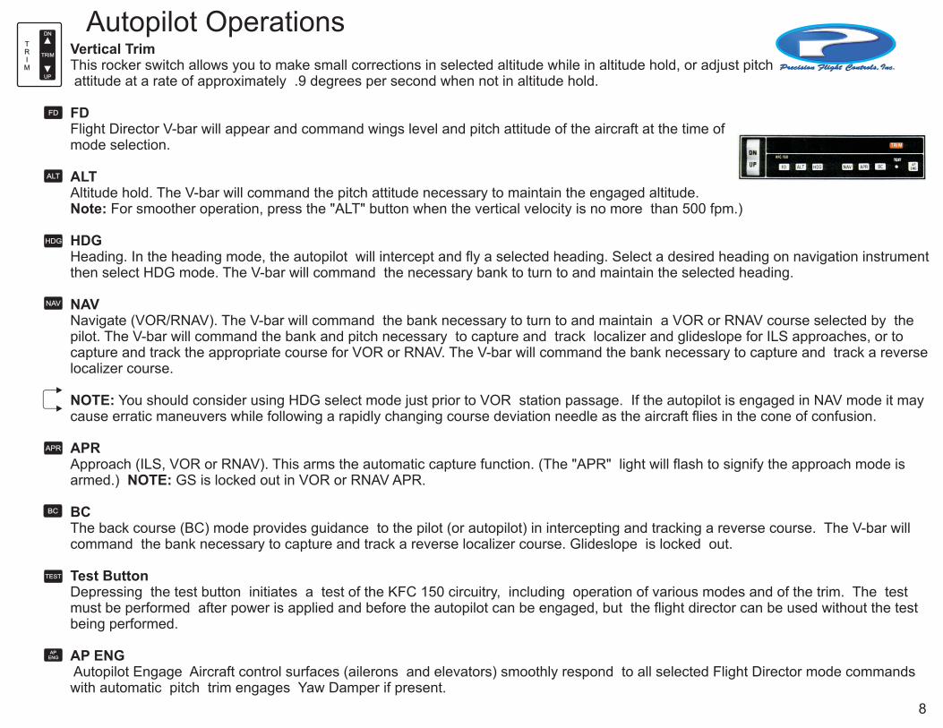
Vertical Trim This rocker switch allows you to make small corrections in selected altitude while in altitude hold, or adjust pitch attitude at a rate of approximately .9 degrees per second when not in altitude hold.
FD Flight Director V-bar will appear and command wings level and pitch attitude of the aircraft at the time of mode selection.
ALT Altitude hold. The V-bar will command the pitch attitude necessary to maintain the engaged altitude.Note: For smoother operation, press the "ALT" button when the vertical velocity is no more than 500 fpm.)
HDGHeading. In the heading mode, the autopilot will intercept and fly a selected heading. Select a desired heading on navigation instrument then select HDG mode. The V-bar will command the necessary bank to turn to and maintain the selected heading.
NAVNavigate (VOR/RNAV). The V-bar will command the bank necessary to turn to and maintain a VOR or RNAV course selected by the pilot. The V-bar will command the bank and pitch necessary to capture and track localizer and glideslope for ILS approaches, or to capture and track the appropriate course for VOR or RNAV. The V-bar will command the bank necessary to capture and track a reverse localizer course.
NOTE: You should consider using HDG select mode just prior to VOR station passage. If the autopilot is engaged in NAV mode it may cause erratic maneuvers while following a rapidly changing course deviation needle as the aircraft flies in the cone of confusion.
APRApproach (ILS, VOR or RNAV). This arms the automatic capture function. (The "APR" light will flash to signify the approach mode is armed.) NOTE: GS is locked out in VOR or RNAV APR.
BCThe back course (BC) mode provides guidance to the pilot (or autopilot) in intercepting and tracking a reverse course. The V-bar will command the bank necessary to capture and track a reverse localizer course. Glideslope is locked out.
Test Button Depressing the test button initiates a test of the KFC 150 circuitry, including operation of various modes and of the trim. The test must be performed after power is applied and before the autopilot can be engaged, but the flight director can be used without the test being performed.
AP ENG Autopilot Engage Aircraft control surfaces (ailerons and elevators) smoothly respond to all selected Flight Director mode commands with automatic pitch trim engages Yaw Damper if present.
NAV
HDG
TRIM
DN
TRIM
UP
BC
TEST
FD
ALT
APR
AP ENG
Autopilot Operations
8
Autopilot Operations
Flight Director:
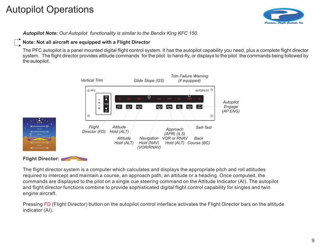
The flight director system is a computer which calculates and displays the appropriate pitch and roll attitudes required to intercept and maintain a course, an approach path, an altitude or a heading. Once computed, the commands are displayed to the pilot on a single cue steering command on the Attitude Indicator (AI). The autopilot and flight director functions combine to provide sophisticated digital flight control capability for singles and twin engine aircraft.
Pressing (Flight Director) button on the autopilot control interface activates the Flight Director bars on the attitude indicator (AI).
FD
Autopilot Note: Our Autopilot functionality is similar to the Bendix King KFC 150.
Note: Not all aircraft are equipped with a Flight Director
PFC
TRIM
AUTOPILOT
AP ENGFD NAV APRALT HDG BC TEST
FD ALT HDG GS NAV APR BC TRIM ONDN
TRIM
UP
FlightDirector (FD)
Vertical Trim Glide Slope (GS)Trim Failure Warning
(if equipped)
AltitudeHold (ALT)
AltitudeHold (ALT)
Approach(APR) (ILS)
VOR or RNAVHold (ALT)
BackCourse (BC)
Self-Test
AutopilotEngage
(AP ENG)
NavigationHold (NAV)
(VOR/RNAV)
The PFC autopilot is a panel mounted digital flight control system. It has the autopilot capability you need, plus a complete flight director system. The flight director provides attitude commands for the pilot to hand-fly, or displays to the pilot the commands being followed by the autopilot.
9
Audio Panel
PFC
ALERT
FT/MINCAPTARM
VS
ANNUNTEST
VS
ALT
MKRMUTE COM I COM 2 NAV I NAV 2 DME ADF TEST
COM IMIC
COM 2MIC
SPKR PILOT COPLTANNUNTESTSENS COM I 2
MIC
5 0 0 0ARM
ENGSET
PUSHVS
A
O
M
PUSHVS
Push to test internallogic and panel LEDs
Marker BeaconLamps
Transmitter (Audio/Mic)
Selection Buttons
SpeakerFunction Button
Pilot / Co-PilotMonitor ButtonsMarker Beacon
Receiver Sensitivity
MarkerMute
On / OffLEDS
COM 1&2
NAV1&2 DME ADF
Push to test:All Avionics LEDsFlight ManagementAnnunciatorLanding Gear Lights
PFA340
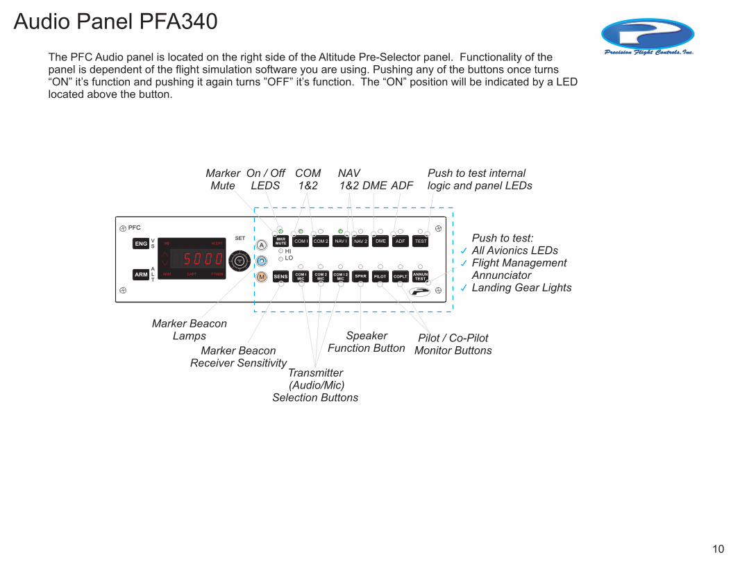
The PFC Audio panel is located on the right side of the Altitude Pre-Selector panel. Functionality of the panel is dependent of the flight simulation software you are using. Pushing any of the buttons once turns “ON” it’s function and pushing it again turns ”OFF” it’s function. The “ON” position will be indicated by a LED located above the button.
HILO
10
NAV/COMMs
COMM
Communications Navigation
ONOFF
RadioON/OFF
IdentificationButton
RadialMode
Active Frequency
Active Frequency
StandbyFrequency
StandbyFrequency
USEPFC USESTBY
IDENT
STBYNAV
NAV COMM
RAD
11 1 22 2 00 51 1 112 00 571 5
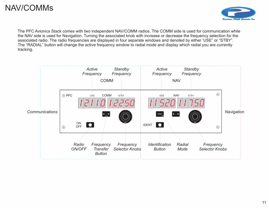
The PFC Avionics Stack comes with two independent NAV/COMM radios. The COMM side is used for communication while the NAV side is used for Navigation. Turning the associated knob with increase or decrease the frequency selection for the associated radio. The radio frequencies are displayed in four separate windows and denoted by either ‘USE” or “STBY”. The “RADIAL” button will change the active frequency window to radial mode and display which radial you are currently tracking.
FrequencySelector Knobs
FrequencySelector Knobs
FrequencyTransferButton
11
DME
PFCRMT/FREQ/GS/T
N1
N2
OFF
DME
0 2 5 11 509NM KTS MHZ MIN
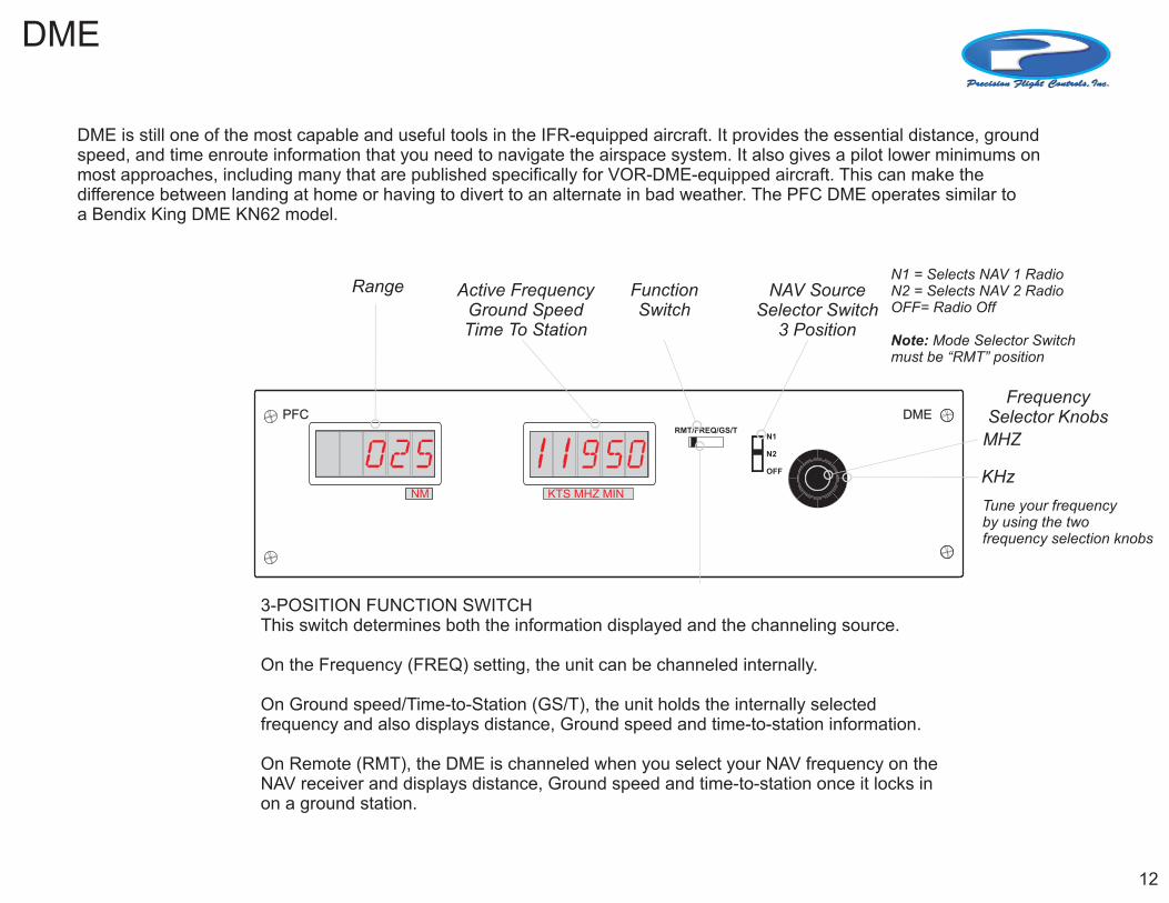
DME is still one of the most capable and useful tools in the IFR-equipped aircraft. It provides the essential distance, ground speed, and time enroute information that you need to navigate the airspace system. It also gives a pilot lower minimums on most approaches, including many that are published specifically for VOR-DME-equipped aircraft. This can make the difference between landing at home or having to divert to an alternate in bad weather. The PFC DME operates similar toa Bendix King DME KN62 model.
Active FrequencyGround SpeedTime To Station
NAV SourceSelector Switch
3 Position
FunctionSwitch
Range
FrequencySelector Knobs
MHZ
KHz
N1 = Selects NAV 1 RadioN2 = Selects NAV 2 RadioOFF= Radio Off
Note: Mode Selector Switch must be “RMT” position
3-POSITION FUNCTION SWITCH This switch determines both the information displayed and the channeling source. On the Frequency (FREQ) setting, the unit can be channeled internally.
On Ground speed/Time-to-Station (GS/T), the unit holds the internally selected frequency and also displays distance, Ground speed and time-to-station information.
On Remote (RMT), the DME is channeled when you select your NAV frequency on the NAV receiver and displays distance, Ground speed and time-to-station once it locks in on a ground station.
Tune your frequencyby using the twofrequency selection knobs
12
AD
F
ADF
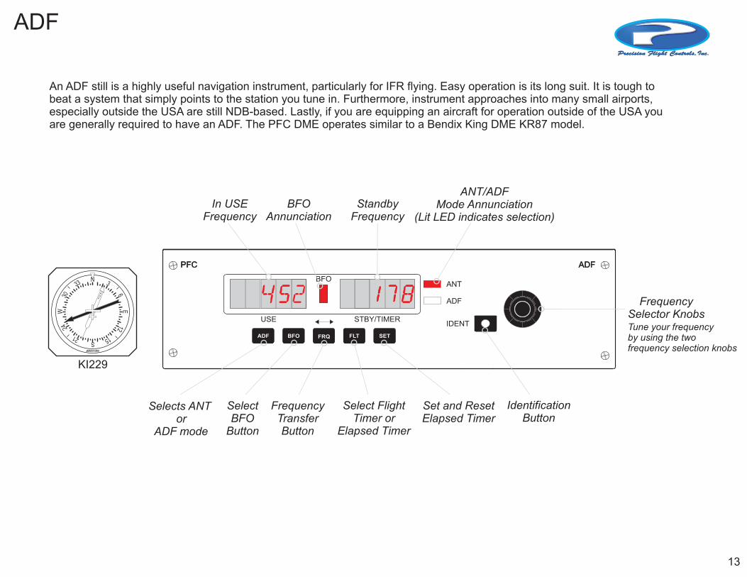
An ADF still is a highly useful navigation instrument, particularly for IFR flying. Easy operation is its long suit. It is tough to beat a system that simply points to the station you tune in. Furthermore, instrument approaches into many small airports, especially outside the USA are still NDB-based. Lastly, if you are equipping an aircraft for operation outside of the USA you are generally required to have an ADF. The PFC DME operates similar to a Bendix King DME KR87 model.
ADFADF
IDENT
ANT
ADF
PFCPFC
USE STBY/TIMER
ADFADF BFOBFO FLTFLT SETSETFRQFRQ
BFO
255 11 77 884
In USE Frequency
BFOAnnunciation
StandbyFrequency
ANT/ADFMode Annunciation
(Lit LED indicates selection)
FrequencySelector KnobsTune your frequencyby using the twofrequency selection knobs
IdentificationButton
SelectBFO
Button
FrequencyTransferButton
Set and ResetElapsed Timer
Selects ANT or
ADF mode
Select FlightTimer or
Elapsed Timer
N33
3042
21 51
126
3
W
S
E
BENDIX KING
KI229
13
TRANSPONDER
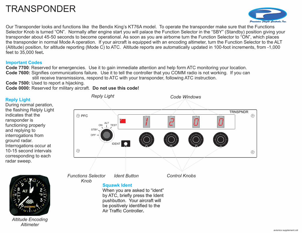
Our Transponder looks and functions like the Bendix King’s KT76A model. To operate the transponder make sure that the Functions Selector Knob is turned “ON”. Normally after engine start you will palace the Function Selector in the “SBY” (Standby) position giving your transponder about 45-50 seconds to become operational. As soon as you are airborne turn the Function Selector to “ON”, which places the transponder in normal Mode A operation. If your aircraft is equipped with an encoding altimeter, turn the Function Selector to the ALT (Altitude) position, for altitude reporting (Mode C) to ATC. Altitude reports are automatically updated in 100-foot increments, from -1,000 feet to 35,000 feet.
Code 7700: Reserved for emergencies. Use it to gain immediate attention and help form ATC monitoring your location. Code 7600: Signifies communications failure. Use it to tell the controller that you COMM radio is not working. If you can still receive transmissions, respond to ATC with your transponder, following ATC instruction.Code 7500: Used to report a hijacking.Code 0000: Reserved for military aircraft. Do not use this code!
Important Codes
PFC
IDENT
OFF
STBY
ONALT
TEST
TRNSPNDR
1 2 0 0
Functions SelectorKnob
Ident Button
Code WindowsReply Light
Control Knobs
Squawk IdentWhen you are asked to “ident” by ATC, briefly press the Ident pushbutton. Your aircraft will be positively identified to the Air Traffic Controller.
Reply LightDuring normal peration, the flashing Relply Light indicates that the ransponder is functioning properly and replying to interrogations from ground radar. Interrogations occur at 10-15 second intervals corresponding to each radar sweep.