Digital Core study of Wanaea and Perseus Core Fragments: Summary for Woodside Energy Mark A. Knackstedt 1,2 , A. Ghous 2 , C. H. Arns 1 , H. Averdunk 1 , F. Bauget 1 , A. Sakellariou 1 , T.J. Senden 1 , A.P. Sheppard 1 ,R. M. Sok 1 , and W. Val Pinczewski 2 May 12, 2004 (1) Department of Applied Mathematics, Research School of Physical Sciences and Engineering, Australian National University, Canberra ACT 0200, Australia (2) School of Petroleum Engineering, University of New South Wales, Sydney, NSW 2052, Australia Overview Fragments of 10 core plugs provided by Woodside Energy have been analysed at ANU/UNSW micro-CT facility. Here we briefly describe the work undertaken and present the primary results of the imaging, visualizing and modeling study. The experimental preparation for analysis involved choosing a small fragment of the plugs for 3D imaging. As shown in Fig. 1, a 1cm slice was taken from the cores provided, and a 6 mm x 6 mm square cross section cut from this slice. Imaging was then undertaken on this subset (1 cm x 6 mm x 6 mm) at 2000 3 with a resolution of ’ 4 - 5 μm. Further details of the experimental method are given in the attached Powerpoint file <experiment.ppt > on the attached CD. 3D movies showing serial slices through each of the cores are also provided in the attached CD. Phase separation was then undertaken on the cores to delineate the pore phase from the mineral phase. The analysis of the 10 cores is detailed in the attached file <segment.pdf >. Ideally, one would wish to have a clear bimodal distribution between the pore and mineral phase peaks. This would allow one to perform a simple differentiation of pore and solid phases. Unfortunately, the presence of pores and features below the image resolution (particulary clays) leads to ambiguity in defining the void phase. While open pores are easily obtained, clay filled pores are difficult to distinguish. In all cases, the porosity we measure is associated with the total clay-free porosity and does not include contributions from the clay or pore-cemented phases. The full overview of the phase separation methodology and results are given in the attached file <segment.pdf >. Computational results made directly from the digitized tomographic images are made for a number of pore size parameters (mean pore size, chord length, air/brine and mercury drainage capillary pressure). We then present data for the Formation factor and the permeability of the cores. From the 10 small core fragments (Volume << 1cm 3 ) we obtain over 1500 independent data points. In Fig. 2 the full set of calculated porosity:permeability (k : φ) data obtained from 1
Transcript
Digital Core study of
Wanaea and Perseus Core Fragments:Summary for Woodside Energy
Mark A. Knackstedt1,2, A. Ghous2, C. H. Arns1, H. Averdunk1, F. Bauget1,A. Sakellariou1, T.J. Senden1, A.P. Sheppard1,R. M. Sok1, and W. Val Pinczewski2
May 12, 2004
(1) Department of Applied Mathematics, Research School of Physical Sciences andEngineering,
Australian National University, Canberra ACT 0200, Australia(2) School of Petroleum Engineering, University of New South Wales,
Sydney, NSW 2052, Australia
Overview
Fragments of 10 core plugs provided by Woodside Energy have been analysed at ANU/UNSWmicro-CT facility. Here we briefly describe the work undertaken and present the primary resultsof the imaging, visualizing and modeling study.
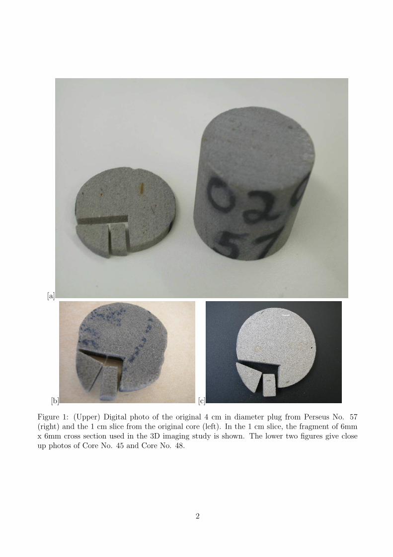
The experimental preparation for analysis involved choosing a small fragment of the plugsfor 3D imaging. As shown in Fig. 1, a 1cm slice was taken from the cores provided, and a6 mm x 6 mm square cross section cut from this slice. Imaging was then undertaken on thissubset (1 cm x 6 mm x 6 mm) at 20003 with a resolution of ' 4 − 5 µm. Further details ofthe experimental method are given in the attached Powerpoint file <experiment.ppt> on theattached CD. 3D movies showing serial slices through each of the cores are also provided in theattached CD.
Phase separation was then undertaken on the cores to delineate the pore phase from themineral phase. The analysis of the 10 cores is detailed in the attached file <segment.pdf >.Ideally, one would wish to have a clear bimodal distribution between the pore and mineralphase peaks. This would allow one to perform a simple differentiation of pore and solid phases.Unfortunately, the presence of pores and features below the image resolution (particulary clays)leads to ambiguity in defining the void phase. While open pores are easily obtained, clay filledpores are difficult to distinguish. In all cases, the porosity we measure is associated with the totalclay-free porosity and does not include contributions from the clay or pore-cemented phases.The full overview of the phase separation methodology and results are given in the attached file<segment.pdf >.
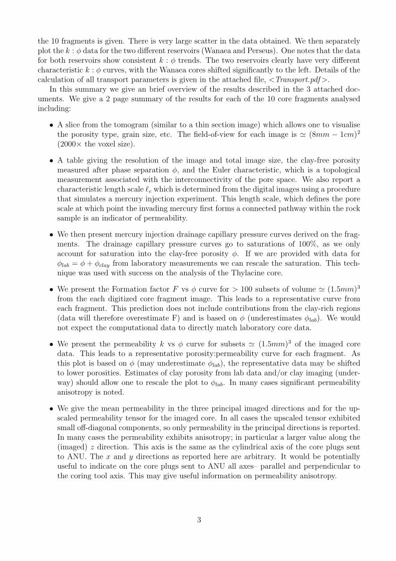
Computational results made directly from the digitized tomographic images are made for anumber of pore size parameters (mean pore size, chord length, air/brine and mercury drainagecapillary pressure). We then present data for the Formation factor and the permeability of thecores. From the 10 small core fragments (Volume << 1cm3) we obtain over 1500 independentdata points. In Fig. 2 the full set of calculated porosity:permeability (k : φ) data obtained from
1
[a]
[b] [c]
Figure 1: (Upper) Digital photo of the original 4 cm in diameter plug from Perseus No. 57(right) and the 1 cm slice from the original core (left). In the 1 cm slice, the fragment of 6mmx 6mm cross section used in the 3D imaging study is shown. The lower two figures give closeup photos of Core No. 45 and Core No. 48.
2
the 10 fragments is given. There is very large scatter in the data obtained. We then separatelyplot the k : φ data for the two different reservoirs (Wanaea and Perseus). One notes that the datafor both reservoirs show consistent k : φ trends. The two reservoirs clearly have very differentcharacteristic k : φ curves, with the Wanaea cores shifted significantly to the left. Details of thecalculation of all transport parameters is given in the attached file, <Transport.pdf >.
In this summary we give an brief overview of the results described in the 3 attached doc-uments. We give a 2 page summary of the results for each of the 10 core fragments analysedincluding:
• A slice from the tomogram (similar to a thin section image) which allows one to visualisethe porosity type, grain size, etc. The field-of-view for each image is ' (8mm − 1cm)2
(2000× the voxel size).
• A table giving the resolution of the image and total image size, the clay-free porositymeasured after phase separation φ, and the Euler characteristic, which is a topologicalmeasurement associated with the interconnectivity of the pore space. We also report acharacteristic length scale `c which is determined from the digital images using a procedurethat simulates a mercury injection experiment. This length scale, which defines the porescale at which point the invading mercury first forms a connected pathway within the rocksample is an indicator of permeability.
• We then present mercury injection drainage capillary pressure curves derived on the frag-ments. The drainage capillary pressure curves go to saturations of 100%, as we onlyaccount for saturation into the clay-free porosity φ. If we are provided with data forφlab = φ + φclay from laboratory measurements we can rescale the saturation. This tech-nique was used with success on the analysis of the Thylacine core.
• We present the Formation factor F vs φ curve for > 100 subsets of volume ' (1.5mm)3
from the each digitized core fragment image. This leads to a representative curve fromeach fragment. This prediction does not include contributions from the clay-rich regions(data will therefore overestimate F) and is based on φ (underestimates φlab). We wouldnot expect the computational data to directly match laboratory core data.
• We present the permeability k vs φ curve for subsets ' (1.5mm)3 of the imaged coredata. This leads to a representative porosity:permeability curve for each fragment. Asthis plot is based on φ (may underestimate φlab), the representative data may be shiftedto lower porosities. Estimates of clay porosity from lab data and/or clay imaging (under-way) should allow one to rescale the plot to φlab. In many cases significant permeabilityanisotropy is noted.
• We give the mean permeability in the three principal imaged directions and for the up-scaled permeability tensor for the imaged core. In all cases the upscaled tensor exhibitedsmall off-diagonal components, so only permeability in the principal directions is reported.In many cases the permeability exhibits anisotropy; in particular a larger value along the(imaged) z direction. This axis is the same as the cylindrical axis of the core plugs sentto ANU. The x and y directions as reported here are arbitrary. It would be potentiallyuseful to indicate on the core plugs sent to ANU all axes– parallel and perpendicular tothe coring tool axis. This may give useful information on permeability anisotropy.
Figure 2: (Top) Plot of Permeability: φ correlation for all 10 core fragments analysed. (Bottomleft) Plot of Permeability: φ correlation for the 4 core fragments from the Wanaea reservoir and(right), plot of Permeability: φ correlation for the 6 core fragments from the Perseus reservoir.Considered separately, the data for the two reservoirs show consistent k : φ trends.
4
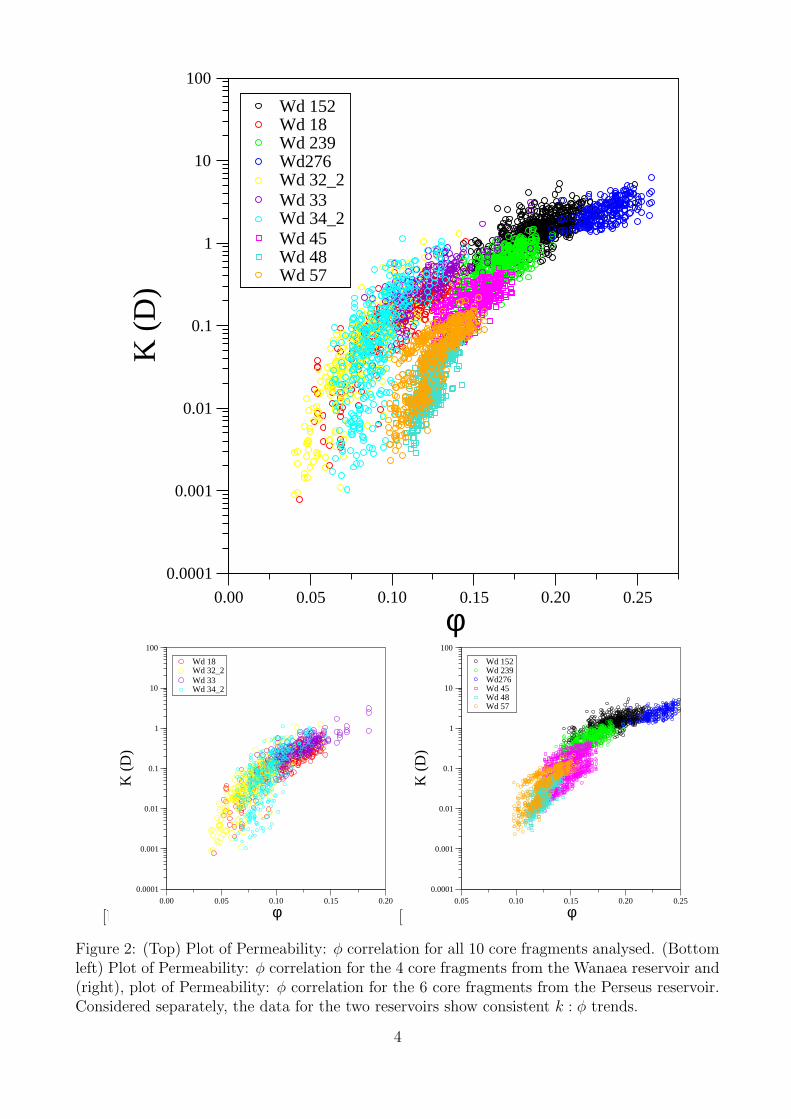
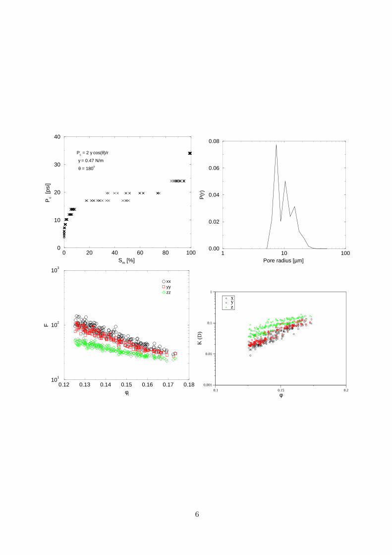
1 Perseus Plug No. 45
The slice of the tomogram shows a small range of grain sizes and a small degree of clay foulingof the pores. The grain shapes are less rounded and have low sphericity leading to regionswith quite tight pores. The Euler characteristic is very large indicating a highly interconnectedporosity, and the value of the characteristic pore radius is `c = 6.8µm. The capillary pressurecurve shows a distinct long flat region, indicating a reasonably narrow pore size distribution.The F : φ plot shows little scatter, has rather strong anisotropy and exhibits values 20 < F <
200. One also observes a strong anisotropy (factor 2 times) with higher conductance in thez direction. The permeability plot shows a strong anisotropy. The mean (k̄) and upscaled(kupscale) permeabilities also exhibit this anisotropy.
k̄(x, y, z) = (92, 84, 166) mDkupscale(x, y, z) = (62, 78, 148) mD
4.022 µm 960 x 1056 x 1800 14.3% -1707 6.8 µm ±0.8
5
0 20 40 60 80 100Sm [%]
0
10
20
30
40
Pc
[psi
]
Pc = 2 γ cos(θ)/r
γ = 0.47 N/m
θ = 180o
1 10 100Pore radius [µm]
0.00
0.02
0.04
0.06
0.08
P(r
)
0.12 0.13 0.14 0.15 0.16 0.17 0.18φt
101
102
103
F
xxyyzz
0.1 0.15 0.2
φ
0.001
0.01
0.1
1
K (
D)
xyz
6
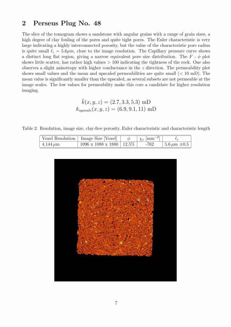
2 Perseus Plug No. 48
The slice of the tomogram shows a sandstone with angular grains with a range of grain sizes, ahigh degree of clay fouling of the pores and quite tight pores. The Euler characteristic is verylarge indicating a highly interconnected porosity, but the value of the characteristic pore radiusis quite small `c = 5.6µm, close to the image resolution. The Capillary pressure curve showsa distinct long flat region, giving a narrow equivalent pore size distribution. The F : φ plotshows little scatter, has rather high values > 100 indicating the tightness of the rock. One alsoobserves a slight anisotropy with higher conductance in the z direction. The permeability plotshows small values and the mean and upscaled permeabilities are quite small (< 10 mD). Themean value is significantly smaller than the upscaled, as several subsets are not permeable at theimage scales. The low values for permeability make this core a candidate for higher resolutionimaging.
k̄(x, y, z) = (2.7, 3.3, 5.3) mDkupscale(x, y, z) = (6.9, 9.1, 11) mD
4.144 µm 1096 x 1088 x 1880 12.5% -762 5.6 µm ±0.5
7
0 20 40 60 80 100Sm [%]
0
10
20
30
40
Pc
[psi
]
Pc = 2 γ cos(θ)/r
γ = 0.47 N/m
θ = 180o
1 10 100 1000Pore radius [µm]
0.00
0.02
0.04
0.06
0.08
0.10
P(r
)
0.10 0.11 0.12 0.13 0.14 0.15φt
101
102
103
104
F
xxyyzz
0.1 0.12 0.14
φ
0.1
1
10
100
K (
mD
)
xyz
8
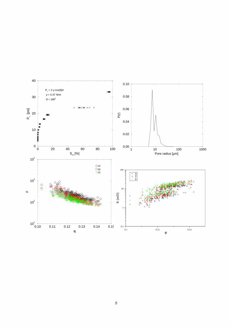
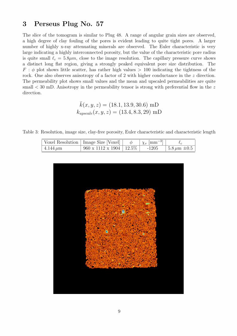
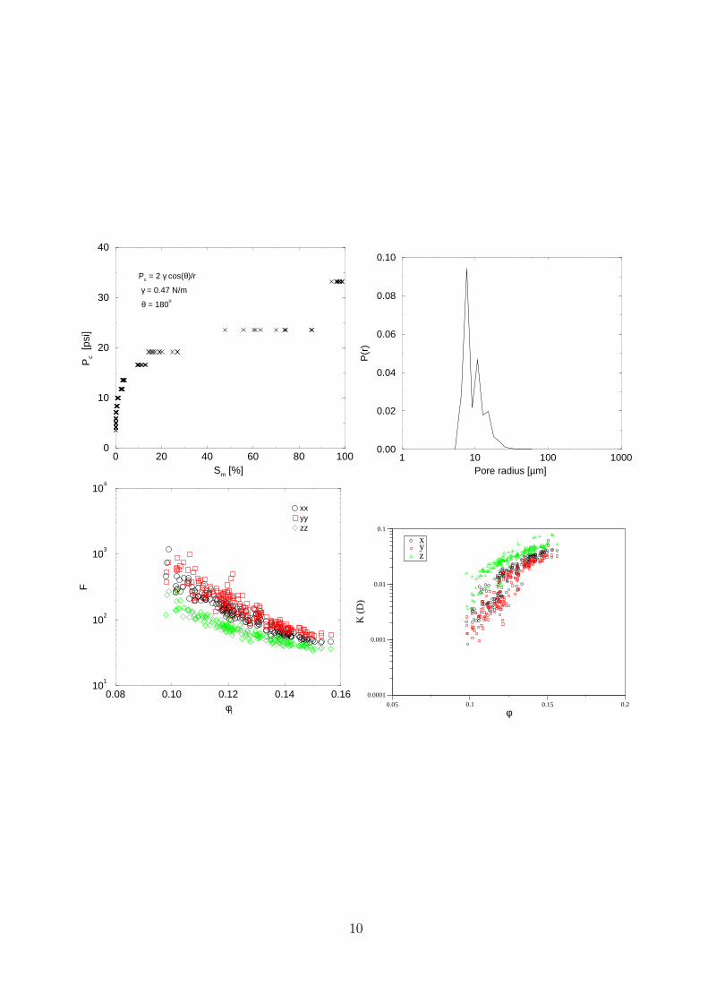
3 Perseus Plug No. 57
The slice of the tomogram is similar to Plug 48. A range of angular grain sizes are observed,a high degree of clay fouling of the pores is evident leading to quite tight pores. A largernumber of highly x-ray attenuating minerals are observed. The Euler characteristic is verylarge indicating a highly interconnected porosity, but the value of the characteristic pore radiusis quite small `c = 5.8µm, close to the image resolution. The capillary pressure curve showsa distinct long flat region, giving a strongly peaked equivalent pore size distribution. TheF : φ plot shows little scatter, has rather high values > 100 indicating the tightness of therock. One also observes anisotropy of a factor of 2 with higher conductance in the z direction.The permeability plot shows small values and the mean and upscaled permeabilities are quitesmall < 30 mD. Anisotropy in the permeability tensor is strong with preferential flow in the z
direction.
k̄(x, y, z) = (18.1, 13.9, 30.6) mDkupscale(x, y, z) = (13.4, 8.3, 29) mD
4.144 µm 960 x 1112 x 1904 12.5% -1205 5.8 µm ±0.5
9
0 20 40 60 80 100Sm [%]
0
10
20
30
40
Pc
[psi
]
Pc = 2 γ cos(θ)/r
γ = 0.47 N/m
θ = 180o
1 10 100 1000Pore radius [µm]
0.00
0.02
0.04
0.06
0.08
0.10
P(r
)
0.08 0.10 0.12 0.14 0.16φt
101
102
103
104
F
xxyyzz
0.05 0.1 0.15 0.2
φ
0.0001
0.001
0.01
0.1
K (
D)
xyz
10
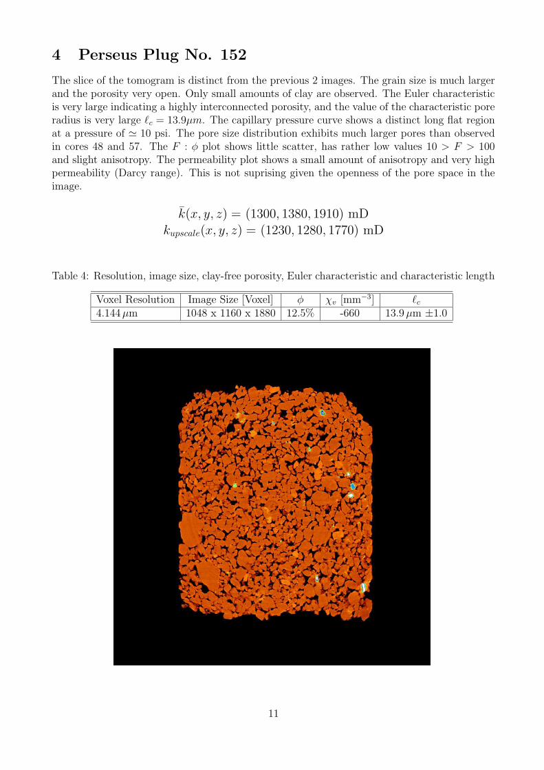
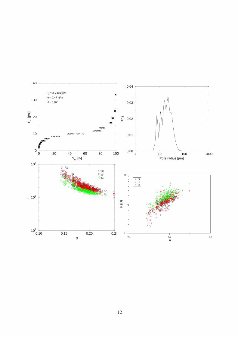
4 Perseus Plug No. 152
The slice of the tomogram is distinct from the previous 2 images. The grain size is much largerand the porosity very open. Only small amounts of clay are observed. The Euler characteristicis very large indicating a highly interconnected porosity, and the value of the characteristic poreradius is very large `c = 13.9µm. The capillary pressure curve shows a distinct long flat regionat a pressure of ' 10 psi. The pore size distribution exhibits much larger pores than observedin cores 48 and 57. The F : φ plot shows little scatter, has rather low values 10 > F > 100and slight anisotropy. The permeability plot shows a small amount of anisotropy and very highpermeability (Darcy range). This is not suprising given the openness of the pore space in theimage.
k̄(x, y, z) = (1300, 1380, 1910) mDkupscale(x, y, z) = (1230, 1280, 1770) mD
4.144 µm 1048 x 1160 x 1880 12.5% -660 13.9 µm ±1.0
11
0 20 40 60 80 100Sm [%]
0
10
20
30
40
Pc
[psi
]
Pc = 2 γ cos(θ)/r
γ = 0.47 N/m
θ = 180o
1 10 100 1000Pore radius [µm]
0.00
0.01
0.02
0.03
0.04
P(r
)
0.10 0.15 0.20 0.25φt
100
101
102
F
xxyyzz
0.1 0.2 0.3
φ
0.1
1
10
K (
D)
xyz
12
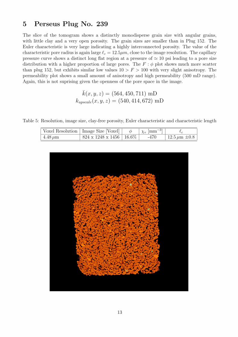
5 Perseus Plug No. 239
The slice of the tomogram shows a distinctly monodisperse grain size with angular grains,with little clay and a very open porosity. The grain sizes are smaller than in Plug 152. TheEuler characteristic is very large indicating a highly interconnected porosity. The value of thecharacteristic pore radius is again large `c = 12.5µm, close to the image resolution. The capillarypressure curve shows a distinct long flat region at a pressure of ' 10 psi leading to a pore sizedistribution with a higher proportion of large pores. The F : φ plot shows much more scatterthan plug 152, but exhibits similar low values 10 > F > 100 with very slight anisotropy. Thepermeability plot shows a small amount of anisotropy and high permeability (500 mD range).Again, this is not suprising given the openness of the pore space in the image.
k̄(x, y, z) = (564, 450, 711) mDkupscale(x, y, z) = (540, 414, 672) mD
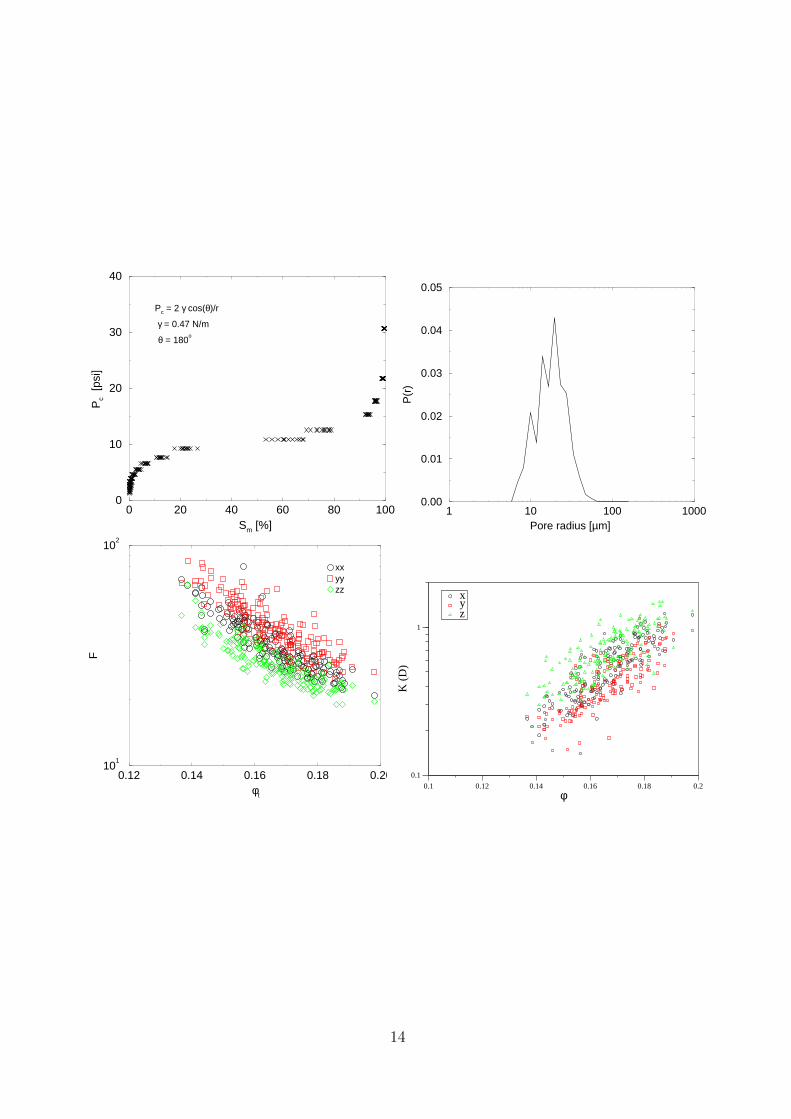
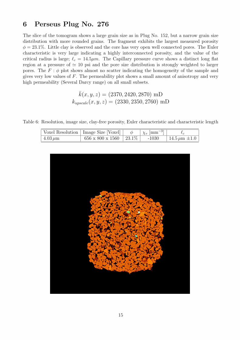
The slice of the tomogram shows a large grain size as in Plug No. 152, but a narrow grain sizedistribution with more rounded grains. The fragment exhibits the largest measured porosityφ = 23.1%. Little clay is observed and the core has very open well connected pores. The Eulercharacteristic is very large indicating a highly interconnected porosity, and the value of thecritical radius is large; `c = 14.5µm. The Capillary pressure curve shows a distinct long flatregion at a pressure of ' 10 psi and the pore size distribution is strongly weighted to largerpores. The F : φ plot shows almost no scatter indicating the homogeneity of the sample andgives very low values of F . The permeability plot shows a small amount of anisotropy and veryhigh permeability (Several Darcy range) on all small subsets.
k̄(x, y, z) = (2370, 2420, 2870) mDkupscale(x, y, z) = (2330, 2350, 2760) mD
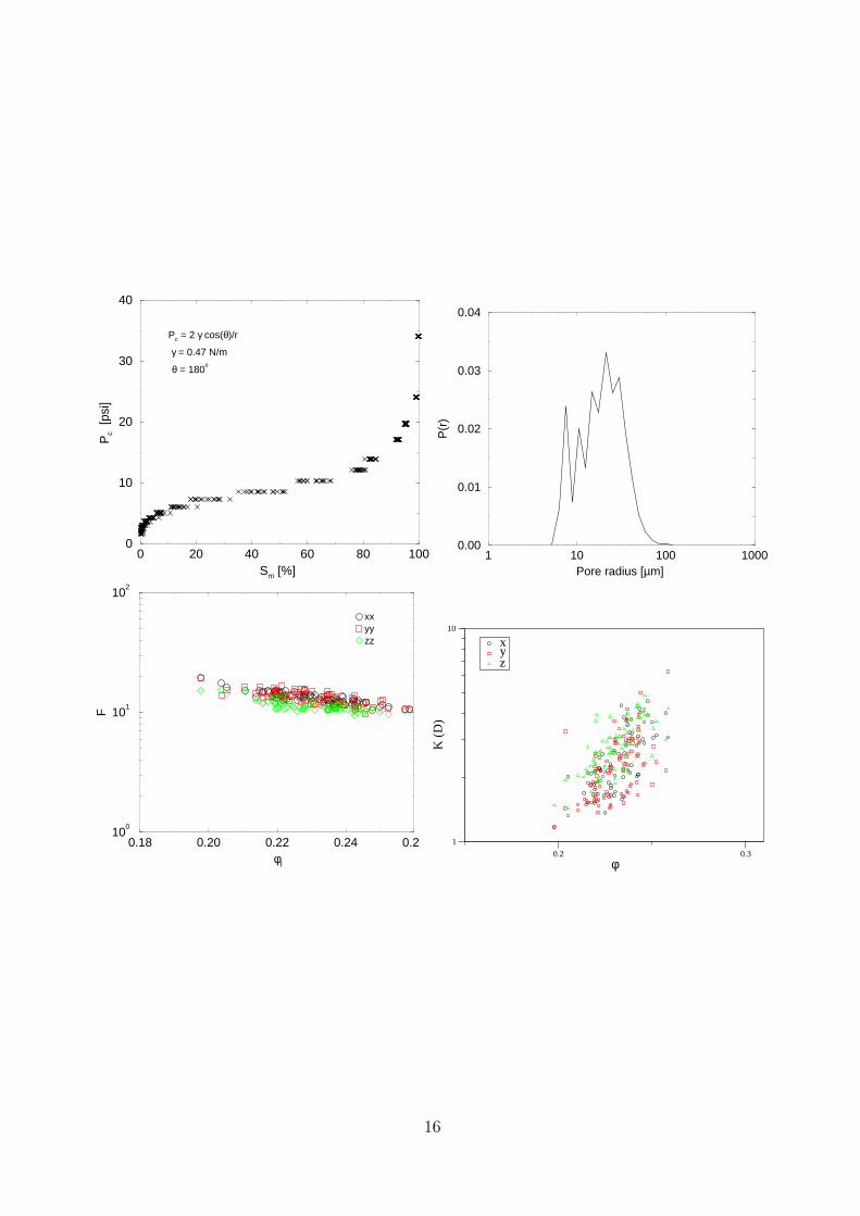
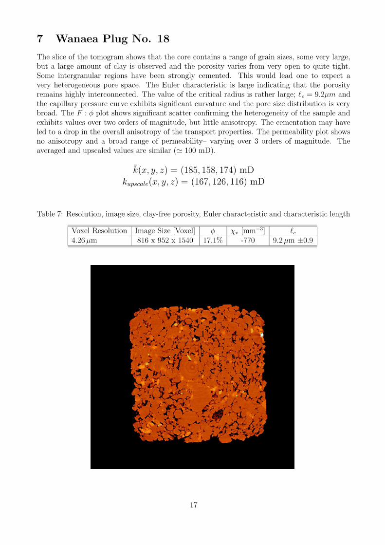
The slice of the tomogram shows that the core contains a range of grain sizes, some very large,but a large amount of clay is observed and the porosity varies from very open to quite tight.Some intergranular regions have been strongly cemented. This would lead one to expect avery heterogeneous pore space. The Euler characteristic is large indicating that the porosityremains highly interconnected. The value of the critical radius is rather large; `c = 9.2µm andthe capillary pressure curve exhibits significant curvature and the pore size distribution is verybroad. The F : φ plot shows significant scatter confirming the heterogeneity of the sample andexhibits values over two orders of magnitude, but little anisotropy. The cementation may haveled to a drop in the overall anisotropy of the transport properties. The permeability plot showsno anisotropy and a broad range of permeability– varying over 3 orders of magnitude. Theaveraged and upscaled values are similar (' 100 mD).
k̄(x, y, z) = (185, 158, 174) mDkupscale(x, y, z) = (167, 126, 116) mD
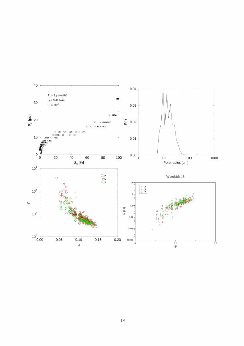
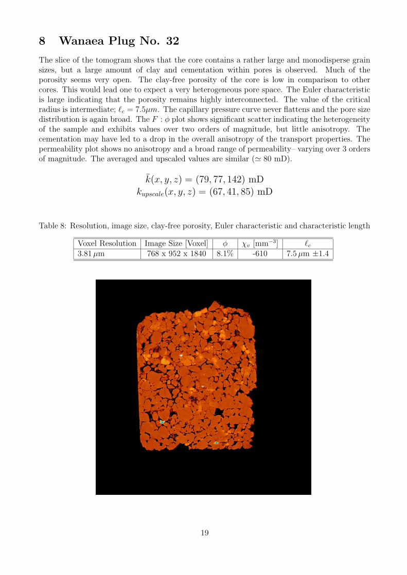
The slice of the tomogram shows that the core contains a rather large and monodisperse grainsizes, but a large amount of clay and cementation within pores is observed. Much of theporosity seems very open. The clay-free porosity of the core is low in comparison to othercores. This would lead one to expect a very heterogeneous pore space. The Euler characteristicis large indicating that the porosity remains highly interconnected. The value of the criticalradius is intermediate; `c = 7.5µm. The capillary pressure curve never flattens and the pore sizedistribution is again broad. The F : φ plot shows significant scatter indicating the heterogeneityof the sample and exhibits values over two orders of magnitude, but little anisotropy. Thecementation may have led to a drop in the overall anisotropy of the transport properties. Thepermeability plot shows no anisotropy and a broad range of permeability– varying over 3 ordersof magnitude. The averaged and upscaled values are similar (' 80 mD).
k̄(x, y, z) = (79, 77, 142) mDkupscale(x, y, z) = (67, 41, 85) mD
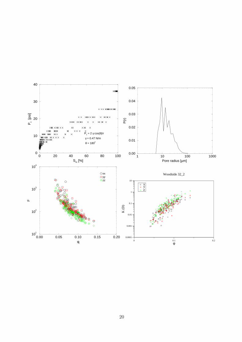
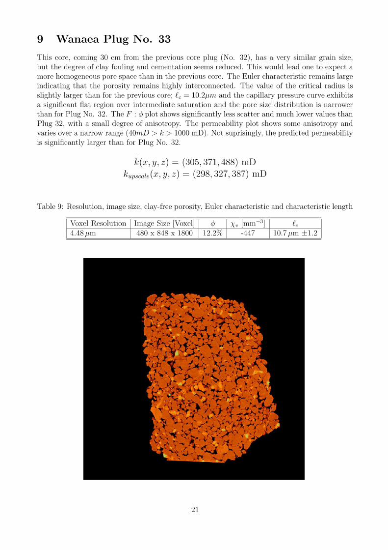
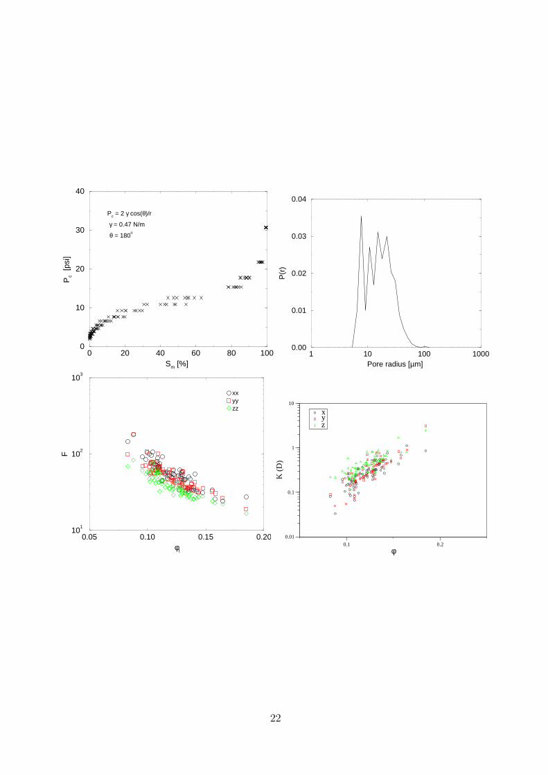
This core, coming 30 cm from the previous core plug (No. 32), has a very similar grain size,but the degree of clay fouling and cementation seems reduced. This would lead one to expect amore homogeneous pore space than in the previous core. The Euler characteristic remains largeindicating that the porosity remains highly interconnected. The value of the critical radius isslightly larger than for the previous core; `c = 10.2µm and the capillary pressure curve exhibitsa significant flat region over intermediate saturation and the pore size distribution is narrowerthan for Plug No. 32. The F : φ plot shows significantly less scatter and much lower values thanPlug 32, with a small degree of anisotropy. The permeability plot shows some anisotropy andvaries over a narrow range (40mD > k > 1000 mD). Not suprisingly, the predicted permeabilityis significantly larger than for Plug No. 32.
k̄(x, y, z) = (305, 371, 488) mDkupscale(x, y, z) = (298, 327, 387) mD
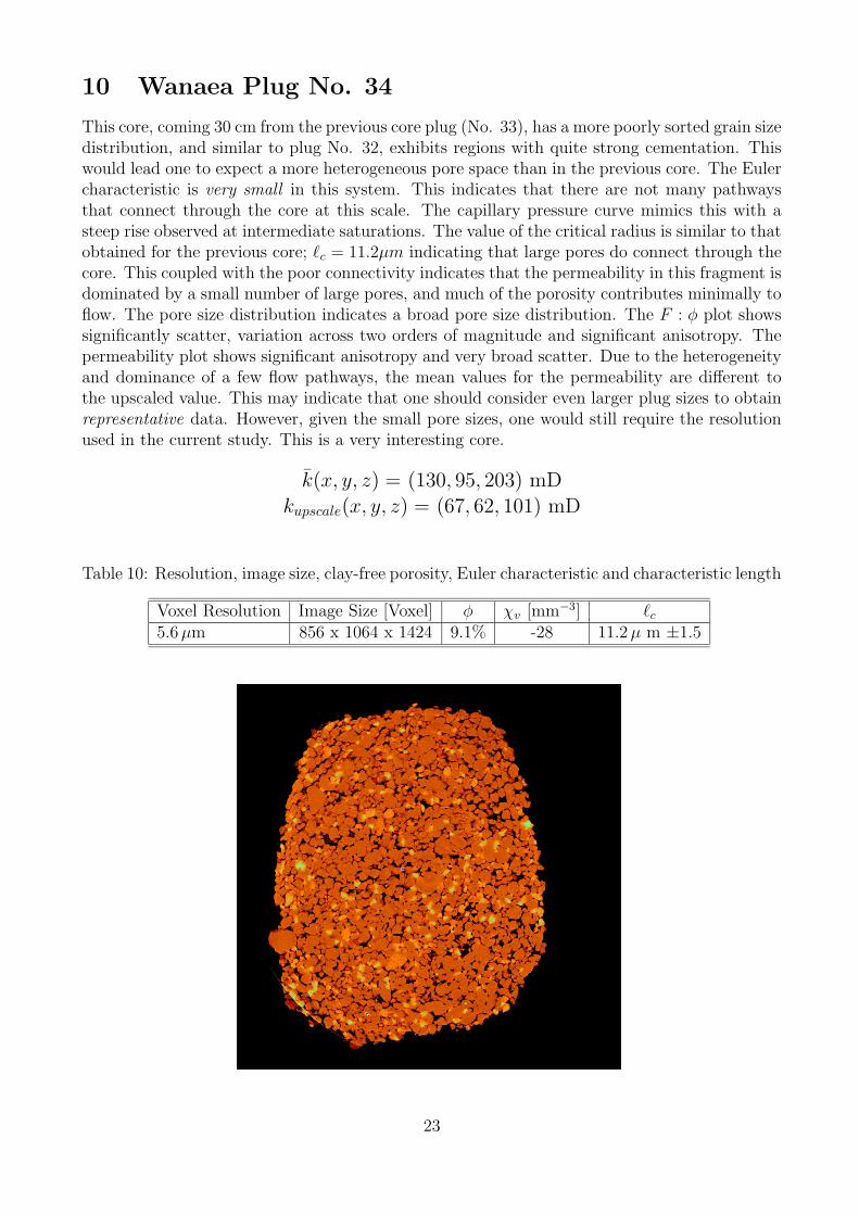
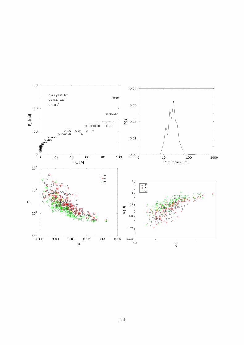
This core, coming 30 cm from the previous core plug (No. 33), has a more poorly sorted grain sizedistribution, and similar to plug No. 32, exhibits regions with quite strong cementation. Thiswould lead one to expect a more heterogeneous pore space than in the previous core. The Eulercharacteristic is very small in this system. This indicates that there are not many pathwaysthat connect through the core at this scale. The capillary pressure curve mimics this with asteep rise observed at intermediate saturations. The value of the critical radius is similar to thatobtained for the previous core; `c = 11.2µm indicating that large pores do connect through thecore. This coupled with the poor connectivity indicates that the permeability in this fragment isdominated by a small number of large pores, and much of the porosity contributes minimally toflow. The pore size distribution indicates a broad pore size distribution. The F : φ plot showssignificantly scatter, variation across two orders of magnitude and significant anisotropy. Thepermeability plot shows significant anisotropy and very broad scatter. Due to the heterogeneityand dominance of a few flow pathways, the mean values for the permeability are different tothe upscaled value. This may indicate that one should consider even larger plug sizes to obtainrepresentative data. However, given the small pore sizes, one would still require the resolutionused in the current study. This is a very interesting core.
k̄(x, y, z) = (130, 95, 203) mDkupscale(x, y, z) = (67, 62, 101) mD