Digital Design: An Embedded Systems Approach Using Verilog Chapter 3 Numeric Basics Portions of this work are from the book, Digital Design: An Embedded Systems Approach Using Verilog, by Peter J. Ashenden, published by Morgan Kaufmann Publishers, Copyright 2007 Elsevier Inc. All rights reserved.
Transcript
Digital Design:An Embedded Systems Approach Using Verilog
Chapter 3Numeric Basics
Portions of this work are from the book, Digital Design: An Embedded Systems Approach Using Verilog, by Peter J. Ashenden, published by Morgan Kaufmann Publishers, Copyright 2007 Elsevier Inc. All rights reserved.
Digital Design — Chapter 3 — Numeric Basics 2
Verilog
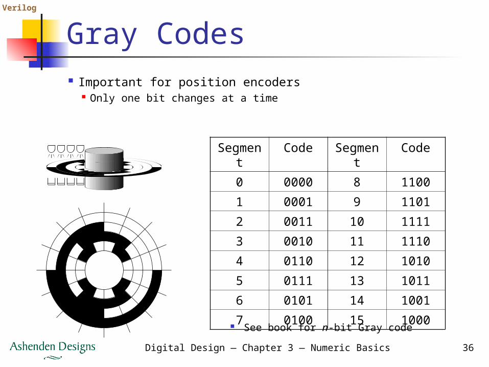
Numeric Basics
Representing and processing numeric data is a common requirement unsigned integers signed integers fixed-point real numbers floating-point real numbers complex numbers
Digital Design — Chapter 3 — Numeric Basics 3
Verilog
Unsigned Integers
Non-negative numbers (including 0) Represent real-world data
e.g., temperature, position, time, … Also used in controlling operation of a
digital system e.g., counting iterations, table indices
Coded using unsigned binary (base 2) representation analogous to decimal representation
Digital Design — Chapter 3 — Numeric Basics 4
Verilog
Binary Representation
Decimal: base 10 12410 = 1×10² + 2×101 + 4×100
Binary: base 2 12410
= 1×26+1×25+1×24+1×23+1×22+0×21+0×20
= 11111002
In general, a number x is represented using n bits as xn–1, xn–2, …, x0, where
00
22
11 222 xxxx n
nn
n
Digital Design — Chapter 3 — Numeric Basics 5
Verilog
Binary Representation Unsigned binary is a code for numbers
n bits: represent numbers from 0 to 2n – 1 0: 0000…00; 2n – 1: 1111…11
Can convert between signed and unsigned interpretations
wire [11:0] s1;wire signed [11:0] s2;...assign s2 = $signed(s1); // s1 is known to be // less than 2**11...assign s1= $unsigned(s2); // s2 is known to be nonnegative
Digital Design — Chapter 3 — Numeric Basics 41
Verilog Octal and Hex Signed Integers
Don’t think of signed octal or hex Just treat octal or hex as shorthand
for a vector of bits E.g., 84410 is 001101001100
In hex: 0011 0100 1100 ⇒ 34C E.g., –4210 is 1111010110
In octal: 1 111 010 110 ⇒ 1726 (10 bits)
Digital Design — Chapter 3 — Numeric Basics 42
Verilog
Resizing Signed Integers
To extend a non-negative number Add leading 0 bits e.g., 5310 = 00110101 =
000000110101 To truncate a non-negative number
Discard leftmost bits, provided discarded bits are all 0 sign bit of result is 0
E.g., 4110 is 00101001 Truncating to 6 bits: 101001 — error!
Digital Design — Chapter 3 — Numeric Basics 43
Verilog
Resizing Signed Integers
To extend a negative number Add leading 1 bits
See textbook for proof e.g., –7510 = 10110101 =
111110110101 To truncate a negative number
Discard leftmost bits, provided discarded bits are all 1 sign bit of result is 1
Digital Design — Chapter 3 — Numeric Basics 44
Verilog
Resizing Signed Integers
In general, for 2s-complement integers Extend by replicating sign bit
sign extension Truncate by discarding leading bits
Discarded bits must all be the same, and the same as the sign bit of the result
wire signed [ 7:0] x;wire signed [15:0] y;...assign y = {{8{x[7]}}, x};assign y = x;...assign x = y;
… ……
x0
x1
xn − 1
y0
y1
yn − 1
yn
ym − 2
y
Digital Design — Chapter 3 — Numeric Basics 45
Verilog
Signed Negation
Complement and add 1 Note that
xx
xxx
xxx
xxxx
nn
nn
nn
nn
nn
nnn
n
nn
nn
11
021
00
22
11
00
022
211
1
00
22
11
22
1)22(2
)222(
1222222
12)1(2)1(2)1(1
ii xx 1
E.g., 43 is 00101011so –43 is 11010100 + 1 = 11010101
Digital Design — Chapter 3 — Numeric Basics 46
Verilog
Signed Negation
What about negating –2n–1? 1000…00 ⇒ 0111…11 + 1 = 1000…00 Result is –2n–1!
Recall range of n-bit numbers is not symmetric Either check for overflow, extend by
one bit, or ensure this case can’t arise In Verilog: use – operator
E.g., assign y = –x;
Digital Design — Chapter 3 — Numeric Basics 47
Verilog
Signed Addition
Perform addition as for unsigned Overflow if cn–1 differs from cn
See textbook for case analysis Can use the same circuit for signed
and unsigned addition
021
12
nn
n xxx 021
12
nn
n yyy
02021
11 2)(
nnn
nn yxyxyx
yields cn–1
Digital Design — Chapter 3 — Numeric Basics 48
Verilog
Signed Addition Examples
no overflow
positive overflow negative overflow
no overflow no overflow
no overflow
0 1 0 0 1 0 0 0
0 1 1 1 1 0 0 1
072:49:
121:
0 1 1 0 0 0 1
0 0 0 0 0 0 0 0
0 1 0 0 1 0 0 0
1 0 1 1 0 0 0 1
072:
105: 1 1 0 1 0 0 1
0 1 0 0 1 0 0 0
1 1 0 0 0 0 0 1
1 0 1 0 0 0 0 1
1–63:–32:
–95:
1 1 0 0 0 0 0
1 1 0 0 0 0 0 0
1 1 0 0 0 0 0 1
0 1 1 0 0 0 0 1
1–63:–96: 0 1 0 0 0 0 0
1 0 0 0 0 0 0 0
1 1 0 1 0 1 1 0
1 1 0 1 1 1 1 0
0–42:
–34:
8: 0 0 0 1 0 0 0
0 0 0 0 0 0 0 0
0 0 1 0 1 0 1 0
0 0 1 0 0 0 1 0
142:
34:
–8: 1 1 1 1 0 0 0
1 1 1 1 1 0 0 0
Digital Design — Chapter 3 — Numeric Basics 49
Verilog
Signed Addition in Verilog Result of + is same size as operands
wire signed [11:0] v1, v2;wire signed [12:0] sum;...assign sum = {v1[11], v1} + {v2[11], v2};...assign sum = v1 + v2; // implicit sign extension
To check overflow, compare signswire signed [7:0] x, y, z;wire ovf;...assign z = x + y;assign ovf = ~x[7] & ~y[7] & z[7] | x[7] & y[7] & ~z[7];
Digital Design — Chapter 3 — Numeric Basics 50
Verilog
Signed Subtraction
Use a 2s-complement adder Complement y and set c0 = 1
1)( yxyxyx
y0
y1
yn–1
y0
c0
cn
y1
yn–1
…
…
…
…
x0
x1
xn–1
x0
x1
xn–1
… s0
s1
sn–1
sn–1
/dn–1
s1/d
1s
0/d
0
…
cn–1
Digital Design — Chapter 3 — Numeric Basics 51
Verilog
Other Signed Operations
Increment, decrement same as unsigned
Comparison =, same as unsigned >, compare sign bits using
Multiplication Complicated by the need to sign
extend partial products Refer to Further Reading
11 nn yx
Digital Design — Chapter 3 — Numeric Basics 52
Verilog
Scaling Signed Integers
Multiplying by 2k
logical left shift (as for unsigned) truncate result using 2s-complement
rules Dividing by 2k
arithmetic right shift discard k bits from the right, and
replicate sign bit k times on the left e.g., s = "11110011" -- –13
shift_right(s, 2) = "11111100" -- –13 / 22
Digital Design — Chapter 3 — Numeric Basics 53
Verilog
Fixed-Point Numbers
Many applications use non-integers especially signal-processing apps
Fixed-point numbers allow for fractional parts represented as integers that are
implicitly scaled by a power of 2 can be unsigned or signed
Digital Design — Chapter 3 — Numeric Basics 54
Verilog
Positional Notation
In decimal2101
10 10410210010124.10
In binary
1021012
2 25.5212021202101.101
Represent as a bit vector: 10101 binary point is implicit
Digital Design — Chapter 3 — Numeric Basics 55
Verilog
Unsigned Fixed-Point
n-bit unsigned fixed-point m bits before and f bits after binary point
ff
mm xxxxx
2222 11
00
11
Range: 0 to 2m – 2–f
Precision: 2–f
m may be ≤ 0, giving fractions only e.g., m= –2: 0.0001001101
Digital Design — Chapter 3 — Numeric Basics 56
Verilog
Signed Fixed-Point
n-bit signed 2s-complement fixed-point m bits before and f bits after binary point
ff
mm xxxxx
2222 11
00
11
Range: –2m–1 to 2m–1 – 2–f
Precision: 2–f
E.g., 111101, signed fixed-point, m = 2 11.11012 = –2 + 1 + 0.5 + 0.25 + 0.0625
= –0.187510
Digital Design — Chapter 3 — Numeric Basics 57
Verilog Choosing Range and Precision
Choice depends on application Need to understand the numerical
behavior of computations performed some operations can magnify
quantization errors In DSP
fixed-point range affects dynamic range precision affects signal-to-noise ratio
Perform simulations to evaluate effects
Digital Design — Chapter 3 — Numeric Basics 58
Verilog
Fixed-Point in Verilog
Use vectors with implied scaling Index range matches powers of
weights Assume binary point between indices
0 and –1module fixed_converter ( input [5:-7] in, output signed [7:-7] out ); assign out = {2'b0, in};endmodule
Digital Design — Chapter 3 — Numeric Basics 59
Verilog
Fixed-Point Operations
Just use integer hardware e.g., addition:
fff yxyx 2/)22(
Ensure binary points are aligned
x0
10-bitadder
……a
–4
a–5
a–6
a–7
x7
a3
x8
x9
y0……
b–4
y7
b3
b4
b5
c–4
c3
c4
c5
…
y8
y9
s0…
Digital Design — Chapter 3 — Numeric Basics 60
Verilog
Floating-Point Numbers
Similar to scientific notation for decimal e.g., 6.02214199×10²³, 1.60217653×10⁻¹⁹
Allow for larger range, with same relative precision throughout the range