98
Digital Design with Synthesizable VHDL Prof. Stephen A. Edwards [email protected] Columbia University Spring 2011 Digital Design with Synthesizable VHDL – p.

Digital Design withSynthesizable VHDL
Prof. Stephen A. Edwards
Columbia University
Spring 2011
Digital Design with Synthesizable VHDL – p. 1

Why HDLs?
Y
B
A
Vdd
Vss
B
A
Y
1970s: SPICE transistor-level netlists
An XOR built from four NAND gates
.MODEL P PMOS
.MODEL N NMOS
.SUBCKT NAND A B Y Vdd Vss
M1 Y A Vdd Vdd P
M2 Y B Vdd Vdd P
M3 Y A X Vss N
M4 X B Vss Vss N
.ENDS
X1 A B I1 Vdd 0 NAND
X2 A I1 I2 Vdd 0 NAND
X3 B I1 I3 Vdd 0 NAND
X4 I2 I3 Y Vdd 0 NAND
Digital Design with Synthesizable VHDL – p. 2

Why HDLs?
1980s: Graphical schematic capture programs
Digital Design with Synthesizable VHDL – p. 3

Why HDLs?
1990s: HDLs and Logic Synthesis
library ieee;
use ieee.std_logic_1164.all;
use ieee.numeric_std.all;
entity ALU is
port( A: in unsigned(1 downto 0);
B: in unsigned(1 downto 0);
Sel: in unsigned(1 downto 0);
Res: out unsigned(1 downto 0));
end ALU;
architecture behv of ALU is begin
process (A,B,Sel) begin
case Sel is
when "00" => Res <= A + B;
when "01" => Res <= A + (not B) + 1;
when "10" => Res <= A and B;
when "11" => Res <= A or B;
when others => Res <= "XX";
end case;
end process;
end behv;
Digital Design with Synthesizable VHDL – p. 4
Two Separate but Equal Languages
Verilog and VHDLVerilog: More succinct, less flexible, really messyVHDL: Verbose, very (too?) flexible, fairly messyPart of languages people actually use identical.Every synthesis system supports both.
Digital Design with Synthesizable VHDL – p. 5

Basic Lexical Rules of VHDL
Free-form: space only separates tokens.
Case-insensitive: “VHDL,” “vHdL,” and “vhdl”are equivalent.
Comments: from “” to the end of the line.
Identifiers: [azAZ](_?[azAZ09])*
Examples: X X_or_Y ADDR addr
Illegal: 14M CLK__4 FOO_
Digital Design with Synthesizable VHDL – p. 6

Literals in VHDL
Decimal integers∗: 1 42 153_1203
Based integers∗: 2#1_0010# 16#F001D#
Characters: ’0’ ’1’ ’X’
Strings: "101011" "XXXXXX"
Bit string literals∗: B"1001_0101" X"95"
mean "10010101"
∗Underscores added for readability are ignored
Digital Design with Synthesizable VHDL – p. 7
Combinational Logic in a
Dataflow Style
Digital Design with Synthesizable VHDL – p. 8

Bits
Logical True False
Binary 1 0
Voltage 1.65–3.3V 0–1.65V
Timing Diagram HHH LLL
VHDL ’1’ ’0’
In VHDL, zeros and ones on wires are membersof an enumerated type. They are not Boolean.
Digital Design with Synthesizable VHDL – p. 9
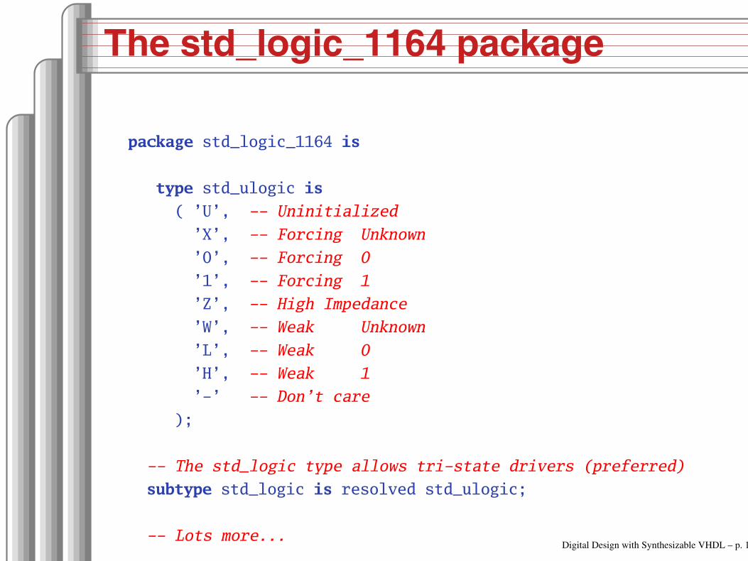
The std_logic_1164 package
package std_logic_1164 is
type std_ulogic is
( ’U’, Uninitialized
’X’, Forcing Unknown
’0’, Forcing 0
’1’, Forcing 1
’Z’, High Impedance
’W’, Weak Unknown
’L’, Weak 0
’H’, Weak 1
’’ Don’t care
);
The std_logic type allows tristate drivers (preferred)
subtype std_logic is resolved std_ulogic;
Lots more...Digital Design with Synthesizable VHDL – p. 10

Boolean Operators
The basic ones in VHDL:
a b a and b a or b not a
’0’ ’0’ ’0’ ’0’ ’1’
’0’ ’1’ ’0’ ’1’ ’1’
’1’ ’0’ ’0’ ’1’ ’0’
’1’ ’1’ ’1’ ’1’ ’0’
a b a nand b a nor b a xor b
’0’ ’0’ ’1’ ’1’ ’0’
’0’ ’1’ ’1’ ’0’ ’1’
’1’ ’0’ ’1’ ’0’ ’1’
’1’ ’1’ ’0’ ’0’ ’0’Digital Design with Synthesizable VHDL – p. 11

Rules of Boolean Algebra (1)
Precedence
not a or b and c = (not a) or (b and c)
Basic relationships
not not a = a
a and ’1’ = a
a and ’0’ = ’0’
a or ’1’ = ’1’
a or ’0’ = a
a and a = a
a and not a = ’0’
a or a = a
a or not a = ’1’
a nand b = not (a and b)
a nor b = not (a or b)
a xor ’0’ = a
a xor ’1’ = not a
a xor b = (not a and b) or (a and not b)Digital Design with Synthesizable VHDL – p. 12

Rules of Boolean Algebra (2)
Commutativity
a and b = b and a
a or b = b or a
Associativity
a and (b and c) = (a and b) and c
a or (b or c) = (a or b) or c
Distributivity
a and (b or c) = a and b or a and c
a or (b and c) = (a or b) and (a or c)
De Morgan’s Law
not (a and b) = not a or not b
not (a or b) = not a and not b
Digital Design with Synthesizable VHDL – p. 13

A Full Adder: Truth Table
a b c carry sum
0 0 0 0 0
0 0 1 0 1
0 1 0 0 1
0 1 1 1 0
1 0 0 0 1
1 0 1 1 0
1 1 0 1 0
1 1 1 1 1
carry <=
(not a and b and c) or
( a and not b and c) or
( a and b and not c) or
( a and b and c);
sum <=
(not a and not b and c) or
(not a and b and not c) or
( a and not b and not c) or
( a and b and c);
Each row represents a minterm
Sum-of-products form: sum of each minterm inwhich output is true
Digital Design with Synthesizable VHDL – p. 14

Simplifying Using Boolean Rules
carry <= (not a and b and c) or (a and not b and c) or
(a and b and not c) or (a and b and c);
<= (a and b and not c) or (a and b and c) or
(not a and b and c) or (a and b and c) or
(a and not b and c) or (a and b and c);
<= (a and b) or (b and c) or (a and c);
sum <= (not a and not b and c) or (not a and b and not c) or
(a and not b and not c) or (a and b and c);
<= (not a) and ((not b and c) or (b and not c)) or
a and ((not b and not c) or (b and c));
<= a xor b xor c;
Digital Design with Synthesizable VHDL – p. 15

Structure of a VHDL Module
Ports
in
in
out
out
inout
Component
Component
X <= ’1’ when Y = ’1’ and X = "110" else ’0’
Dataflow Expression
Process
process (clk)
begin
if rising_edge(clk) then
count <= count + 1;
end if;
end process;
Signal
Digital Design with Synthesizable VHDL – p. 16

A Full Adder in VHDL
a
b
c
sumcarry
library ieee; always needed
use ieee.std_logic_1164.all; std_logic, et al.
entity full_adder is the interface
port(a, b, c : in std_logic;
sum, carry : out std_logic);
end full_adder;
architecture imp of full_adder is the implementation
begin
sum <= (a xor b) xor c; combinational logic
carry <= (a and b) or (a and c) or (b and c);
end imp;
Digital Design with Synthesizable VHDL – p. 17
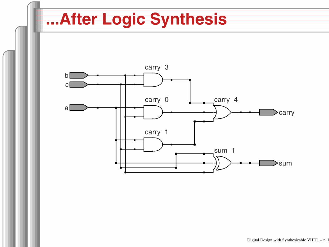
...After Logic Synthesis
sum~ 1
carry~ 0
carry~ 1
carry~ 4a
b
c
sum
carry
carry~ 3
Digital Design with Synthesizable VHDL – p. 18

Vectors of Bits
Three standard synthesizable bit vector types:
Type Library Logic Arith. Neg.
std_logic_vector ieee_std_1164√
unsigned numeric_std√ √
signed numeric_std√ √ √
library ieee;
use ieee.std_logic_1164.all;
use ieee.numeric_std.all;
entity vectors is
port(vect : in std_logic_vector(1 downto 0);
unsi : in unsigned(7 downto 0);
sign : out unsigned(15 downto 0));
end entity; Digital Design with Synthesizable VHDL – p. 19

Endianness
The perpetual battle: Is “0” most or leastsignificant?
Little Endian 3 2 1 0 unsigned(3 downto 0)
Big Endian 0 1 2 3 unsigned(0 to 3)
Arguments on both sides will continue forever.
I suggest using Little Endian for vectors.
Digital Design with Synthesizable VHDL – p. 20

Binary and Hexadecimal in VHDL
Decimal Binary Hex
0 "0" x"0"
1 "1" x"1"
2 "10" x"2"
3 "11" x"3"
4 "100" x"4"
5 "101" x"5"
6 "110" x"6"
7 "111" x"7"
8 "1000" x"8"
9 "1001" x"9"
10 "1010" x"A"
11 "1011" x"B"
12 "1100" x"C"
13 "1101" x"D"
14 "1110" x"E"
15 "1111" x"F"
16 "10000" x"10"
17 "10001" x"11"
18 "10010" x"12"
19 "10011" x"13"
Vector types are arrays ofstd_logic
Literals are therefore stringsof 0’s and 1’s from std_logic_1164
type std_logic_vector is
array (natural range <>) of std_logic;
from numeric_std
type unsigned is
array (natural range <>) of std_logic;
type signed is
array (natural range <>) of std_logic;
Digital Design with Synthesizable VHDL – p. 21

Two’s Complement
Decimal Binary Hex
8 "1000" x"8"
7 "1001" x"9"
6 "1010" x"A"
5 "1011" x"B"
4 "1100" x"C"
3 "1101" x"D"
2 "1110" x"E"
1 "1111" x"F"
0 "0000" x"0"
1 "0001" x"1"
2 "0010" x"2"
3 "0011" x"3"
4 "0100" x"4"
5 "0101" x"5"
6 "0110" x"6"
7 "0111" x"7"
How do you represent negativenumbers?
Two’s complement producessimpler logic than sign bit alone.
Idea: Add constant 2n tonegative numbers. Simplydiscard overflow after additionor subtraction.
An n-bit number represents
−2n−1 to 2n−1 −1.
The signed type innumeric_std uses this
Digital Design with Synthesizable VHDL – p. 22

A Hex-to-seven-segment Decoder
a
b
c
d
e
f
g
Digital Design with Synthesizable VHDL – p. 23

VHDL: Hex-to-7-segment Decoder
library ieee;
use ieee.std_logic_1164.all;
use ieee.numeric_std.all; Provides the unsigned type
entity hex7seg is
port ( input : in unsigned(3 downto 0); A number
output : out std_logic_vector(6 downto 0)); Just bits
end hex7seg;
architecture combinational of hex7seg is
begin
with input select output <=
"0111111" when x"0", "0000110" when x"1", Bad style
"1011011" when x"2", "1001111" when x"3", one case
"1100110" when x"4", "1101101" when x"5", per line
"1111101" when x"6", "0000111" when x"7", preferred
"1111111" when x"8", "1101111" when x"9",
"1110111" when x"A", "1111100" when x"B",
"0111001" when x"C", "1011110" when x"D",
"1111001" when x"E", "1110001" when x"F",
"XXXXXXX" when others;
end combinational; Digital Design with Synthesizable VHDL – p. 24

Four-to-one mux: when .. else
library ieee;
use ieee.std_logic_1164.all;
use ieee.numeric_std.all;
entity multiplexer_4_1 is
port(in0, in1, in2, in3 : in unsigned(15 downto 0);
s : in unsigned(1 downto 0);
z : out unsigned(15 downto 0));
end multiplexer_4_1;
architecture comb of multiplexer_4_1 is
begin
z <= in0 when s = "00" else
in1 when s = "01" else
in2 when s = "10" else
in3 when s = "11" else
(others => ’X’); Shorthand for "all X’s"
end comb;
Digital Design with Synthesizable VHDL – p. 25

Four-to-one mux: with...select
library ieee;
use ieee.std_logic_1164.all;
use ieee.numeric_std.all;
entity multiplexer_4_1 is
port(in0, in1, in2, in3 : in unsigned(15 downto 0);
s0, s1 : in std_logic;
z : out unsigned(15 downto 0));
end multiplexer_4_1;
architecture comb of multiplexer_4_1 is
signal sels : unsigned(1 downto 0);
begin
sels <= s1 & s0; "&" is vector concatenation
with sels select would not resolve type if "s1 & s0" here
z <= in0 when "00",
in1 when "01",
in2 when "10",
in3 when "11",
(others => ’X’) when others;
end comb;
Digital Design with Synthesizable VHDL – p. 26

Three-to-eight Decoder
library ieee;
use ieee.std_logic_1164.all;
use ieee.numeric_std.all;
entity dec1_8 is
port (
sel : in unsigned(2 downto 0);
res : out unsigned(7 downto 0));
end dec1_8;
architecture comb of dec1_8 is
begin
res <= "00000001" when sel = "000" else
"00000010" when sel = "001" else
"00000100" when sel = "010" else
"00001000" when sel = "011" else
"00010000" when sel = "100" else
"00100000" when sel = "101" else
"01000000" when sel = "110" else
"10000000";
end comb; Digital Design with Synthesizable VHDL – p. 27
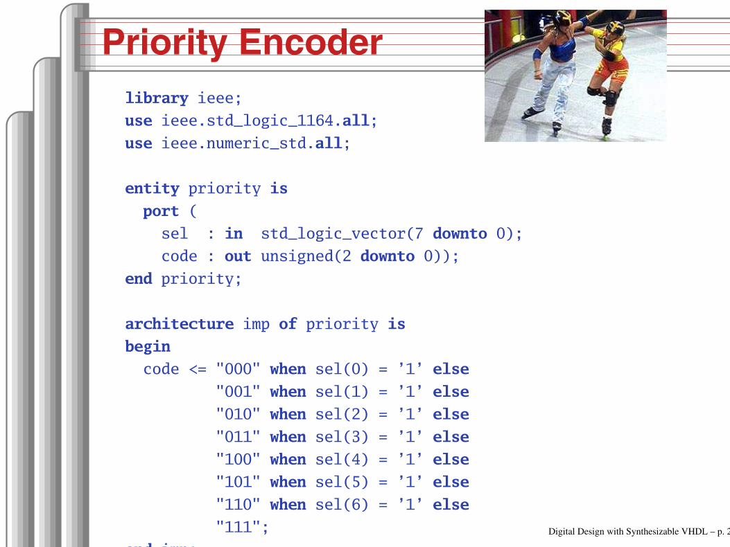
Priority Encoder
library ieee;
use ieee.std_logic_1164.all;
use ieee.numeric_std.all;
entity priority is
port (
sel : in std_logic_vector(7 downto 0);
code : out unsigned(2 downto 0));
end priority;
architecture imp of priority is
begin
code <= "000" when sel(0) = ’1’ else
"001" when sel(1) = ’1’ else
"010" when sel(2) = ’1’ else
"011" when sel(3) = ’1’ else
"100" when sel(4) = ’1’ else
"101" when sel(5) = ’1’ else
"110" when sel(6) = ’1’ else
"111";
end imp;
Digital Design with Synthesizable VHDL – p. 28

Integer Arithmetic
library ieee;
use ieee.std_logic_1164.all;
use ieee.numeric_std.all;
entity adder is
port (
A, B : in unsigned(7 downto 0);
CI : in std_logic;
SUM : out unsigned(7 downto 0);
CO : out std_logic);
end adder;
architecture imp of adder is
signal tmp : unsigned(8 downto 0);
begin
tmp <= A + B + ("0" & ci); trick to promote ci to unsigned
SUM <= tmp(7 downto 0);
CO <= tmp(8);
end imp;Digital Design with Synthesizable VHDL – p. 29
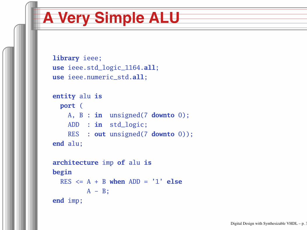
A Very Simple ALU
library ieee;
use ieee.std_logic_1164.all;
use ieee.numeric_std.all;
entity alu is
port (
A, B : in unsigned(7 downto 0);
ADD : in std_logic;
RES : out unsigned(7 downto 0));
end alu;
architecture imp of alu is
begin
RES <= A + B when ADD = ’1’ else
A B;
end imp;
Digital Design with Synthesizable VHDL – p. 30
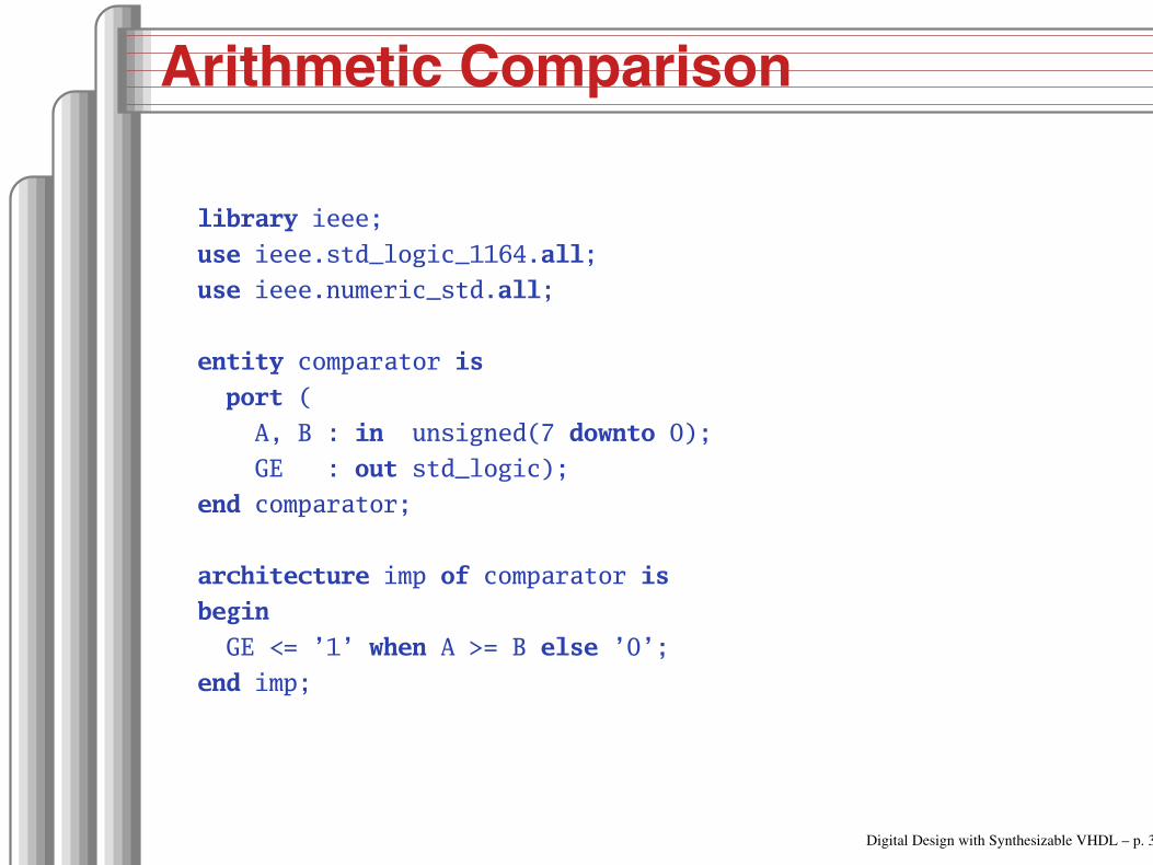
Arithmetic Comparison
library ieee;
use ieee.std_logic_1164.all;
use ieee.numeric_std.all;
entity comparator is
port (
A, B : in unsigned(7 downto 0);
GE : out std_logic);
end comparator;
architecture imp of comparator is
begin
GE <= ’1’ when A >= B else ’0’;
end imp;
Digital Design with Synthesizable VHDL – p. 31
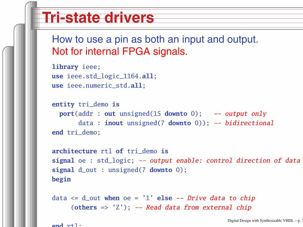
Tri-state drivers
How to use a pin as both an input and output.Not for internal FPGA signals.
library ieee;
use ieee.std_logic_1164.all;
use ieee.numeric_std.all;
entity tri_demo is
port(addr : out unsigned(15 downto 0); output only
data : inout unsigned(7 downto 0)); bidirectional
end tri_demo;
architecture rtl of tri_demo is
signal oe : std_logic; output enable: control direction of data
signal d_out : unsigned(7 downto 0);
begin
data <= d_out when oe = ’1’ else Drive data to chip
(others => ’Z’); Read data from external chip
end rtl;Digital Design with Synthesizable VHDL – p. 32
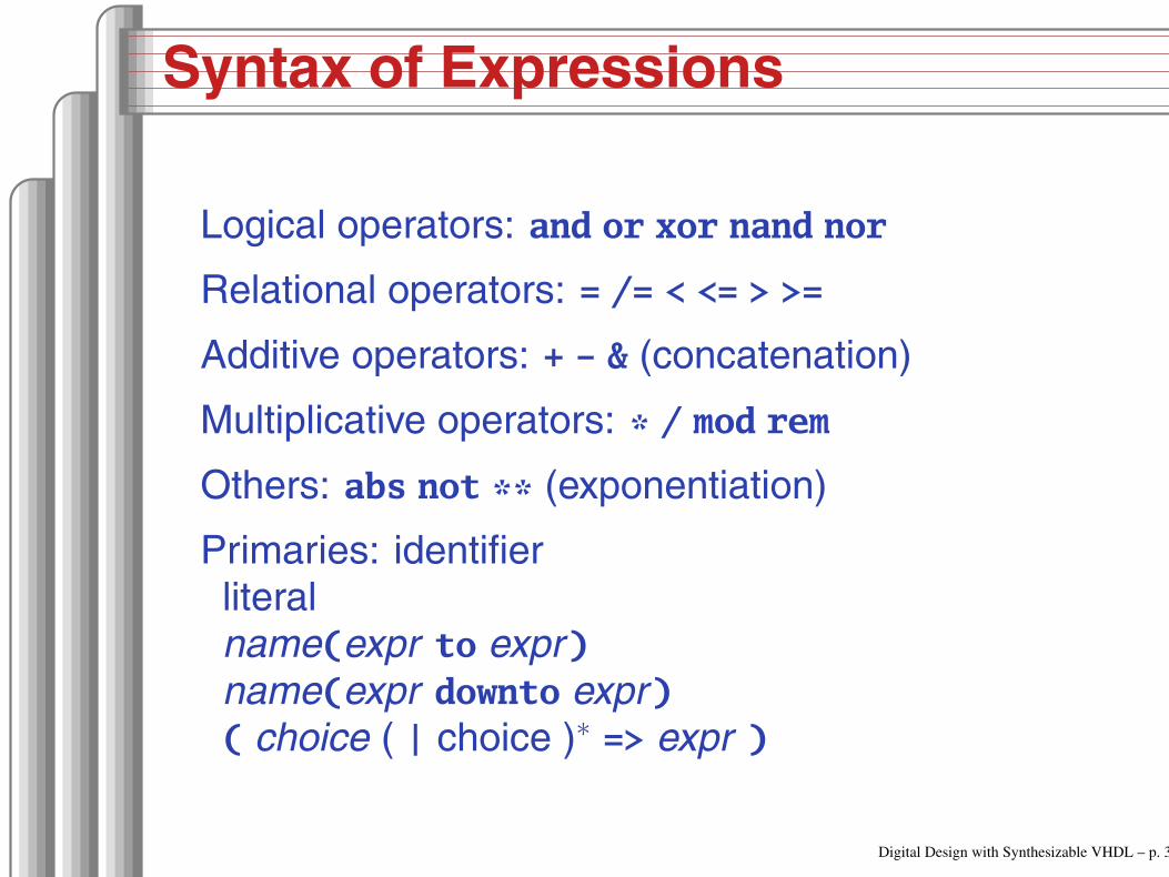
Syntax of Expressions
Logical operators: and or xor nand nor
Relational operators: = /= < <= > >=
Additive operators: + & (concatenation)
Multiplicative operators: * / mod rem
Others: abs not ** (exponentiation)
Primaries: identifierliteralname(expr to expr)name(expr downto expr)( choice ( | choice )∗ => expr )
Digital Design with Synthesizable VHDL – p. 33

Summary of Dataflow Modeling
Conditional signal assignment (when...else)
target <=(expr when expr else)∗
expr ;
Selected signal assignment (with...select)
with expr selecttarget <=(expr when choice (| choice)∗,)∗
expr when choice (| choice)∗ ;
A choice is a simple expression (i.e., notlogical or comparison) or others.
Note: when does not nest (i.e., it’s not an expr ).Digital Design with Synthesizable VHDL – p. 34

Hierarchy: Instantiating
components (entities)
Digital Design with Synthesizable VHDL – p. 35

Hierarchy: port map positional style
aA(0)
bB(0)
c’0’
sumC(0)
carry
aA(1)
bB(1)
csum
C(1)
carryC(2)
carry
library ieee;
use ieee.std_logic_1164.all;
use ieee.numeric_std.all;
entity add2 is
port (A, B : in unsigned(1 downto 0);
C : out unsigned(2 downto 0));
end add2;
architecture imp of add2 is
component full_adder
port (a, b, c : in std_logic;
sum, carry : out std_logic);
end component;
signal carry : std_logic;
begin
bit0 : full_adder port map ( A(0), B(0), ’0’, C(0), carry );
bit1 : full_adder port map ( A(1), B(1), carry, C(1), C(2) );
end imp;Digital Design with Synthesizable VHDL – p. 36

Hierarchy: port map by-name style
library ieee;
use ieee.std_logic_1164.all;
use ieee.numeric_std.all;
entity add2n is
port (A, B : in unsigned(1 downto 0);
C : out unsigned(2 downto 0));
end add2n;
architecture imp of add2n is
component full_adder
port (a, b, c : in std_logic;
sum, carry : out std_logic);
end component;
signal carry : std_logic;
begin
bit0 : full_adder port map (a => A(0), b => B(0), c => ’0’,
sum => C(0), carry => carry);
bit1 : full_adder port map (a => A(1), b => B(1), c => carry,
sum => C(1), carry => C(2));
end imp; Digital Design with Synthesizable VHDL – p. 37

Direct Instantiation (no component)
library ieee;
use ieee.std_logic_1164.all;
use ieee.numeric_std.all;
entity add2 is
port (A, B : in unsigned(1 downto 0);
C : out unsigned(2 downto 0));
end add2;
architecture imp of add2 is
signal carry : std_logic;
begin
bit0 : entity work.full_adder everything in "work" project
port map ( A(0), B(0), ’0’, C(0), carry );
bit1 : entity work.full_adder
port map ( A(1), B(1), carry, C(1), C(2) );
end imp;
Must be compiled after full_adder.vhd! Digital Design with Synthesizable VHDL – p. 38

Generate: Ripple-carry adder
library ieee;
use ieee.std_logic_1164.all;
use ieee.numeric_std.all;
entity rippleadder is
port (a, b : in unsigned(3 downto 0);
cin : in std_logic;
sum : out unsigned(3 downto 0);
cout : out std_logic);
end rippleadder;
architecture imp of rippleadder is
signal c : unsigned(4 downto 0);
begin
c(0) <= cin;
G1: for m in 0 to 3 generate expanded at compile time
sum(m) <= a(m) xor b(m) xor c(m);
c(m+1) <= (a(m) and b(m)) or (b(m) and c(m)) or
(a(m) and c(m));
end generate G1;
cout <= c(4);
end imp;Digital Design with Synthesizable VHDL – p. 39

Combinational Logic in a
Procedural Style
Digital Design with Synthesizable VHDL – p. 40

Processes
Process: sequential code fragment invoked whensignal in sensitivity list changes.A correct, but dumb way to model an inverter:
library ieee;
use ieee.std_logic_1164.all;
entity dumb_inv is
port( a: in std_logic; y : out std_logic );
end dumb_inv;
architecture comb of dumb_inv is
begin
process (a) invoked when signal a changes
begin
if a = ’1’ then y <= ’0’; else y <= ’1’; end if;
end process;
end comb;Digital Design with Synthesizable VHDL – p. 41

A 4-to-1 mux in the procedural style
library ieee;
use ieee.std_logic_1164.all;
use ieee.numeric_std.all;
entity pmultiplexer_4_1 is
port(in0, in1, in2, in3 : in unsigned(15 downto 0);
s : in unsigned(1 downto 0);
z : out unsigned(15 downto 0));
end pmultiplexer_4_1;
architecture comb of pmultiplexer_4_1 is
begin
process (in0, in1, in2, in3, s)
begin
z <= (others => ’X’); default
if s = "00" then z <= in0; assignment overrides default
elsif s = "01" then z <= in1;
elsif s = "10" then z <= in2;
elsif s = "11" then z <= in3;
end if;
end process;
end comb;
Digital Design with Synthesizable VHDL – p. 42
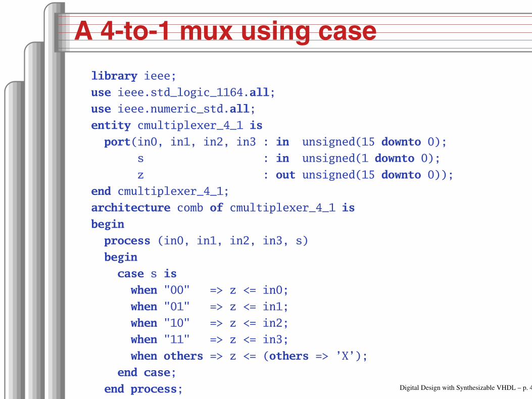
A 4-to-1 mux using case
library ieee;
use ieee.std_logic_1164.all;
use ieee.numeric_std.all;
entity cmultiplexer_4_1 is
port(in0, in1, in2, in3 : in unsigned(15 downto 0);
s : in unsigned(1 downto 0);
z : out unsigned(15 downto 0));
end cmultiplexer_4_1;
architecture comb of cmultiplexer_4_1 is
begin
process (in0, in1, in2, in3, s)
begin
case s is
when "00" => z <= in0;
when "01" => z <= in1;
when "10" => z <= in2;
when "11" => z <= in3;
when others => z <= (others => ’X’);
end case;
end process;
end comb;
Digital Design with Synthesizable VHDL – p. 43

An Address Decoder
library ieee;
use ieee.std_logic_1164.all;
use ieee.numeric_std.all;
entity adecoder is
port(a : in unsigned(15 downto 0);
ram, rom, video, io : out std_logic);
end adecoder;
architecture proc of adecoder is
begin
process (a)
begin
ram <= ’0’; rom <= ’0’; video <= ’0’; io <= ’0’;
if a(15) = ’0’ then ram <= ’1’; 00007FFF
elsif a(14 downto 13) = "00" then video <= ’1’; 80009FFF
elsif a(14 downto 12) = "101" then io <= ’1’; D000DFFF
elsif a(14 downto 13) = "11" then rom <= ’1’; E000FFFF
end if;
end process;
end proc; Digital Design with Synthesizable VHDL – p. 44

Summary of Procedural Modeling
null
signal <= expr ;
variable := expr ;
if expr then stmts(elsif expr then stmts)∗
(else stmts)?end if;
case expr is(when choices => stmts)∗
end case;
Note: when...else and with...select not allowed
Digital Design with Synthesizable VHDL – p. 45

Sequential Logic
Digital Design with Synthesizable VHDL – p. 46

Basic D Flip-Flop
D
Clk
Q
library ieee;
use ieee.std_logic_1164.all;
entity flipflop is
port (Clk, D : in std_logic;
Q : out std_logic);
end flipflop;
architecture imp of flipflop is
begin
process (Clk) Sensitive only to Clk
begin
if rising_edge(Clk) then Only on the rising edge of Clk
Q <= D;
end if;
end process;
end imp;Digital Design with Synthesizable VHDL – p. 47

Flip-Flop with Latch Enable
1
0D
Clk
Q
EN
library ieee;
use ieee.std_logic_1164.all;
entity flipflop_enable is
port (Clk, Reset, D, EN : in std_logic;
Q : out std_logic);
end flipflop_enable;
architecture imp of flipflop_enable is
begin
process (Clk)
begin
if rising_edge(Clk) then
if EN = ’1’ then
Q <= D;
end if;
end if;
end process;
end imp;
Digital Design with Synthesizable VHDL – p. 48

Flip-Flop with Synchronous Reset
library ieee;
use ieee.std_logic_1164.all;
entity flipflop_reset is
port (Clk, Reset, D : in std_logic;
Q : out std_logic);
end flipflop_reset;
architecture imp of flipflop_reset is
begin
process (Clk)
begin
if rising_edge(Clk) then
if Reset = ’1’ then
Q <= ’0’;
else
Q <= D;
end if;
end if;
end process;
end imp; Digital Design with Synthesizable VHDL – p. 49
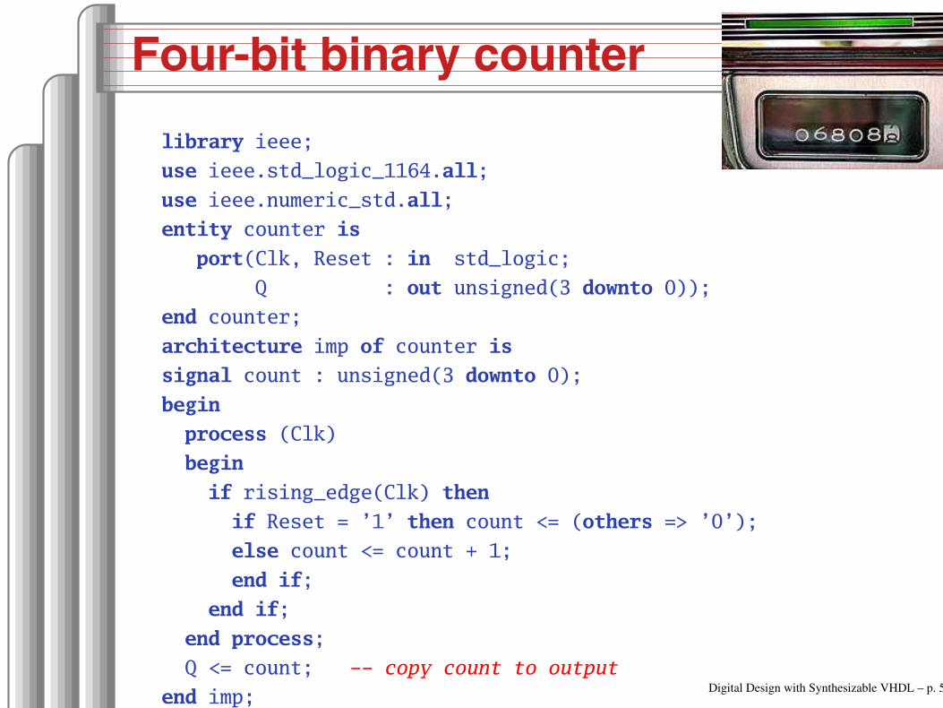
Four-bit binary counter
library ieee;
use ieee.std_logic_1164.all;
use ieee.numeric_std.all;
entity counter is
port(Clk, Reset : in std_logic;
Q : out unsigned(3 downto 0));
end counter;
architecture imp of counter is
signal count : unsigned(3 downto 0);
begin
process (Clk)
begin
if rising_edge(Clk) then
if Reset = ’1’ then count <= (others => ’0’);
else count <= count + 1;
end if;
end if;
end process;
Q <= count; copy count to output
end imp;Digital Design with Synthesizable VHDL – p. 50

Eight-bit serial in/out shift register
library ieee;
use ieee.std_logic_1164.all;
entity shifter is
port ( Clk, SI : in std_logic;
SO : out std_logic);
end shifter;
architecture impl of shifter is
signal tmp : std_logic_vector(7 downto 0);
begin
process (Clk)
begin
if rising_edge(Clk) then
tmp <= tmp(6 downto 0) & SI; & is concatenation
end if;
end process;
SO <= tmp(7); Copy to output
end impl; Digital Design with Synthesizable VHDL – p. 51

Synchronous RAM
library ieee;
use ieee.std_logic_1164.all;
use ieee.numeric_std.all;
entity ram_32_4 is
port (
Clk, WE : in std_logic; Clock and write enable
addr : in unsigned(4 downto 0);
di : in unsigned(3 downto 0); Data in
do : out unsigned(3 downto 0)); Data out
end ram_32_4;
architecture imp of ram_32_4 is
type ram_type is array(0 to 31) of unsigned(3 downto 0);
signal RAM : ram_type;
begin
process (Clk) begin
if rising_edge(Clk) then
if we = ’1’ then RAM(TO_INTEGER(addr)) <= di;
do <= di; writethrough
else do <= RAM(TO_INTEGER(addr));
end if; end if;
end process;
end imp;
Digital Design with Synthesizable VHDL – p. 52

A small ROM
library ieee;
use ieee.std_logic_1164.all;
use ieee.numeric_std.all;
entity rom_32_4 is
port (Clk, en : in std_logic;
addr : in unsigned(3 downto 0);
data : out unsigned(3 downto 0));
end rom_32_4;
architecture imp of rom_32_4 is
type rom_type is array (0 to 15) of unsigned(3 downto 0);
constant ROM : rom_type :=
(X"1", X"2", X"3", X"4", X"5", X"6", X"7", X"8",
X"9", X"A", X"B", X"C", X"D", X"E", X"F", X"1");
begin
process (Clk)
begin
if rising_edge(Clk) then
if en = ’1’ then data <= ROM(TO_INTEGER(addr)); end if;
end if;
end process;
end imp;Digital Design with Synthesizable VHDL – p. 53

Variables and Signals
library ieee; use ieee.std_logic_1164.all;
entity twoshiftreg is
port(clk, si1, si2 : in std_logic; so1, so2 : out std_logic);
end twoshiftreg;
architecture imp of twoshiftreg is
signal sr1 : std_logic_vector(1 downto 0); visible globally
begin
process (clk)
variable sr2 : std_logic_vector(1 downto 0); processonly
begin
if rising_edge(clk) then
sr1(1) <= si1; Effect seen only after next clk
sr1(0) <= sr1(1); Any order works
so1 <= sr1(0);
so2 <= sr2(0);
sr2(0) := sr2(1); Effect seen immediately
sr2(1) := si2; Must be in this order
end if;
end process;
end imp;Digital Design with Synthesizable VHDL – p. 54

Variables vs. Signals
Property Variables Signals
Scope Local to process Visible throughoutarchitecture
Assignment Felt immediately(e.g., in nextstatement)
Only visible afterclock rises (i.e., pro-cess terminates)
Lesson: use variables to hold temporary resultsand state to be hidden within a process.Otherwise, use signals.
Digital Design with Synthesizable VHDL – p. 55

Constants: A VGA sync generatorlibrary ieee; use ieee.std_logic_1164.all; use ieee.numeric_std.all;
entity sync_gen is
port (clk : in std_logic; hs, vs : out std_logic);
end sync_gen;
architecture rtl of sync_gen is
constant HTOTAL : integer := 800; constant HSYNC : integer := 96;
constant VTOTAL : integer := 525; constant VSYNC : integer := 2;
signal hcount, vcount : unsigned(9 downto 0);
begin
process (clk)
begin
if rising_edge(clk) then
if hcount = HTOTAL 1 then
hcount <= (others => ’0’); hs <= ’1’;
if vcount = VTOTAL 1 then
vcount <= (others => ’0’); vs <= ’1’;
else
if vcount = VSYNC then vs <= ’0’; end if;
vcount <= vcount + 1;
end if;
else
if hcount = HSYNC then hs <= ’0’; end if;
hcount <= hcount + 1;
end if;
end if;
end process;
end rtl;
Digital Design with Synthesizable VHDL – p. 56

Rocket Science: FSMs
State
CombinationalLogic
Clock
Next StatePresent State
Inputs Outputs
This is a Mealy FSM: outputs may dependdirectly on inputs.
Digital Design with Synthesizable VHDL – p. 57
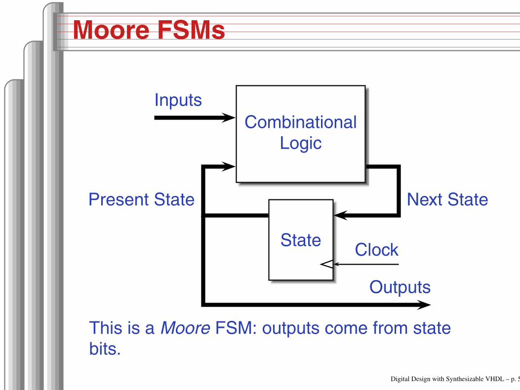
Moore FSMs
State
CombinationalLogic
Clock
Next StatePresent State
Inputs
Outputs
This is a Moore FSM: outputs come from statebits.
Digital Design with Synthesizable VHDL – p. 58

Coding Moore State Machines
library ieee; use ieee.std_logic_1164.all;
entity threecount is
port(clk, reset, count : in std_logic; at0 : out std_logic);
end threecount;
architecture moore of threecount is
type states is (ZERO, ONE, TWO); States encoded automatically
begin
process (clk)
variable state : states;
begin
if rising_edge(clk) then
if reset = ’1’ then state := ZERO;
else case state is
when ZERO => if count = ’1’ then state := ONE; end if;
when ONE => if count = ’1’ then state := TWO; end if;
when TWO => if count = ’1’ then state := ZERO; end if;
end case;
end if;
if state = ZERO then at0 <= ’1’; else at0 <= ’0’; end if;
end if;
end process; end moore;Digital Design with Synthesizable VHDL – p. 59

Coding Mealy State Machines
architecture mealy of ... is
type states is (IDLE, STATE1, ...);
signal state, next_state : states;
begin
process (clk) Sequential process
begin
if rising_edge(clk) then state <= next_state; end if;
end process;
process (reset, state, i1, i2, ... ) Combinational process
begin
next_state <= state; Default: hold
if reset = ’1’ then
next_state <= IDLE;
else
case state is
when IDLE =>
if i1 = ’1’ then
next_state <= STATE1;
end if;
when STATE1 =>Digital Design with Synthesizable VHDL – p. 60

The Traffic Light Controller
ca
rs
ca
rs
This controls a traffic light at
the intersection of a busy highway
and a farm road. Normally,
the highway light is green but if
a sensor detects a car on the farm
road, the highway light turns yellow then red. The
farm road light then turns green until there are no
cars or after a long timeout. Then, the farm road light
turns yellow then red, and the highway light returns to
green. The inputs to the machine are the car sensor,
a short timeout signal, and a long timeout signal. The
outputs are a timer start signal and the colors of the
highway and farm road lights.
Source: Mead and Conway, Introduction to VLSI Systems, 1980, p. 85.Digital Design with Synthesizable VHDL – p. 61

FSM for the Traffic Light Controller
HG HY
FGFY
C + L
CL/T
S
S/T
CL
C + L/T
S
S/T
C: Car sensorS: Short timeoutL: Long timeout
T: Start timer
St Hwy Farm
HG G R
HY Y R
FG R G
FY R YDigital Design with Synthesizable VHDL – p. 62

Traffic Light Controller in VHDL
library ieee;
use ieee.std_logic_1164.all;
entity tlc is
port (clk, reset : in std_logic;
cars, short, long : in std_logic;
highway_yellow, highway_red : out std_logic;
farm_yellow, farm_red : out std_logic;
start_timer : out std_logic);
end tlc;
architecture imp of tlc is
type states is (HG, HY, FY, FG);
signal state, next_state : states;
begin
process (clk) Sequential process
begin
if rising_edge(clk) then
state <= next_state;
end if;
end process; Digital Design with Synthesizable VHDL – p. 63

TLC in VHDL, continued
process (state, reset, cars, short, long)
begin
if reset = ’1’ then
start_timer <= ’1’; next_state <= HG;
else
case state is
when HG =>
highway_yellow <= ’0’; highway_red <= ’0’;
farm_yellow <= ’0’; farm_red <= ’1’;
if cars = ’1’ and long = ’1’ then
start_timer <= ’1’; next_state <= HY;
else start_timer <= ’0’; next_state <= HG;
end if;
when HY =>
highway_yellow <= ’1’; highway_red <= ’0’;
farm_yellow <= ’0’; farm_red <= ’1’;
if short = ’1’ then
start_timer <= ’1’; next_state <= FG;
else start_timer <= ’0’; next_state <= HY;
end if; Digital Design with Synthesizable VHDL – p. 64
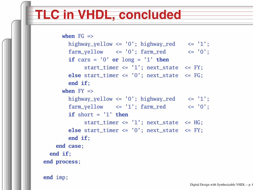
TLC in VHDL, concluded
when FG =>
highway_yellow <= ’0’; highway_red <= ’1’;
farm_yellow <= ’0’; farm_red <= ’0’;
if cars = ’0’ or long = ’1’ then
start_timer <= ’1’; next_state <= FY;
else start_timer <= ’0’; next_state <= FG;
end if;
when FY =>
highway_yellow <= ’0’; highway_red <= ’1’;
farm_yellow <= ’1’; farm_red <= ’0’;
if short = ’1’ then
start_timer <= ’1’; next_state <= HG;
else start_timer <= ’0’; next_state <= FY;
end if;
end case;
end if;
end process;
end imp;
Digital Design with Synthesizable VHDL – p. 65

Summary of the Three
Modeling Styles
Digital Design with Synthesizable VHDL – p. 66
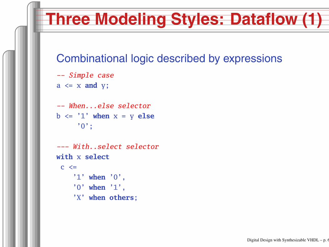
Three Modeling Styles: Dataflow (1)
Combinational logic described by expressions
Simple case
a <= x and y;
When...else selector
b <= ’1’ when x = y else
’0’;
With..select selector
with x select
c <=
’1’ when ’0’,
’0’ when ’1’,
’X’ when others;
Digital Design with Synthesizable VHDL – p. 67

Procedural Combinational (2)
Combinational logic described by statements andexpressions
process (x, y) Should be sensitive to every signal it reads
begin
a <= x and y;
if x = y then
b <= ’1’;
else
b <= ’0’;
end if;
case x of
’0’ => c <= ’1’;
’1’ => c <= ’0’;
others => c <= ’X’;
end case;
end process;
Digital Design with Synthesizable VHDL – p. 68

Three Styles: Procedural Sequential (3)
Combinational logic driving flip-flops described bystatements and expressions.
process (clk) Sensitive only to the clock
begin
if rising_edge(clk) then Always check for rising edge
a <= x and y;
if x = y then
b <= ’1’;
else
b <= ’0’;
end if;
case x of
’0’ => c <= ’1’;
’1’ => c <= ’0’;
others => c <= ’X’;
end case;
end if;
end process; Digital Design with Synthesizable VHDL – p. 69

Ten Commandments of VHDL
Digital Design with Synthesizable VHDL – p. 70

I: Thou Shalt Design Before Coding
Know the structure of what you aredesigning first.
Draw a block diagram of the datapath
Understand the timing (draw diagrams)
Draw bubble-and-arc diagrams for FSMs
Only once you have a design should youstart coding in VHDL
VHDL is only a way to ask for component
Digital Design with Synthesizable VHDL – p. 71

Block Diagram of a Character Gen.
Char.
RAM
2.5K
Font
RAM
1.5K
Controller
Shift Register
Dout
Din
Addr
VSYNC
HSYNC
Video
BLA
NK
Load/S
hift
Digital Design with Synthesizable VHDL – p. 72

Pixel-Level Timing
Clk ��������������������������
CharAddr VVVV�VVVVVVVVVVVVVVVVVVVVVVVVVVVVVV�VVVVVVVVVVVVVVi−1 i i+1
LoadChar LLLL�HH�LLLLLLLLLLLLLLLLLLLLLLLLLL�HH�LLLLLLLLLL
CharData VVVVVVVV�VVVVVVVVVVVVVVVVVVVVVVVVVVVVVV�VVVVVVVVVVi−1 i
FontLoad LLLLLLLL�HH�LLLLLLLLLLLLLLLLLLLLLLLLLL�HH�LLLLLL
PixelData VVVVVVVVVVVV�VVVVVVVVVVVVVVVVVVVVVVVVVVVVVV�VVVVVVi−1 i
Load/Shift LLLLLLLLLLLL�HH�LLLLLLLLLLLLLLLLLLLLLLLLLL�HH�LL
Bit �VV�VV�VV�VV�VV�VV�VV�VV�VV�VV�VV�VV�VV3 2 1 0 7 6 5 4 3 2 1Digital Design with Synthesizable VHDL – p. 73

Start-of-line Detail
140 141 142 143 144 145 146 147 148 149 150
Clk ��������������������������
Hcount �VV�VV�VV�VV�VV�VV�VV�VV�VV�VV�VV�VV�VV
Column UUUU�VVVVVVVVVVVVVVVVVVVVVVVVVVVVVV�VVVVVVVVVVVVVV0 1
LoadChar LLLL�HH�LLLLLLLLLLLLLLLLLLLLLLLLLL�HH�LLLLLLLLLL
CharData UUUUUUUU�VVVVVVVVVVVVVVVVVVVVVVVVVVVVVV�VVVVVVVVVV0
FontLoad LLLLLLLL�HH�LLLLLLLLLLLLLLLLLLLLLLLLLL�HH�LLLLLL
PixelData UUUUUUUUUUUU�VVVVVVVVVVVVVVVVVVVVVVVVVVVVVV�VVVVVV0
Load/Shift LLLLLLLLLLLL�HH�LLLLLLLLLLLLLLLLLLLLLLLLLL�HH�LL
HBLANK LLLLLLLLLLLLLLLL�HHHHHHHHHHHHHHHHHHHHHHHHHHHHHHHHHH
Pixel UUUUUUUUUUUUUUUU�VV�VV�VV�VV�VV�VV�VV�VV�VV
Digital Design with Synthesizable VHDL – p. 74
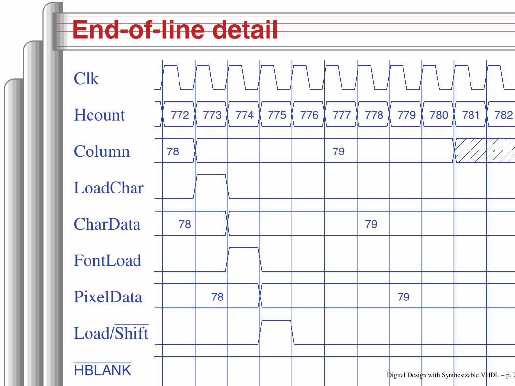
End-of-line detail
772 773 774 775 776 777 778 779 780 781 782
Clk ��������������������������
Hcount �VV�VV�VV�VV�VV�VV�VV�VV�VV�VV�VV�VV�VV
Column VVVV�VVVVVVVVVVVVVVVVVVVVVVVVVVVVVV�UUUUUUUUUUUUUU78 79
LoadChar LLLL�HH�LLLLLLLLLLLLLLLLLLLLLLLLLLLLLLLLLLLLLLLLLL
CharData VVVVVVVV�VVVVVVVVVVVVVVVVVVVVVVVVVVVVVVVVVVVVVVVVVV78 79
FontLoad LLLLLLLL�HH�LLLLLLLLLLLLLLLLLLLLLLLLLLLLLLLLLLLLLL
PixelData VVVVVVVVVVVV�VVVVVVVVVVVVVVVVVVVVVVVVVVVVVVVVVVVVVV78 79
Load/Shift LLLLLLLLLLLL�HH�LLLLLLLLLLLLLLLLLLLLLLLLLLLLLLLLLL
HBLANK HHHHHHHHHHHHHHHHHHHHHHHHHHHHHHHHHHHHHHHHHHHHHHHH�LL
Pixel �VV�VV�VV�VV�VV�VV�VV�VV�VV�VV�VV�VV�UU
Digital Design with Synthesizable VHDL – p. 75
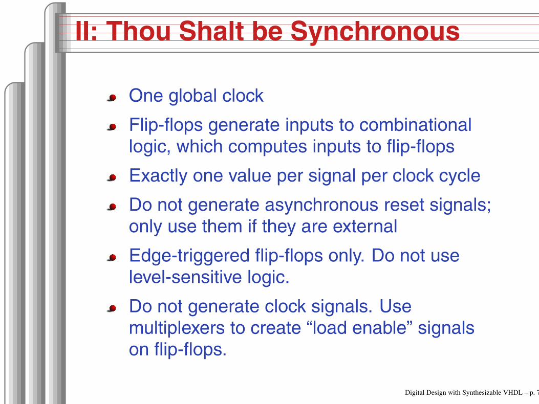
II: Thou Shalt be Synchronous
One global clock
Flip-flops generate inputs to combinationallogic, which computes inputs to flip-flops
Exactly one value per signal per clock cycle
Do not generate asynchronous reset signals;only use them if they are external
Edge-triggered flip-flops only. Do not uselevel-sensitive logic.
Do not generate clock signals. Usemultiplexers to create “load enable” signalson flip-flops.
Digital Design with Synthesizable VHDL – p. 76

III: Thou Shalt Be Sensitive
Combinational processes: list all process inputs
process (state, long)
begin
if reset = ’1’ then
next_state <= HG;
start_timer <= ’1’;
else
case state is
when HG =>
farm_yellow <= ’0’;
if cars = ’1’ and long = ’1’ then
next_state <= HY;
else
next_state <= HG;
end if;
when HY =>
farm_yellow <= ’0’;
if short = ’1’ then
next_state <= FG;
else
next_state <= HY;
end if;
process (state, reset, cars, short, long)
begin
if reset = ’1’ then
next_state <= HG;
start_timer <= ’1’;
else
case state is
when HG =>
farm_yellow <= ’0’;
if cars = ’1’ and long = ’1’ then
next_state <= HY;
else
next_state <= HG;
end if;
when HY =>
farm_yellow <= ’0’;
if short = ’1’ then
next_state <= FG;
else
next_state <= HY;
end if;Digital Design with Synthesizable VHDL – p. 77

III: Thou Shalt Be Sensitive
Sequential processes: always include the clock.Include reset if asynchronous, and nothing else.
process (Clk, D)
begin
if rising_edge(Clk) then
Q <= D;
end if;
end process;
process (Clk, D)
begin
if reset = ’1’ then
Q <= ’0’;
else
if rising_edge(Clk) then
Q <= D;
end if;
end if;
end process;
process (Clk)
begin
if rising_edge(Clk) then
Q <= D;
end if;
end process;
process (Clk, reset)
begin
if reset = ’1’ then
Q <= ’0’;
else
if rising_edge(Clk) then
Q <= D;
end if;
end if;
end process;
Digital Design with Synthesizable VHDL – p. 78

IV: Thou Shalt Assign All Outputs
Synthesis infers level-sensitive latches ifsometimes you do not assign an output.
process (state, input)
begin
case state is
when S1 =>
if input = ’1’ then
output <= ’0’;
end if;
when S2 =>
output <= ’1’;
end case;
end process;
process (state, input)
begin
case state is
when S1 =>
if input = ’1’ then
output <= ’0’;
else
output <= ’1’;
end if;
when S2 =>
output <= ’1’;
end case;
end process;
Digital Design with Synthesizable VHDL – p. 79
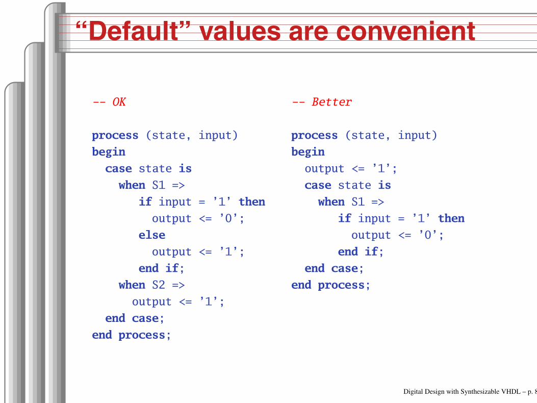
“Default” values are convenient
OK
process (state, input)
begin
case state is
when S1 =>
if input = ’1’ then
output <= ’0’;
else
output <= ’1’;
end if;
when S2 =>
output <= ’1’;
end case;
end process;
Better
process (state, input)
begin
output <= ’1’;
case state is
when S1 =>
if input = ’1’ then
output <= ’0’;
end if;
end case;
end process;
Digital Design with Synthesizable VHDL – p. 80
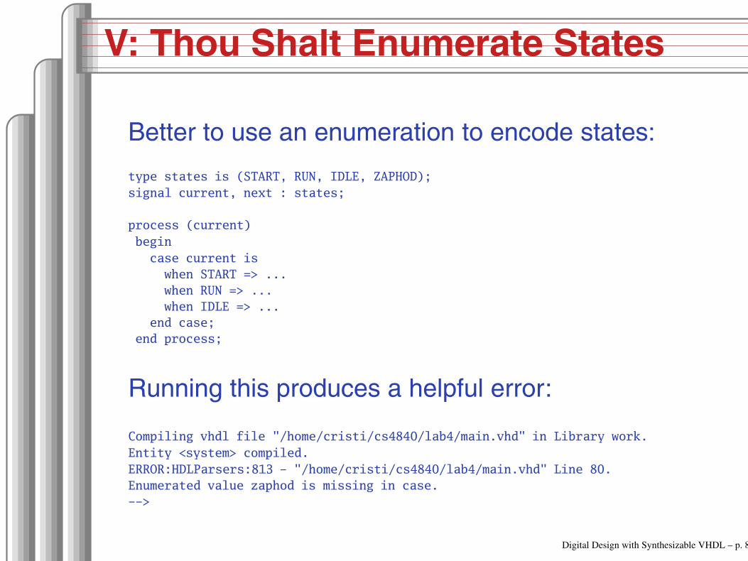
V: Thou Shalt Enumerate States
Better to use an enumeration to encode states:
type states is (START, RUN, IDLE, ZAPHOD);
signal current, next : states;
process (current)
begin
case current is
when START => ...
when RUN => ...
when IDLE => ...
end case;
end process;
Running this produces a helpful error:
Compiling vhdl file "/home/cristi/cs4840/lab4/main.vhd" in Library work.
Entity <system> compiled.
ERROR:HDLParsers:813 "/home/cristi/cs4840/lab4/main.vhd" Line 80.
Enumerated value zaphod is missing in case.
>
Digital Design with Synthesizable VHDL – p. 81

VI:
(There is no rule six)
Digital Design with Synthesizable VHDL – p. 82

VII: Thou Shalt Avoid Async
Only use asynchronous reset when there is oneglobal signal from outside.
OK for external Reset
process (Clk, Reset)
begin
if Reset = ’1’ then
Q <= ’0’;
else
if rising_edge(Clk) then
Q <= D;
end if;
end if;
end process;
Better
process (Clk)
begin
if rising_edge(Clk) then
if Reset = ’1’ then
Q <= ’0’;
else
Q <= D;
end if;
end if;
end process;
Never generate your own asynchronous reset.Generating a synchronous reset is fine
Digital Design with Synthesizable VHDL – p. 83

VIII: Thou Shalt Have One Version
Never assume signals from the test benchthat are not there on the board
It is hard enough to make simulation matchthe design; do not make it any harder
If you must slow down hardware, carefullygenerate a slower clock and only use thatclock globally.
Digital Design with Synthesizable VHDL – p. 84
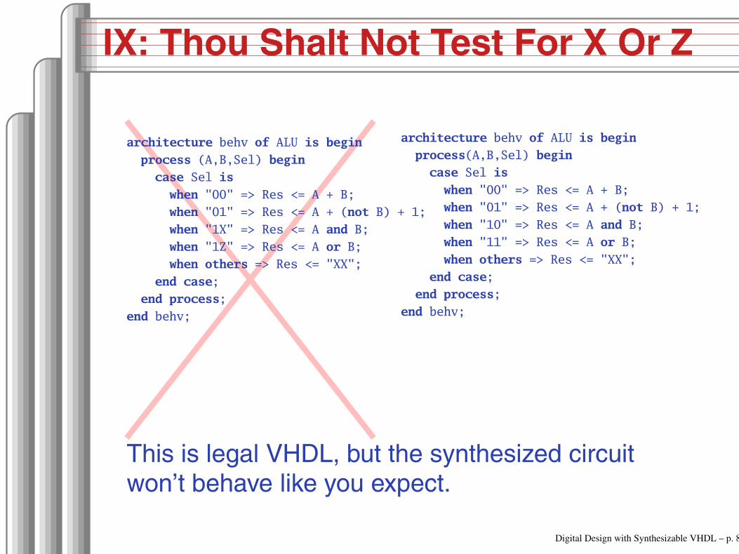
IX: Thou Shalt Not Test For X Or Z
architecture behv of ALU is begin
process (A,B,Sel) begin
case Sel is
when "00" => Res <= A + B;
when "01" => Res <= A + (not B) + 1;
when "1X" => Res <= A and B;
when "1Z" => Res <= A or B;
when others => Res <= "XX";
end case;
end process;
end behv;
architecture behv of ALU is begin
process(A,B,Sel) begin
case Sel is
when "00" => Res <= A + B;
when "01" => Res <= A + (not B) + 1;
when "10" => Res <= A and B;
when "11" => Res <= A or B;
when others => Res <= "XX";
end case;
end process;
end behv;
This is legal VHDL, but the synthesized circuitwon’t behave like you expect.
Digital Design with Synthesizable VHDL – p. 85

X: Thou Shalt Not Specify Delays
The wait statement can delay for a certainamount of time, e.g., “wait 10ns;”
Only use it in test benches that are notmeant to become hardware
Do not use them in the design of yourhardware
Digital Design with Synthesizable VHDL – p. 86

Pitfalls: Boolean vs. Std_logic
Don’t assign Boolean to std_logic.
signal a : std_logic;
signal b : unsigned(7 downto 0);
a <= b = x"7E"; BAD: result is Boolean, not std_logic
a <= ’1’ when b = x"7E" else ’0’; OK
Don’t test std_logic in a Boolean context.
signal a, b, foo : std_logic;
if a then BAD: A is not Boolean
foo <= ’1’;
end if;
b <= ’0’ when a else ’1’; BAD: a is not Boolean
if a = ’1’ then OK
foo <= ’1’;
end if;
Digital Design with Synthesizable VHDL – p. 87

Pitfalls: Inferring a Latch
In a combinational process, make sure all outputsignals are always assigned.
process (x, y)
begin
if x = ’1’ then
y <= ’0’;
end if;
BAD: y not assigned when x = ’0’, synthesis infers a latch
end process;
process (x, y)
begin
y <= ’1’; OK: y is always assigned
if x = ’1’ then
y <= ’0’;
end if;
end processDigital Design with Synthesizable VHDL – p. 88

Pitfalls: Reading Output Port
library ieee;
use ieee.std_logic_1164.all;
entity dont_read_output is
port ( a : in std_logic;
x, y : out std_logic );
end dont_read_output;
architecture BAD of dont_read_output is
begin
x <= not a;
y <= not x; Error: can’t read an output port
end BAD;
architecture OK of dont_read_output is
signal x_sig : std_logic;
begin
x_sig <= not a;
x <= x_sig; x_sig just another name for x
y <= not x_sig; OK
end OK; Digital Design with Synthesizable VHDL – p. 89

Pitfalls: Complex Port Map Args
library ieee;
use ieee.std_logic_1164.all;
use ieee.numeric_std.all;
entity bad_port_map is end bad_port_map;
architecture BAD of bad_port_map is
component bar port (x : in unsigned(5 downto 0) ); end component;
signal a : unsigned(3 downto 0);
begin
mybar : bar port map ( x => "000" & a); BAD
end BAD;
architecture OK of bad_port_map is
component bar port (x : in unsigned(5 downto 0) ); end component;
signal a : unsigned(3 downto 0);
signal aa : unsigned(5 downto 0);
begin
aa <= "000" & a;
mybar : bar port map ( x => aa ); OK
end OK; Digital Design with Synthesizable VHDL – p. 90

Pitfalls: Combinational Loops
You never really need them.
Drive every signal from exactly one process orconcurrent assignment.
Don’t build SR latches. Use D flip-flops instead.
Digital Design with Synthesizable VHDL – p. 91

Pitfalls: Clock Gating
Dangerous, difficult to get right.
Use a single, global clock and latch enables toperform the same function.
Digital Design with Synthesizable VHDL – p. 92

Pitfalls: Multiple Clock Domains
If you must, vary the phase and drive clocksdirectly from flip-flops.
Digital Design with Synthesizable VHDL – p. 93

Writing Testbenches
Digital Design with Synthesizable VHDL – p. 94

Testbenches
One of VHDL’s key points: can describe hardwareand environment together.
Explicit delays are allowed
clk <= not clk after 50 ns;
process
begin
reset <= ’0’;
wait for 10 ns; Explicit delay
reset <= ’1’;
wait for a = ’1’; Delay for an event
assert b = ’1’ report "b did not rise" severity failure;
assert c = ’1’ report "c=0" severity warning; or error or note
wait for 50 ns; Delay for some time
wait; Halt this process
end process;
Digital Design with Synthesizable VHDL – p. 95
Testbench Methodology
Always put testbench in a separate .vhd filesince it cannot be synthesized.
Instantiate block under test and applydesired inputs (clocks, other stimulus)
Use assert to check conditions
Try to emulate hardware environment asclosely as possible (no special inputs, etc.)
Digital Design with Synthesizable VHDL – p. 96

A Testbench
library ieee;
use ieee.std_logic_1164.all;
use ieee.numeric_std.all;
entity tlc_tb is A testbench usually has no ports
end tlc_tb;
architecture tb of tlc_tb is
signal clk : std_logic := ’0’; Must initialize!
One signal per port is typical
signal reset, cars, short, long : std_logic;
signal farm_red, start_timer : std_logic;
begin
clk <= not clk after 34.92 ns; 14 MHz
Digital Design with Synthesizable VHDL – p. 97
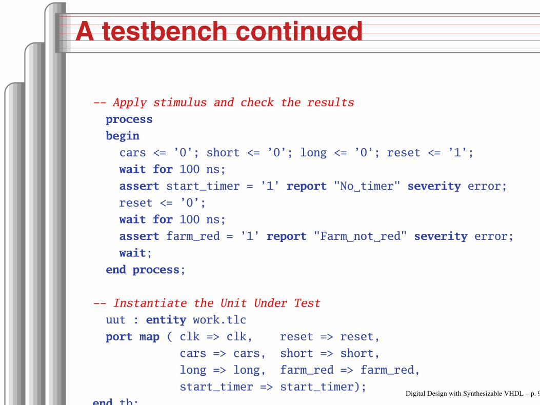
A testbench continued
Apply stimulus and check the results
process
begin
cars <= ’0’; short <= ’0’; long <= ’0’; reset <= ’1’;
wait for 100 ns;
assert start_timer = ’1’ report "No timer" severity error;
reset <= ’0’;
wait for 100 ns;
assert farm_red = ’1’ report "Farm not red" severity error;
wait;
end process;
Instantiate the Unit Under Test
uut : entity work.tlc
port map ( clk => clk, reset => reset,
cars => cars, short => short,
long => long, farm_red => farm_red,
start_timer => start_timer);
end tb;Digital Design with Synthesizable VHDL – p. 98


