Digital Fabrication of 3D Bio Devices Utilizing PELID (Pattern-ing with Electrostatically-Injected Droplet) Method Shinjiro Umezu1,2, Tatsuru Hatta1,2, Hitoshi Ohmori2; 1Tokai University; 4-1-1, Kitakaname, Hiratsuka-shi, Kanagawa/Japan, 2Riken; 2-1, Hirosawa, Wako-shi, Saitama/Japan
Abstract
In this paper, we fabricated soft 3D bio devices utilizing PELID (Patterning with Electrostatically-Injected Droplet) meth-od. It is preferable to perform laboratory experiments with 3D structures in bioengineering. We have investigated mechanism and fundamental characteristics of the PELID method and now been applying for new printing technology of high image quality and 3D printing technology. The method has two merits, higher resolution than commercial printer and ability to eject with highly viscous liquid. We can eject viscous paste that viscosity is 30000 mPas. At DF 2010, I already presented that cells and scaffolds were printed to fabricate 3D cell structures because scaffolds assisted the weight of cells. Now, we should fabricate 3D structure that has cave because real 3D structure has blood vessel like cave. It is dif-ficult to fabricate 3D structure that has cave. Gelatin is used as sacrificial layer. When the printed 3D structure is put into hot wa-ter, gelatin is removed. With this technique, we can print 3D struc-ture that has cave. The tube filled with the liquid that contained gelatin and the tube filled with the liquid that contained calcium alginate was hanged down perpendicular to a dish. Voltage was applied between the syringes and the dish by power supplies (volt-age range: -5kV ~ +5kV, Matsusada Precision Inc, Tokyo, HVR-10P). The air gap was adjusted by a z-stage and the plate elec-trode was moved in x and y directions with two linear motors. PC controlled voltage application and motion of linear stages. We fabricated 3D bio devices.
Introduction The goal of this study is to fabricate precision 3-Dimensional cell structures utilizing PELID (Patterning with ELectrostatically-Injected Droplet) method. It is preferable to perform laboratory experiments with 3D cell structures in tissue engineering and arti-ficial organ. However it is difficult to fabricate 3D cell structures because own weight of cell is above the bonding force between cells. Many researchers carried out studies on Bio-print. 3D posi-tioning of calcium alginate that contained living cells utilizing commercial inkjet was succeed [1, 2]. The papers described that calcium alginate was used as scaffolds. Calcium alginate is useful to fabricate 3 Dimensional structures because the stiffness is rela-tively high. We applied the PELID method for patterning living cells and scaffolds to fabricate 3D cell structures [3, 4]. Our inkjet technology, PELID method, has two merits; those are high resolu-tion and ability to eject highly viscous liquid. These merits are suitable to print cells precisely and eject highly viscous scaffolds. Bone stem cells [3] and MDCK cells [4] were printed utilizing the PELID method. We utilize collagen and/or gelatin as scaffolds to
fabricate 3D cell structures because collagen and gelatin are most often-used scaffolds in vivo. However, the height of the fabricated 3D structures was low because the stiffness was low in case that collagen and gelatin was used as scaffolds. To clear this problem, we plan to print calcium alginate that supports collagen. In this pa-per, we investigate fundamental characteristics to print calcium al-ginate and optimize the print condition to fabricate high 3D cell structures.
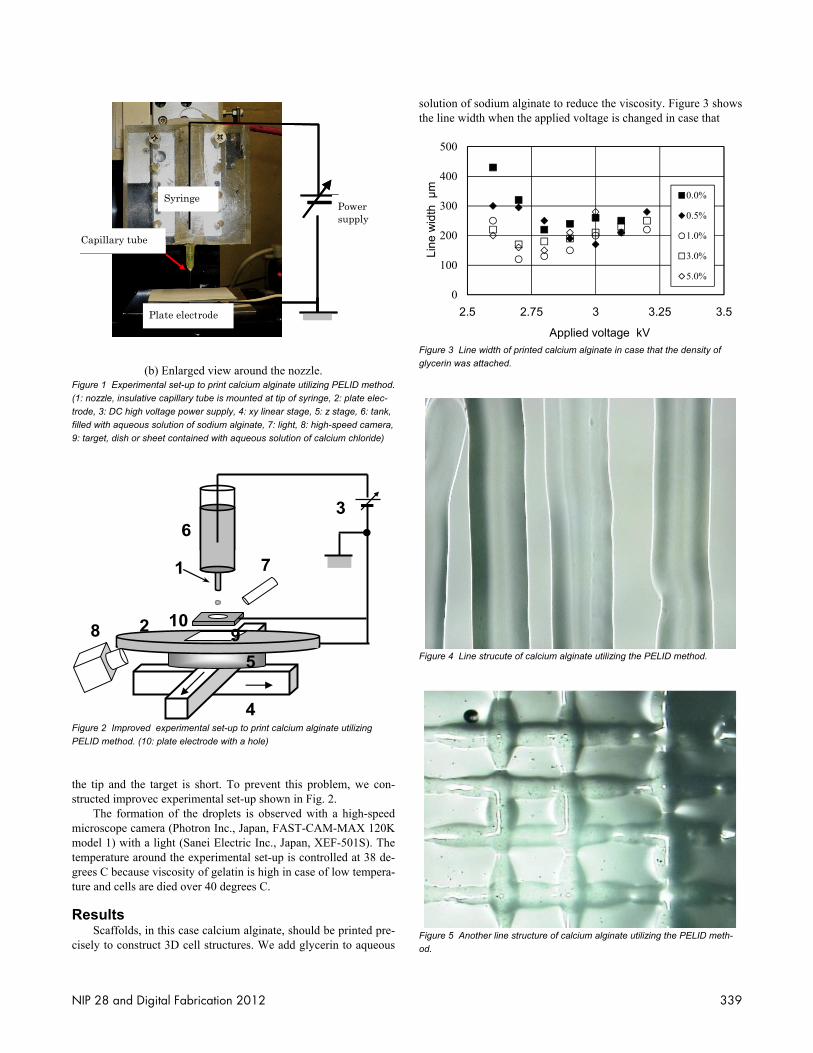
Experimental Set-up An experimental set-up shown in Fig.1 is constructed to inves-tigate characteristics to print calcium alginate utilizing the PELID method. Figure 1 (b) shows the enlarged view around the nozzle. Calcium alginate is produced when high voltage is applied be-tween nozzle that is filled with aqueous solution of sodium algi-nate and target that is slightly filled with aqueous solution of cal-cium chloride. The nozzle is hanged down perpendicular to the target. Voltage is applied between the nozzle and the target by a power supply (voltage range: -5kV ~ +5kV, Matsusada Precision Inc, Tokyo, HVR-10P). The air gap is adjusted by a z-stage and the dish is moved in x and y directions with two linear motors. A PC controls voltage application and motion of the linear stages. When the printed 3D structure is high, the electric field around the tip of the nozzle is relatively weak because the air gap between
Figure 1 Experimental set-up to print calcium alginate utilizing PELID method. (1: nozzle, insulative capillary tube is mounted at tip of syringe, 2: plate elec-trode, 3: DC high voltage power supply, 4: xy linear stage, 5: z stage, 6: tank, filled with aqueous solution of sodium alginate, 7: light, 8: high-speed camera, 9: target, dish or sheet contained with aqueous solution of calcium chloride)
1
3
4
2
3
5
6
7
8 9 10
Figure 2 Improved experimental set-up to print calcium alginate utilizing PELID method. (10: plate electrode with a hole)
the tip and the target is short. To prevent this problem, we con-structed improvec experimental set-up shown in Fig. 2. The formation of the droplets is observed with a high-speed microscope camera (Photron Inc., Japan, FAST-CAM-MAX 120K model 1) with a light (Sanei Electric Inc., Japan, XEF-501S). The temperature around the experimental set-up is controlled at 38 de-grees C because viscosity of gelatin is high in case of low tempera-ture and cells are died over 40 degrees C.
Results Scaffolds, in this case calcium alginate, should be printed pre-cisely to construct 3D cell structures. We add glycerin to aqueous
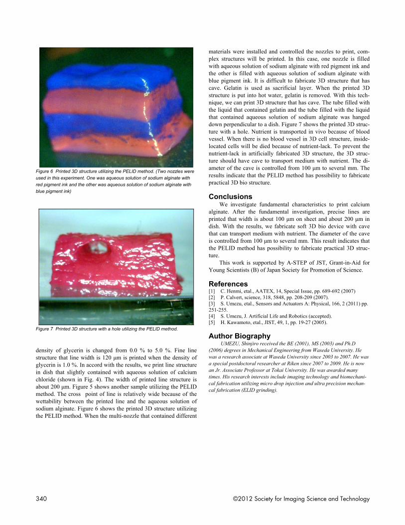
solution of sodium alginate to reduce the viscosity. Figure 3 shows the line width when the applied voltage is changed in case that
0
100
200
300
400
500
2.5 2.75 3 3.25 3.5
Line
wid
th μ
m
Applied voltage kV
0.0%
0.5%
1.0%
3.0%
5.0%
Figure 3 Line width of printed calcium alginate in case that the density of glycerin was attached.
Figure 4 Line strucute of calcium alginate utilizing the PELID method.
Figure 5 Another line structure of calcium alginate utilizing the PELID meth-od.
NIP 28 and Digital Fabrication 2012 339
Figure 6 Printed 3D structure utilizing the PELID method. (Two nozzles were used in this experiment. One was aqueous solution of sodium alginate with red pigment ink and the other was aqueous solution of sodium alginate with blue pigment ink)
Figure 7 Printed 3D structure with a hole utilizing the PELID method.
density of glycerin is changed from 0.0 % to 5.0 %. Fine line structure that line width is 120 μm is printed when the density of glycerin is 1.0 %. In accord with the results, we print line structure in dish that slightly contained with aqueous solution of calcium chloride (shown in Fig. 4). The width of printed line structure is about 200 μm. Figure 5 shows another sample utilizing the PELID method. The cross point of line is relatively wide because of the wettability between the printed line and the aqueous solution of sodium alginate. Figure 6 shows the printed 3D structure utilizing the PELID method. When the multi-nozzle that contained different
materials were installed and controlled the nozzles to print, com-plex structures will be printed. In this case, one nozzle is filled with aqueous solution of sodium alginate with red pigment ink and the other is filled with aqueous solution of sodium alginate with blue pigment ink. It is difficult to fabricate 3D structure that has cave. Gelatin is used as sacrificial layer. When the printed 3D structure is put into hot water, gelatin is removed. With this tech-nique, we can print 3D structure that has cave. The tube filled with the liquid that contained gelatin and the tube filled with the liquid that contained aqueous solution of sodium alginate was hanged down perpendicular to a dish. Figure 7 shows the printed 3D struc-ture with a hole. Nutrient is transported in vivo because of blood vessel. When there is no blood vessel in 3D cell structure, inside-located cells will be died because of nutrient-lack. To prevent the nutrient-lack in artificially fabricated 3D structure, the 3D struc-ture should have cave to transport medium with nutrient. The di-ameter of the cave is controlled from 100 μm to several mm. The results indicate that the PELID method has possibility to fabricate practical 3D bio structure.
Conclusions We investigate fundamental characteristics to print calcium alginate. After the fundamental investigation, precise lines are printed that width is about 100 μm on sheet and about 200 μm in dish. With the results, we fabricate soft 3D bio device with cave that can transport medium with nutrient. The diameter of the cave is controlled from 100 μm to several mm. This result indicates that the PELID method has possibility to fabricate practical 3D struc-ture. This work is supported by A-STEP of JST, Grant-in-Aid for Young Scientists (B) of Japan Society for Promotion of Science.
References [1] C. Henmi, etal., AATEX, 14, Special Issue, pp. 689-692 (2007) [2] P. Calvert, science, 318, 5848, pp. 208-209 (2007). [3] S. Umezu, etal., Sensors and Actuators A: Physical, 166, 2 (2011) pp. 251-255. [4] S. Umezu, J. Artificial Life and Robotics (accepted). [5] H. Kawamoto, etal., JIST, 49, 1, pp. 19-27 (2005).
Author Biography UMEZU, Shinjiro received the BE (2001), MS (2003) and Ph.D
(2006) degrees in Mechanical Engineering from Waseda University. He was a research associate at Waseda University since 2003 to 2007. He was a special postdoctoral researcher at Riken since 2007 to 2009. He is now an Jr. Associate Professor at Tokai University. He was awarded many times. His research interests include imaging technology and biomechani-cal fabrication utilizing micro drop injection and ultra precision mechan-cal fabrication (ELID grinding).