16
Digital Gauge Fluid Reservoirs Operating Manual Electronic pdf files of Nordson EFD manuals are also available at www.nordsonefd.com ™

Digital Gauge Fluid ReservoirsOperating Manual
Electronic pdf files of Nordson EFD manuals are also available at www.nordsonefd.com
™
Digital Gauge Fluid Reservoirs
2 www.nordsonefd.com [email protected] +1-401-431-7000 Sales and service of Nordson EFD dispensing systems are available worldwide.
ContentsContents ..........................................................................................................................................................................2Safety Warnings ..............................................................................................................................................................3
Halogenated Hydrocarbon Fluid Hazard .....................................................................................................................3Pressurized Equipment Hazard ...................................................................................................................................3Equipment Misuse Hazard ...........................................................................................................................................3Personal Protective Equipment ...................................................................................................................................3System Pressure ..........................................................................................................................................................3Fluid Compatibility .......................................................................................................................................................3Fill Level .......................................................................................................................................................................3Tipping and Dropping Hazard .....................................................................................................................................4Tubing Safety ...............................................................................................................................................................4
1-Liter Tank Specifications ..............................................................................................................................................55-Liter Tank Specifications ..............................................................................................................................................5Pressure Relief Procedure ...............................................................................................................................................6Digital Gauge Operation ..................................................................................................................................................8Zeroing the Gauge ...........................................................................................................................................................8Setup ...............................................................................................................................................................................9Refilling ..........................................................................................................................................................................10Battery Replacement .....................................................................................................................................................11Wetted Materials List .....................................................................................................................................................11Maintenance and Cleaning ............................................................................................................................................11Part Numbers ................................................................................................................................................................12Accessories ...................................................................................................................................................................121-Liter Tank Replacement Parts ....................................................................................................................................135-Liter Tank Replacement Parts ....................................................................................................................................14Troubleshooting ............................................................................................................................................................15

Digital Gauge Fluid Reservoirs
3www.nordsonefd.com [email protected] +1-401-431-7000 Sales and service of Nordson EFD dispensing systems are available worldwide.
Safety Warnings
Halogenated Hydrocarbon Fluid HazardNEVER USE halogenated hydrocarbon solvents or fluids containing such solvents in this equipment. Examples of halogenated hydrocarbon solvents are: 1,1,1 trichloroethane, methylene chloride, fluids with the prefix “fluoro-”, “chloro-”, “bromo-” or “iodo-”, etc. These solvents can cause an explosion when used with aluminum components in a pressurized fluid pumping system. The resulting explosion may cause death, serious bodily injury or substantial property damage.
Pressurized Equipment HazardHigh pressure fluid can cause serious injury. This equipment is for professional use only. Observe all warnings. Read and understand all applicable instruction manuals before placing equipment into service.
Equipment Misuse HazardGENERAL SAFETY — Any use of the reservoir and related accessories not consistent with that described in this manual, such as modifying or removing parts, over-pressurizing, using incompatible fluids and chemicals, or using worn, damaged or incompatible parts can cause them to rupture resulting in serious bodily injury, including fluid splashed in the eyes or on the skin, or fire, explosion or other property damage.
NEVER alter or modify any part of this equipment, as doing so may cause it to malfunction.
CHECK all reservoir components regularly and replace any worn or damaged parts with only EFD supplied or approved parts. BE SURE that all dispensing equipment and accessories are rated to withstand the maximum operating pressure of the reservoir.
Personal Protective EquipmentWear all protective eyewear, gloves, clothing, and respirator as recommended by the manufacturer of the fluid used.
System PressureNEVER exceed the maximum reservoir pressure of 7.0 bar (100 psi). The maximum supply pressure to the reservoir regulator must not exceed 10.4 bar (150 psi).
BE SURE that all dispensing equipment and accessories are rated to withstand the maximum operating pressure of the reservoir.
If an EFD five-micron filter regulator #7002002 is not used, be certain your plant air is properly filtered and dry. Oil or particulate in the air supply line can cause erratic performance and can contaminate the fluid to be dispensed if it is not properly filtered.
Fluid CompatibilityBE SURE that all fluids, including their vapors, contained in the reservoir are compatible with all materials on the wetted materials list on page 11 of this manual. Read the fluid manufacturer’s literature, including the SDS (Safety Data Sheet) and observe all warnings before pouring the fluid into the reservoir.
Fill LevelDO NOT overfill the reservoir. The recommended maximum fill level is 38.1 mm (1.5") below the top of the liner.

Digital Gauge Fluid Reservoirs
4 www.nordsonefd.com [email protected] +1-401-431-7000 Sales and service of Nordson EFD dispensing systems are available worldwide.
Tipping and Dropping HazardBE SURE that the reservoir is placed on a hard, level surface and that all tubing lengths are of sufficient length to allow free motion of all movable components attached to the reservoir. DO NOT pull on tubing to move the reservoir.
Tipping the reservoir or otherwise supporting it on its side can cause fluid to enter both the pressure regulator and pressure relief valve and interfere with their normal function.
A damaged pressure regulator and/or damaged pressure relief valve may lead to an over-pressure condition within the reservoir. If the reservoir tips or the pressure regulator and/or pressure relief valve otherwise become blocked, they must be replaced with EFD supplied or approved parts before returning to service.
Dropping the reservoir from any height can damage the pressure regulator, pressure relief valve, and fittings and/or compromise the integrity of the reservoir body and cover. A damaged pressure regulator and/or damaged pressure relief valve may lead to an over-pressure condition within the reservoir. A damaged reservoir body and/or cover can be an explosion hazard. If the reservoir falls from any height, it must be thoroughly inspected for cracks or damage to the pressure regulator and/or pressure relief valve. If damage to a component is suspected, it must be replaced with EFD supplied or approved parts before returning to service.
Tubing SafetyPressurized tubing can be very dangerous. Tubing whose integrity is compromised due to any kind of wear, damage or misuse can develop a leak, spraying the contents of the tank at high pressure. This spray can enter the eyes or cover the skin or cause other serious bodily injury, fire or property damage.
Before pressurizing the reservoir:
1. BE SURE all fluid connections to the reservoir are properly secured.
2. Examine all tubing for cuts, wear, bulges and leaks. If any of these conditions exist, replace the tubing immediately with EFD supplied or approved tubing. Do not try to repair a damaged tube.
3. BE SURE that the fluid to be dispensed is compatible with the tubing. Contact the fluid manufacturer and confirm that the fluid is compatible with the tubing material specified on page 11 of this manual.
4. BE SURE that the tubing will not be exposed to operating temperatures in excess of 50° C (122° F) or below 0° C (32° F) in the application.
Safety Warnings (continued)

Digital Gauge Fluid Reservoirs
5www.nordsonefd.com [email protected] +1-401-431-7000 Sales and service of Nordson EFD dispensing systems are available worldwide.
1-Liter Tank SpecificationsItem Specification
Capacity 1 L
Maximum operating pressure 7.0 bar (100 psi)
Maximum operating temperature 50° C (122° F)
Weight 3.0 kg (6.6 lb)
Height 350 mm (13.75")
Diameter (cover maximum) 172 mm (6.75")
5-Liter Tank SpecificationsItem Specification
Capacity 5 L
Maximum Operating Pressure 7.0 bar (100 psi)
Maximum Operating Temperature 50° C (122° F)
Weight 9.1 kg (20.1 lb)
Height 413 mm (16.25")
Diameter (Cover Maximum) 251 mm (9.85")
Approvals CE

Digital Gauge Fluid Reservoirs
6 www.nordsonefd.com [email protected] +1-401-431-7000 Sales and service of Nordson EFD dispensing systems are available worldwide.
Pressure Relief ProcedureTo reduce the risk of bodily injury, including fluid splashing into the eyes, NEVER attempt to open the reservoir without first performing this procedure.
1. Slide the shutoff valve on the air input hose to exhaust. (Figure 1)
2. Actuate the air relief valve . Hold the relief valve open until any hissing sounds end.
3. Confirm that the indicated gauge pressure is zero . If the gauge reads zero, slowly release the cover clamps and remove the cover as shown in Figure 2 (page 7).
4. If the pressure gauge does not read zero after performing Steps 1 and 2, remove the air input hose from the air regulator and set the regulator pressure to zero. A hissing sound should be heard from the regulator during this step. Once the gauge reads zero, return to Step 3. Do not use the reservoir until the air relief valve is replaced.
Figure 1. 1 L tank shown
1 3
4Electrical
Constant Air
Fluid
Actuating Air
Air filterregulator
ValveMate 8000controller
Regulated air supply
Actuating air
EFD valves
Air input hose
Fluid feed line
2

Digital Gauge Fluid Reservoirs
7www.nordsonefd.com [email protected] +1-401-431-7000 Sales and service of Nordson EFD dispensing systems are available worldwide.
Pressure Relief Procedure (continued)
Figure 1. 5 L tank shown
Figure 2. Remove the cover
Electrical
Constant Air
Fluid
Actuating Air
1
3
4
Air filterregulator
ValveMate 8000controller
Regulated air supply
Actuating air
EFD valves
Air input hose
Fluid feed line
2

Digital Gauge Fluid Reservoirs
8 www.nordsonefd.com [email protected] +1-401-431-7000 Sales and service of Nordson EFD dispensing systems are available worldwide.
Digital Gauge Operation1. To turn the digital gauge on, push the power button under the PSIG label on the front of the gauge.
2. The display shuts down every five minutes to preserve battery life. To reactivate the display, push the power button.
NOTE: For battery replacement instructions, see page 11.
Zeroing the Gauge1. Remove the zero cover plug from the right side of the Omega digital pressure gauge, labeled Zero.
DO NOT REMOVE COVER PLUG MARKED SPAN.
2. Using the screwdriver provided, turn the exposed screw clockwise to raise the zero point and counterclockwise to lower the zero point. Stop turning when gauge reads 0.00 or 0.0.
3. Reinstall the zero cover plug.
Span set screwDO NOT USEFOR ZEROING
Zero set screw

Digital Gauge Fluid Reservoirs
9www.nordsonefd.com [email protected] +1-401-431-7000 Sales and service of Nordson EFD dispensing systems are available worldwide.
Setup1. Install the input air tee into the EFD five-micron filter regulator supplied with the ValveMate™ controller.
Maximum pressure is 7.0 bar (100 psi). If no air filter regulator is available, specify #7002002. (For cyanoacrylates, add coalescing filter regulator element #7021515.)
2. Set up the Nordson EFD dispense valve and controller as described in their operating manuals.
3. Remove the tank cover and temporarily store it by reattaching one of the clamps (Figure 2). When refilling the tank, use a cup (not included) to catch any excess material that drips from the feed tube.
4. Cut the fluid feed tubing to an appropriate length plus 20.3 cm (8") to go inside the tank. Cut one end of the feed tubing at an angle and push the tubing through the bulkhead fitting and adjust the inside length so it sits just off the bottom of the tank. Tighten the compression nut to secure the tube.
NOTE: 5-Liter Series tank reservoirs can use either 1/4" or 3/8" OD fluid feed tubing. With 1/4" fluid feed tubing, use reducer fitting #7020159 (Figure 4).
5. Attach the other end of the fluid feed tubing to the dispense valve as described in the valve operating manual.
6. Fill the tank either by pouring material directly into the tank liner or by removing the liner and placing a manufacturer’s bottle inside the tank.
7. Install the cover. If you are using a manufacturer’s bottle, ensure the feed tube is inserted into the bottle. (Figure 5).
8. Tighten the cover clamps securely.
9. Attach the black quick-connect on the air hose to the black quick-connect on the tank air regulator, then attach the white quick-connect on the air hose to the input air tee. Slide the shutoff valve to the “pressurize” position.
10. Adjust the tank air regulator to a pressure sufficient to dispense material. Typical settings are 0.1–0.3 bar (2–5 psi) for low viscosity and 2.8–5.5 bar (40–80 psi) for high viscosity fluids.
Figure 3 Figure 4#7020159 reducer

Digital Gauge Fluid Reservoirs
10 www.nordsonefd.com [email protected] +1-401-431-7000 Sales and service of Nordson EFD dispensing systems are available worldwide.
RefillingTo open the tank, follow the Pressure Relief Procedure on page 6. Follow setup steps 6–8 to refill, then close the air relief valve and slide the shutoff valve to the “pressurize” position.
NOTE: When pressurized, it is normal to hear a hissing sound coming from the regulator. This is due to the precision constant-bleed regulator feature.
Figure 5
Digital Gauge Fluid Reservoirs
11www.nordsonefd.com [email protected] +1-401-431-7000 Sales and service of Nordson EFD dispensing systems are available worldwide.
Battery ReplacementA low battery indication will be shown in the upper left-hand corner of the display when the battery voltage falls sufficiently. The battery should be replaced soon after the indication comes on or unreliable readings may result.
1. Remove the Phillips-head screws (6) on the back of the unit.
2. Carefully remove batteries from the holders by lifting the positive end (opposite the spring). Take care not to bend or distort the battery retention springs.
DO NOT discard the batteries into fire, any other source of extreme heat or in any other hazardous manner. Please consult local authorities if there is any question about proper disposal.
Always replace both batteries at the same time with high quality alkaline batteries. Observe the polarity of the batteries when replacing them. The negative (flat) end of the battery should be inserted first and should face the spring battery holder.
3. Replace the cover, including the rubber gasket and screws.
Wetted Materials ListThe following materials come in contact with the fluid dispensed during normal use:
• Polyethylene (fluid feed tubing and tank liner)
• Cast aluminum alloy 356.0 (reservoir body and cover)
Maintenance and CleaningThe 1 L and 5 L precision series reservoirs are very simple and reliable reservoirs that require little routine maintenance. However, the following items should be checked monthly to assure continued trouble-free operation:
• The air relief valve must be cycled with the reservoir pressurized at least once per month. The valve should operate smoothly with normal finger pressure. If the valve requires excessive force to operate or is visibly contaminated, it must be replaced prior to returning the reservoir to service.
• The condition of the O-ring should be checked for cuts, tears, etc. Any spills on the sealing surface of the reservoir should be wiped clean immediately with a soft, damp cloth and mild soapy water.

Digital Gauge Fluid Reservoirs
12 www.nordsonefd.com [email protected] +1-401-431-7000 Sales and service of Nordson EFD dispensing systems are available worldwide.
Part NumbersPart # Description
7013460 1.0 liter tank with 0–0.7 bar (0–10 psi) regulator
7013489 1.0 liter tank with 0–7.0 bar (0–100 psi) regulator
7013430 5.0 liter tank with 0–0.7 bar (0–10 psi) regulator
7013490 5.0 liter tank with 0–7.0 bar (0–100 psi) regulator
AccessoriesPart # Description
7020180 Stainless steel float switch for 5 L reservoir
7020109 Stainless steel float switch for 1 L reservoir
7016772 Tubing — 1/4" OD x 1/8" ID polyethylene, clear
7016774 Tubing — 1/4" OD x 1/8" ID polyethylene, black
7017038 Tubing — 3/8" OD x 1/4" ID polyethylene, clear
7017039 Tubing — 3/8" OD x 1/4" ID polyethylene, black

Digital Gauge Fluid Reservoirs
13www.nordsonefd.com [email protected] +1-401-431-7000 Sales and service of Nordson EFD dispensing systems are available worldwide.
1-Liter Tank Replacement PartsItem Part # Description Quantity
1 7016658 Female, quick-connect 1
2 7013563 Regulator, pressure, precision, 0–7.0 bar (0–100 psi) 1
7013561 Regulator, pressure, precision 0–0.7 bar (0–10 psi) 1
3 7013562 Gauge, pressure, digital 0–7.0 bar (0–100 psi) 1
7013560 Gauge, pressure, digital 0–0.7 bar (0–10 psi) 1
4 7014721 Air relief valve 1
5 7013587 Regulator-gauge assembly, 0–7.0 bar (0–100 psi) 1
7013517 Regulator-gauge assembly, 0–0.7 bar (0–10 psi) 1
6 7020133 Fitting, bulkhead, 1/4" OD tube 1
7 7020127 Knob 3
8 7020126 Bolt 3
9 — Dowel pin 3
10 7020115 Tank liner 4/box
11 — Stand 1
12 7014725 Cover, O-ring, Viton® (standard) 1
7014723 Cover, O-ring, Buna 1
7014724 Cover, O-ring, EPR 1
4
5
8
11
3
1267
9
10
2
1
Digital Gauge Fluid Reservoirs
14 www.nordsonefd.com [email protected] +1-401-431-7000 Sales and service of Nordson EFD dispensing systems are available worldwide.
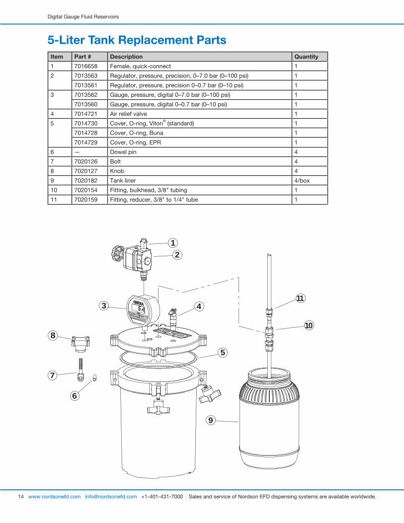
5-Liter Tank Replacement PartsItem Part # Description Quantity
1 7016658 Female, quick-connect 1
2 7013563 Regulator, pressure, precision, 0–7.0 bar (0–100 psi) 1
7013561 Regulator, pressure, precision 0–0.7 bar (0–10 psi) 1
3 7013562 Gauge, pressure, digital 0–7.0 bar (0–100 psi) 1
7013560 Gauge, pressure, digital 0–0.7 bar (0–10 psi) 1
4 7014721 Air relief valve 1
5 7014730 Cover, O-ring, Viton® (standard) 1
7014728 Cover, O-ring, Buna 1
7014729 Cover, O-ring, EPR 1
6 — Dowel pin 4
7 7020126 Bolt 4
8 7020127 Knob 4
9 7020182 Tank liner 4/box
10 7020154 Fitting, bulkhead, 3/8" tubing 1
11 7020159 Fitting, reducer, 3/8" to 1/4" tube 1
411
3
6
9
7
10
21
8
5

Digital Gauge Fluid Reservoirs
15www.nordsonefd.com [email protected] +1-401-431-7000 Sales and service of Nordson EFD dispensing systems are available worldwide.
TroubleshootingProblem Possible Cause Solution
Cannot set or maintain reservoir pressure
Cover clamps Make sure all cover clamps are secured not secured hand-tight.
Leaking feed tube bulkhead fitting
Make sure bulkhead fitting is assembled per instructions. If leak continues after proper installation, replace with new fitting.
Damaged cover O-ring seal Replace damaged O-ring seal.
Damaged/malfunctioning air relief valve
If air relief valve is not functioning properly, it MUST be replaced before returning the reservoir to service.
Kinked air supply line Make sure air supply line is straight and protected from other equipment.
Shutoff valve set to exhaust Make sure shutoff valve shuttle is set to “Pressurize”.
Cover seal surface dirty or damaged
Make sure cover sealing surface is free from debris or other contamination. The reservoir should be replaced if there is a cut or gouge in the sealing surface deep enough to prevent the tank from achieving its set pressure.
Damaged/malfunctioning air regulator
Replace with new air regulator.
Air supply is fluctuating Supply system regulator is required. EFD supplies the model #7002002 filter regulator. Set this regulator 0.7 bar (10 psi) below the lowest plant air fluctuation.
Digital gauge reading pressure without main line air input
Refer to page 8 for “Zeroing the Gauge” instructions.
Digital gauge is blank Gauge has automatic shutoff. Turn power back on.

For Nordson EFD sales and service in over 40 countries, contact Nordson EFD or go to www.nordsonefd.com.
Global 800-556-3484; +1-401-431-7000 [email protected]
Europe 00800 7001 7001 [email protected]
Asia China: +86 (21) 3866 9006; [email protected] India: +91 80 4021 3600; [email protected] Japan: +81 03 5762 2760; [email protected] Korea: +82-31-736-8321; [email protected] SEAsia: +65 6796 9522; [email protected]
The Wave Design is a trademark of Nordson Corporation. ©2021 Nordson Corporation 7026823 v010521


