Chapter 1 Digital Image Basics 1.1 What is a Digital Image? To understand what a digital image is, we have to first realize that what we see when we look at a “digital image” is actually a physical image reconstructed from a digital image. The digital image itself is really a data structure within the computer, containing a number or code for each pixel or picture element in the image. This code determines the color of that pixel. Each pixel can be thought of as a discrete sample of a continuous real image. It is helpful to think about the common ways that a digital image is created. Some of the main ways are via a digital camera, a page or slide scanner, a 3D rendering program, or a paint or drawing package. The simplest process to understand is the one used by the digital camera. Figure 1.1 diagrams how a digital image is made with a digital camera. The camera is aimed at a scene in the world, and light from the scene is focused onto the camera’s picture plane by the lens (Figure 1.1a). The camera’s picture plane contains photosensors arranged in a grid-like array, with one sensor for each pixel in the resulting image (Figure 1.1b). Each sensor emits a voltage proportional to the intensity of the light falling on it, and an analog to digital conversion circuit converts the voltage to a binary code or number suitable for storage in a cell of computer memory. This code is called the pixel’s value. The typical storage structure is a 2D array of pixel values, arranged so that the layout of pixel values in memory is organized into a regular grid with row and column numbers corresponding with the row and column numbers of the photosensor reading this pixel’s value (Figure 1.1c). Since each photosensor has a finite area, as indicated by the circles in Figure 1
Transcript
Chapter 1
Digital Image Basics
1.1 What is a Digital Image?
To understand what a digital image is, we have to first realize that what we seewhen we look at a “digital image” is actually a physical image reconstructedfrom a digital image. The digital image itself is really a data structure withinthe computer, containing a number or code for each pixel or picture elementin the image. This code determines the color of that pixel. Each pixel can bethought of as a discrete sample of a continuous real image.
It is helpful to think about the common ways that a digital image is created.Some of the main ways are via a digital camera, a page or slide scanner, a 3Drendering program, or a paint or drawing package. The simplest process tounderstand is the one used by the digital camera.
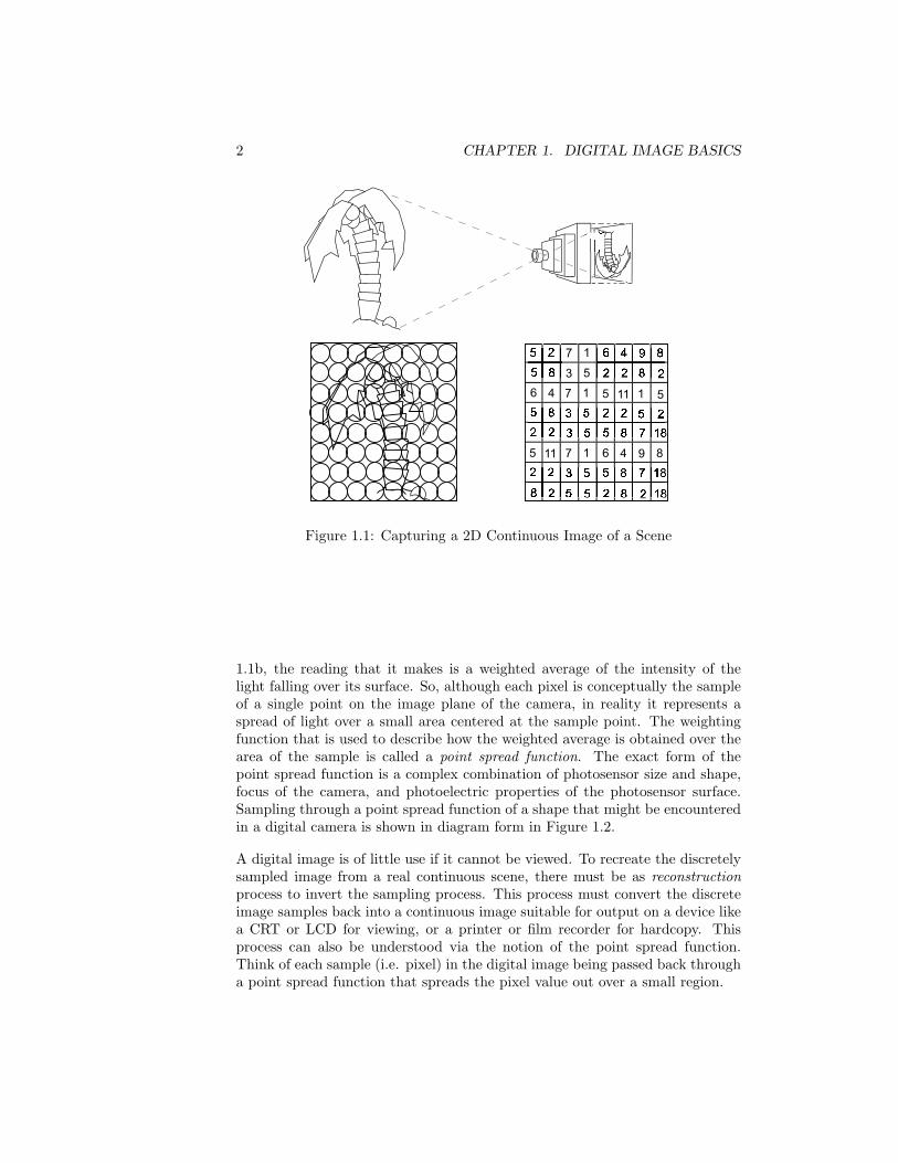
Figure 1.1 diagrams how a digital image is made with a digital camera. Thecamera is aimed at a scene in the world, and light from the scene is focusedonto the camera’s picture plane by the lens (Figure 1.1a). The camera’s pictureplane contains photosensors arranged in a grid-like array, with one sensor foreach pixel in the resulting image (Figure 1.1b). Each sensor emits a voltageproportional to the intensity of the light falling on it, and an analog to digitalconversion circuit converts the voltage to a binary code or number suitable forstorage in a cell of computer memory. This code is called the pixel’s value.The typical storage structure is a 2D array of pixel values, arranged so thatthe layout of pixel values in memory is organized into a regular grid with rowand column numbers corresponding with the row and column numbers of thephotosensor reading this pixel’s value (Figure 1.1c).
Since each photosensor has a finite area, as indicated by the circles in Figure
1
2 CHAPTER 1. DIGITAL IMAGE BASICS
Figure 1.1: Capturing a 2D Continuous Image of a Scene
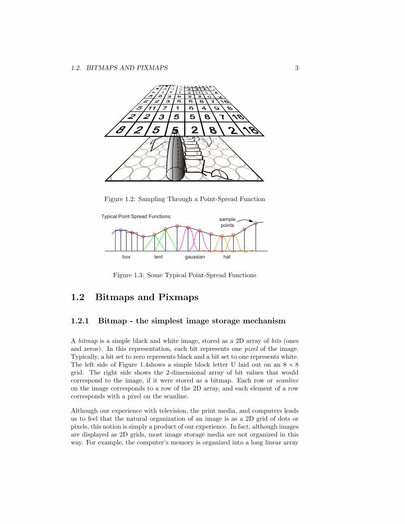
1.1b, the reading that it makes is a weighted average of the intensity of thelight falling over its surface. So, although each pixel is conceptually the sampleof a single point on the image plane of the camera, in reality it represents aspread of light over a small area centered at the sample point. The weightingfunction that is used to describe how the weighted average is obtained over thearea of the sample is called a point spread function. The exact form of thepoint spread function is a complex combination of photosensor size and shape,focus of the camera, and photoelectric properties of the photosensor surface.Sampling through a point spread function of a shape that might be encounteredin a digital camera is shown in diagram form in Figure 1.2.
A digital image is of little use if it cannot be viewed. To recreate the discretelysampled image from a real continuous scene, there must be as reconstructionprocess to invert the sampling process. This process must convert the discreteimage samples back into a continuous image suitable for output on a device likea CRT or LCD for viewing, or a printer or film recorder for hardcopy. Thisprocess can also be understood via the notion of the point spread function.Think of each sample (i.e. pixel) in the digital image being passed back througha point spread function that spreads the pixel value out over a small region.
1.2. BITMAPS AND PIXMAPS 3
Figure 1.2: Sampling Through a Point-Spread Function
box tent gaussian hat
Typical Point Spread Functions: sample points
Figure 1.3: Some Typical Point-Spread Functions
1.2 Bitmaps and Pixmaps
1.2.1 Bitmap - the simplest image storage mechanism
A bitmap is a simple black and white image, stored as a 2D array of bits (onesand zeros). In this representation, each bit represents one pixel of the image.Typically, a bit set to zero represents black and a bit set to one represents white.The left side of Figure 1.4shows a simple block letter U laid out on an 8 × 8grid. The right side shows the 2-dimensional array of bit values that wouldcorrespond to the image, if it were stored as a bitmap. Each row or scanlineon the image corresponds to a row of the 2D array, and each element of a rowcorresponds with a pixel on the scanline.
Although our experience with television, the print media, and computers leadsus to feel that the natural organization of an image is as a 2D grid of dots orpixels, this notion is simply a product of our experience. In fact, although imagesare displayed as 2D grids, most image storage media are not organized in thisway. For example, the computer’s memory is organized into a long linear array
Figure 1.4: Image of Black Block Letter U and Corresponding Bitmap
of addressable bytes (8 bit groups) of storage. Thus, somewhere in the memoryof a typical computer, the block letter U of Figure 1.4 might be represented asthe following string of contiguous bytes:
Since the memory is addressable only at the byte level, the color of each pixel(black or white) must be extracted from the byte holding the pixel’s value. And,since the memory is addressed as a linear array, rather than as a 2D array, acomputation must be made to determine which byte in the representation con-tains the pixel that we wish to examine, and which bit in that byte correspondswith the pixel.
The procedure print_bitmap() in Figure 1.5 will print the contents of the im-age stored in the array named bitmap. We assume that the image representedby bitmap contains exactly width * height pixels, organized into height scan-lines, each of length width. In other words, the number of pixels vertically alongthe image is height, and the number of pixels horizontally across the image iswidth. The print_bitmap() procedure assumes that each scanline in memoryis padded out to a multiple of 8 bits (pixels), so that it exactly fits into aninteger number of bytes. The variable w gives the width of a scanline in bytes.
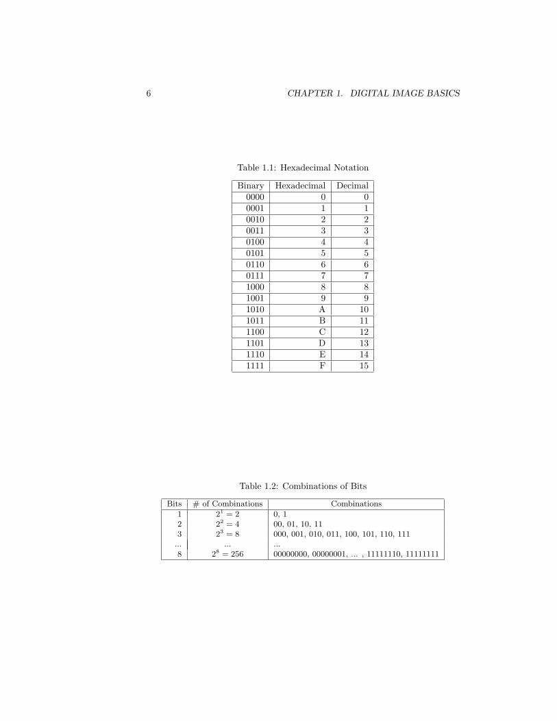
Another issue is that the representation of groups of pixels in terms of listsof ones and zeros is extremely difficult for humans to deal with cognitively.To convince yourself of this, try looking at a group of two or more bytes ofinformation, remembering what you see, and then writing down the numbersfrom memory. To make the handling of this binary encoded information moremanageable, it is convenient to think of each group of 4 bits as encoding ahexadecimal number. The hexadecimal numbers are the numbers written usinga base of 16, as opposed to the usual decimal numbers that use base 10, or thebinary numbers of the computer that use base 2. Since 16 is the 4th powerof 2, each hexadecimal digit can be represented exactly by a unique patternof 4 binary digits. These patterns are given in table Table 1.1, and becauseof their regular organization they can be easily memorized. With the device
1.2. BITMAPS AND PIXMAPS 5
void print_bitmap(unsigned char *bitmap, int width, int height){
int w = (width + 7) / 8; // number of bytes per scanline
int row; // scanline number (row)int col; // pixel number on scanline (column)int byte; // byte number within bitmap arrayint bit; // bit number within byteint value; // value of bit (0 or 1)
for(row = 0; row < height; row++){ // loop for each scanlinefor(col = 0; col < width; col++){ // loop for each pixel on linebyte = row * w + col / 8;bit = 7 - col % 8;value = bitmap[byte] >> bit & 1; // isolate bitprintf("%1d", value);
}printf("\n");
}}
Figure 1.5: Procedure to Print the Contents of a Bitmap
of hexadecimal notation, we can now display the internal representation of theblock letter U, by representing each 8-bit byte by two hexadecimal digits. Thisreduces the display to:
FF DB DB DB DB DB C3 FF
1.2.2 Pixmap - Representing Grey Levels or Color
If the pixels of an image can be arbitrary grey tones, rather than simply blackor white, we could allocate enough space in memory to store a real number,rather than a single bit, for each pixel. Then arbitrary levels of grey could berepresented as a 2D array of real numbers, say between 0 and 1, with pixel colorvarying smoothly from black at 0.0 through mid-grey at 0.5 to white at 1.0.However, this scheme would be very inefficient, since floating point numbers(the computer equivalent of real numbers) typically take 32 or more bits tostore. Thus image size would grow 32 times from that needed to store a simplebitmap. The pixmap is an efficient alternative to the idea of using a full floatingpoint number for each pixel. The main idea is that we can take advantage ofthe eye’s finite ability to discriminate levels of grey.
6 CHAPTER 1. DIGITAL IMAGE BASICS
Table 1.1: Hexadecimal Notation
Binary Hexadecimal Decimal0000 0 00001 1 10010 2 20011 3 30100 4 40101 5 50110 6 60111 7 71000 8 81001 9 91010 A 101011 B 111100 C 121101 D 131110 E 141111 F 15
It is a simple mathematical fact that in a group of n bits, the number of distinctcombinations of 1’s and 0’s is 2n. In other words, n bits of storage will allowus to represent and discriminate among exactly 2n different values or pieces ofinformation. This relationship is shown in tabular form in Table 1.2. If, in ourimage representation, we use 1 byte (8 bits) to represent each pixel, then wecan represent up to 256 different grey levels. This turns out to be enough to“fool” the eye of most people. If these 256 different grey levels are drawn asvertical lines across a computer screen, people will think that they are seeing asmoothly varying grey scale.
The structure of a pixmap, then, is a 2D array of pixel values, with each pixel’svalue stored as a group of 2 or more bits. To conform to byte boundaries, thenumber of bits used is typically 8, 16, 24 or 32 bits per pixel, although any size ispossible. If we think of the bits within a byte as representing a binary number,we can store grey levels between 0 and 255 in 8 bits. We can easily convert thepixel value in each byte to a grey level between 0.0 and 1.0 by dividing the pixelvalue by the maximum grey value of 255.
Assuming that we have a pixmap storing grey levels in eight bits per pixel, theprocedure print_greymap() in Figure 1.6 will print the contents of the imagestored in the array named greymap. We assume that the image representedby greymap contains exactly width * height pixels, organized into heightscanlines, each of length width.
void print_greymap(unsigned char *greymap, int width, int height){
int row; // scanline number (row)int col; // pixel number on scanline (column)int value; // value of pixel (0 to 255)
for(row = 0; row < height; row++){ // loop for each scanlinefor(col = 0; col < width; col++){ // loop for each pixel on linevalue = greymap[row * width + col]; // fetch pixel valueprintf("%5.3f ", value / 255.0);
}printf("\n");
}}
Figure 1.6: Procedure to Print the Contents of an 8 bit/pixel Greylevel Pixmap
8 CHAPTER 1. DIGITAL IMAGE BASICS
1.3 The RGB Color Space
If we want to store color images, we need a scheme of color representation thatwill allow us to represent color in a pattern of bits (just like we represented greylevels as patterns of bits). Fortunately, many such representations exist, andthe most common one used for image storage is the RGB or Red-Green-Bluesystem. This takes advantage of the fact that we can “fool” the human eye into“seeing” most of the colors that we can recognize perceptually by superimposing3 lights colored red, green and blue. The level or intensity of each of the threelights determines the color that we perceive.
Red
Green
Blue ColoredSpot
Figure 1.7: Additive Color Mixing for the Red-Green-Blue System
If we think of red, green, and blue levels as varying from 0 (off) to 1 (fullbrightness), then a color can be represented as a red, green, blue triple. Someexample color representations using this on/off scheme are shown in Figure 1.8.It is interesting and somewhat surprising that yellow is made by combining redand green!
Now, we can extend this idea by allowing a group of bits to represent one pixel.We can assign some of these bits to the red level, some to green, and someto blue, using a binary encoding scheme like we used to store grey level. For
1.3. THE RGB COLOR SPACE 9
example, if we have only 8 bits per pixel, we might use three for the red level,3 for green, and 2 for blue (since our eye discriminates blue much more weaklythan red or green). Figure 1.9 shows how a muted green color could be storedusing this kind of scheme. The value actually stored is hexadecimal 59, whichis then shown in binary broken into red, green and blue binary fields. Each ofthese binary numbers is divided by the maximum unsigned number possible inthe designated number of bits, and finally shown represented as a (RGB) tripleof color primary values, each on a scale of 0 – 1.
On a high end graphics computer, it is not unusual to allocate 24 bits per pixelfor color representation, allowing 8 bits for each of the red, green and bluecomponents. This is more than enough to allow for perceptually smooth colorgradations, and fits nicely into a computer whose memory is organized into 8-bitbytes. If you read specifications for computer displays or use graphics software,you will have noticed that many of these systems use red, green, and blue levelsbetween 0-255. These are obviously systems that use an 8-bit per color primaryrepresentation.
5916 =010 110 01R G B
= (2/7, 6/7, 1/3) = (0.286, 0.757, 0.333)
Figure 1.9: 8-Bit Encoding of a Muted Green
White(1,1,1)
Red(1,0,0)
Green(0,1,0)
Black(0,0,0)
Magenta(1,0,1)
Cyan(0,1,1)
Yellow(1,1,0)
Blue(0,0,1)
G
B
R
Figure 1.10: RGB Color Cube
Since the RGB system organizes color into three primaries, and allows us toscale each primary independently, we can think of all of the colors that arerepresented by the system as being organized in the shape of a cube, as shownin Figure 1.10. We call this the RGB color cube, or the RGB color space (whenwe add coordinate axes to measure R, G and B levels). Note that the cornersof the RGB color cube represent pure black and pure white, the three primariesred, green and blue, and the 3 secondary colors yellow, cyan and magenta. The
10 CHAPTER 1. DIGITAL IMAGE BASICS
diagonal from the black corner to the white corner represents all of the greylevels. Other locations within the cube correspond with all of the other colorsthat can be displayed.
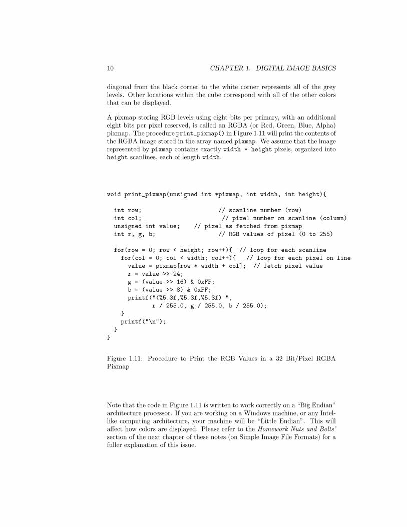
A pixmap storing RGB levels using eight bits per primary, with an additionaleight bits per pixel reserved, is called an RGBA (or Red, Green, Blue, Alpha)pixmap. The procedure print_pixmap() in Figure 1.11 will print the contents ofthe RGBA image stored in the array named pixmap. We assume that the imagerepresented by pixmap contains exactly width * height pixels, organized intoheight scanlines, each of length width.
void print_pixmap(unsigned int *pixmap, int width, int height){
int row; // scanline number (row)int col; // pixel number on scanline (column)unsigned int value; // pixel as fetched from pixmapint r, g, b; // RGB values of pixel (0 to 255)
for(row = 0; row < height; row++){ // loop for each scanlinefor(col = 0; col < width; col++){ // loop for each pixel on linevalue = pixmap[row * width + col]; // fetch pixel valuer = value >> 24;g = (value >> 16) & 0xFF;b = (value >> 8) & 0xFF;printf("(%5.3f,%5.3f,%5.3f) ",
r / 255.0, g / 255.0, b / 255.0);}printf("\n");
}}
Figure 1.11: Procedure to Print the RGB Values in a 32 Bit/Pixel RGBAPixmap
Note that the code in Figure 1.11 is written to work correctly on a “Big Endian”architecture processor. If you are working on a Windows machine, or any Intel-like computing architecture, your machine will be “Little Endian”. This willaffect how colors are displayed. Please refer to the Homework Nuts and Bolts’section of the next chapter of these notes (on Simple Image File Formats) for afuller explanation of this issue.
1.4. OTHER WAYS TO ORGANIZE RGBA PIXMAPS 11
1.4 Other Ways to Organize RGBA Pixmaps
The method of storing red, green, blue and alpha values by packing them intoa single unsigned int (which is a 32 bit structure) as shown in the exampleFigure 1.11, is only one way to organize the storage of RGBA pixels. Anotherway would be to define a pixel to be an array of four unsigned characters, ora struct whose elements are four unsigned characters. You can do this using atype definition in C. For example
typedef unsigned char RGBApixel[4];
defines the type RGBApixel to be an array of four unsigned char. If you createa variable RGBApixel pixel, then pixel[0] will store the red value, pixel[1]will store the green value, pixel[2] will store the blue value, and pixel[3] willstore the alpha value for the pixel.
which defines the type RGBApixel to be a struct with four elements, each anunsigned char. Using this definition, if you create a variable RGBApixel pixel,then pixel.r will store the red value, pixel.g will store the green value,pixel.b will store the blue value, and pixel.a will store the alpha value.
In addition, it is a bit cumbersome to have to compute the index row * width + colinto the pixmap array every time you want to reference an individual pixel at rowrow and column col. It would be much easier if we could use a two-dimensionalarray notation, so that we could index the pixmap array directly using row andcol as array indices. Unfortunately, it is not possible to do this directly in Cif the width of the array (i.e. the number of columns) is not known at compiletime. When dealing with digital images this it is usually the case that whenyou are writing your program you will not know the exact image dimensions.This will usually be determined at runtime. Fortunately we can get around thisproblem by being clever about how we allocate the data structure to store thepixmap.
The trick that we can use is that C actually implements an array using pointerarithmetic. The name of an array is a pointer to the first cell in the block of
12 CHAPTER 1. DIGITAL IMAGE BASICS
memory holding the array. Then, the use of an array index causes the index,times the number of bytes in a cell of the array, to be added to the addressof the first cell in the array. So, if we have an array int array[10];, then,remembering that an integer takes four bytes in memory, array[0] stands forthe address of the first cell in the array: array + 0 * 4, and array[2] standsfor the address of the third cell in the array: array + 2 * 4.
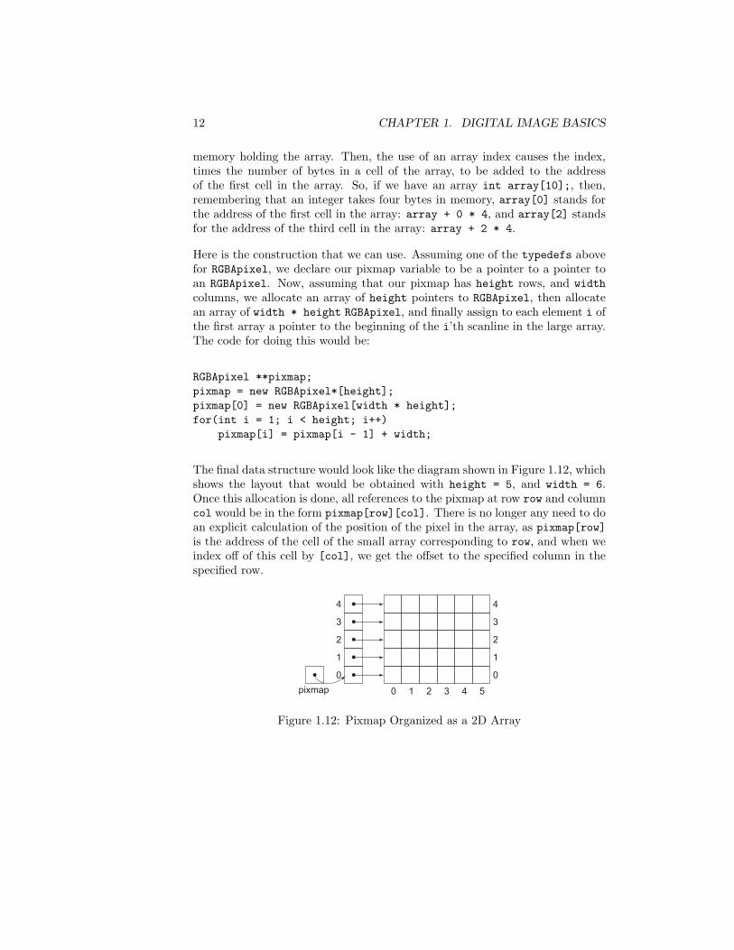
Here is the construction that we can use. Assuming one of the typedefs abovefor RGBApixel, we declare our pixmap variable to be a pointer to a pointer toan RGBApixel. Now, assuming that our pixmap has height rows, and widthcolumns, we allocate an array of height pointers to RGBApixel, then allocatean array of width * height RGBApixel, and finally assign to each element i ofthe first array a pointer to the beginning of the i’th scanline in the large array.The code for doing this would be:
RGBApixel **pixmap;pixmap = new RGBApixel*[height];pixmap[0] = new RGBApixel[width * height];for(int i = 1; i < height; i++)
pixmap[i] = pixmap[i - 1] + width;
The final data structure would look like the diagram shown in Figure 1.12, whichshows the layout that would be obtained with height = 5, and width = 6.Once this allocation is done, all references to the pixmap at row row and columncol would be in the form pixmap[row][col]. There is no longer any need to doan explicit calculation of the position of the pixel in the array, as pixmap[row]is the address of the cell of the small array corresponding to row, and when weindex off of this cell by [col], we get the offset to the specified column in thespecified row.