8226 p. 1/5 www.burkert.com Type 8644 Valve islands Digital inductive conductivity transmitter The conductivity transmitter Type 8226 com- bines a conductivity sensor and an electronic module with a display in an IP65 enclosure. The sensor component consists of a pair of magnetic coils in a PP, PVDF or PEEK housing. The cell constant is an average value over the whole measuring range. It can be re-adjusted depending on application. The integrated temperature probe for auto- matic compensation is a standard feature in the conductivity sensor housing. The transducer component converts the meas- ured signal and displays the actual value. The conductivity transmitter can be installed into pipe by using INSERTION fitting Type S020 available in stainless steel, brass or plastics. Type S020 INSERTION fitting Type 6642 Solenoid valve Type 2731 Diaphragm valve for continuous control Type 2030 On/Off Diaphragm valve • Optimal solution for conductivity measurements in difficult fluids (polluted, dirty,...) • PEEK/PPA version for CIP applications • Large range of process connections with various fittings • Multi language, menu-guided operation PLC Type 8226 can be combined with... General data Compatibility with fittings S020 (see corresponding data sheet) Materials Housing, cover, lid, nut Front panel foil / Screws Cable plug / gland Wetted parts materials Fitting Sensor holder / Seal PC glass reinforced fibre (if PVDF sensor) PPA glass reinforced fibre (if PP, PEEK sensor) Polyester / Stainless steel PA Brass, stainless steel 1.4404/316L, PVC, PP or PVDF PP, PVDF or PEEK / FKM or EPDM Display 15 x 60 mm, 8-digit LCD, alphanumeric, 15 segments, 9 mm high Electrical connections Cable plug acc. to EN 175301-803 or cable glands M20 x 1.5 Connection cable shielded cable with 1.5 mm 2 max. cross-section Complete device data (fitting + Electronics) Pipe diameter DN15 to DN200 Conductivity measurement Measurement type Measuring range Accuracy inductive conductivity measurement 100 S/cm...2 S/cm (cond.) or 0.5...10 k.cm (resis.) ± 2% of reading Temperature measurement Measurement type Accuracy Numeric measurement ±0.5°C (0.9°F) from 0...110°C (32 to 230°F) and ±1°C (1.8°F) from -15... 0°C (5 to 32°F) and 110... 120°C (230 to 248°F) Temperature compensation automatic (with standardized integrated temperature sensor) - reference temperature 25°C (77°F) Medium temperature max. with fitting in PVC: 5 to 50°C (41 to 122°F), - PP: 5 to 80°C (41 to 176°F) PVDF: -15 to 100°C (5 to 212°F) - stainless steel, brass: -15 to 120°C (5 to 248°F) Medium pressure max. PN6 (see pressure/temperature chart)
Transcript
8226
p. 1/5www.burkert.com
Type 8644
Valve islands
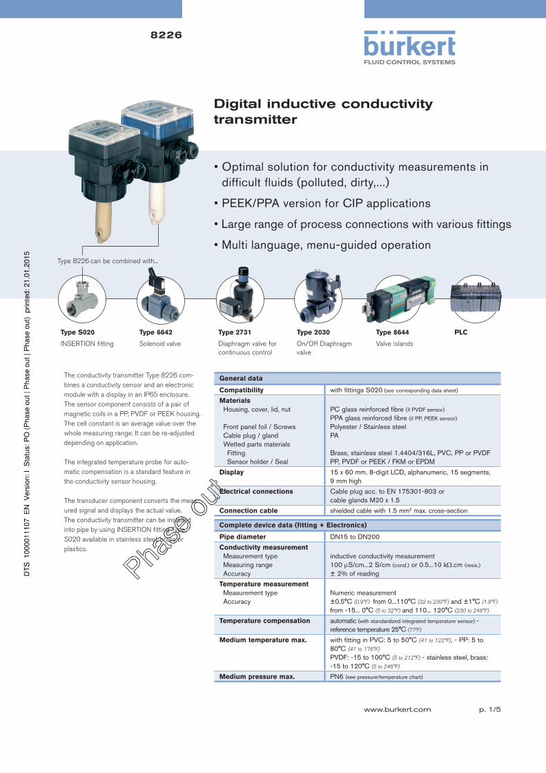
Digital inductive conductivity transmitter
The conductivity transmitter Type 8226 com-
bines a conductivity sensor and an electronic
module with a display in an IP65 enclosure.
The sensor component consists of a pair of
magnetic coils in a PP, PVDF or PEEK housing.
The cell constant is an average value over the
whole measuring range. It can be re-adjusted
depending on application.
The integrated temperature probe for auto-
matic compensation is a standard feature in
the conductivity sensor housing.
The transducer component converts the meas-
ured signal and displays the actual value.
The conductivity transmitter can be installed
into pipe by using INSERTION fitting Type
S020 available in stainless steel, brass or
plastics.
Type S020
INSERTION fitting
Type 6642
Solenoid valve
Type 2731
Diaphragm valve for
continuous control
Type 2030
On/Off Diaphragm
valve
• Optimal solution for conductivity measurements in difficult fluids (polluted, dirty,...)
• PEEK/PPA version for CIP applications
• Large range of process connections with various fittings
• Multi language, menu-guided operation
PLC
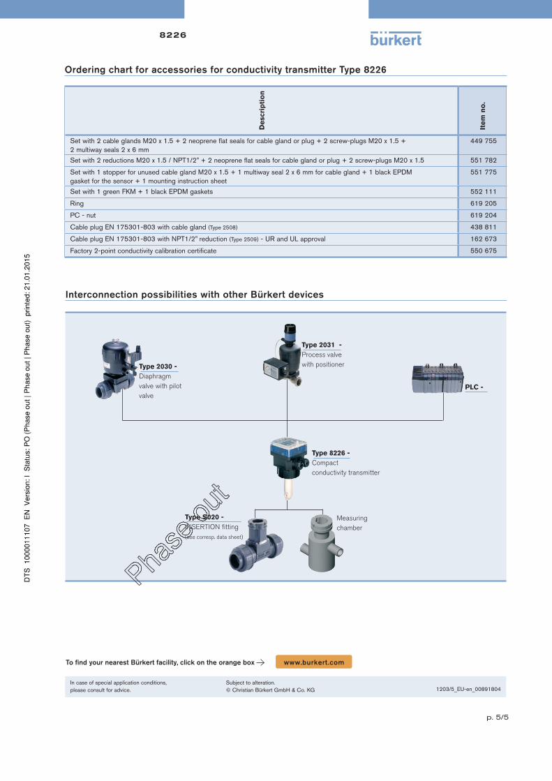
Type 8226 can be combined with...
General data
Compatibility with fittings S020 (see corresponding data sheet)
Materials
Housing, cover, lid, nut
Front panel foil / ScrewsCable plug / glandWetted parts materials Fitting
Sensor holder / Seal
PC glass reinforced fibre (if PVDF sensor)
PPA glass reinforced fibre (if PP, PEEK sensor)
Polyester / Stainless steelPA
Brass, stainless steel 1.4404/316L, PVC, PP or PVDFPP, PVDF or PEEK / FKM or EPDM
Display 15 x 60 mm, 8-digit LCD, alphanumeric, 15 segments, 9 mm high
Electrical connections Cable plug acc. to EN 175301-803 or cable glands M20 x 1.5
Connection cable shielded cable with 1.5 mm2 max. cross-section
Complete device data (fitting + Electronics)
Pipe diameter DN15 to DN200
Conductivity measurement
Measurement typeMeasuring rangeAccuracy
inductive conductivity measurement100 S/cm...2 S/cm (cond.) or 0.5...10 k.cm (resis.)
± 2% of reading
Temperature measurement
Measurement typeAccuracy
Numeric measurement±0.5°C (0.9°F) from 0...110°C (32 to 230°F) and ±1°C (1.8°F) from -15... 0°C (5 to 32°F) and 110... 120°C (230 to 248°F)
Temperature compensation automatic (with standardized integrated temperature sensor) - reference temperature 25°C (77°F)
Medium temperature max. with fitting in PVC: 5 to 50°C (41 to 122°F), - PP: 5 to 80°C (41 to 176°F)
PVDF: -15 to 100°C (5 to 212°F) - stainless steel, brass: -15 to 120°C (5 to 248°F)
Medium pressure max. PN6 (see pressure/temperature chart)
8226
p. 2/5
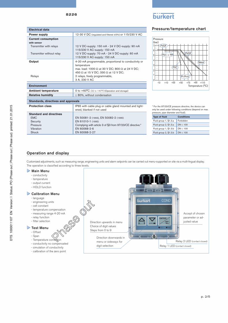
* For the 97/23/CE pressure directive, the device can only be used under following conditions (depend on max. pressure, pipe diameter and fluid).
Type of fluid Conditions
Fluid group 1, §1.3.a Forbidden
Fluid group 2, §1.3.a DN 100
Fluid group 1, §1.3.b DN 100
Fluid group 2, §1.3.b DN 100
Electrical data
Power supply 12-30 V DC (regulated and filtered ±5%) or 115/230 V AC
Current consumption
with sensor
Transmitter with relays
Transmitter without relay
12 V DC-supply: 150 mA - 24 V DC-supply: 90 mA115/230 V AC-supply: 150 mA12 V DC-supply: 70 mA - 24 V DC-supply: 60 mA115/230 V AC-supply: 150 mA
Output
Relays
4-20 mA programmable, proportional to conductivity or temperaturemax. load: 1000 at 30 V DC; 800 at 24 V DC;450 at 15 V DC; 330 at 12 V DC;2 relays, freely programmable,3 A, 230 V AC
Environment
Ambient temperature 0 to +60°C (32 to 140°F) (Operation and storage)
Relative humidity 80%, without condensation
Standards, directives and approvals
Protection class IP65 with cable plug or cable gland mounted and tight-ened, blanked if not used
Standard and directives
EMCSecurityPressure VibrationShock
EN 50081-2 (1993), EN 50082-2 (1995)
EN 61010-1 (1995)
Complying with article 3 of §3 from 97/23/CE directive.*EN 60068-2-6EN 60068-2-27
Pressure/temperature chart
Pressure(bar)
Temperature (°C)
Operation and display
Customized adjustments, such as measuring range, engineering units and alarm setpoints can be carried out menu-supported on site via a multi-lingual display.
The operation is classified according to three levels.
Main Menu
- conductivity
- temperature
- output current
- HOLD function
Calibration Menu
- language
- engineering units
- cell constant
- temperature compensation
- measuring range 4-20 mA
- relay function
- filter selection
Test Menu
- Offset
- Span
- Temperature correction
- conductivity no compensated
- simulation of conductivity
- calibration of the zero point
Direction upwards in menu
Choice of digit values
Steps from 0 to 9
Direction downwards in
menu or sideways for
digit selection
Relay 2 LED (contact closed)
Relay 1 LED (contact closed)
Accept of chosen
parameter or ad-
justed value
8226
p. 3/5
Principle of operation
The conductivity is defined as the ability of a solution to conduct electrical current. The load carriers are ions (E.G. dissolved salt or acids). In order to measure
conductivity, an AC voltage source is connected to the primary magnetic coil. The magnetic field induced generates a current in the secondary mag-
netic coil. The intensity of this induced current is a direct function of the conductivity of the solution.
A 4-.20 mA standard signal is available as output signal, proportional to the conductivity or the temperature of the fluid. The transmitter is available, in
option, with 2 relays.
The transmitter without relay or with 2 additional relays (limits values freely adjustable) functions in a three wire circuit and requires a power supply of 12-
30 V DC. The device is available with an integrated power supply of 115/230 V AC.
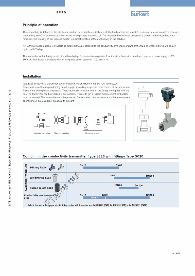
Horizontal mounting Vertical mounting Mounting in tank
with mixer
without mixer
Installation
The 8226 conductivity transmitter can be installed into any Bürkert INSERTION fitting (S020).
Select and install the required fitting onto the pipe, according to specific requirements of the sensor and
fitting material (temperature and pressure). Then, cautiously install the unit on the fitting, and tighten with the
nut. The transmitter can be installed in any position. In order to get a reliable measurement, air bubbles
must be avoided. The transmitter must be protected from constant heat radiation and other environmen-
tal influences, such as direct exposure to sunlight.
Combining the conductivity transmitter Type 8226 with fittings Type S020
Availab
le f
itti
ng
DN
T-fitting S020
Welding tab S020
Fusion spigot S020
Conductivity measurement
8226
Note A: Use only with analyse plastic fitting version with true union acc. to DIN 8063 (PVC), to DIN 16962 (PP) or to ISO 10931 (PVDF).
DN200
DN65DN15
DN50
DN100DN65
DN200DN15Note A
DN32
8226
p. 4/5
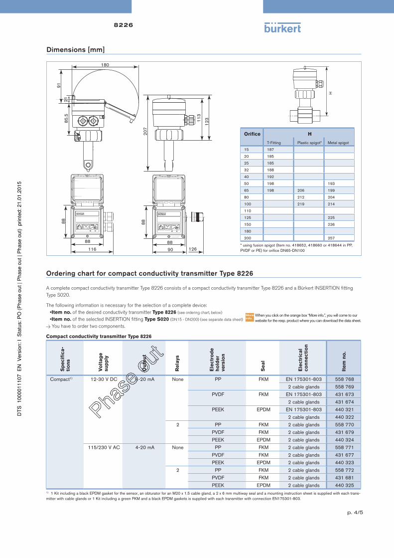
Dimensions [mm]
* using fusion spigot (Item no. 418652, 418660 or 418644 in PP, PVDF or PE) for orifice DN65-DN100
Orifice H
T-Fitting Plastic spigot* Metal spigot
15 187
20 185
25 185
32 188
40 192
50 198 193
65 198 206 199
80 212 204
100 219 214
110
125 225
150 236
180
200 257
Ordering chart for compact conductivity transmitter Type 8226
A complete compact conductivity transmitter Type 8226 consists of a compact conductivity transmitter Type 8226 and a Bürkert INSERTION fitting
Type S020.
The following information is necessary for the selection of a complete device:
•Item no. of the desired conductivity transmitter Type 8226 (see ordering chart, below)
•Item no. of the selected INSERTION fitting Type S020 (DN15 - DN200) (see separate data sheet)
You have to order two components.
Compact conductivity transmitter Type 8226
Sp
ecif
ica
-
tio
ns
Vo
lta
ge
su
pp
ly
Ou
tpu
t
Re
lays
Ele
ctr
od
e
ho
lde
r
ve
rsio
n
Se
al
Ele
ctr
ica
l
co
nn
ecti
on
Ite
m n
o.
Compact1) 12-30 V DC 4-20 mA None PP FKM EN 175301-803 558 768
2 cable glands 558 769
PVDF FKM EN 175301-803 431 673
2 cable glands 431 674
PEEK EPDM EN 175301-803 440 321
2 cable glands 440 322
2 PP FKM 2 cable glands 558 770
PVDF FKM 2 cable glands 431 679
PEEK EPDM 2 cable glands 440 324
115/230 V AC 4-20 mA None PP FKM 2 cable glands 558 771
PVDF FKM 2 cable glands 431 677
PEEK EPDM 2 cable glands 440 323
2 PP FKM 2 cable glands 558 772
PVDF FKM 2 cable glands 431 681
PEEK EPDM 2 cable glands 440 3251) 1 Kit including a black EPDM gasket for the sensor, an obturator for an M20 x 1.5 cable gland, a 2 x 6 mm multiway seal and a mounting instruction sheet is supplied with each trans-mitter with cable glands or 1 Kit including a green FKM and a black EPDM gaskets is supplied with each transmitter with connection EN175301-803.
When you click on the orange box “More info.”, you will come to our website for the resp. product where you can download the data sheet.
Ordering chart for accessories for conductivity transmitter Type 8226
De
scri
pti
on
Ite
m n
o.
Set with 2 cable glands M20 x 1.5 + 2 neoprene flat seals for cable gland or plug + 2 screw-plugs M20 x 1.5 + 2 multiway seals 2 x 6 mm
449 755
Set with 2 reductions M20 x 1.5 / NPT1/2” + 2 neoprene flat seals for cable gland or plug + 2 screw-plugs M20 x 1.5 551 782
Set with 1 stopper for unused cable gland M20 x 1.5 + 1 multiway seal 2 x 6 mm for cable gland + 1 black EPDM gasket for the sensor + 1 mounting instruction sheet
551 775
Set with 1 green FKM + 1 black EPDM gaskets 552 111
Ring 619 205
PC - nut 619 204
Cable plug EN 175301-803 with cable gland (Type 2508) 438 811
Cable plug EN 175301-803 with NPT1/2” reduction (Type 2509) - UR and UL approval 162 673


![Digital Conductivity Transmitter Type 8225 - iProcesSmart · Digital Conductivity Transmitter Type 8225 Dimensions [mm (inch)] Sensor Short Distance Conductivity-Sensor Type 8200](https://static.documents.pub/doc/80x56/5c71f2f909d3f285208b52c9/digital-conductivity-transmitter-type-8225-digital-conductivity-transmitter.jpg)


