Digital I/Os Plug-in Module Módulo Plug-in de Expansión de I/Os Digitales Módulo Plug-in de Expansão de I/Os Digitais CFW500 Installation, Configuration and Operation Guide Guía de Instalación, Configuración y Operación Guia de Instalação, Configuração e Operação Motors | Automation | Energy | Transmission & Distribution | Coatings
Transcript
Digital I/Os Plug-in Module
Módulo Plug-in de Expansión de I/Os Digitales
Módulo Plug-in de Expansão de I/Os Digitais
CFW500
Installation, Configuration and Operation Guide Guía de Instalación, Configuración y Operación Guia de Instalação, Configuração e Operação
Motors | Automation | Energy | Transmission & Distribution | Coatings
Summary / Índice
En
glis
hE
spañ
ol
Po
rtug
uês
SUMMARY
1 SAFETY INFORMATION ...............................51.1 SAFETY WARNINGS ...................................51.2 PRELIMINARY RECOMMENDATIONS .......5
2 GENERAL INFORMATION ...........................5
ANEXO A – FIGURAS .....................................20
Digital I/Os Plug-in Module
En
glis
h
CFW500 | 5
1 SAFETY INFORMATION
1.1 SAFETY WARNINGS
NOTE! Only use the p lug- in expansion
module for digital inputs and outputs (CFW500-IOD) on WEG inverters of the CFW500 line.
We recommend reading the CFW500 user’s manual before install ing or operating this accessory.
Th is gu ide conta ins impor tant i n f o r m a t i o n f o r t h e c o r r e c t understanding and proper operation of this module.
1.2 PRELIMINARY RECOMMENDATIONS
ATTENTION! Always d isconnect the genera l
power supply before connecting or disconnecting the accessories of the frequency inverter CFW500.
Wait for at least 10 minutes to guarantee complete de-energization of the inverter.
2 GENERAL INFORMATION This guide provides instructions for the installation, configuration and operation of the plug-in expansion module of digital inputs and outputs (CFW500-IOD).
Digital I/Os Plug-in Module
En
glish
6 | CFW500
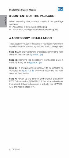
3 CONTENTS OF THE PACKAGE
When receiving the product, check if this package contains:
Accessory in anti-static packaging. Installation, configuration and operation guide.
4 ACCESSORY INSTALLATION
The accessory is easily installed or replaced. For correct installation of the accessory execute the following steps:
Step 1: With the inverter de-energized, remove the front cover of the Inverter (figure A.1 (a)).
Step 2: Remove the accessory (connected plug-in module) if any, as in figure A.1 (a).
Step 3: Fit and press the accessory to be installed as indicated in figure A.1 (b) and then assemble the front cover of the inverter.
Step 4: Power up the inverter and check if parameter P0027 shows value 2 (P0027=2). If this information is not true, check if the module used is actually the CFW500-IOD and repeat steps 1-4.
Digital I/Os Plug-in Module
En
glis
h
CFW500 | 7
5 SETTINGS
The control connections (analogical input / output, digital inputs / outputs and RS485 interface) must be performed as shown in figure 1.
Connector Description
Sup
erio
r Te
rmin
al
1 DI1 Digital input 1
3 DI2 Digital input 2
5 DI3 Digital input 3
7 DI4 Digital input 4
9 +24 V +24 Vdc Power suply
11 DO1-RL-NODigital output 1
(NO contact of relay 1)
13 DO1-RL-CDigital output 1
(common point of relay 1)
15 DO1-RL-NCDigital output 1
(NC contact of relay 1)
17 DI5 Digital input 5
19 DI6 Digital input 6
21 DI7 Digital input 7
23 DI8 Digital input 8
Infe
rior
Term
inal
2 AO1 Analogical output 1
4 GND Reference 0 V
6 AI1 Analogical input 1
8 +10 VReference +10 Vdc for
potentiometer
10 DO2-TR Digital output 2 (Transistor)
12 RS485 - A RS485 (Terminal A)
14 RS485 - B RS485 (Terminal B)
16 GND Reference 0 V
18 GND Reference 0 V
20 DO3-TR Digital output 3 (Transistor)
22 DO4-TR Digital output 4 (Transistor)
24 DO5-TR Digital output 5 (Transistor)
Figure 1: Signals of control connector
Digital I/Os Plug-in Module
En
glish
8 | CFW500
DI1
DI2
DI3
DI7
DI4 GND
DI8
DO
1-R
L-N
OR
S48
5 - A
+24
V
DI5
DI6
DO
1-R
L-C
RS
485
- BD
O1-
RL-
NC
GN
D
GN
D
GN
D
AO
1
AI1
+10
V
DO
2-TR
DO
4-TR
DO
3-TR
DO
5-TR
≥5
kΩ
R RR Rrpm
+24 V
Figure 2: Signals of the control connector
The location of the DIP-switches for selecting the type of analog input and output signal and termination of the RS485 line can be better visualized in figure A.2. To use the analog inputs and/ or outputs with signal in current, switch S1 and related parameters must be set as indicated in table 1. For further details about the control connections see chapter 3 - Installation and Connection of the CFW500 user's manual.
Digital I/Os Plug-in Module
En
glis
h
CFW500 | 9
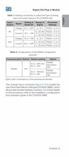
Table 1: Settings of switches to select the type of analog input and output signal of the CFW500-IOD
Input/Output Signal Setting of
Switch S1Range of
SignalParameter Settings
AI1
Voltage S1.1 = OFF 0...10 V P0233 = 0 or 2
Current S1.1 = ON 0...20 mA P0233 = 0 or 2
4...20 mA P0233 = 1 or 3
AO1
Voltage S1.2 = ON 0...10 V P0253 = 0 or 3
Current S1.2 = OFF0...20 mA P0253 = 1 or 4
4...20 mA P0253 = 2 or 5
Table 2: Configurations of the RS485 configuration switches
Communication Switch Switch setting Option
RS485 S1(*)
S1.3 = OFF and S1.4 = OFF
RS485 termination OFF
S1.3 = ON and S1.4 = ON
RS485 termination ON
(*) No other combinations of the switches are allowed.
This module has a connector (figure A.2) to enable the use of the Flash Memory Module (CFW500-MMF), which allows data transfer between inverters. For further details on this accessory, refer to the installation, configuration and operation guide of the CFW500-MMF.
Módulo Plug-in de Expansión de I/Os Digitales
10 | CFW500
Esp
año
l
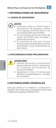
1 INFORMACIONES DE SEGURIDAD
1.1 AVISOS DE SEGURIDAD
¡NOTA! Solamente uti l izar el módulo plug-in
de expansión de entradas y sal idas (I/Os) digitales (CFW500-IOD) en los convertidores WEG línea CFW500.
Se recomienda la lectura del manual del usuario del CFW500 antes de instalar u operar este accesorio.
El contenido de esta gu ía fornece informaciones importantes para el correcto entendimiento y buen funcionamento de este módulo.
1.2 RECOMENDACIONES PRELIMINARES
¡ATENCIÓN! Siempre desconecte la alimentación
general antes de conectar o desconectar los accesor ios de l conver t idor de frecuencia CFW500.
Aguarde por lo menos 10 minutos para garantizar la desenergización completa del convertidor.
2 INFORMACIONES GENERALES Esta guía orienta en la instalación, configuración y operación del módulo plug-in de expansión de entradas y salidas (I/Os) digitales (CFW500-IOD).
Módulo Plug-in de Expansión de I/Os Digitales
CFW500 | 11
Esp
año
l
3 CONTENIDO DEL EMBALAJE
Al recibir el producto, verifique si el embalaje contiene: Accesorio en embalaje antiestático. Guía de instalación, configuración y operación.
4 INSTALACIÓN DEL ACCESORIO
El accesorio es fácilmente instalado o sustituido. Para la correcta instalación del accesorio, ejecute los pasos a seguir:
Paso 1: Con el convertidor desenergizado, retire la tapa frontal del mismo (figura A.1 (a)).
Paso 2: Retire, si existe, el accesorio (módulo plug-in conectado) conforme la figura A.1 (a).
Paso 3: Encaje y presione el accesorio a ser instalado conforme indicado en la figura A.1 (b) y después conecte la tapa frontal del convertidor.
Paso 4: Energice el convertidor y verif ique si el parámetro P0027 indica el valor 2 (P0027=2). En caso de que esa información no sea verdadera, verifique si el módulo utilizado realmente es el CFW500-IOD y repita los pasos 1-4.
Módulo Plug-in de Expansión de I/Os Digitales
12 | CFW500
Esp
año
l
5 CONFIGURACIONES
Las conexiones de control (entrada/salida analógica, entradas/salidas digitales e interfaz RS485) deben ser hechas en el conector conforme figura 1.
Conector Descripción
Bor
ne S
uper
ior
1 DI1 Entrada Digital 1
3 DI2 Entrada Digital 2
5 DI3 Entrada Digital 3
7 DI4 Entrada Digital 4
9 +24 V Fuente +24 Vcc
11 DO1-RL-NOSalida digital 1
(contacto NA del relé 1)
13 DO1-RL-CSalida digital 1
(punto común del relé 1)
15 DO1-RL-NCSalida digital 1
(contacto NF del relé 1)
17 DI5 Entrada Digital 5
19 DI6 Entrada Digital 6
21 DI7 Entrada Digital 7
23 DI8 Entrada Digital 8
Bor
ne In
ferio
r
2 AO1 Salida analógica 1
4 GND Referencia 0 V
6 AI1 Entrada Analógica 1
8 +10 VReferencia +10 Vcc para
potenciómetro
10 DO2-TR Salida digital 2 (Transistor)
12 RS485 - A RS485 (Terminal A)
14 RS485 - B RS485 (Terminal B)
16 GND Referencia 0 V
18 GND Referencia 0 V
20 DO3-TR Salida digital 3 (Transistor)
22 DO4-TR Salida digital 4 (Transistor)
24 DO5-TR Salida digital 5 (Transistor)
Figura 1: Señales del conector de control
Módulo Plug-in de Expansión de I/Os Digitales
CFW500 | 13
Esp
año
l
DI1
DI2
DI3
DI7
DI4 GND
DI8
DO
1-R
L-N
OR
S48
5 - A
+24
V
DI5
DI6
DO
1-R
L-C
RS
485
- BD
O1-
RL-
NC
GN
D
GN
D
GN
D
AO
1
AI1
+10
V
DO
2-TR
DO
4-TR
DO
3-TR
DO
5-TR
≥5
kΩ
R RR Rrpm
+24 V
Figura 2: Señales del conector de control
La localización de las DIP-switches para selección del tipo de señal de la entrada y salida analógica y de la terminación de la red RS485 pueden ser mejor visualizadas en la figura A.2. Para utilizar las entradas y/u salidas analógicas con señal en corriente, se debe ajustar la llave S1 y los parámetros relacionados conforme tabla 1. Para más detal les sobre las conexiones de control consulte el capítulo 3 - Instalación y Conexion del manual del usuario del CFW500.
Módulo Plug-in de Expansión de I/Os Digitales
14 | CFW500
Esp
año
l
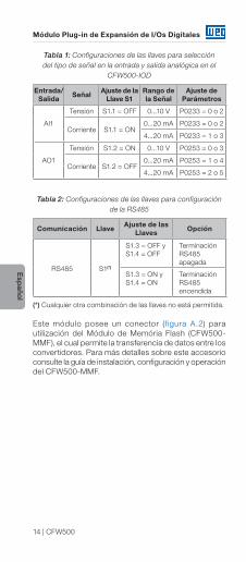
Tabla 1: Configuraciones de las llaves para selección del tipo de señal en la entrada y salida analógica en el
CFW500-IOD
Entrada/Salida Señal Ajuste de la
Llave S1Rango de la Señal
Ajuste de Parámetros
AI1
Tensión S1.1 = OFF 0...10 V P0233 = 0 o 2
Corriente S1.1 = ON 0...20 mA P0233 = 0 o 2
4...20 mA P0233 = 1 o 3
AO1
Tensión S1.2 = ON 0...10 V P0253 = 0 o 3
Corriente S1.2 = OFF0...20 mA P0253 = 1 o 4
4...20 mA P0253 = 2 o 5
Tabla 2: Configuraciones de las llaves para configuración de la RS485
Comunicación Llave Ajuste de las Llaves Opción
RS485 S1(*)
S1.3 = OFF y S1.4 = OFF
Terminación RS485 apagada
S1.3 = ON y S1.4 = ON
Terminación RS485 encendida
(*) Cualquier otra combinación de las llaves no está permitida.
Este módulo posee un conector (f igura A.2) para utilización del Módulo de Memória Flash (CFW500-MMF), el cual permite la transferencia de datos entre los convertidores. Para más detalles sobre este accesorio consulte la guía de instalación, configuración y operación del CFW500-MMF.
Módulo Plug-in de Expansão de I/Os Digitais
CFW500 | 15
Po
rtug
uês
1 INFORMAÇÕES DE SEGURANÇA
1.1 AVISOS DE SEGURANÇA
NOTA! Somente utilizar o módulo plug-in de
expansão de entradas e saídas (I/Os) digitais (CFW500-IOD) nos inversores WEG linha CFW500.
Recomenda-se a leitura do manual do usuário do CFW500 antes de instalar ou operar esse acessório.
O c o n te ú d o d e s te g u i a f o r n e c e informações importantes para o correto entendimento e bom funcionamento deste módulo.
1.2 RECOMENDAÇÕES PRELIMINARES
ATENÇÃO! Sempre desconecte a alimentação geral
antes de conectar ou desconectar os acessórios do inversor de frequência CFW500.
Aguarde pelo menos 10 minutos para garantir a desenergização completa do inversor.
2 INFORMAÇÕES GERAIS Este guia orienta na instalação, configuração e operação do módulo plug-in de expansão de entradas e saídas (I/Os) digitais (CFW500-IOD).
Módulo Plug-in de Expansão de I/Os Digitais
16 | CFW500
Po
rtuguês
3 CONTEÚDO DA EMBALAGEM
Ao receber o produto, verificar se a embalagem contém: Acessório em embalagem anti-estática. Guia de instalação, configuração e operação.
4 INSTALAÇÃO DO ACESSÓRIO
O acessório é facilmente instalado ou substituído. Para a correta instalação do acessório execute os passos a seguir:
Passo 1: Com o inversor desenergizado, retire a tampa frontal do Inversor conforme figura A.1 (a).
Passo 2: Retire, se houver, o acessório (módulo plug-in conectado) conforme a figura A.1 (a).
Passo 3: Encaixe e pressione o acessório a ser instalado conforme indicado na figura A.1 (b) e após conecte a tampa frontal do inversor.
Passo 4: Energize o inversor e verifique se o parâmetro P0027 indica o valor 2 (P0027=2). Caso essa informação não for verdadeira, verifique se o módulo utilizado realmente é o CFW500-IOD e repita os passos 1-4.
Módulo Plug-in de Expansão de I/Os Digitais
CFW500 | 17
Po
rtug
uês
5 CONFIGURAÇÕES
As conexões de controle (entrada/saída analógica, entradas/saídas digitais e interface RS485) devem ser feitas no conector conforme figura 1.
Conector Descrição
Bor
ne S
uper
ior
1 DI1 Entrada Digital 1
3 DI2 Entrada Digital 2
5 DI3 Entrada Digital 3
7 DI4 Entrada Digital 4
9 +24 V Fonte +24 Vcc
11 DO1-RL-NOSaída Digital 1
(Contato NA do Relé 1)
13 DO1-RL-CSaída Digital 1
(Ponto comum do Relé 1)
15 DO1-RL-NCSaída Digital 1
(Contato NF do Relé 1)
17 DI5 Entrada Digital 5
19 DI6 Entrada Digital 6
21 DI7 Entrada Digital 7
23 DI8 Entrada Digital 8
Bor
ne In
ferio
r
2 AO1 Saída Analógica 1
4 GND Referência 0 V
6 AI1 Entrada Analógica 1
8 +10 VReferência +10 Vcc para
Potenciômetro
10 DO2-TR Saída Digital 2 (Transistor)
12 RS485 - A RS485 (Terminal A)
14 RS485 - B RS485 (Terminal B)
16 GND Referência 0 V
18 GND Referência 0 V
20 DO3-TR Saída Digital 3 (Transistor)
22 DO4-TR Saída Digital 4 (Transistor)
DO5-TR Saída Digital 5 (Transistor)
Figura 1: Sinais do conector de controle
Módulo Plug-in de Expansão de I/Os Digitais
18 | CFW500
Po
rtuguês
DI1
DI2
DI3
DI7
DI4 GND
DI8
DO
1-R
L-N
OR
S48
5 - A
+24
V
DI5
DI6
DO
1-R
L-C
RS
485
- BD
O1-
RL-
NC
GN
D
GN
D
GN
D
AO
1
AI1
+10
V
DO
2-TR
DO
4-TR
DO
3-TR
DO
5-TR
≥5
kΩ
R RR Rrpm
+24 V
Figura 2: Sinais do conector de controle
A localização das DIP-switches para seleção do tipo de sinal da entrada e saída analógica e da terminação da rede RS485 podem ser melhor visualizadas na figura A.2. Para utilizar as entradas e/ou saídas analógicas com sinal em corrente deve-se ajustar a chave S1 e os parâmetros relacionados conforme tabela 1. Para mais detalhes sobre as conexões de controle consulte o capítulo 3 do manual do usuário do CFW500.
Módulo Plug-in de Expansão de I/Os Digitais
CFW500 | 19
Po
rtug
uês
Tabela 1: Configurações das chaves para seleção do tipo de sinal na entrada e saída analógica no CFW500-IOD
Entrada/Saída Sinal Ajuste da
Chave S1Faixa do
SinalAjuste de
Parâmetros
AI1
Tensão S1.1 = OFF 0...10 V P0233 = 0 ou 2
Corrente S1.1 = ON 0...20 mA P0233 = 0 ou 2
4...20 mA P0233 = 1 ou 3
AO1
Tensão S1.2 = ON 0...10 V P0253 = 0 ou 3
Corrente S1.2 = OFF0...20 mA P0253 = 1 ou 4
4...20 mA P0253 = 2 ou 5
Tabela 2: Configurações das chaves para configuração da RS485
Comunicação Chave Ajuste das chaves Opção
RS485 S1(*)
S1.3 = OFF e S1.4 = OFF
Terminação RS485 desligada
S1.3 = ON e S1.4 = ON
Terminação RS485 ligada
(*) Qualquer outra combinação das chaves não é permitida.
Este módulo possui um conector (figura A.2) para utilização do módulo de memória flash (CFW500-MMF) para transferência de dados entre inversores. Para mais detalhes sobre esse acessório consulte o Guia de Instalação, Configuração e Operação do CFW500-MMF.
Appendix A - Anexo A
20 | CFW500
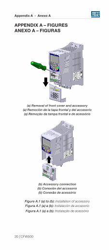
APPENDIX A – FIGURESANEXO A – FIGURAS
(a) Removal of front cover and accessory(a) Remoción de la tapa frontal y del accesorio(a) Remoção da tampa frontal e de acessório
(b) Accessory connection(b) Conexión del accesorio(b) Conexão de acessório
Figure A.1 (a) to (b): Installation of accessoryFigura A.1 (a) a (b): Instalación de accesorio
Figura A.1 (a) a (b): Instalação de acessório
Appendix A - Anexo A
CFW500 | 21
61.2
68.5
[2.4]
[2.7]
22.6
[0.9
]Figure A.2: CFW500-IOD dimensions in mm [in], DIP-
switches location and CFW500-MMF connectorFigura A.2: Dimensiones del CFW500-IOD en mm
[in], localización de las DIP-switches y conectador de CFW500-MMF
Figura A.2: Dimensões do CFW500-IOD em mm [in], localização das DIP-switches e conector do CFW500-MMF
NOTES / NOTAS / ANOTAÇÕES
Doc
umen
t: 10
002
0465
84 /
02
11770661
WEG Drives & Controls - Automação LTDA.Jaraguá do Sul - SC - Brazil Phone 55 (47) 3276-4000 - Fax 55 (47) 3276-4020São Paulo - SP - Brazil Phone 55 (11) 5053-2300 - Fax 55 (11) [email protected]