13
DIGITAL LOGIC WITH VHDL (Fall 2013) Unit 6 FINITE STATE MACHINES (FSMs) Moore Machines Mealy Machines Instructor: Daniel Llamocca
DIGITAL LOGIC WITH VHDL (Fall 2013)
Unit 6
FINITE STATE MACHINES (FSMs)
Moore Machines
Mealy Machines
Instructor: Daniel Llamocca

FINITE STATE MACHINES (FSMs) Classification:
Moore Machine: Outputs depend only on the current state of the
circuit.
Mealy Machine: Outputs depend on the current state of the circuit
as well as the inputs of the circuit.
The circuit must always start from an initial state. Thus, there should
be a ‘resetn’ signal. The figure depicts a generic state machine:
Instructor: Daniel Llamocca
Combinatorial
CircuitFlip Flops
Combinatorial
Circuit
Inputs Q (States)
clock
resetn
Only for Mealy Machine
Outputs

FINITE STATE MACHINES (FSMs) VHDL Coding: There exist many different styles. The style
explained here considers two processes: one for the state
transitions, and another for the outputs.
The first step is to have the state diagram ready. The coding
then just simply follows the state diagram.
We need to define a custom user data type (e.g., “state”) to
represent the states
type state is (S1, S2, ... S10) – example with 10 states
signal y: state;
Then, we define a signal of type “state” (e.g. ‘y’). This signal
can only take values from S1 to S10.
Two processes must be considered:
One where state transitions occur on the clock edge.
One where the outputs are defined based on the current
state and input signals.
Instructor: Daniel Llamocca

Moore Machine
Example: 2-bit counter
Counter: 00 01 10 10 00 …
Instructor: Daniel Llamocca
2-bit
counter
resetn
clock
Q2
Q = 0
S1
Q = 1
Q = 2Q = 3
S2
S3S4
resetn = '0'
Custom datatype definition: ‘state’
with 4 possible values: S1 to S4
Definition of signal ‘y’
of type ‘state’.
Process that
defines the
state
transitions
library ieee;
use ieee.std_logic_1164.all;
entity my_2bitcounter is
port ( clock, resetn: in std_logic;
Q: out std_logic_vector (1 downto 0));
end my_2bitcounter;
architecture bhv of my_2bitcounter is
type state is (S1,S2,S3,S4);
signal y: state;
begin
Transitions: process (resetn, clock)
begin
if resetn = '0' then -- asynchronous signal
y <= S1; -- initial state
...

2-bit counter
Instructor: Daniel Llamocca
2-bit
counter
resetn
clock
Q2
Process that defines
the state transitions
Note that the state
transitions only
occur on the rising
clock edge
Process that defines
the outputs
Note that the output is
not controlled by the
rising clock edge, only by
the current state.
Note that the outputs only depend
on the current state, hence this is
a Moore machine
...
elsif (clock'event and clock='1') then
case y is
when S1 => y <= S2;
when S2 => y <= S3;
when S3 => y <= S4;
when S4 => y <= S1;
end case;
end if;
end process;
Outputs: process (y)
begin
case y is
when S1 => Q <= "00";
when S2 => Q <= "01";
when S3 => Q <= "10";
when S4 => Q <= "11";
end case;
end process;
end bhv;
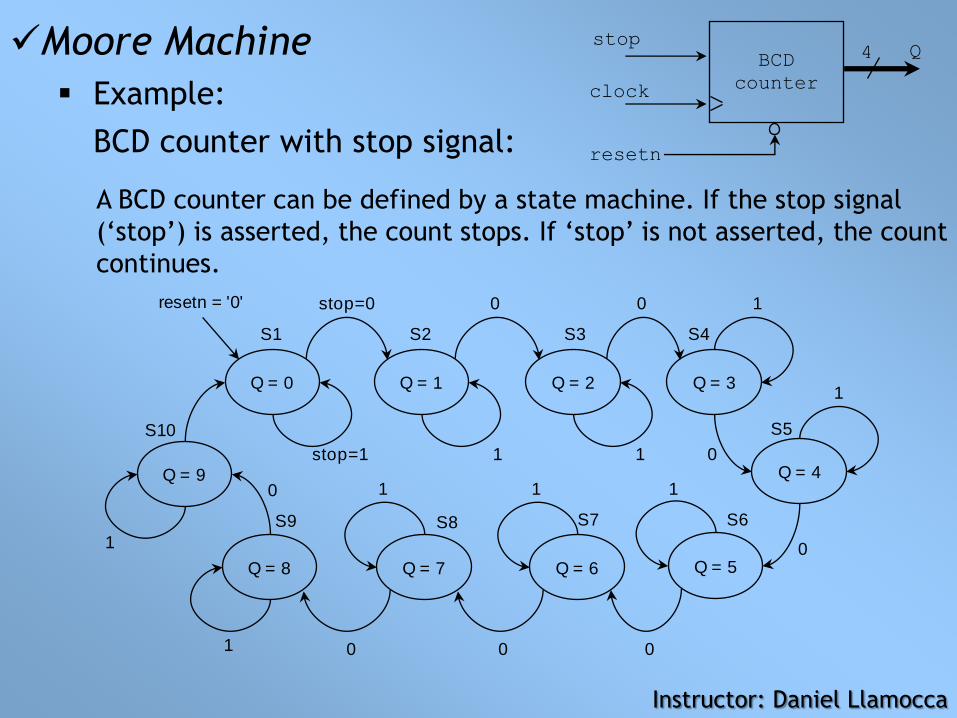
Moore Machine
Example:
BCD counter with stop signal:
A BCD counter can be defined by a state machine. If the stop signal
(‘stop’) is asserted, the count stops. If ‘stop’ is not asserted, the count
continues.
Instructor: Daniel Llamocca
BCD
counter
resetn
clock
Q4stop
Q = 0
S1
Q = 1 Q = 2 Q = 3
Q = 4
Q = 5Q = 6
Q = 9
Q = 7Q = 8
S2 S3 S4
S5
S6S7S8S9
S10
stop=1
stop=0
1 1
0 0 1
0
1
000
0
0
111
1
1
resetn = '0'
library ieee;
use ieee.std_logic_1164.all;
entity bcd_count is
port ( clock, resetn, stop: in std_logic;
Q: out std_logic_vector (3 downto 0));
end bcd_count;
architecture bhv of bcd_count is
type state is (S1,S2,S3,S4,S5,S6,S7,S8,S9,S10);
signal y: state;
begin
Transitions: process (resetn, clock, stop)
begin
if resetn = '0' then -- asynchronous signal
y <= S1; -- initial state
...
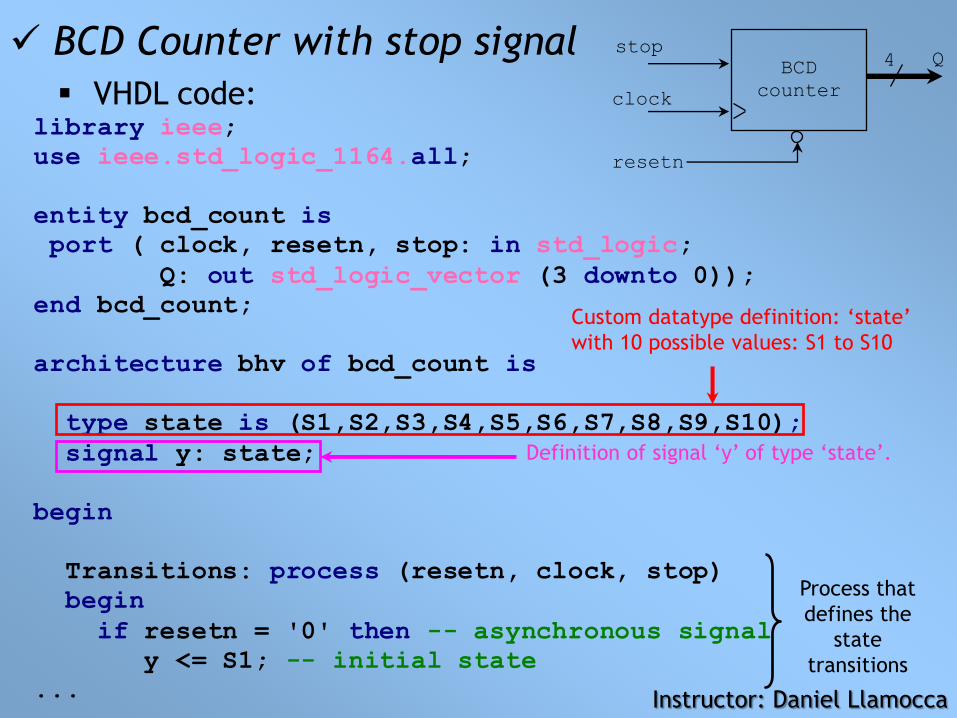
BCD Counter with stop signal
VHDL code:
Custom datatype definition: ‘state’
with 10 possible values: S1 to S10
Definition of signal ‘y’ of type ‘state’.
Process that
defines the
state
transitions
Instructor: Daniel Llamocca
BCD
counter
resetn
clock
Q4stop

...
elsif (clock'event and clock='1') then
case y is
when S1 =>
if stop='1' then y<=S1; else y<=S2; end if;
when S2 =>
if stop='1' then y<=S2; else y<=S3; end if;
when S3 =>
if stop='1' then y<=S3; else y<=S4; end if;
when S4 =>
if stop='1' then y<=S4; else y<=S5; end if;
when S5 =>
if stop='1' then y<=S5; else y<=S6; end if;
when S6 =>
if stop='1' then y<=S6; else y<=S7; end if;
when S7 =>
if stop='1' then y<=S7; else y<=S8; end if;
when S8 =>
if stop='1' then y<=S8; else y<=S9; end if;
when S9 =>
if stop='1' then y<=S9; else y<=S10; end if;
when S10 =>
if stop='1' then y<=S10; else y<=S1; end if;
end case;
end if;
end process;
...
Process that defines
the state transitions
Note that the state
transitions only
occur on the rising
clock edge
Note that the state
transitions depend
on the stop signal
‘stop’
Instructor: Daniel Llamocca

BCD Counter with stop signal
VHDL code:
Process that defines
the outputs
Note that the output is not controlled
by the rising clock edge, only by the
current state.
Note that the outputs only depend
on the current state, hence this is a
Moore machine
Instructor: Daniel Llamocca
BCD
counter
resetn
clock
Q4stop
...
Outputs: process (y)
begin
case y is
when S1 => Q <= "0000";
when S2 => Q <= "0001";
when S3 => Q <= "0010";
when S4 => Q <= "0011";
when S5 => Q <= "0100";
when S6 => Q <= "0101";
when S7 => Q <= "0110";
when S8 => Q <= "0111";
when S9 => Q <= "1000";
when S10 => Q <= "1001";
end case;
end process;
end bhv;

MEALY MACHINE
Example: sequence detector
(‘11010’) with overlap.
State Diagram: 5 states
Instructor: Daniel Llamocca
Detector
'11010'
resetn
clock
zx
S1 S2
S3
S5 S4
resetn = '0'0/0 1/0
0/01/0
1/0
0/00/0
1/0
0/1
1/0
Notation: x/z

library ieee;
use ieee.std_logic_1164.all;
entity my_seq_detect is
port ( clock, resetn, x: in std_logic;
z: out std_logic);
end my_seq_detect;
architecture bhv of my_seq_detect is
type state is (S1,S2,S3,S4,S5);
signal y: state;
begin
Transitions: process (resetn, clock, x)
begin
if resetn = '0' then -- asynchronous signal
y <= S1; -- initial state
... Instructor: Daniel Llamocca
MEALY MACHINE
Example: equence detector
(‘11010’) with overlap.
Detector
'11010'
resetn
clock
zx
Custom datatype definition: ‘state’
with 5 possible values: S1 to S5
Definition of signal ‘y’ of type ‘state’.
Process that defines
the state transitions

Process that defines
the state transitions
Instructor: Daniel Llamocca
MEALY MACHINE
Example: sequence detector
(‘11010’) with overlap.
Detector
'11010'clock
zx
Note that the state
transitions depend
on the input signal
‘x’
Note that the state
transitions only
occur on the rising
clock edge
...
elsif (clock'event and clock='1') then
case y is
when S1 =>
if x = '1' then y<=S2; else y<=S1; end if;
when S2 =>
if x = '1' then y<=S3; else y<=S1; end if;
when S3 =>
if x = '1' then y<=S3; else y<=S4; end if;
when S4 =>
if x = '1' then y<=S5; else y<=S1; end if;
when S5 =>
if x = '1' then y<=S3; else y<=S1; end if;
end case;
end if;
end process;
...

Process that
defines the
outputs
Note that the output
depends on the current
state and the input ‘x’,
hence this is a Mealy
machine.
Instructor: Daniel Llamocca
MEALY MACHINE
Example: sequence detector
(‘11010’) with overlap.
Detector
'11010'clock
zx
...
Outputs: process (x,y)
begin
z <= '0';
case y is
when S1 =>
when S2 =>
when S3 =>
when S4 =>
when S5 =>
if x = '0' then z <= '1'; end if;
end case;
end process;
end bhv;


