Digital optical computing with symbolic substitution
Karl-Heinz Brenner, Alan Huang, and Norbert Streibl
Symbolic substitution logic is based on optical pattern transformations. This space-invariant mechanism isshown to be capable of supporting space-variant operations. An optical implementation is proposed. It isbased on splitting an image, shifting the split images, superimposing the results, regenerating the superim-posed image with an optical logic array, splitting the regenerated image, shifting the resulting images, andsuperimposing the shifted images. Experimental results are presented. Examples demonstrate how sym-bolic substitution logic can be used to implement Boolean logic, binary arithmetic, cellular logic, and Turingmachines.
I. Introduction
In principle it would be possible to emulate all theparts of an electronic computer with optical compo-nents. The electronic gate could be replaced by theoptical logic gate, while the wires could be replaced byoptical fibers. Such an approach is convenient in therespect that all the existing knowledge could be trans-formed directly. However, this approach would nottake full advantage of the capabilities and advantagesof optical signal processing. When building an opticalcomputer we have to consider the fact that the archi-tecture of the electronic computer has evolved fromthe specific conditions existing in electronics. What isoptimal for (1-D) electronics is not necessarily optimalfor 3-D optics. As a result, the viability of an opticaldigital computer depends heavily on finding the rightalgorithms and architectures which favor optics.
II. Symbolic Substitution
Symbolic substitution was first proposed by Huang1
as a means of utilizing the parallelism of optics. Insymbolic substitution, the operators involve recogniz-ing all the occurrences of a particular pattern within animage and replacing these occurrences with anotherpattern. Symbolic substitution differs from tradi-tional Boolean logic in the respect that a Boolean oper-ator, such as AND and NOR, recognizes a combinationof bits and outputs one bit (see Fig. 1, top), whilesymbolic substitution recognizes not only a combina-
The authors are with AT&T Bell Laboratories, Holmdel, NewJersey 07733.
tion of bits but also the relative location of these bitsand outputs not just a single bit as in the case ofBoolean logic but rather a combination of bits posi-tioned in a particular manner (see Fig. 1, bottom).Symbolic substitution is a superset of Boolean logic inthe respect that it is sensitive to both the value of thebits and their spatial location. This gives symbolicsubstitution another degree of freedom. A more for-mal discussion of symbolic substitution is given in theAppendix.
A. Optical Symbolic Substitution
Symbolic substitution can be decomposed into arecognition and substitution phase. This is illustratedin Figs. 2-4. Suppose we had an image Io, whichconsists of a mosaic of two by two patterns. Assumingthat the pattern origin is defined as I(x X 2 + 0, y X 2 +0), i.e., the lower left corner, and suppose we wanted torecognize all the occurrences of a pattern consisting ofdark pels on the main diagonal Io(x X 2 + 0, y X 2 + 1)and Io(x X 2 + 1, y X 2 + 0) and two bright pels on theoff-diagonal and then replace this pattern with a twoby two pattern with dark pels on the off-diagonal, I5(xX 2 + 0, y X 2 + 0) and 15 (x X 2 + 1, y X 2 + 1), andbright pels on the diagonal. This could be accom-plished by
making two copies, I and I2, of the image;shifting one image I so that one of the dark pels on
the diagonal, I(x X 2 + 0, y X 2 + 1), is shifted downone pel, I (x X 2 + 0, y X 2 + 1 - 1), onto the pattern or-igin,Ii(x X 2 + 0,y X 2 + 0);
shifting the other image I2 so that the other dark pel,I2 (x X 2 + 1, y X 2 + 0), is shifted one pel left onto thepattern origin, I(x X 2 + 1 - 1, y X 2 + 0);
superimposing the two resulting images, I(x X 2 + 0,y X 2 + 1-1) +I 2(x X 2 + 1- 1,y X 2 + 0);
feeding this superimposed image to an array of opti-
Fig. 1. Comparison of Boolean logic with symbolic substitution.
OMEInvertedPattern
Mask
- monoE
RecognitionOutput
Fig. 3. Inversion and masking. The NOR gate transforms darkspots into bright spots, and the mask selects only those that are inthe lower left cell. The two search patterns contained in the input
I ShiftFig. 2. Recognition of the search pattern. The output is a superpo-sition of two shifted copies of the input pattern. The shift is deter-mined so that for a search pattern the dark spots superpose on the
lower left cell.
cal NOR gates which will produce a bright output corre-sponding to each input pel which is still dark;
masking the NOR gate array output with a mask,M(x X 2 + 0, y X 2 + 0), which excludes all but thepattern origin outputs (note: all the bright pels nowmark all the occurrences of the search pattern);
Shift
Fig. 4. Substitution of the scribing pattern. The output is a super-position of two shifted copies of the input pattern. The shift is
selected to scribe the new pattern.
making two copies, I3 and I4, of the masked NOR gateoutput;
shifting image I3 one pel upward, I3(x X 2 + 0, y X 2 +1);
shifting image I4 one pel to the left, I4(x X 2 + 1, y X 2+ 0); and
superimposing the resulting images, I 3(x X 2 + 0, y X2 + 1) + I4 (x X 2 + 1, y X 2 + 0), to generate the newpattern consisting of two dark pels on the off-diagonaland bright pels on the diagonal.
The operations described implement one rule. Towork with more than one rule we must first produce
Fig. 5. Architecture for an optical symbolic substitution processor.The pattern splitter provides four copies of the input plane. Everypattern recognizer-pattern substituter pair is implementing a dif-ferent rule. The pattern combiner recombines the partial outputs
of the pattern substituters in the output plane.
Mirror
.~~~~~...
Input
-D I iA
Fig. 6. Optical superposition of shifted images in a Michelsoninterferometer. The output plane is an image of the input plane.
The tilt of the mirrors determines the shifts.
several copies of the input, provide them to differentrecognizer-substituter units, and then combine theoutputs of the various units to form a new output.This is illustrated in Fig. 5.
B. Implementation of Optical Symbolic Substitution
The first step in recognizing a symbol is to generate atwofold image of the input data. This space-invariantoperation is easy to implement optically. Figure 6shows how such a twofold image can be accomplished.This is an example of a general class of methods that werefer to as interferometric methods. The schemeshown is essentially a Michelson interferometer exceptfor the fact that we use imaging and the mirrors aretilted. The tilt of the mirrors determines the shift ofthe images with respect to each other. This unit canbe used in both the recognition and substitution phase,since both phases require producing twofold shiftedimages.
The energy efficiency of the setup can be improvedby using a polarizing beam splitter and quarterwave
Output
Fig. 7. Optical superposition of shifted images in a Sagnac interfer-ometer. The output plane is an image of the input plane. The tilt of
the mirrors determines the shifts.
plates between mirror and cube. Figure 7 shows aconfiguration which utilizes polarization but does notrequire quarterwave plates. It is essentially a Sagnac-type interferometer. Half of the input is reflected twotimes and travels clockwise; the other half is transmit-ted two times and travels counterclockwise. Interest-ingly, this setup guarantees that the path length ofboth arms is equal up to 1/10 mm (depending on thetilt) which corresponds to time differences of 300 fs, afigure hard to achieve in electronics.
Both the Michelson and Sagnac configuration pro-duce a shift by tilting the image plane. This is unde-sirable in the case where timing considerations restrictthe path length difference to less than a wavelength oralso in the case where the optical logic gate is a direc-tion sensitive device such as a Fabry-Perot etalon.For these situations, Fig. 8 shows an arrangementwhich allows shifting without tilting the image planes.To equalize the path length in both arms, an optionalpath length compensating delay can be added in onebranch.
Other possibilities of producing twofold and shiftedimages are holographic methods and polarizationmethods. With holographic methods shifted imagescan be achieved by holograms of two-point objects.Polarization methods involve exploiting the two polar-ization states of light. One such approach would be touse birefringent crystals, like calcite or quartz, to du-plicate and displace an image.
Possible candidates for the optical NOR gates used toregenerate the image between the recognition and gen-eration phase of symbolic substitution are the optical
Fig. 8. Optical superposition of shifted images without tilting theimage plane. The shift is determined by the position of the movable
lens-mirror combination.
logical etalon2 and the self-electrooptic effect device(SEED). 3
C. Experimental Results
Figure 9 shows experimental results of a recognizer.The optical setup was similar to that shown in Fig. 6.The top shows the input pattern, containing manytarget patterns as well as other patterns consisting oftwo dark and two bright spots in a 2 X 2 cell. The taskof the recognizer is to locate all the occurrences of thetarget pattern and to produce a dark spot in the corre-sponding reference cell. The optical result is shown inthe lower part of Fig. 9.
D. Some Practical Details
Given an arbitrary pattern it would be necessary toexamine both the ones and zeros to recognize fully thepattern. This could be accomplished by using a NORgate to examine the locations where the zeros shouldbe, using an AND gate to examine the locations wherethe ones should be, and then combining both resultswith an AND gate. This situation is rather difficult andcan be avoided by coding the information in a dual-railmanner.4 In this type of coding, a bit of information isrepresented by two pels where one pel is always thecomplement of the other. This can be viewed also aspositional coding, since the information is representedby the position of a bright spot rather than by itsintensity. This type of coding simplifies the recogni-tion phase of symbolic substitution, since the codingmakes it only necessary to examine either the bright or
Fig. 9. Input pattern and result of the recognizer. The searchpattern is the same as in Fig. 2.
the dark pels of a pattern. The equivalence is guaran-teed by the coding.
If we want to only examine the one pels, we have touse an AND operation. If we want to recognize only thezeropels, we have to use a NOR operation. From thelogical point of view, both are equivalent. From apractical point of view the NOR is favored, because weonly have to distinguish between no light and one unitof light intensity, while in the AND case we would haveto distinguish between one and two units of light inten-sity. The NOR case needs a SNR of better than one,while the AND case needs it to be better than two.
In addition to simplifying the' recognition phasedual-rail coding is also preferable from the viewpointof energy balancing since it guarantees a homogeneousdistribution of energy.
The 2 X 2 patterns which we have been using seemquite restricted. However, given the assumption that
L. . ... ! ..... A ......,;, . ..................................
-' ' Polarizing Beam Splitter
Input
III:1... iI �
1.I
:1 � ,
:iaI " �1. �i
: I '.: . i
.. I� f =�-:...... .......1 .... ; - ;
H ZERO El ONE
N = ZERO
W =ONE
(0.0) - > 10,1 ) - > 1 (1 ,o) - > 1 (1 ,j) - >
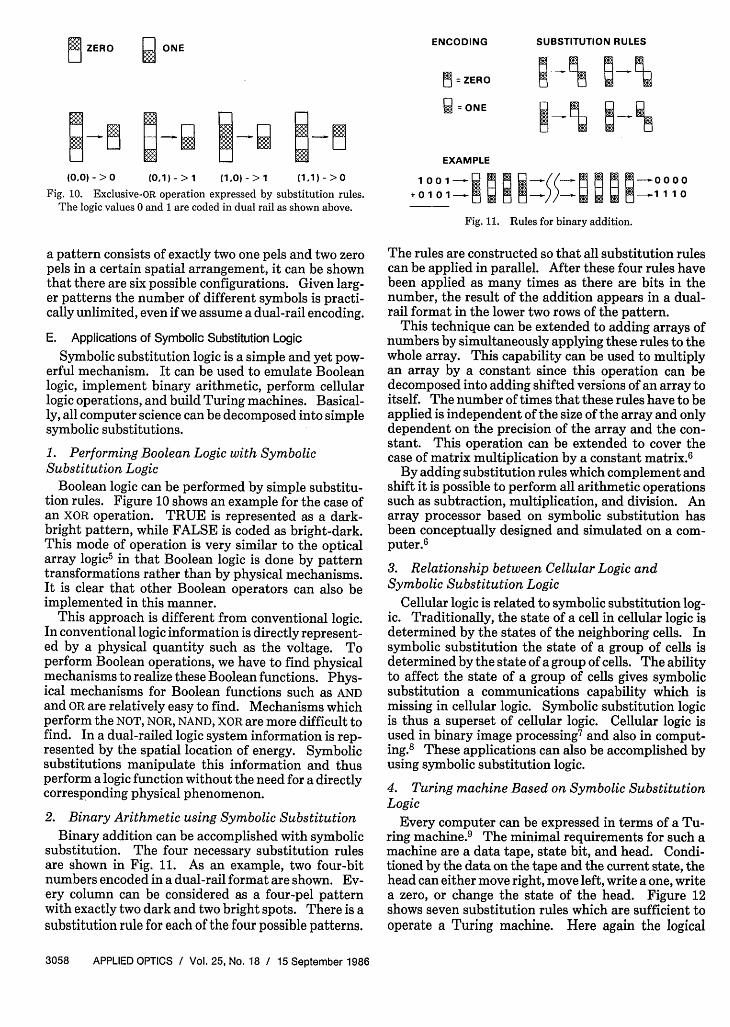
Fig. 10. Exclusive-OR operation expressed by substitution rules.The logic values 0 and 1 are coded in dual rail as shown above.
a pattern consists of exactly two one pels and two zeropels in a certain spatial arrangement, it can be shownthat there are six possible configurations. Given larg-er patterns the number of different symbols is practi-cally unlimited, even if we assume a dual-rail encoding.
E. Applications of Symbolic Substitution Logic
Symbolic substitution logic is a simple and yet pow-erful mechanism. It can be used to emulate Booleanlogic, implement binary arithmetic, perform cellularlogic operations, and build Turing machines. Basical-ly, all computer science can be decomposed into simplesymbolic substitutions.
1. Performing Boolean Logic with SymbolicSubstitution Logic
Boolean logic can be performed by simple substitu-tion rules. Figure 10 shows an example for the case ofan XOR operation. TRUE is represented as a dark-bright pattern, while FALSE is coded as bright-dark.This mode of operation is very similar to the opticalarray logic5 in that Boolean logic is done by patterntransformations rather than by physical mechanisms.It is clear that other Boolean operators can also beimplemented in this manner.
This approach is different from conventional logic.In conventional logic information is directly represent-ed by a physical quantity such as the voltage. Toperform Boolean operations, we have to find physicalmechanisms to realize these Boolean functions. Phys-ical mechanisms for Boolean functions such as ANDand OR are relatively easy to find. Mechanisms whichperform the NOT, NOR, NAND, XOR are more difficult tofind. In a dual-railed logic system information is rep-resented by the spatial location of energy. Symbolicsubstitutions manipulate this information and thusperform a logic function without the need for a directlycorresponding physical phenomenon.
2. Binary Arithmetic using Symbolic SubstitutionBinary addition can be accomplished with symbolic
substitution. The four necessary substitution rulesare shown in Fig. 11. As an example, two four-bitnumbers encoded in a dual-rail format are shown. Ev-ery column can be considered as a four-pel patternwith exactly two dark and two bright spots. There is asubstitution rule for each of the four possible patterns.
EXAMPLE
1 001 b; ! m; t(( b m ! ! 0 000+ 1 0 1 1 1 1
Fig. 11. Rules for binary addition.
The rules are constructed so that all substitution rulescan be applied in parallel. After these four rules havebeen applied as many times as there are bits in thenumber, the result of the addition appears in a dual-rail format in the lower two rows of the pattern.
This technique can be extended to adding arrays ofnumbers by simultaneously applying these rules to thewhole array. This capability can be used to multiplyan array by a constant since this operation can bedecomposed into adding shifted versions of an array toitself. The number of times that these rules have to beapplied is independent of the size of the array and onlydependent on the precision of the array and the con-stant. This operation can be extended to cover thecase of matrix multiplication by a constant matrix.6
By adding substitution rules which complement andshift it is possible to perform all arithmetic operationssuch as subtraction, multiplication, and division. Anarray processor based on symbolic substitution hasbeen conceptually designed and simulated on a com-puter.6
3. Relationship between Cellular Logic andSymbolic Substitution Logic
Cellular logic is related to symbolic substitution log-ic. Traditionally, the state of a cell in cellular logic isdetermined by the states of the neighboring cells. Insymbolic substitution the state of a group of cells isdetermined by the state of a group of cells. The abilityto affect the state of a group of cells gives symbolicsubstitution a communications capability which ismissing in cellular logic. Symbolic substitution logicis thus a superset of cellular logic. Cellular logic isused in binary image processing7 and also in comput-ing.8 These applications can also be accomplished byusing symbolic substitution logic.
4. Turing machine Based on Symbolic SubstitutionLogic
Every computer can be expressed in terms of a Tu-ring machine.9 The minimal requirements for such amachine are a data tape, state bit, and head. Condi-tioned by the data on the tape and the current state, thehead can either move right, move left, write a one, writea zero, or change the state of the head. Figure 12shows seven substitution rules which are sufficient tooperate a Turing machine. Here again the logical
LHS RHS LHS RHS0-0000 000000 000000 000000000000 000000 000000 000000000000 000000 000000 000000000000 000000 000000 000000000000 000000 000000 000000MO000 O00000 000000 000000Fig. 12. Rules for a Turing machine. Rules 3..6 are modeled to bethe state machine of a counter. The other rules maintain the tape
information and activity bits.
values zero and one are encoded in a dual-rail fashion.The top position is simply an alignment marker whichassures that the recognizer fires only if the alignmentof the pattern is correct. The next two positions arethe tape. A ZERO state is represented on the tape by abright-dark sequence, while a ONE state is represent-ed by a dark-bright sequence. The next three posi-tions hold the state information of the head. A darkspot at the top indicates that the head is in a ONEstate, a dark spot in the middle indicates a ZERO state,and a dark spot at the bottom indicates that the head isnot present at this location on the tape.
The first two rules in Fig. 12 maintain the informa-tion on the tape. The last rule preserves the head-not-present bit. The remaining four rules determine theoperation of the machine. They specify what happensin the situations (tape = 0, state = 0), (tape = 0, state =1), etc.
Figure 13 shows an initial situation of all zeros on thetape and the head with state zero in the rightmostposition. By applying the rules shown in Fig. 12 re-peatedly in parallel the head will continue to incre-ment the binary number on the tape.
This technique can be extended and used to imple-ment a universal Turing machine, and such a machinecan be used to compute anything which is computable.Furthermore, this example demonstrates that a space-invariant optical architecture is also able to performspace-variant operations. By positioning a secondTuring tape and head below the first one, two Turingmachines are made to operate simultaneously. If thedata on both tapes are different, these Turing ma-chines will perform different functions.
1ll. Summary
The parallel space-invariant nature of optics is fun-damentally different from the serial space-variant na-ture of electronics and requires a different approach to
00000000000000000000000000000000000000000000o. u 0 m0.000000000000000 0000000000000000000000000000000000000000000000000000000000000000000000000000000000000000000000000000000000000000000000000000 0000000000000000000000000000000000000000000000000000000000000000000000000000000000000000000000000000000000000000000000000000000000000000000000000000000000000000000000000000000000000000000000000000000000000000000000000000000000000000000000000000000000000000000000000000000000000000000000000000000000000000000000000000000000000000000000000000000
00000000-0000000000000000000000001
Fig. 13. Initial condition for the Turing machine. The top row isalignment markers. The next two rows are the tape in dual railcoding. All positions are zero. The following three rows contain thestate information of the head. It is inactive on most locations and
zero at the location of the head.
computation. Symbolic substitution is a simple andyet powerful logic system which facilitates the designof circuits with constant fan-in, constant fan-out, andregular interconnections. The constant fan-in andconstant fan-out simplify the demands on the opticallogic gates, while the regular interconnections matchthe space-invariant connectivity of optics. Althoughsymbolic substitution is based on space-invariant in-terconnections it is not restricted to space-invariantoperations. The example of emulating a Turing ma-chine demonstrates that space-variant operations canalso be performed.
We discuss what symbolic substitution is, how it canbe implemented using classical optics and optical non-linearities, and how it can be used to implement Bool-ean logic, binary arithmetic, cellular logic, and Turingmachines.
When this work was done K. H. Brenner was on leavefrom the University of Erlangen-Nurnberg, F.R. Ger-many.
Appendix
Symbolic substitution logic can be described in moreformal terms in the following manner: If the inputdata plane d(r) is an array of logical values 0 and 1, andr is a 2-D position vector with discrete components, apattern Pm is described by its logical values f andtheir corresponding spatial locations s relative tosome origin. Recognition of a pattern Pm at location rcan be achieved by a comparison operation:
A[/f, d(r + s)]
and a superposition operationMA (ak) = ajAa2A* . . aM.k=1
(Al)
(A2)
The comparison operation A is the Boolean equiva-lence operation defined by
because we want to test for equality with a searchpattern. A is the logical AND function to enforce thatall the pels of a given pattern are equal to the searchpattern. The whole recognizing procedure can then bedefined as a mapping of the input data plane d(r) ontothe intermediate plane d'(r) as
M
d'(r) = A A[fk,d(r + sk)]-k=1
(A4)
Visually, the data plane is shifted according to the shiftvectors of the pattern and compared to each state ofthe pattern for this shift. Therefore, d' will be nonzeroonly if d(r + sk) is equal to the state value fk for all Mpels in the pattern, i.e., on those places, where thepattern Pm occurred. The next step is the substitu-tion, which requires that every logical one in d' isreplaced by a new pattern P. Now the output planed" is formed by writing the pattern Pn wherever thereis a logical one in d'. This can be achieved by ORingshifted versions of d':
Nd"(r) = A,d'(r - s)]. (A5)
k=1
The AND function A guarantees that the OR operationoccurs only for those shifts where fk is one. The recog-nition procedure described here results in what we calla complete recognition, because we require that a pat-tern and its comparison pattern have to be completelyequal with respect to the ones and the zeros. Otheralternatives are partial recognitions requiring equalityto the search pattern only with respect to either theones or the zeros. Such a partial recognition is suffi-cient in the case of dual-rail coding where every logicvalue appears in combination with its complement.
References1. A. Huang, "Parallel Algorithms for Optical Digital Computers,"
in Technical Digest, IEEE Tenth International Optical Com-puting Conference, (1983), pp. 13-17.
2. J. L. Jewell, Y. H. Lee, M. Warren, H. M. Gibbs, N. Peyghambar-ian, A. C. Gossard, and W. Wiegmann, "3-pJ, 82 MHz OpticalLogic Gates in a Room Temperature GaAs-AlGaAs Multiple-Quantum-Well Etalon," Appl. Phys. Lett. 46, 918 (1985).
3. D. A. B. Miller, D. S. Chemla, A. C. Damen, A. C. Gossard, W.Wiegmann, T. Wood, and C. Burrus, Appl. Phys. Lett. 45, 13(1984).
4. J. von Neumann, The Computer and the Brain (Yale U.P., NewHaven, 1958).
5. J. Tanida and Y. Ichioka, "Optical Parallel Array Logic System,"in Optics in Modern Science and Technology, ICO-13 Confer-ence Digest, Sapporo, 1984, p. 294.
6. M. J. Murdocca, "Techniques for Parallel Numeric and Non-Numeric Algorithm Design in Digital Optics," Master's Thesis,Rutgers U., New Brunswick, NJ (1984).
7. K. Preston, M. J. B. Duff, S. Levialdi, P. E. Norgren, and J.Toriwaki, "Basics of Cellular Logic with some Applications inMedical Image Processing," Proc. IEEE 67, 826 (1979).
8. S. Wolfram, "Universality and Complexity in Cellular Automa-ta," in Cellular Automata, Proceedings, Interdisciplinary Work-shop, Los Alamos, NM, 7-11 Mar. 1983, D. Farmer, T. Toffoli,and S. Wolfram, Eds. (North-Holland, Amsterdam, 1984), p. 1.
9. M. Minsky, Computation: Finite and Infinite Machines (Pren-tice-Hall, Englewood Cliffs, NJ, 1967).
Patter continued from page 3053
1oor >d
a0
aw0)30s
EE
10
E0oZ
1-MeV Electron Fluence, cm2
Fig. 10. Performances of lithium-counterdoped and conventionalcells are compared after irradiation with 1-MeV electrons.
art conventional n + p boron-doped silicon solar cells have the disadvantage ofrequiring annealing temperatures of 4000C or higher. At this temperature,irreversible damage to solar-cell-array components occurs. This precludesthe possibility of in situ annealing in space, which, if it were possible, wouldextend the useful space lifetime of solar-cell arrays in space.
It has long been recognized, by workers in space photovoltaics, that p-typesilicon is innately more radiation-resistant than n-type silicon. Since most ofthe radiation damage occurs in the cell base region, the present n + p lithium-counterdoped silicon solar cell retains the increased-radiation-resistance fea-ture of the p-type base with the added advantage offered by lithium, whichtends to increase further the radiation resistance of the cell. Hence, thepresent invention is more radiation-resistant than the conventional n + pboron-doped silicon cell currently used in space. This is demonstrated in Fig.10, where the lithium-counterdoped cells can be seen to produce more outputpower than the presently used, conventional n + p silicon cells, after irradia-tion by MeV electrons.
In addition to possessing increased radiation resistance, the lithium-coun-terdoped silicon solar cells show significant performance restoration whenannealed at a temperature of 1000C. The conventional silicon cells now usedin space require annealing temperatures of 4000C, or higher, to remove theradiation-induced degradation. Components of solar-cell arrays now used inspace, such as adhesives, degrade irreversibly at this high temperature and willnot degrade at 1000C. Thus, the present lithium-counterdoped solar celloffers the potential for in situ annealing in space, a process that would increasethe electrical power available from the solar-cell array during its use in spacemissions subject to the degrading particulate environment of space.
This work was done by Irving Weinberg and Henry Brandhorst of LewisResearch Center. Refer to LEW-14177.
Improved high/low junction silicon solar cellA method has been developed to raise the value of the open-circuit voltage in
silicon solar cells by incorporating a high/low junction in the cell emitter.
AluminumEmitter
Contact OxideLayer
pin Junction""' St-t
.~~~~~~~~~~~~u srt
Ohmic Contact
Fig. 11. In an oxide-charge-induced high/low emitter solar cell,electron accumulation layer is induced by a positive charge.