Page 1
www.DanaherMotion.com
Digital Servo Amplifier
SERVOSTAR®
601...620
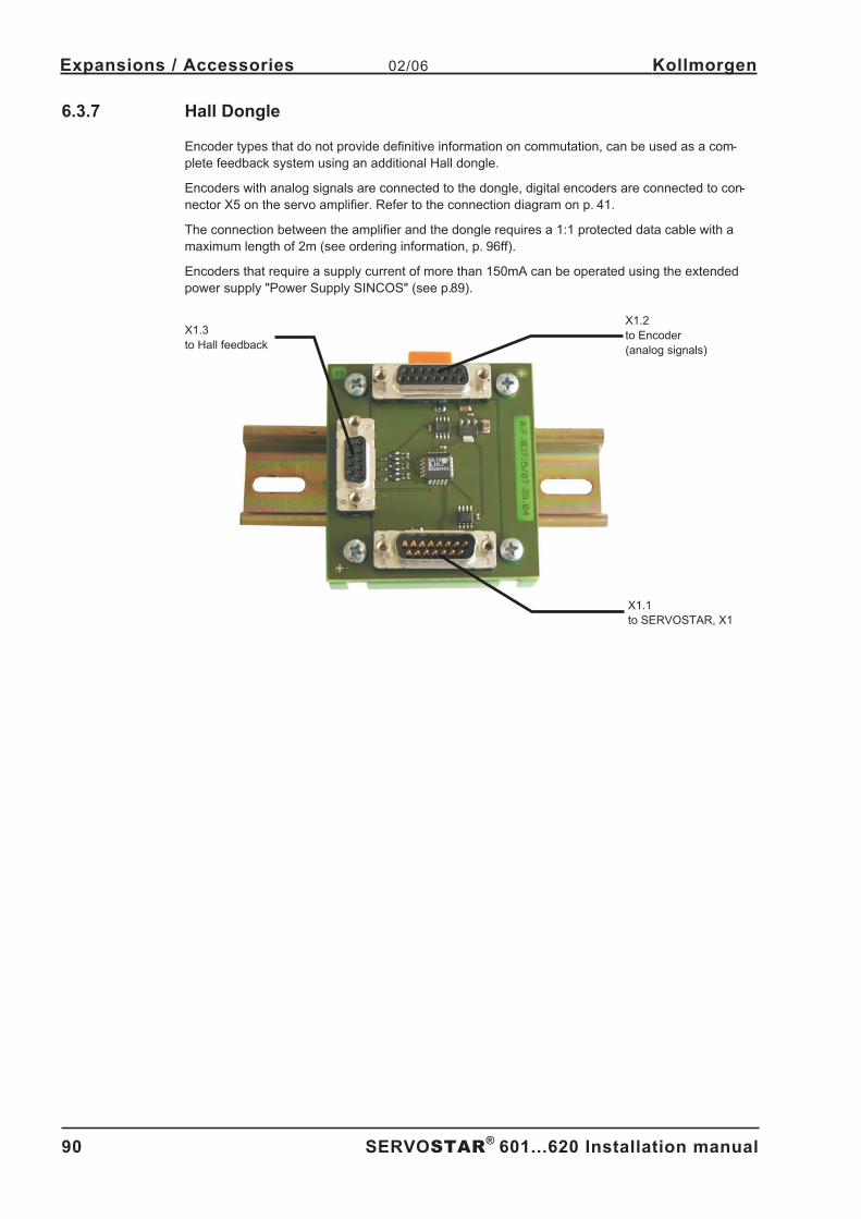
Assembly, Installation, SetupKeep all product manuals as a product component
during the life span of the servo amplifier.
Pass all product manuals to future
users / owners of the servo amplifier.
Edition 02/06
File sr601_d.xxx
Page 2
Previous versions :
Edition Remarks
05/98 First edition
08/98 a few corrections
09/98various minor corrections, parameter description removed, parameter setting for multi-axis systems and
on/off switching behavior added, Installation/setup divided into two chapters
01/99 614 added, various minor corrections
02/99 Interface relay for digital outputs (pages 26, 43)
06/99 various corrections, cables and connectors removed, choke box added
08/99 24V tolerance, encoder wiring, ventilation
11/99 Packaging, regen resistor
12/99 Option -AS- integrated, ground-bolt, master-slave
04/00 various corrections, setup software on CDROM only, motors 6SM27LL and 6SM37VL added
06/00 Wiring diagrams electr. gearing, warning and error messages, recommended torque
08/00 Wiring diagram in chapter III.9.2 corrected
07/01
S610-30 and options -I/O-14/08- and -2CAN - incorporated, hardware-description incorporated for
PROFIBUS and SERCOS, nameplate, motor list and connector assignment corrected, LED-display cor-
rected, error messages expanded
02/02 Dimensions BAR corrected
06/02Frontpage new design, corrections to US English, motor table removed, order numbers added,
last page new design and contents, new; connection to diff. mains supply networks, block diagram to ch.III
07/03several corrections, DeviceNet expansion card added, directives and standards page revised, new cover
design
09/03 Ethernet expansion card and Single axis controller expansion card added
03/04 new regen resistors BAR(U), several corrections
02/06
Company name updated, expansion cards updated, new sections on EtherCat and SynqNet, chapter l re-
structured, new sections on motor chokes, Encoder power supply and encoder termination, various error
corrections, new ordering codes, Feedback section revised, BAR removed, cross section (awg)
WINDOWS is a registered trademark of Microsoft Corp.
HIPERFACE is a registered trademark of Max Stegmann GmbH
EnDat is a registered trademark of Dr. Johannes Heidenhain GmbH
SERVOSTAR is a registered trademark of Kollmorgen Corporation.
Technical changes which improve the performance of the equipment may be made without prior notice !
Printed in the Federal Republic of Germany
All rights reserved. No part of this work may be reproduced in any form (by printing, photocopying, microfilm or any other method)
or stored, processed, copied or distributed by electronic means without the written permission of Danaher Motion Corporation.
Page 3
1 General1.1 About this manual . . . . . . . . . . . . . . . . . . . . . . . . . . . . . . . . . . . . . . . . . . . . . . . . . . . . . . . . . . . . . . . . . . . . . . . . . . . . . . . . . . . 7
1.2 Symbols used in this manual . . . . . . . . . . . . . . . . . . . . . . . . . . . . . . . . . . . . . . . . . . . . . . . . . . . . . . . . . . . . . . . . . . . . . . . . . . 7
1.3 Abbreviations used in this manual . . . . . . . . . . . . . . . . . . . . . . . . . . . . . . . . . . . . . . . . . . . . . . . . . . . . . . . . . . . . . . . . . . . . . . 8
2 Technical Description2.1 Safety Instructions . . . . . . . . . . . . . . . . . . . . . . . . . . . . . . . . . . . . . . . . . . . . . . . . . . . . . . . . . . . . . . . . . . . . . . . . . . . . . . . . . . 9
2.2 Use as directed . . . . . . . . . . . . . . . . . . . . . . . . . . . . . . . . . . . . . . . . . . . . . . . . . . . . . . . . . . . . . . . . . . . . . . . . . . . . . . . . . . . . 10
2.3 European Directives and Standards . . . . . . . . . . . . . . . . . . . . . . . . . . . . . . . . . . . . . . . . . . . . . . . . . . . . . . . . . . . . . . . . . . . . 11
2.4 CE conformance . . . . . . . . . . . . . . . . . . . . . . . . . . . . . . . . . . . . . . . . . . . . . . . . . . . . . . . . . . . . . . . . . . . . . . . . . . . . . . . . . . . 11
2.5 UL and cUL- Conformance . . . . . . . . . . . . . . . . . . . . . . . . . . . . . . . . . . . . . . . . . . . . . . . . . . . . . . . . . . . . . . . . . . . . . . . . . . . 12
2.6 Nameplate . . . . . . . . . . . . . . . . . . . . . . . . . . . . . . . . . . . . . . . . . . . . . . . . . . . . . . . . . . . . . . . . . . . . . . . . . . . . . . . . . . . . . . . 13
2.7 Instrument description . . . . . . . . . . . . . . . . . . . . . . . . . . . . . . . . . . . . . . . . . . . . . . . . . . . . . . . . . . . . . . . . . . . . . . . . . . . . . . 13
2.7.1 Package supplied . . . . . . . . . . . . . . . . . . . . . . . . . . . . . . . . . . . . . . . . . . . . . . . . . . . . . . . . . . . . . . . . . . . . . . . . . . . . 13
2.7.2 The digital servo amplifiers of the series SERVOSTAR 600. . . . . . . . . . . . . . . . . . . . . . . . . . . . . . . . . . . . . . . . . . . . 14
2.8 Connection to different mains supply networks . . . . . . . . . . . . . . . . . . . . . . . . . . . . . . . . . . . . . . . . . . . . . . . . . . . . . . . . . . . 16
2.9 Components of a servo system . . . . . . . . . . . . . . . . . . . . . . . . . . . . . . . . . . . . . . . . . . . . . . . . . . . . . . . . . . . . . . . . . . . . . . . 17
2.10 Technical data . . . . . . . . . . . . . . . . . . . . . . . . . . . . . . . . . . . . . . . . . . . . . . . . . . . . . . . . . . . . . . . . . . . . . . . . . . . . . . . . . . . . 18
2.10.1 Recommended torque. . . . . . . . . . . . . . . . . . . . . . . . . . . . . . . . . . . . . . . . . . . . . . . . . . . . . . . . . . . . . . . . . . . . . . . . . 19
2.10.2 Fusing . . . . . . . . . . . . . . . . . . . . . . . . . . . . . . . . . . . . . . . . . . . . . . . . . . . . . . . . . . . . . . . . . . . . . . . . . . . . . . . . . . . . . 19
2.10.2.1 Internal Fusing . . . . . . . . . . . . . . . . . . . . . . . . . . . . . . . . . . . . . . . . . . . . . . . . . . . . . . . . . . . . . . . . . . . . . . . . . . . 19
2.10.2.2 External fusing . . . . . . . . . . . . . . . . . . . . . . . . . . . . . . . . . . . . . . . . . . . . . . . . . . . . . . . . . . . . . . . . . . . . . . . . . . . 19
2.10.3 Allowable ambient conditions, ventilation, mounting position . . . . . . . . . . . . . . . . . . . . . . . . . . . . . . . . . . . . . . . . . . . 19
2.10.4 Conductor cross-sections . . . . . . . . . . . . . . . . . . . . . . . . . . . . . . . . . . . . . . . . . . . . . . . . . . . . . . . . . . . . . . . . . . . . . . 20
2.10.5 LED display . . . . . . . . . . . . . . . . . . . . . . . . . . . . . . . . . . . . . . . . . . . . . . . . . . . . . . . . . . . . . . . . . . . . . . . . . . . . . . . . . 20
2.11 Grounding system. . . . . . . . . . . . . . . . . . . . . . . . . . . . . . . . . . . . . . . . . . . . . . . . . . . . . . . . . . . . . . . . . . . . . . . . . . . . . . . . . . 20
2.12 Control for motor-holding brake . . . . . . . . . . . . . . . . . . . . . . . . . . . . . . . . . . . . . . . . . . . . . . . . . . . . . . . . . . . . . . . . . . . . . . . 21
2.13 Regen circuit . . . . . . . . . . . . . . . . . . . . . . . . . . . . . . . . . . . . . . . . . . . . . . . . . . . . . . . . . . . . . . . . . . . . . . . . . . . . . . . . . . . . . . 22
2.14 Switch-on and switch-off behavior . . . . . . . . . . . . . . . . . . . . . . . . . . . . . . . . . . . . . . . . . . . . . . . . . . . . . . . . . . . . . . . . . . . . . 23
2.14.1 Stop function to EN 60204 (VDE 0113). . . . . . . . . . . . . . . . . . . . . . . . . . . . . . . . . . . . . . . . . . . . . . . . . . . . . . . . . . . . 24
2.14.2 Emergency Stop strategies . . . . . . . . . . . . . . . . . . . . . . . . . . . . . . . . . . . . . . . . . . . . . . . . . . . . . . . . . . . . . . . . . . . . . 24
3 Installation3.1 Important instructions . . . . . . . . . . . . . . . . . . . . . . . . . . . . . . . . . . . . . . . . . . . . . . . . . . . . . . . . . . . . . . . . . . . . . . . . . . . . . . . 25
3.2 Guide to installation and wiring . . . . . . . . . . . . . . . . . . . . . . . . . . . . . . . . . . . . . . . . . . . . . . . . . . . . . . . . . . . . . . . . . . . . . . . . 26
3.3 Assembly . . . . . . . . . . . . . . . . . . . . . . . . . . . . . . . . . . . . . . . . . . . . . . . . . . . . . . . . . . . . . . . . . . . . . . . . . . . . . . . . . . . . . . . . 27
3.3.1 Dimensions . . . . . . . . . . . . . . . . . . . . . . . . . . . . . . . . . . . . . . . . . . . . . . . . . . . . . . . . . . . . . . . . . . . . . . . . . . . . . . . . . 28
3.4 Wiring . . . . . . . . . . . . . . . . . . . . . . . . . . . . . . . . . . . . . . . . . . . . . . . . . . . . . . . . . . . . . . . . . . . . . . . . . . . . . . . . . . . . . . . . . . . 29
3.4.1 Connection diagram . . . . . . . . . . . . . . . . . . . . . . . . . . . . . . . . . . . . . . . . . . . . . . . . . . . . . . . . . . . . . . . . . . . . . . . . . . 30
3.4.2 Example of connections for multi-axis system . . . . . . . . . . . . . . . . . . . . . . . . . . . . . . . . . . . . . . . . . . . . . . . . . . . . . . 31
3.4.3 Pin assignments . . . . . . . . . . . . . . . . . . . . . . . . . . . . . . . . . . . . . . . . . . . . . . . . . . . . . . . . . . . . . . . . . . . . . . . . . . . . . 32
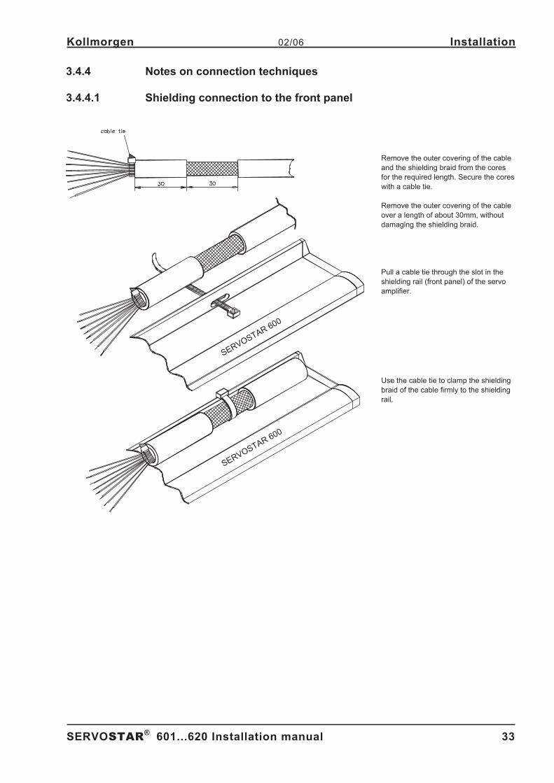
3.4.4 Notes on connection techniques . . . . . . . . . . . . . . . . . . . . . . . . . . . . . . . . . . . . . . . . . . . . . . . . . . . . . . . . . . . . . . . . . 33
3.4.4.1 Shielding connection to the front panel . . . . . . . . . . . . . . . . . . . . . . . . . . . . . . . . . . . . . . . . . . . . . . . . . . . . . . . . 33
3.4.4.2 Technical data for connecting cables . . . . . . . . . . . . . . . . . . . . . . . . . . . . . . . . . . . . . . . . . . . . . . . . . . . . . . . . . 34
3.5 Setup software . . . . . . . . . . . . . . . . . . . . . . . . . . . . . . . . . . . . . . . . . . . . . . . . . . . . . . . . . . . . . . . . . . . . . . . . . . . . . . . . . . . . 35
3.5.1 General . . . . . . . . . . . . . . . . . . . . . . . . . . . . . . . . . . . . . . . . . . . . . . . . . . . . . . . . . . . . . . . . . . . . . . . . . . . . . . . . . . . . 35
3.5.1.1 Use as directed . . . . . . . . . . . . . . . . . . . . . . . . . . . . . . . . . . . . . . . . . . . . . . . . . . . . . . . . . . . . . . . . . . . . . . . . . . 35
3.5.1.2 Software description . . . . . . . . . . . . . . . . . . . . . . . . . . . . . . . . . . . . . . . . . . . . . . . . . . . . . . . . . . . . . . . . . . . . . . 35
3.5.1.3 Hardware requirements . . . . . . . . . . . . . . . . . . . . . . . . . . . . . . . . . . . . . . . . . . . . . . . . . . . . . . . . . . . . . . . . . . . . 36
3.5.1.4 Operating systems. . . . . . . . . . . . . . . . . . . . . . . . . . . . . . . . . . . . . . . . . . . . . . . . . . . . . . . . . . . . . . . . . . . . . . . . 36
3.5.2 Installation under WINDOWS 95 / 98 / 2000 / ME / NT / XP. . . . . . . . . . . . . . . . . . . . . . . . . . . . . . . . . . . . . . . . . . . . 36
SERVOSTAR®
601...620 Installation manual 3
Kollmorgen 02/06 Contents
Page
Page 4
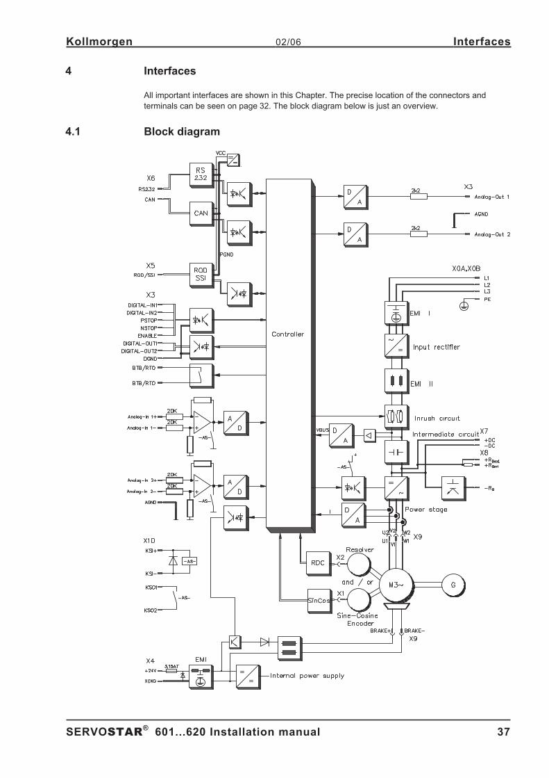
4 Interfaces4.1 Block diagram . . . . . . . . . . . . . . . . . . . . . . . . . . . . . . . . . . . . . . . . . . . . . . . . . . . . . . . . . . . . . . . . . . . . . . . . . . . . . . . . . . . . . 37
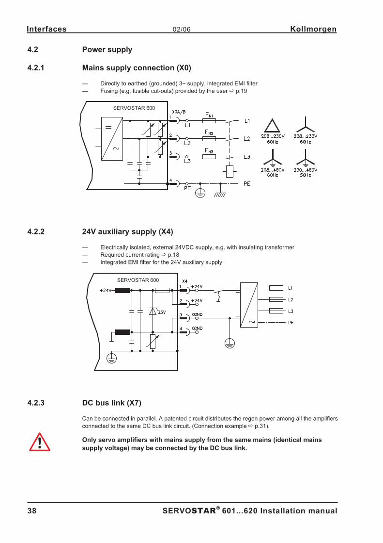
4.2 Power supply . . . . . . . . . . . . . . . . . . . . . . . . . . . . . . . . . . . . . . . . . . . . . . . . . . . . . . . . . . . . . . . . . . . . . . . . . . . . . . . . . . . . . 38
4.2.1 Mains supply connection (X0) . . . . . . . . . . . . . . . . . . . . . . . . . . . . . . . . . . . . . . . . . . . . . . . . . . . . . . . . . . . . . . . . . . . 38
4.2.2 24V auxiliary supply (X4). . . . . . . . . . . . . . . . . . . . . . . . . . . . . . . . . . . . . . . . . . . . . . . . . . . . . . . . . . . . . . . . . . . . . . . 38
4.2.3 DC bus link (X7) . . . . . . . . . . . . . . . . . . . . . . . . . . . . . . . . . . . . . . . . . . . . . . . . . . . . . . . . . . . . . . . . . . . . . . . . . . . . . 38
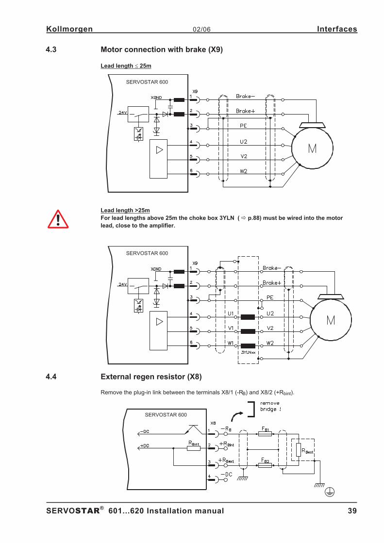
4.3 Motor connection with brake (X9) . . . . . . . . . . . . . . . . . . . . . . . . . . . . . . . . . . . . . . . . . . . . . . . . . . . . . . . . . . . . . . . . . . . . . . 39
4.4 External regen resistor (X8) . . . . . . . . . . . . . . . . . . . . . . . . . . . . . . . . . . . . . . . . . . . . . . . . . . . . . . . . . . . . . . . . . . . . . . . . . . 39
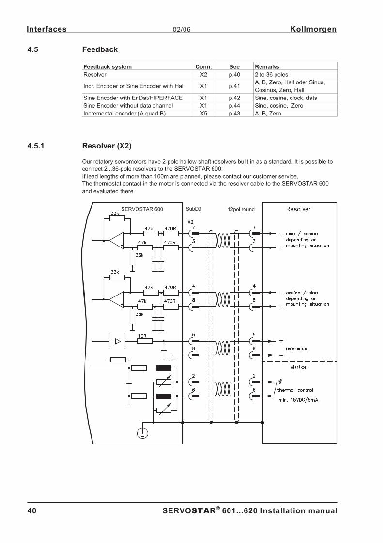
4.5 Feedback . . . . . . . . . . . . . . . . . . . . . . . . . . . . . . . . . . . . . . . . . . . . . . . . . . . . . . . . . . . . . . . . . . . . . . . . . . . . . . . . . . . . . . . . 40
4.5.1 Resolver (X2) . . . . . . . . . . . . . . . . . . . . . . . . . . . . . . . . . . . . . . . . . . . . . . . . . . . . . . . . . . . . . . . . . . . . . . . . . . . . . . . 40
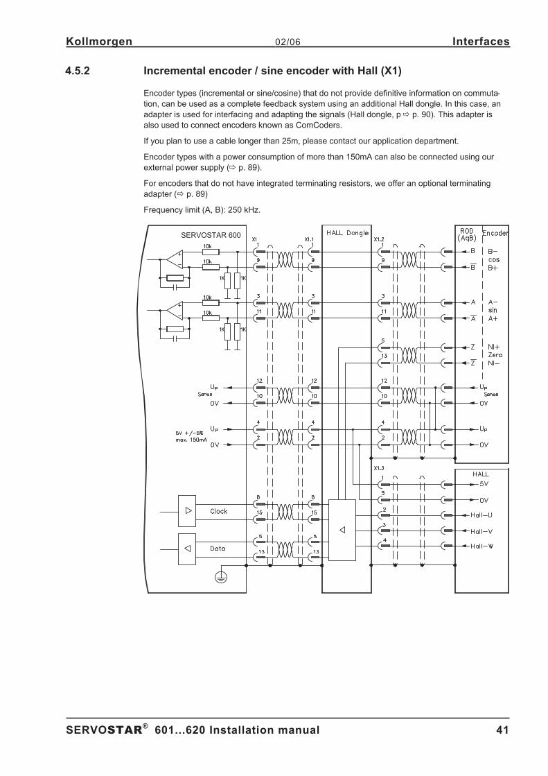
4.5.2 Incremental encoder / sine encoder with Hall (X1) . . . . . . . . . . . . . . . . . . . . . . . . . . . . . . . . . . . . . . . . . . . . . . . . . . . 41
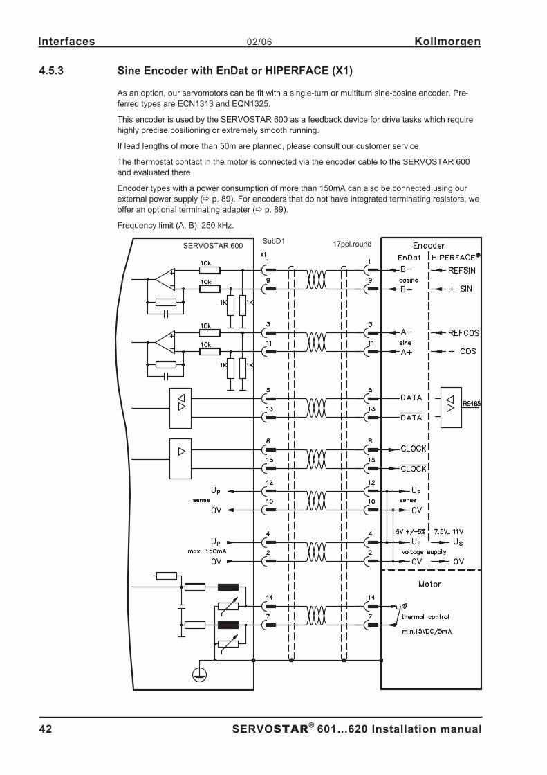
4.5.3 Sine Encoder with EnDat or HIPERFACE (X1) . . . . . . . . . . . . . . . . . . . . . . . . . . . . . . . . . . . . . . . . . . . . . . . . . . . . . . 42
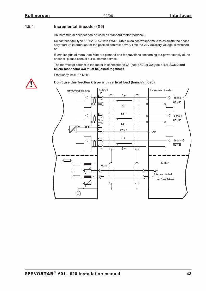
4.5.4 Incremental Encoder (X5) . . . . . . . . . . . . . . . . . . . . . . . . . . . . . . . . . . . . . . . . . . . . . . . . . . . . . . . . . . . . . . . . . . . . . . 43
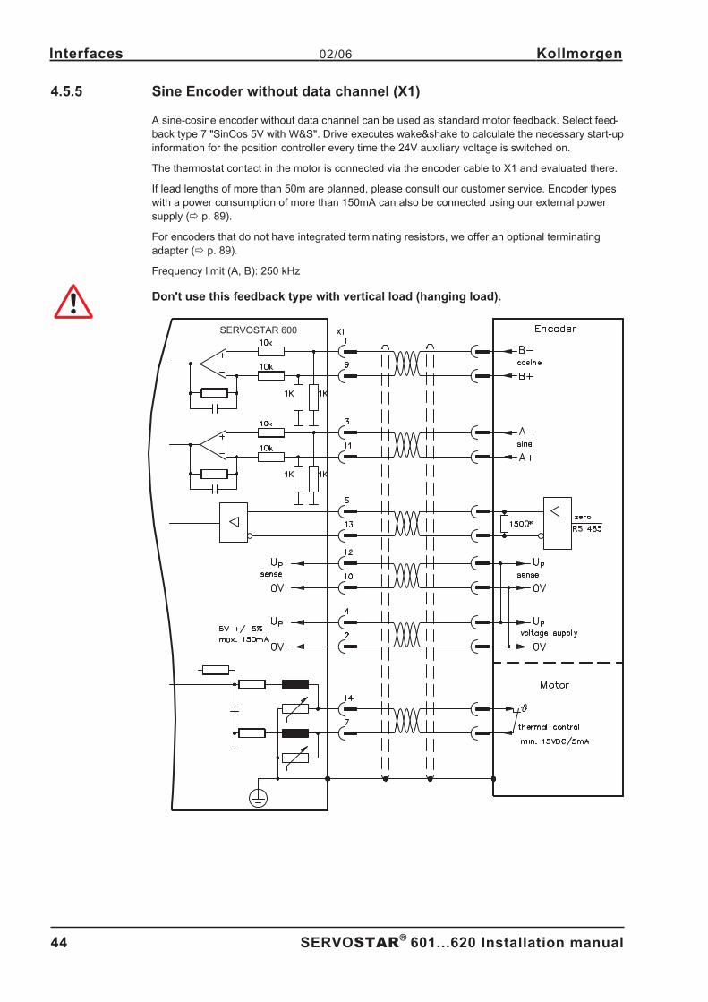
4.5.5 Sine Encoder without data channel (X1) . . . . . . . . . . . . . . . . . . . . . . . . . . . . . . . . . . . . . . . . . . . . . . . . . . . . . . . . . . . 44
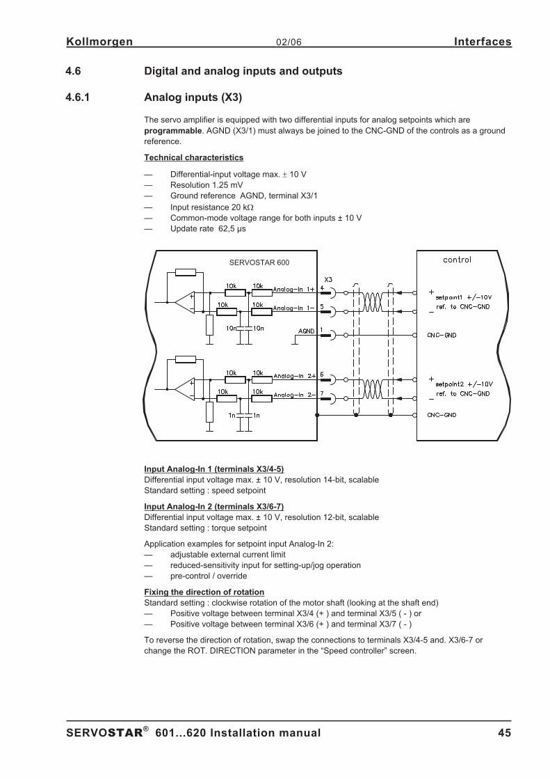
4.6 Digital and analog inputs and outputs. . . . . . . . . . . . . . . . . . . . . . . . . . . . . . . . . . . . . . . . . . . . . . . . . . . . . . . . . . . . . . . . . . . 45
4.6.1 Analog inputs (X3). . . . . . . . . . . . . . . . . . . . . . . . . . . . . . . . . . . . . . . . . . . . . . . . . . . . . . . . . . . . . . . . . . . . . . . . . . . . 45
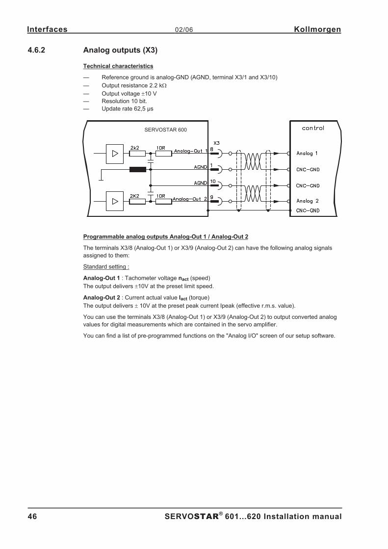
4.6.2 Analog outputs (X3). . . . . . . . . . . . . . . . . . . . . . . . . . . . . . . . . . . . . . . . . . . . . . . . . . . . . . . . . . . . . . . . . . . . . . . . . . . 46
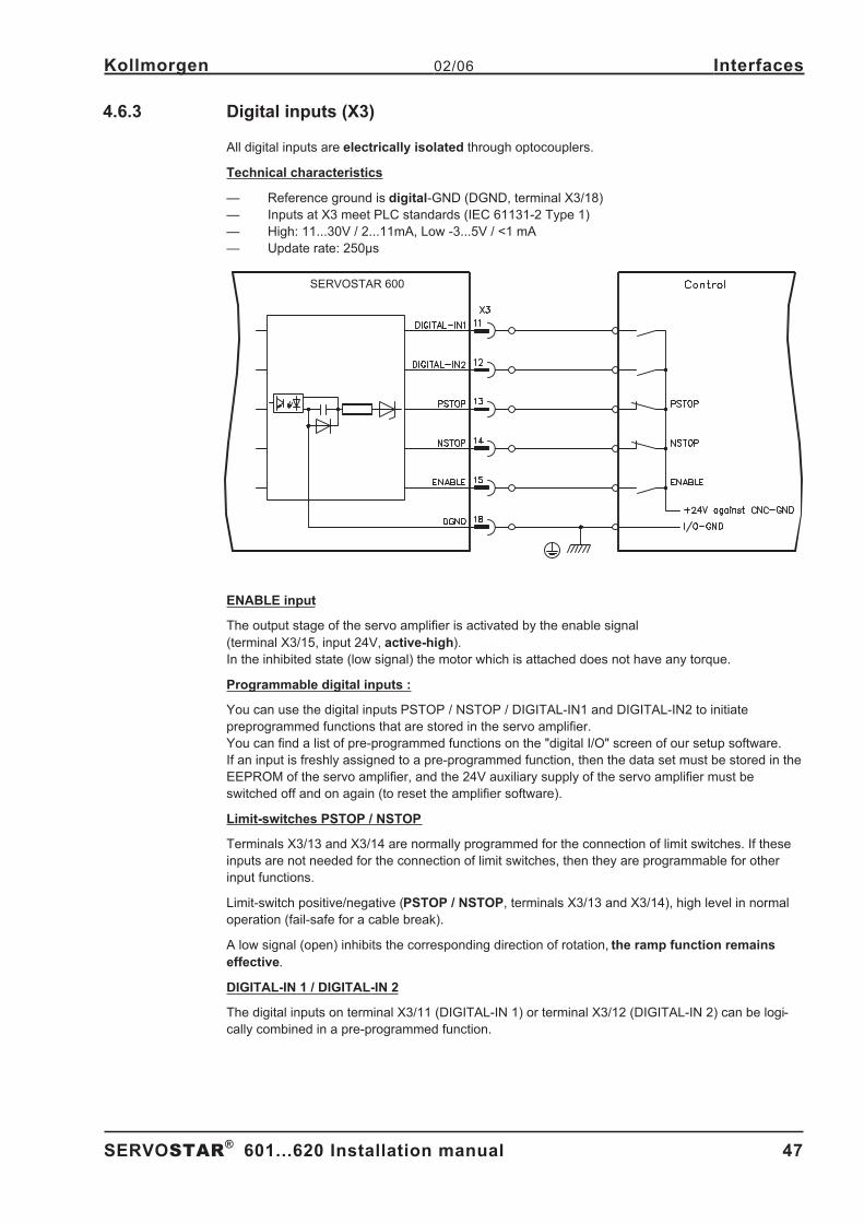
4.6.3 Digital inputs (X3) . . . . . . . . . . . . . . . . . . . . . . . . . . . . . . . . . . . . . . . . . . . . . . . . . . . . . . . . . . . . . . . . . . . . . . . . . . . . 47
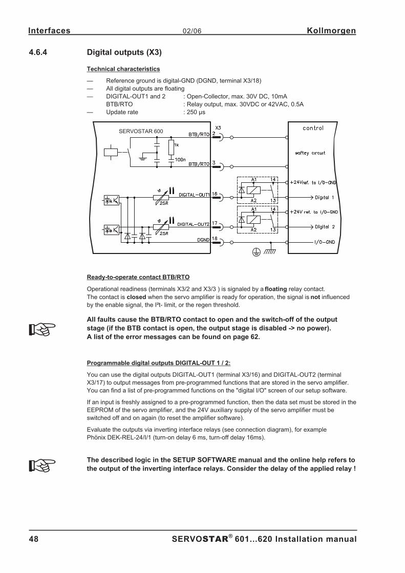
4.6.4 Digital outputs (X3) . . . . . . . . . . . . . . . . . . . . . . . . . . . . . . . . . . . . . . . . . . . . . . . . . . . . . . . . . . . . . . . . . . . . . . . . . . . 48
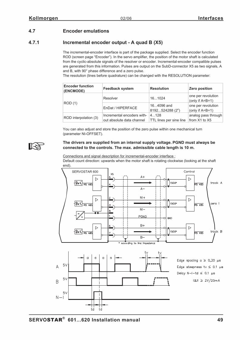
4.7 Encoder emulations . . . . . . . . . . . . . . . . . . . . . . . . . . . . . . . . . . . . . . . . . . . . . . . . . . . . . . . . . . . . . . . . . . . . . . . . . . . . . . . . 49
4.7.1 Incremental encoder output - A quad B (X5) . . . . . . . . . . . . . . . . . . . . . . . . . . . . . . . . . . . . . . . . . . . . . . . . . . . . . . . . 49
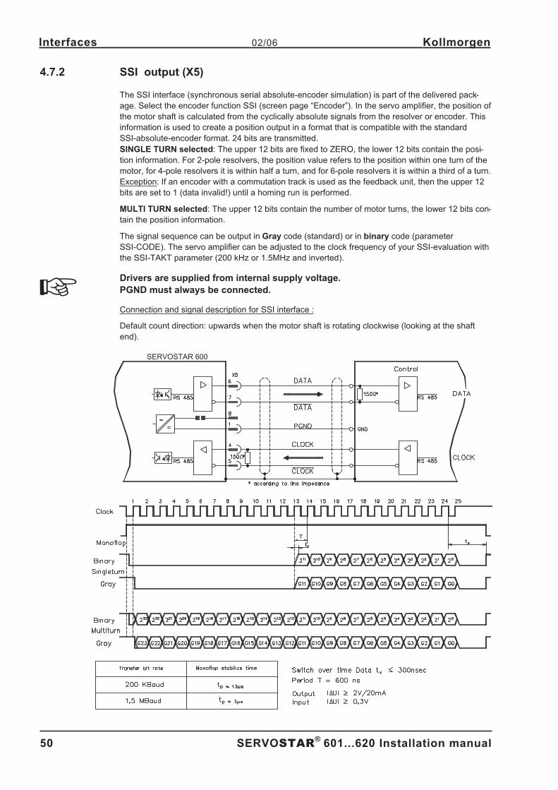
4.7.2 SSI output (X5). . . . . . . . . . . . . . . . . . . . . . . . . . . . . . . . . . . . . . . . . . . . . . . . . . . . . . . . . . . . . . . . . . . . . . . . . . . . . . 50
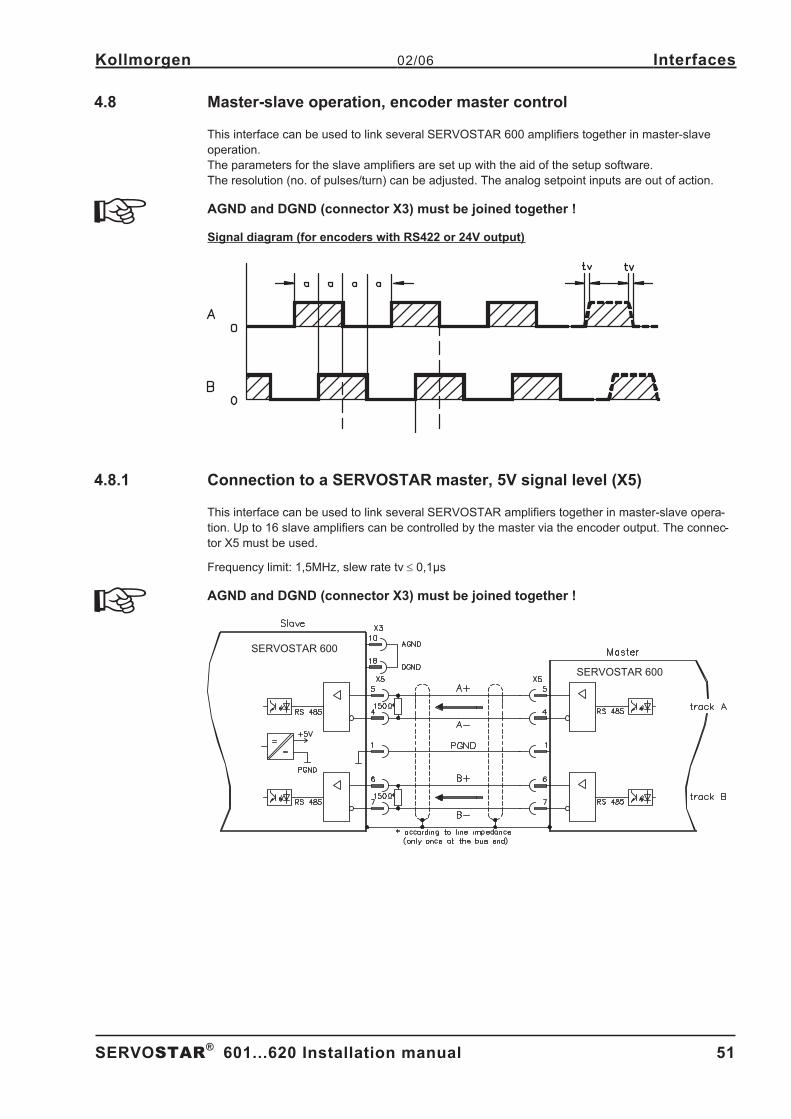
4.8 Master-slave operation, encoder master control . . . . . . . . . . . . . . . . . . . . . . . . . . . . . . . . . . . . . . . . . . . . . . . . . . . . . . . . . . 51
4.8.1 Connection to a SERVOSTAR master, 5V signal level (X5) . . . . . . . . . . . . . . . . . . . . . . . . . . . . . . . . . . . . . . . . . . . . 51
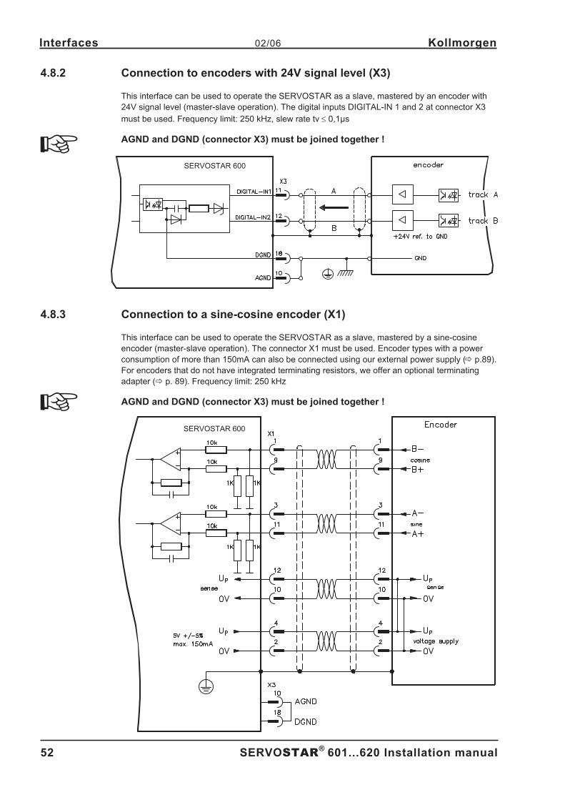
4.8.2 Connection to encoders with 24V signal level (X3) . . . . . . . . . . . . . . . . . . . . . . . . . . . . . . . . . . . . . . . . . . . . . . . . . . . 52
4.8.3 Connection to a sine-cosine encoder (X1) . . . . . . . . . . . . . . . . . . . . . . . . . . . . . . . . . . . . . . . . . . . . . . . . . . . . . . . . . 52
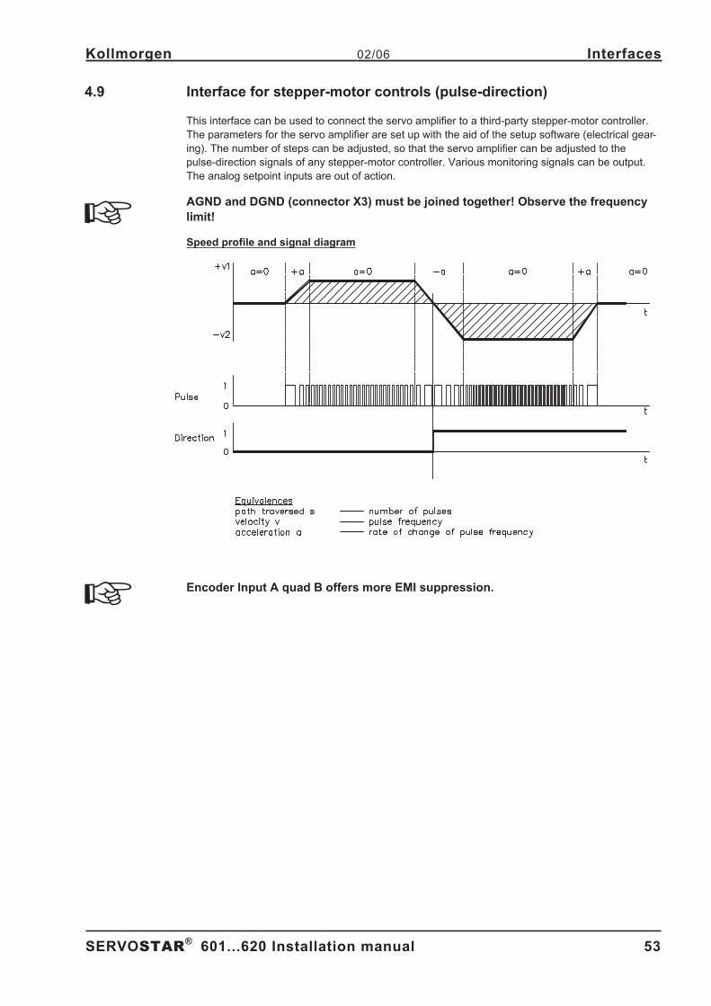
4.9 Interface for stepper-motor controls (pulse-direction) . . . . . . . . . . . . . . . . . . . . . . . . . . . . . . . . . . . . . . . . . . . . . . . . . . . . . . . 53
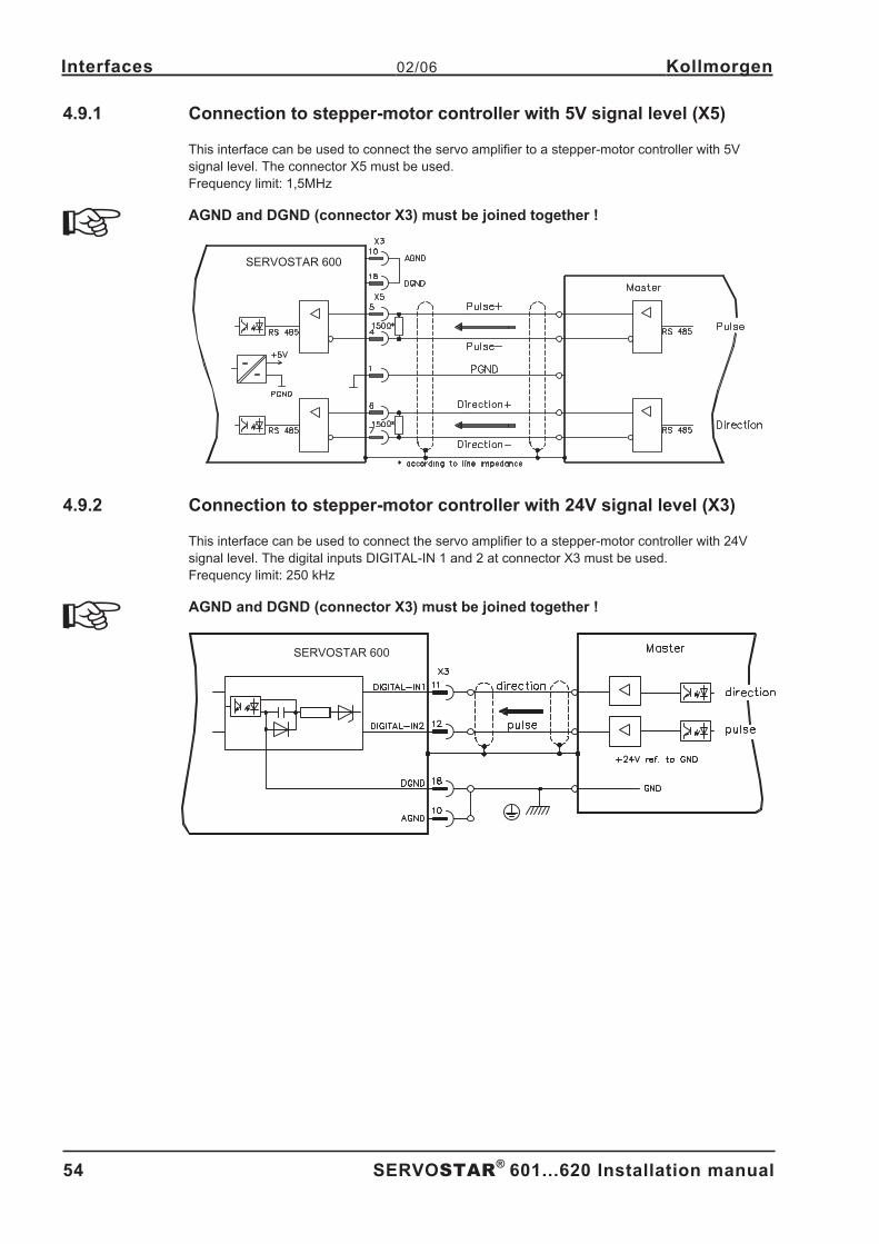
4.9.1 Connection to stepper-motor controller with 5V signal level (X5) . . . . . . . . . . . . . . . . . . . . . . . . . . . . . . . . . . . . . . . . 54
4.9.2 Connection to stepper-motor controller with 24V signal level (X3) . . . . . . . . . . . . . . . . . . . . . . . . . . . . . . . . . . . . . . . 54
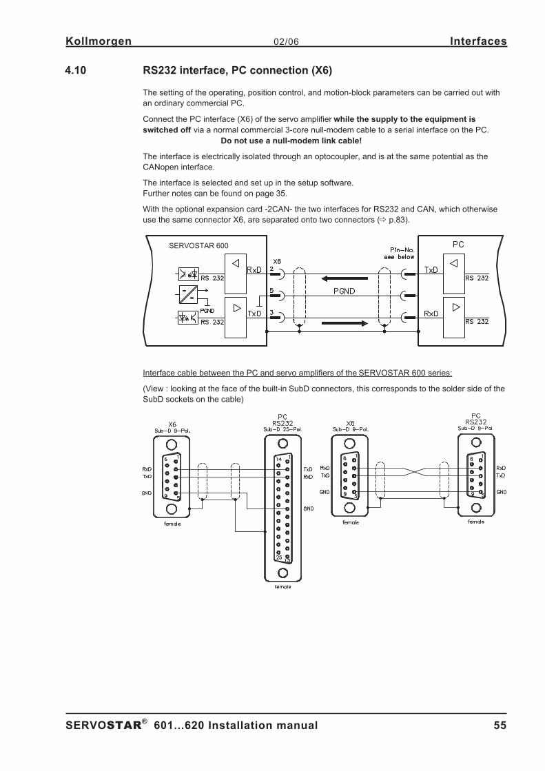
4.10 RS232 interface, PC connection (X6) . . . . . . . . . . . . . . . . . . . . . . . . . . . . . . . . . . . . . . . . . . . . . . . . . . . . . . . . . . . . . . . . . . . 55
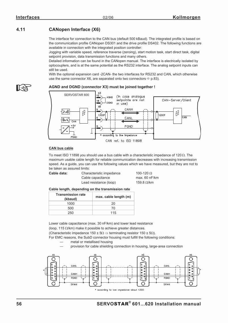
4.11 CANopen Interface (X6) . . . . . . . . . . . . . . . . . . . . . . . . . . . . . . . . . . . . . . . . . . . . . . . . . . . . . . . . . . . . . . . . . . . . . . . . . . . . . 56
5 Setup5.1 Important notes . . . . . . . . . . . . . . . . . . . . . . . . . . . . . . . . . . . . . . . . . . . . . . . . . . . . . . . . . . . . . . . . . . . . . . . . . . . . . . . . . . . . 57
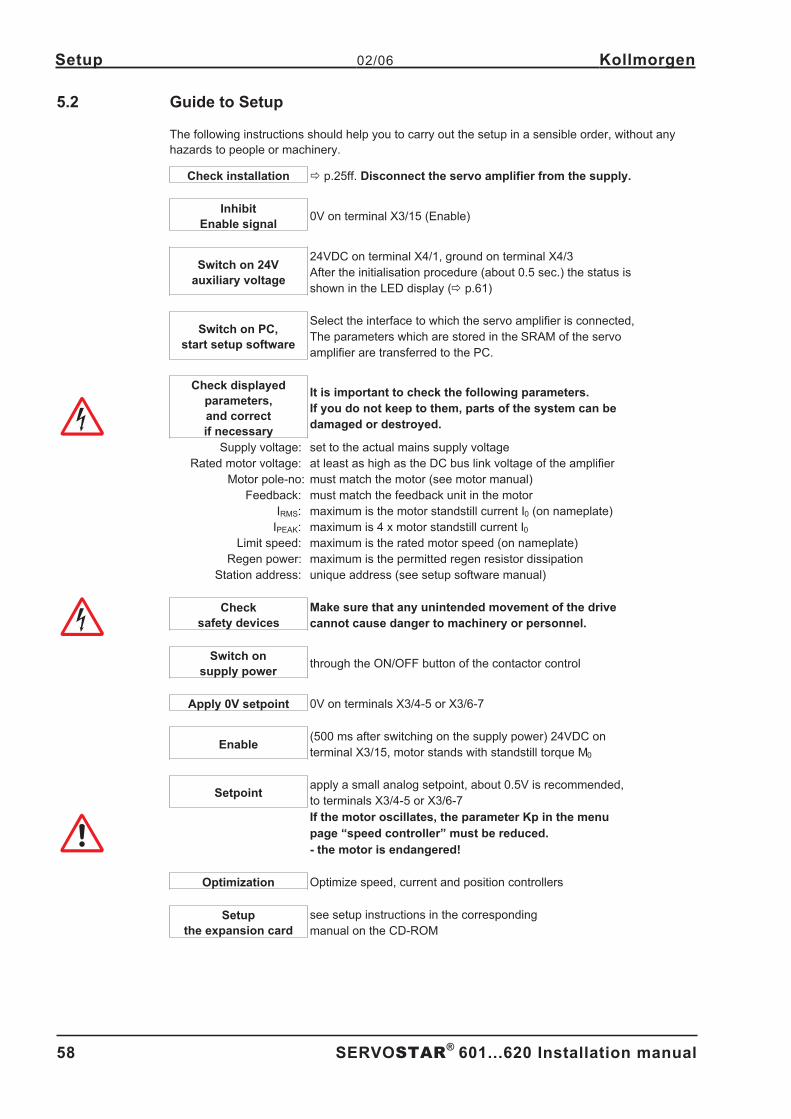
5.2 Guide to Setup . . . . . . . . . . . . . . . . . . . . . . . . . . . . . . . . . . . . . . . . . . . . . . . . . . . . . . . . . . . . . . . . . . . . . . . . . . . . . . . . . . . . 58
5.3 Parameter setting . . . . . . . . . . . . . . . . . . . . . . . . . . . . . . . . . . . . . . . . . . . . . . . . . . . . . . . . . . . . . . . . . . . . . . . . . . . . . . . . . . 59
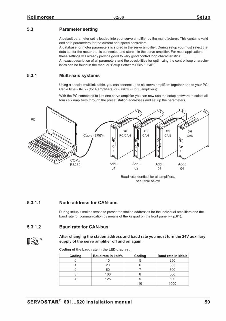
5.3.1 Multi-axis systems . . . . . . . . . . . . . . . . . . . . . . . . . . . . . . . . . . . . . . . . . . . . . . . . . . . . . . . . . . . . . . . . . . . . . . . . . . . . 59
5.3.1.1 Node address for CAN-bus . . . . . . . . . . . . . . . . . . . . . . . . . . . . . . . . . . . . . . . . . . . . . . . . . . . . . . . . . . . . . . . . . 59
5.3.1.2 Baud rate for CAN-bus . . . . . . . . . . . . . . . . . . . . . . . . . . . . . . . . . . . . . . . . . . . . . . . . . . . . . . . . . . . . . . . . . . . . 59
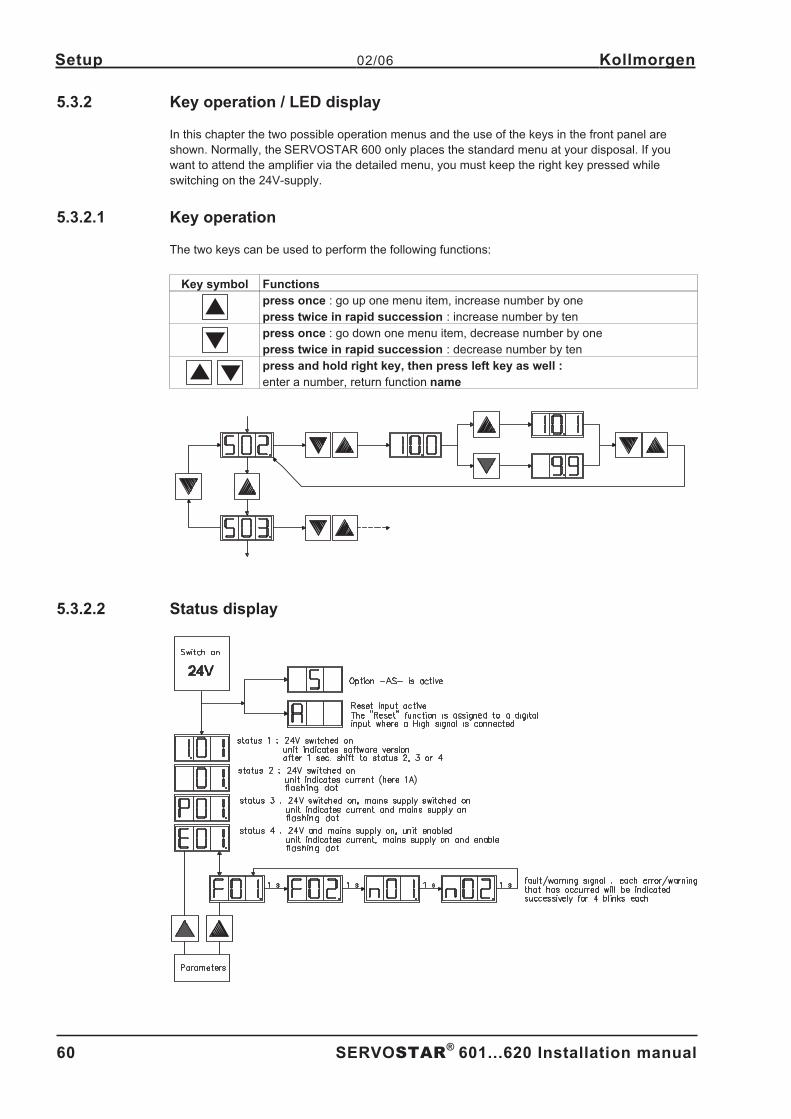
5.3.2 Key operation / LED display . . . . . . . . . . . . . . . . . . . . . . . . . . . . . . . . . . . . . . . . . . . . . . . . . . . . . . . . . . . . . . . . . . . . 60
5.3.2.1 Key operation. . . . . . . . . . . . . . . . . . . . . . . . . . . . . . . . . . . . . . . . . . . . . . . . . . . . . . . . . . . . . . . . . . . . . . . . . . . . 60
5.3.2.2 Status display . . . . . . . . . . . . . . . . . . . . . . . . . . . . . . . . . . . . . . . . . . . . . . . . . . . . . . . . . . . . . . . . . . . . . . . . . . . 60
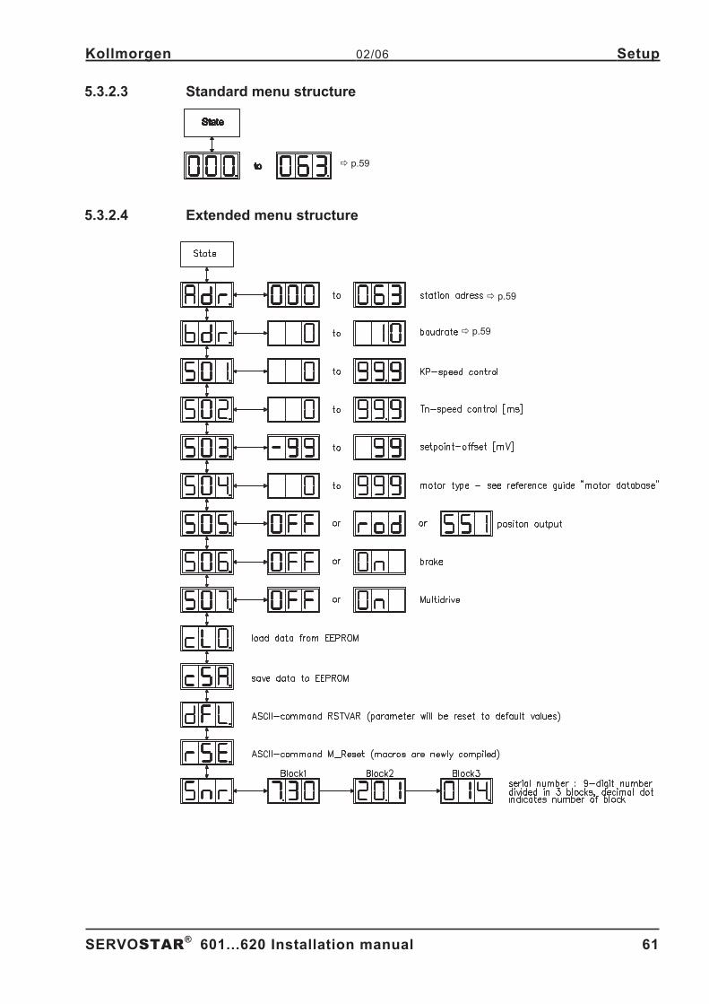
5.3.2.3 Standard menu structure . . . . . . . . . . . . . . . . . . . . . . . . . . . . . . . . . . . . . . . . . . . . . . . . . . . . . . . . . . . . . . . . . . . 61
5.3.2.4 Extended menu structure. . . . . . . . . . . . . . . . . . . . . . . . . . . . . . . . . . . . . . . . . . . . . . . . . . . . . . . . . . . . . . . . . . . 61
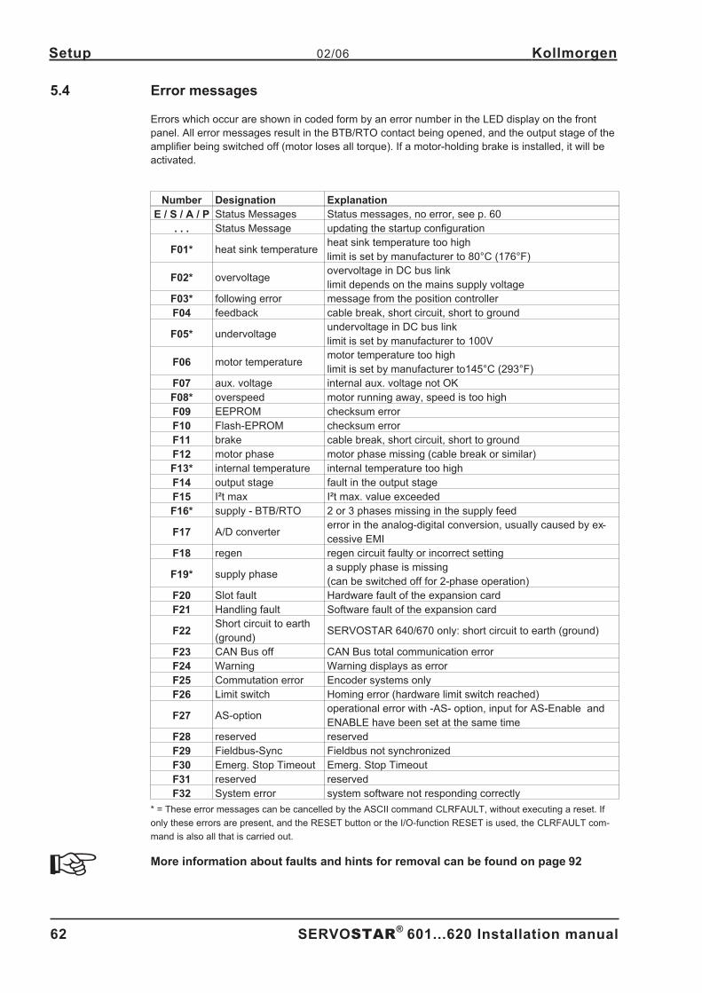
5.4 Error messages . . . . . . . . . . . . . . . . . . . . . . . . . . . . . . . . . . . . . . . . . . . . . . . . . . . . . . . . . . . . . . . . . . . . . . . . . . . . . . . . . . . 62
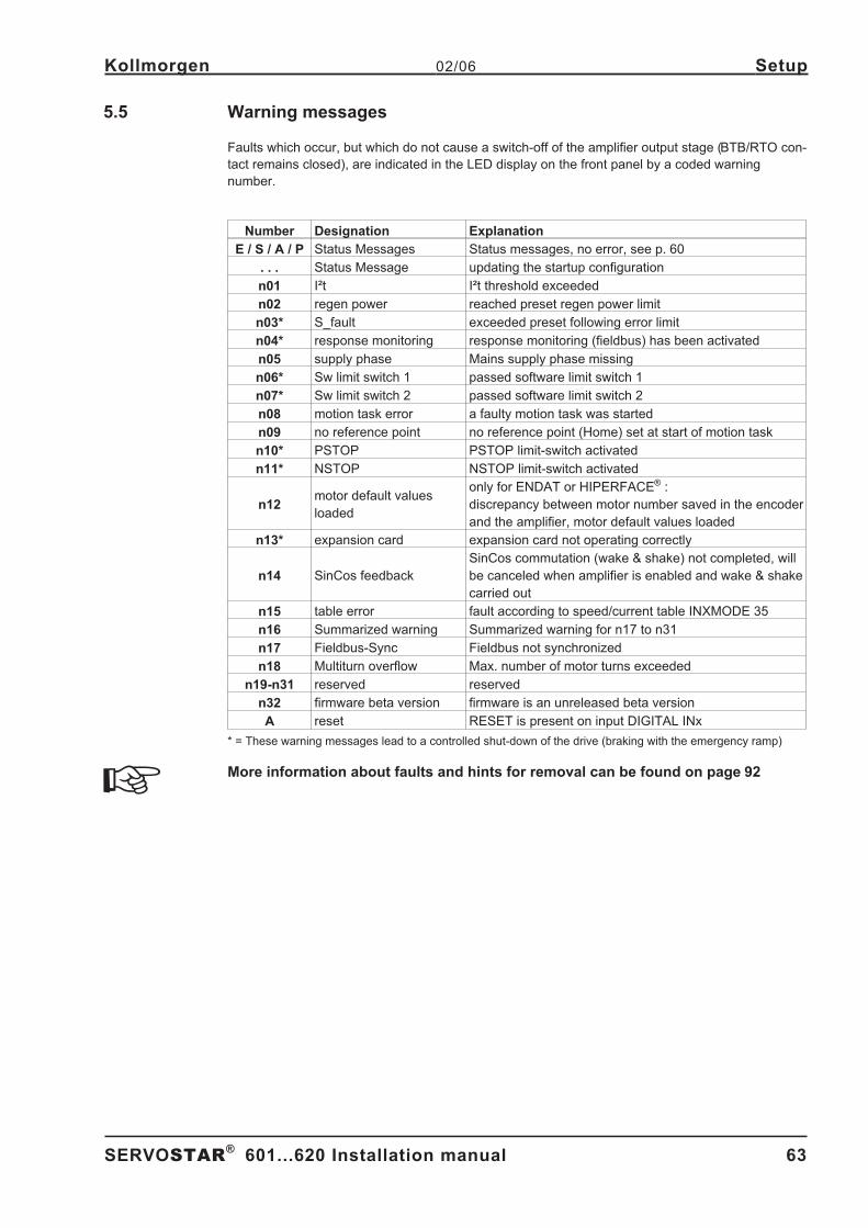
5.5 Warning messages . . . . . . . . . . . . . . . . . . . . . . . . . . . . . . . . . . . . . . . . . . . . . . . . . . . . . . . . . . . . . . . . . . . . . . . . . . . . . . . . . 63
6 Expansions / Accessories6.1 Option -AS-, restart lock for personal safety . . . . . . . . . . . . . . . . . . . . . . . . . . . . . . . . . . . . . . . . . . . . . . . . . . . . . . . . . . . . . . 65
6.1.1 Advantages of the -AS- option . . . . . . . . . . . . . . . . . . . . . . . . . . . . . . . . . . . . . . . . . . . . . . . . . . . . . . . . . . . . . . . . . . 65
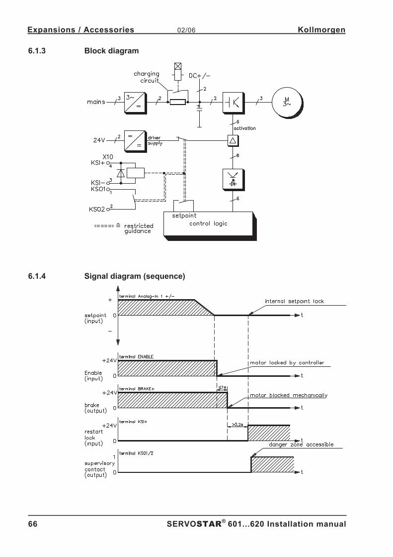
6.1.2 Functional description . . . . . . . . . . . . . . . . . . . . . . . . . . . . . . . . . . . . . . . . . . . . . . . . . . . . . . . . . . . . . . . . . . . . . . . . . 65
6.1.3 Block diagram . . . . . . . . . . . . . . . . . . . . . . . . . . . . . . . . . . . . . . . . . . . . . . . . . . . . . . . . . . . . . . . . . . . . . . . . . . . . . . . 66
6.1.4 Signal diagram (sequence) . . . . . . . . . . . . . . . . . . . . . . . . . . . . . . . . . . . . . . . . . . . . . . . . . . . . . . . . . . . . . . . . . . . . . 66
6.1.5 Installation / Setup. . . . . . . . . . . . . . . . . . . . . . . . . . . . . . . . . . . . . . . . . . . . . . . . . . . . . . . . . . . . . . . . . . . . . . . . . . . . 67
6.1.5.1 Safety instructions . . . . . . . . . . . . . . . . . . . . . . . . . . . . . . . . . . . . . . . . . . . . . . . . . . . . . . . . . . . . . . . . . . . . . . . . 67
6.1.5.2 Functional test . . . . . . . . . . . . . . . . . . . . . . . . . . . . . . . . . . . . . . . . . . . . . . . . . . . . . . . . . . . . . . . . . . . . . . . . . . . 67
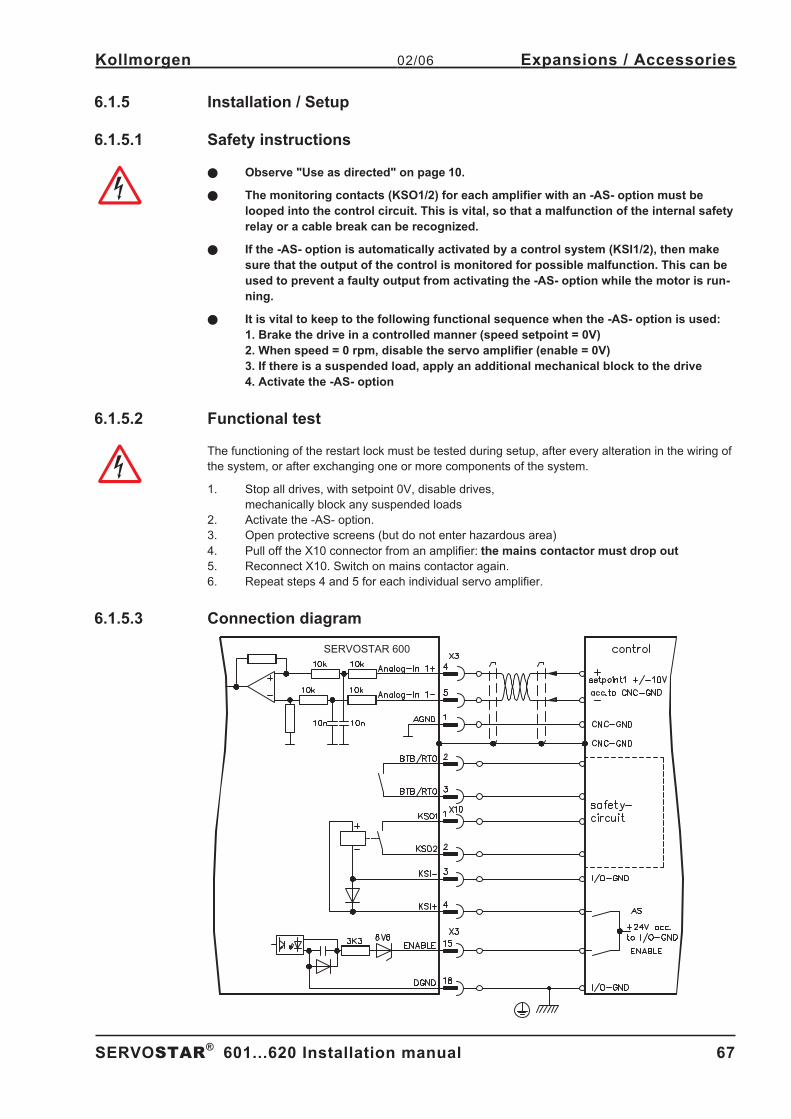
6.1.5.3 Connection diagram. . . . . . . . . . . . . . . . . . . . . . . . . . . . . . . . . . . . . . . . . . . . . . . . . . . . . . . . . . . . . . . . . . . . . . . 67
6.1.6 Application examples . . . . . . . . . . . . . . . . . . . . . . . . . . . . . . . . . . . . . . . . . . . . . . . . . . . . . . . . . . . . . . . . . . . . . . . . . 68
6.1.6.1 Moving single axes or axis-groups in setting-up operation . . . . . . . . . . . . . . . . . . . . . . . . . . . . . . . . . . . . . . . . . 68
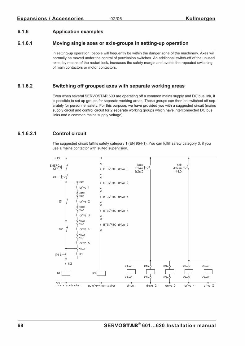
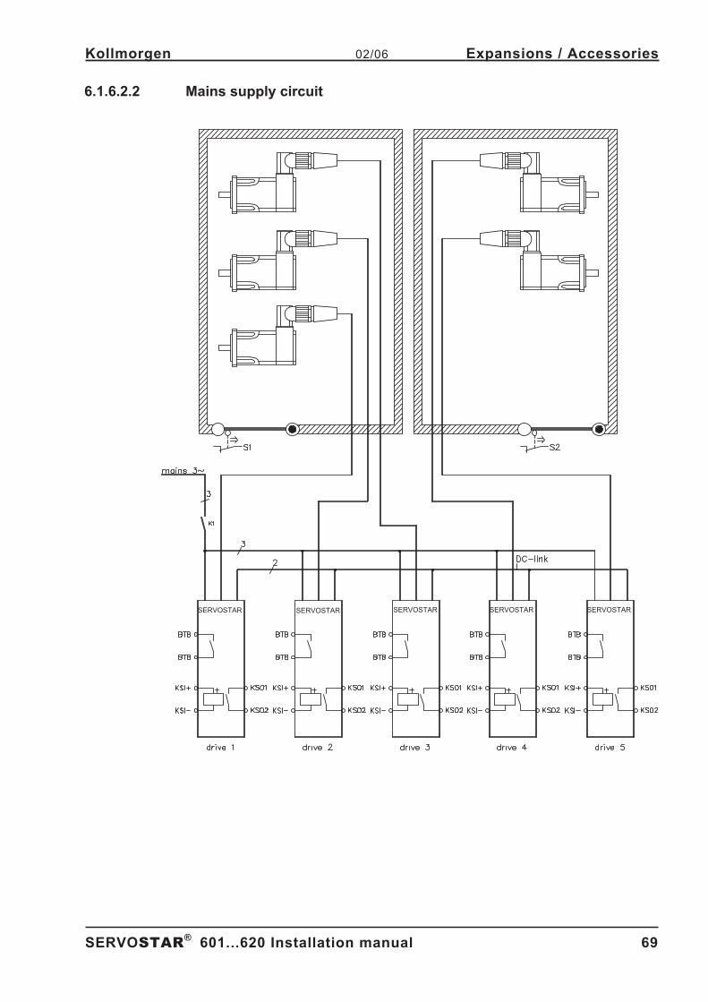
6.1.6.2 Switching off grouped axes with separate working areas . . . . . . . . . . . . . . . . . . . . . . . . . . . . . . . . . . . . . . . . . . 68
6.1.6.2.1 Control circuit. . . . . . . . . . . . . . . . . . . . . . . . . . . . . . . . . . . . . . . . . . . . . . . . . . . . . . . . . . . . . . . . . . . . . . . 68
6.1.6.2.2 Mains supply circuit . . . . . . . . . . . . . . . . . . . . . . . . . . . . . . . . . . . . . . . . . . . . . . . . . . . . . . . . . . . . . . . . . . 69
4 SERVOSTAR®
601...620 Installation manual
Contents 02/06 Kollmorgen
Page
Page 5
6.2 Expansion Cards . . . . . . . . . . . . . . . . . . . . . . . . . . . . . . . . . . . . . . . . . . . . . . . . . . . . . . . . . . . . . . . . . . . . . . . . . . . . . . . . . . 70
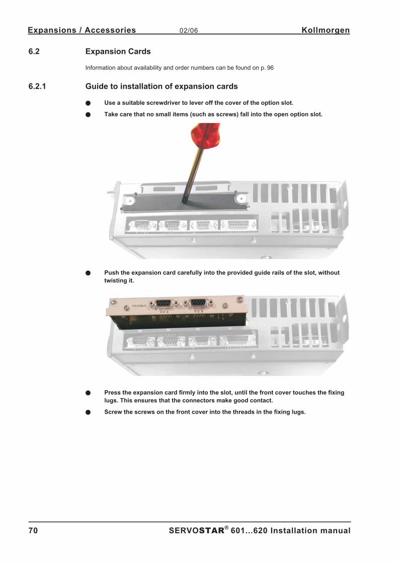
6.2.1 Guide to installation of expansion cards . . . . . . . . . . . . . . . . . . . . . . . . . . . . . . . . . . . . . . . . . . . . . . . . . . . . . . . . . . . 70
6.2.2 Expansion card -I/O-14/08- . . . . . . . . . . . . . . . . . . . . . . . . . . . . . . . . . . . . . . . . . . . . . . . . . . . . . . . . . . . . . . . . . . . . . 71
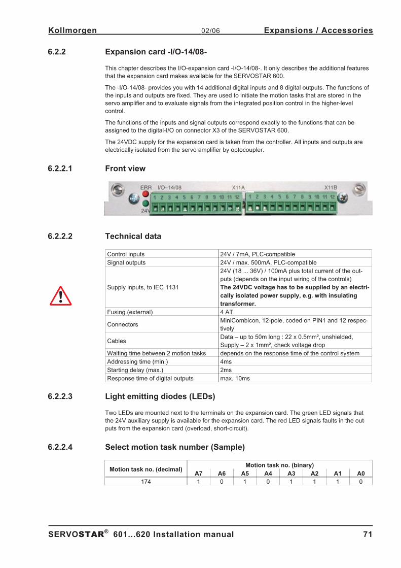
6.2.2.1 Front view . . . . . . . . . . . . . . . . . . . . . . . . . . . . . . . . . . . . . . . . . . . . . . . . . . . . . . . . . . . . . . . . . . . . . . . . . . . . . . 71
6.2.2.2 Technical data . . . . . . . . . . . . . . . . . . . . . . . . . . . . . . . . . . . . . . . . . . . . . . . . . . . . . . . . . . . . . . . . . . . . . . . . . . . 71
6.2.2.3 Light emitting diodes (LEDs) . . . . . . . . . . . . . . . . . . . . . . . . . . . . . . . . . . . . . . . . . . . . . . . . . . . . . . . . . . . . . . . . 71
6.2.2.4 Select motion task number (Sample). . . . . . . . . . . . . . . . . . . . . . . . . . . . . . . . . . . . . . . . . . . . . . . . . . . . . . . . . . 71
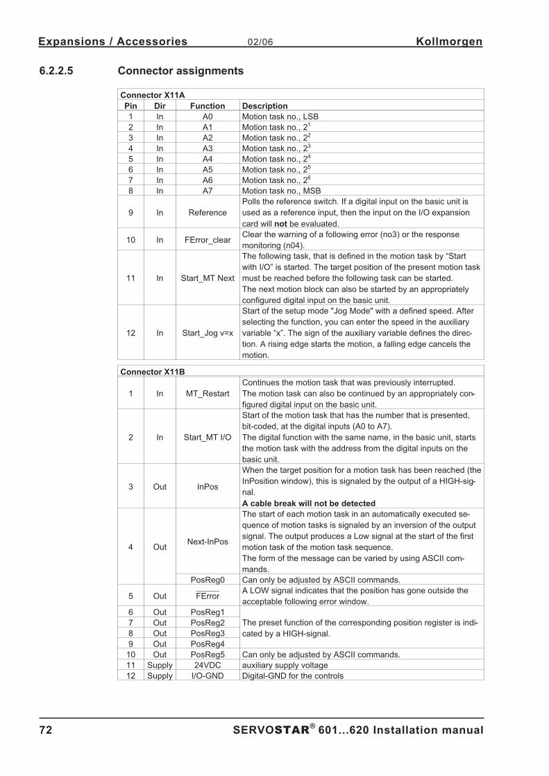
6.2.2.5 Connector assignments . . . . . . . . . . . . . . . . . . . . . . . . . . . . . . . . . . . . . . . . . . . . . . . . . . . . . . . . . . . . . . . . . . . . 72
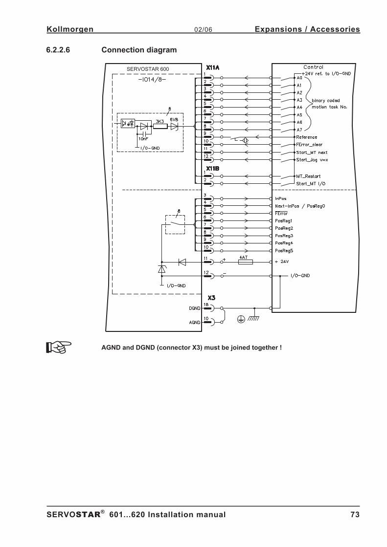
6.2.2.6 Connection diagram. . . . . . . . . . . . . . . . . . . . . . . . . . . . . . . . . . . . . . . . . . . . . . . . . . . . . . . . . . . . . . . . . . . . . . . 73
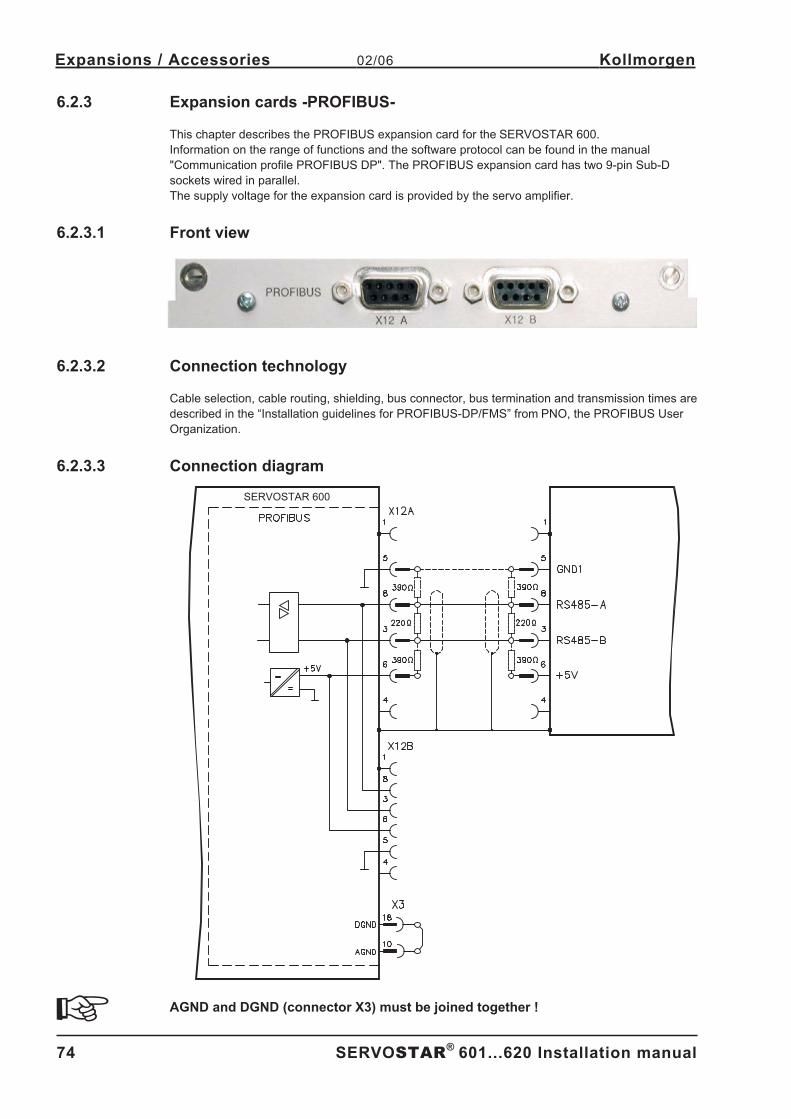
6.2.3 Expansion cards -PROFIBUS- . . . . . . . . . . . . . . . . . . . . . . . . . . . . . . . . . . . . . . . . . . . . . . . . . . . . . . . . . . . . . . . . . . 74
6.2.3.1 Front view . . . . . . . . . . . . . . . . . . . . . . . . . . . . . . . . . . . . . . . . . . . . . . . . . . . . . . . . . . . . . . . . . . . . . . . . . . . . . . 74
6.2.3.2 Connection technology . . . . . . . . . . . . . . . . . . . . . . . . . . . . . . . . . . . . . . . . . . . . . . . . . . . . . . . . . . . . . . . . . . . . 74
6.2.3.3 Connection diagram. . . . . . . . . . . . . . . . . . . . . . . . . . . . . . . . . . . . . . . . . . . . . . . . . . . . . . . . . . . . . . . . . . . . . . . 74
6.2.4 Expansion card -SERCOS- . . . . . . . . . . . . . . . . . . . . . . . . . . . . . . . . . . . . . . . . . . . . . . . . . . . . . . . . . . . . . . . . . . . . . 75
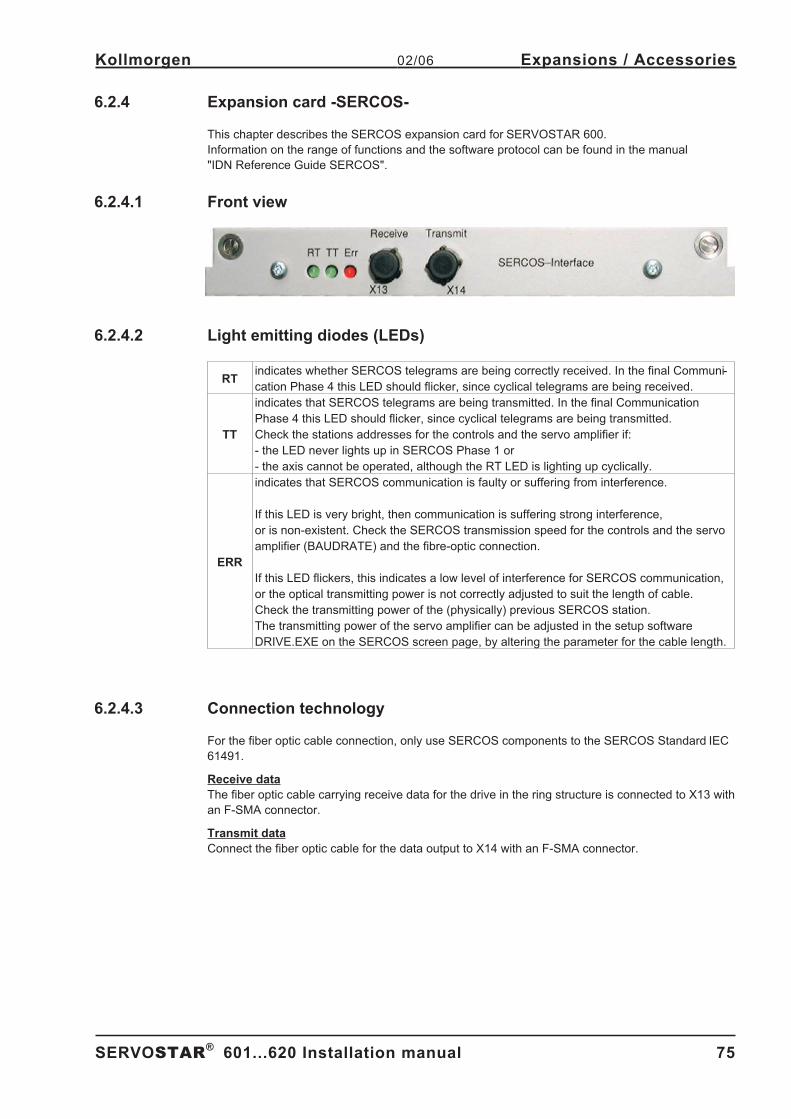
6.2.4.1 Front view . . . . . . . . . . . . . . . . . . . . . . . . . . . . . . . . . . . . . . . . . . . . . . . . . . . . . . . . . . . . . . . . . . . . . . . . . . . . . . 75
6.2.4.2 Light emitting diodes (LEDs) . . . . . . . . . . . . . . . . . . . . . . . . . . . . . . . . . . . . . . . . . . . . . . . . . . . . . . . . . . . . . . . . 75
6.2.4.3 Connection technology . . . . . . . . . . . . . . . . . . . . . . . . . . . . . . . . . . . . . . . . . . . . . . . . . . . . . . . . . . . . . . . . . . . . 75
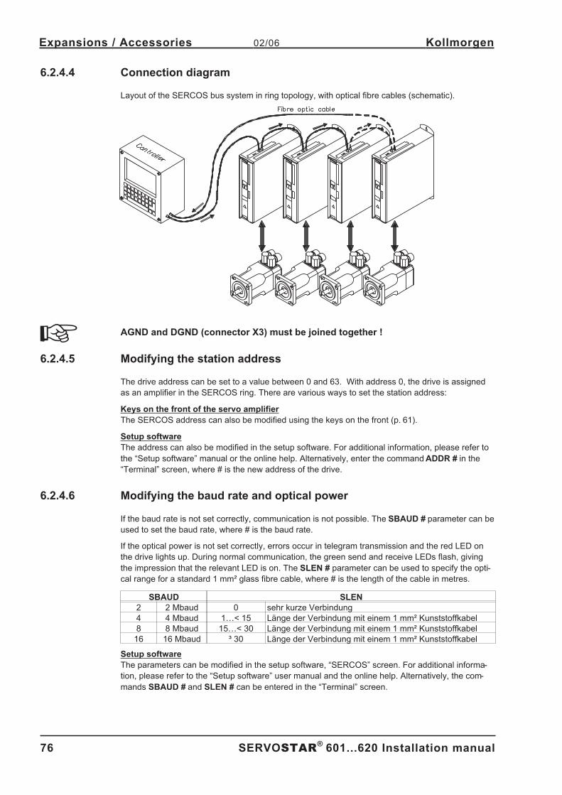
6.2.4.4 Connection diagram. . . . . . . . . . . . . . . . . . . . . . . . . . . . . . . . . . . . . . . . . . . . . . . . . . . . . . . . . . . . . . . . . . . . . . . 76
6.2.4.5 Modifying the station address . . . . . . . . . . . . . . . . . . . . . . . . . . . . . . . . . . . . . . . . . . . . . . . . . . . . . . . . . . . . . . . 76
6.2.4.6 Modifying the baud rate and optical power . . . . . . . . . . . . . . . . . . . . . . . . . . . . . . . . . . . . . . . . . . . . . . . . . . . . . 76
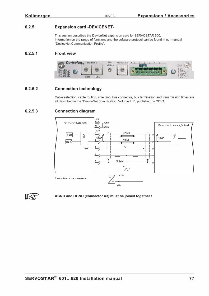
6.2.5 Expansion card -DEVICENET- . . . . . . . . . . . . . . . . . . . . . . . . . . . . . . . . . . . . . . . . . . . . . . . . . . . . . . . . . . . . . . . . . . 77
6.2.5.1 Front view . . . . . . . . . . . . . . . . . . . . . . . . . . . . . . . . . . . . . . . . . . . . . . . . . . . . . . . . . . . . . . . . . . . . . . . . . . . . . . 77
6.2.5.2 Connection technology . . . . . . . . . . . . . . . . . . . . . . . . . . . . . . . . . . . . . . . . . . . . . . . . . . . . . . . . . . . . . . . . . . . . 77
6.2.5.3 Connection diagram. . . . . . . . . . . . . . . . . . . . . . . . . . . . . . . . . . . . . . . . . . . . . . . . . . . . . . . . . . . . . . . . . . . . . . . 77
6.2.5.4 Combined module/network status-LED . . . . . . . . . . . . . . . . . . . . . . . . . . . . . . . . . . . . . . . . . . . . . . . . . . . . . . . . 78
6.2.5.5 Setting the station address (device address). . . . . . . . . . . . . . . . . . . . . . . . . . . . . . . . . . . . . . . . . . . . . . . . . . . . 78
6.2.5.6 Setting the transmission speed . . . . . . . . . . . . . . . . . . . . . . . . . . . . . . . . . . . . . . . . . . . . . . . . . . . . . . . . . . . . . . 78
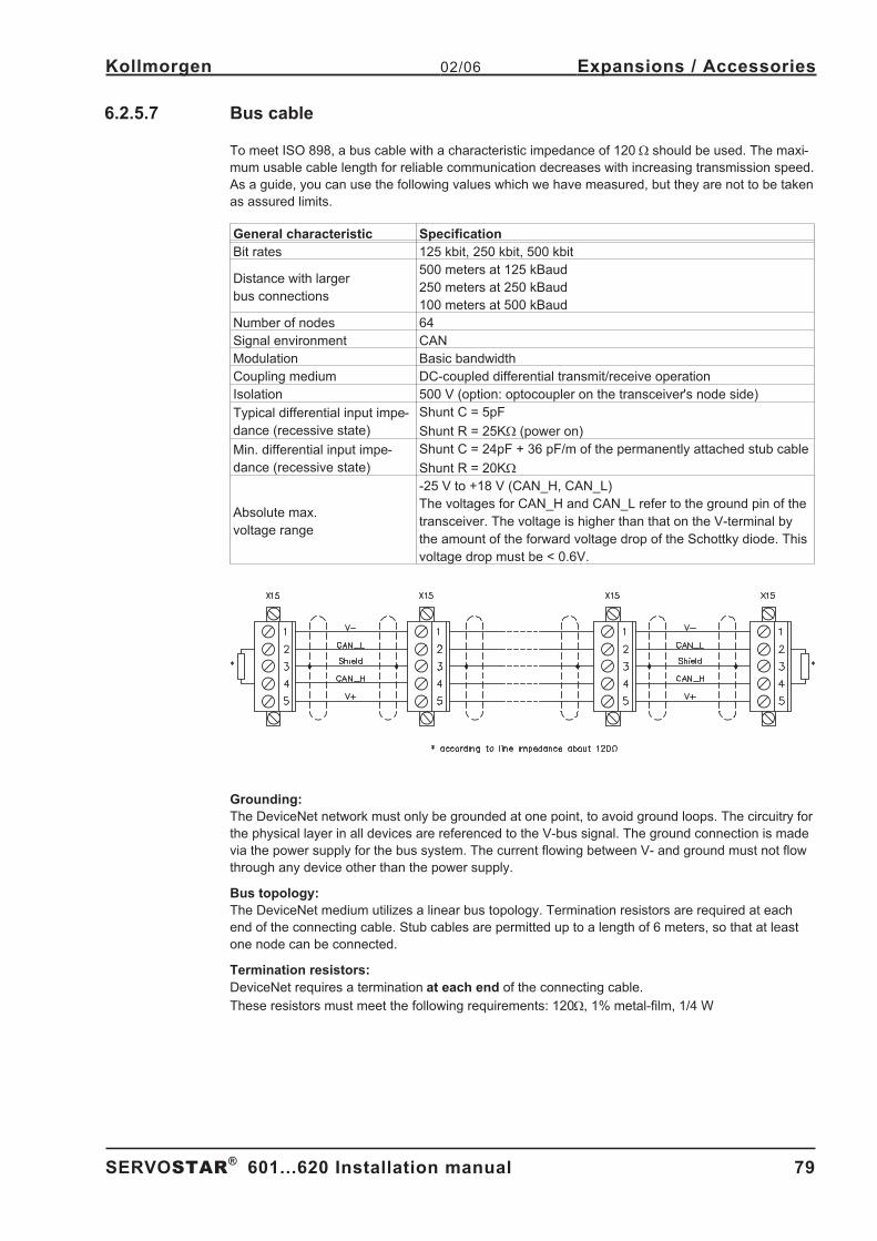
6.2.5.7 Bus cable . . . . . . . . . . . . . . . . . . . . . . . . . . . . . . . . . . . . . . . . . . . . . . . . . . . . . . . . . . . . . . . . . . . . . . . . . . . . . . . 79
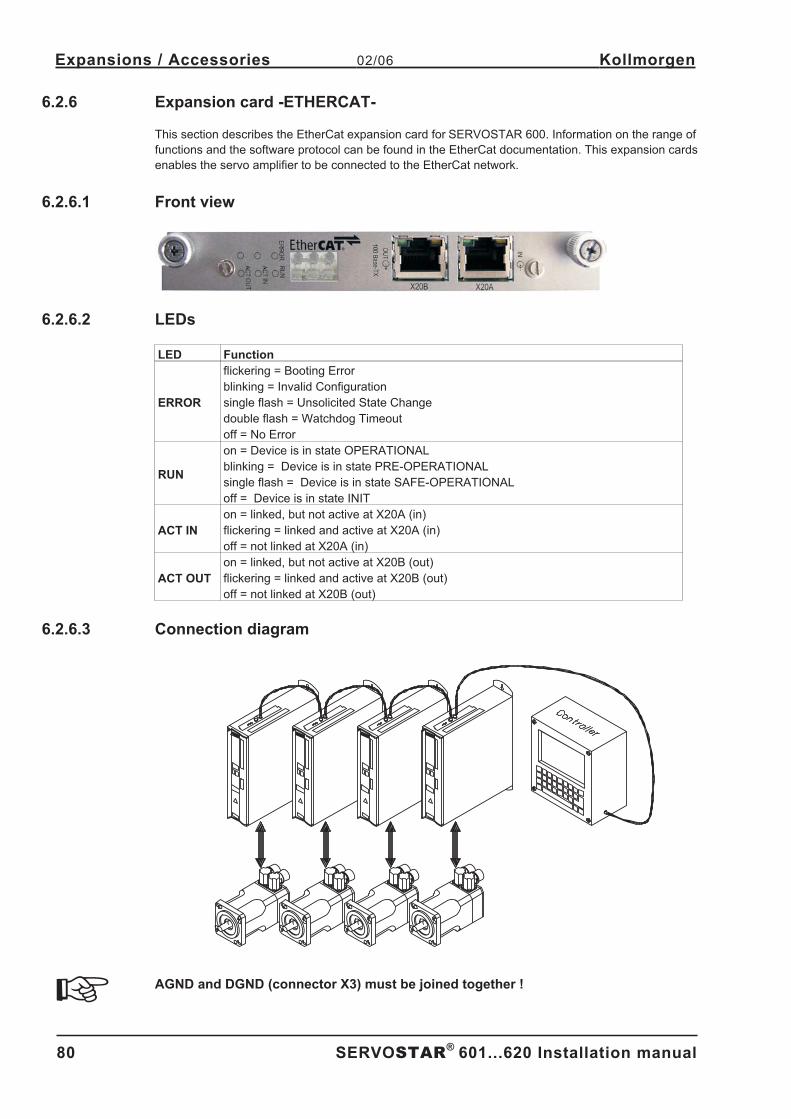
6.2.6 Expansion card -ETHERCAT-. . . . . . . . . . . . . . . . . . . . . . . . . . . . . . . . . . . . . . . . . . . . . . . . . . . . . . . . . . . . . . . . . . . 80
6.2.6.1 Front view . . . . . . . . . . . . . . . . . . . . . . . . . . . . . . . . . . . . . . . . . . . . . . . . . . . . . . . . . . . . . . . . . . . . . . . . . . . . . . 80
6.2.6.2 LEDs . . . . . . . . . . . . . . . . . . . . . . . . . . . . . . . . . . . . . . . . . . . . . . . . . . . . . . . . . . . . . . . . . . . . . . . . . . . . . . . . . . 80
6.2.6.3 Connection diagram. . . . . . . . . . . . . . . . . . . . . . . . . . . . . . . . . . . . . . . . . . . . . . . . . . . . . . . . . . . . . . . . . . . . . . . 80
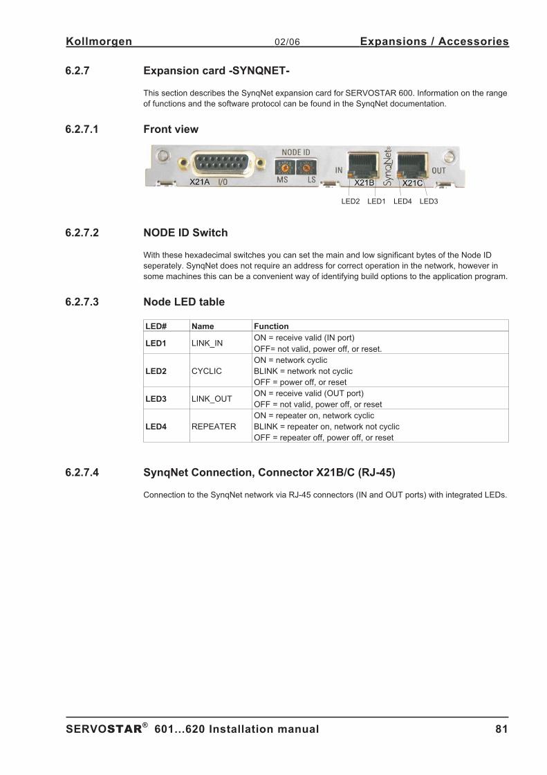
6.2.7 Expansion card -SYNQNET-. . . . . . . . . . . . . . . . . . . . . . . . . . . . . . . . . . . . . . . . . . . . . . . . . . . . . . . . . . . . . . . . . . . . 81
6.2.7.1 Front view . . . . . . . . . . . . . . . . . . . . . . . . . . . . . . . . . . . . . . . . . . . . . . . . . . . . . . . . . . . . . . . . . . . . . . . . . . . . . . 81
6.2.7.2 NODE ID Switch . . . . . . . . . . . . . . . . . . . . . . . . . . . . . . . . . . . . . . . . . . . . . . . . . . . . . . . . . . . . . . . . . . . . . . . . . 81
6.2.7.3 Node LED table . . . . . . . . . . . . . . . . . . . . . . . . . . . . . . . . . . . . . . . . . . . . . . . . . . . . . . . . . . . . . . . . . . . . . . . . . 81
6.2.7.4 SynqNet Connection, Connector X21B/C (RJ-45) . . . . . . . . . . . . . . . . . . . . . . . . . . . . . . . . . . . . . . . . . . . . . . . . 81
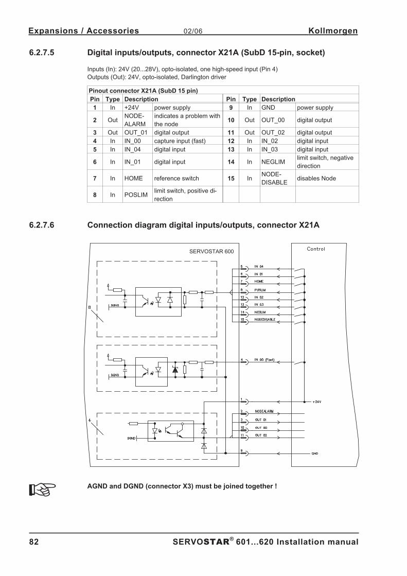
6.2.7.5 Digital inputs/outputs, connector X21A (SubD 15-pin, socket) . . . . . . . . . . . . . . . . . . . . . . . . . . . . . . . . . . . . . . 82
6.2.7.6 Connection diagram digital inputs/outputs, connector X21A . . . . . . . . . . . . . . . . . . . . . . . . . . . . . . . . . . . . . . . . 82
6.2.8 Expansion module -2CAN- . . . . . . . . . . . . . . . . . . . . . . . . . . . . . . . . . . . . . . . . . . . . . . . . . . . . . . . . . . . . . . . . . . . . . 83
6.2.8.1 Installation . . . . . . . . . . . . . . . . . . . . . . . . . . . . . . . . . . . . . . . . . . . . . . . . . . . . . . . . . . . . . . . . . . . . . . . . . . . . . . 83
6.2.8.2 Front View . . . . . . . . . . . . . . . . . . . . . . . . . . . . . . . . . . . . . . . . . . . . . . . . . . . . . . . . . . . . . . . . . . . . . . . . . . . . . . 83
6.2.8.3 Connection technology . . . . . . . . . . . . . . . . . . . . . . . . . . . . . . . . . . . . . . . . . . . . . . . . . . . . . . . . . . . . . . . . . . . . 83
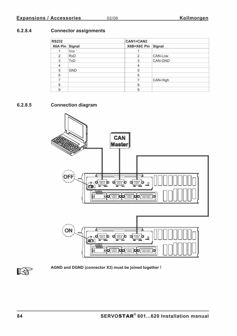
6.2.8.4 Connector assignments . . . . . . . . . . . . . . . . . . . . . . . . . . . . . . . . . . . . . . . . . . . . . . . . . . . . . . . . . . . . . . . . . . . . 84
6.2.8.5 Connection diagram. . . . . . . . . . . . . . . . . . . . . . . . . . . . . . . . . . . . . . . . . . . . . . . . . . . . . . . . . . . . . . . . . . . . . . . 84
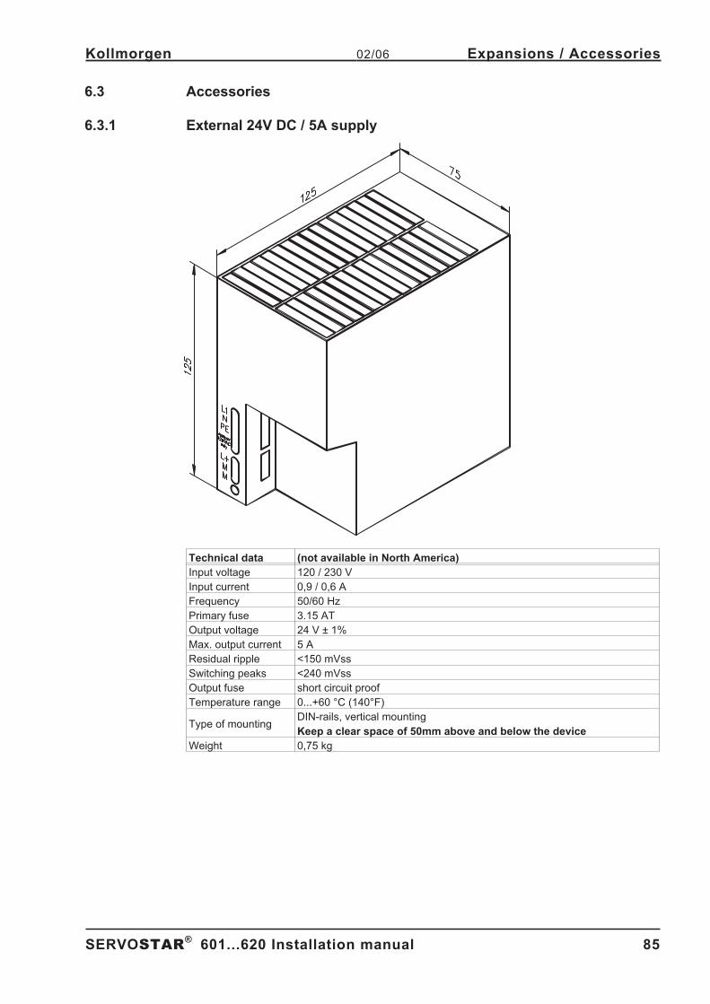
6.3 Accessories . . . . . . . . . . . . . . . . . . . . . . . . . . . . . . . . . . . . . . . . . . . . . . . . . . . . . . . . . . . . . . . . . . . . . . . . . . . . . . . . . . . . . . 85
6.3.1 External 24V DC / 5A supply . . . . . . . . . . . . . . . . . . . . . . . . . . . . . . . . . . . . . . . . . . . . . . . . . . . . . . . . . . . . . . . . . . . . 85
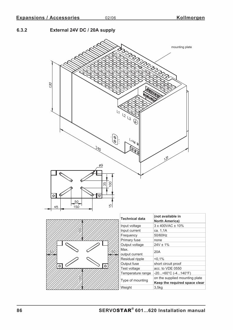
6.3.2 External 24V DC / 20A supply . . . . . . . . . . . . . . . . . . . . . . . . . . . . . . . . . . . . . . . . . . . . . . . . . . . . . . . . . . . . . . . . . . . 86
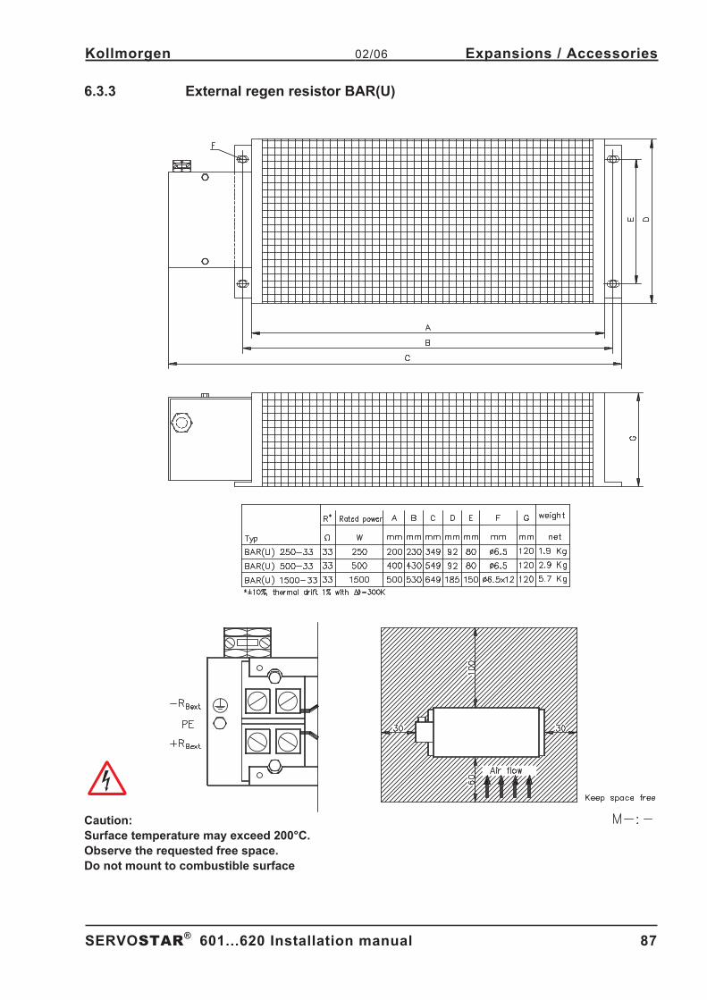
6.3.3 External regen resistor BAR(U) . . . . . . . . . . . . . . . . . . . . . . . . . . . . . . . . . . . . . . . . . . . . . . . . . . . . . . . . . . . . . . . . . . 87
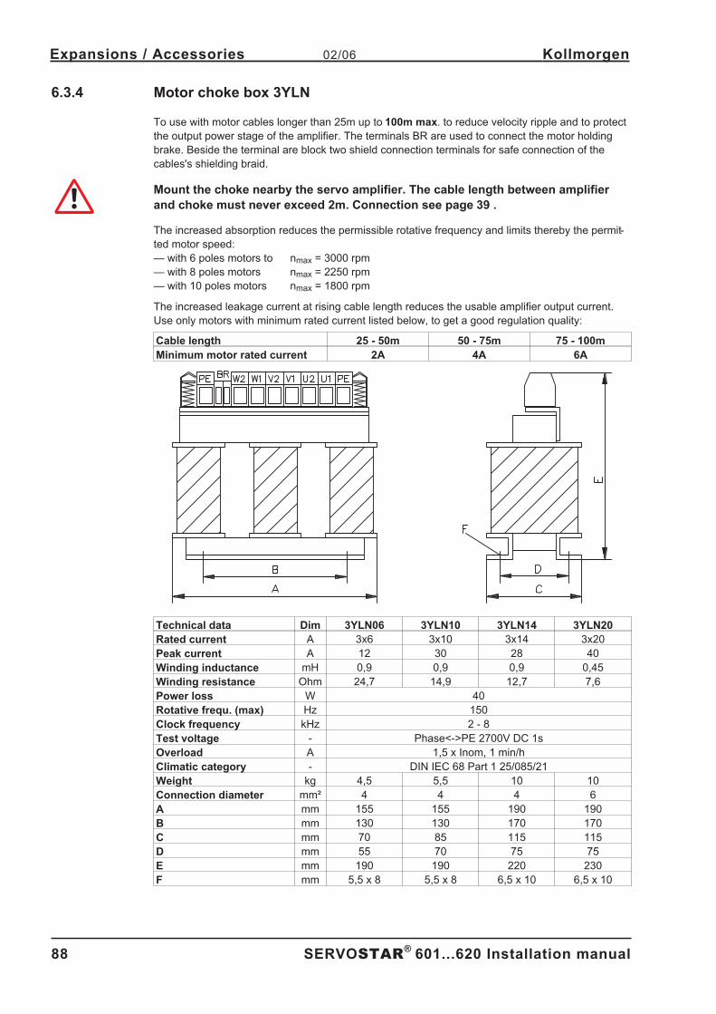
6.3.4 Motor choke box 3YLN . . . . . . . . . . . . . . . . . . . . . . . . . . . . . . . . . . . . . . . . . . . . . . . . . . . . . . . . . . . . . . . . . . . . . . . . 88
6.3.5 Power Supply SINCOS . . . . . . . . . . . . . . . . . . . . . . . . . . . . . . . . . . . . . . . . . . . . . . . . . . . . . . . . . . . . . . . . . . . . . . . . 89
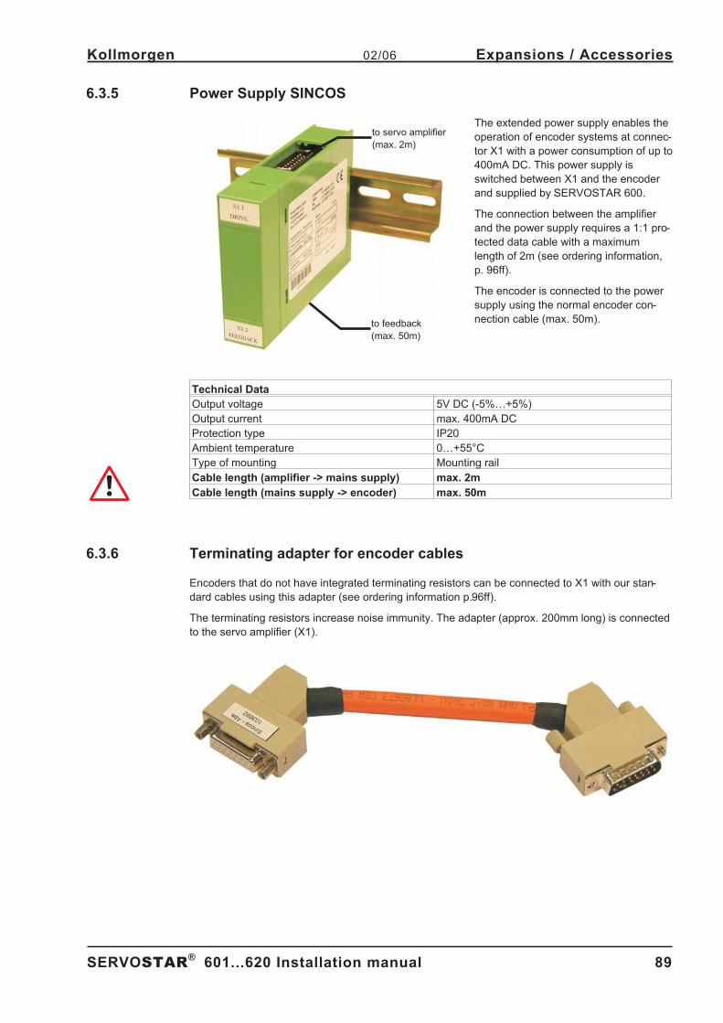
6.3.6 Terminating adapter for encoder cables . . . . . . . . . . . . . . . . . . . . . . . . . . . . . . . . . . . . . . . . . . . . . . . . . . . . . . . . . . . 89
6.3.7 Hall Dongle . . . . . . . . . . . . . . . . . . . . . . . . . . . . . . . . . . . . . . . . . . . . . . . . . . . . . . . . . . . . . . . . . . . . . . . . . . . . . . . . . 90
7 Appendix7.1 Transport, storage, maintenance, disposal. . . . . . . . . . . . . . . . . . . . . . . . . . . . . . . . . . . . . . . . . . . . . . . . . . . . . . . . . . . . . . . 91
7.2 Removing faults/warnings. . . . . . . . . . . . . . . . . . . . . . . . . . . . . . . . . . . . . . . . . . . . . . . . . . . . . . . . . . . . . . . . . . . . . . . . . . . . 92
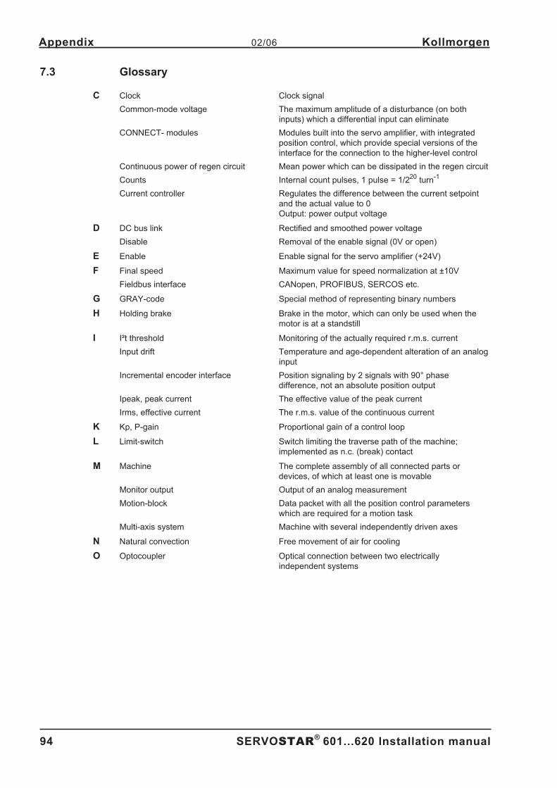
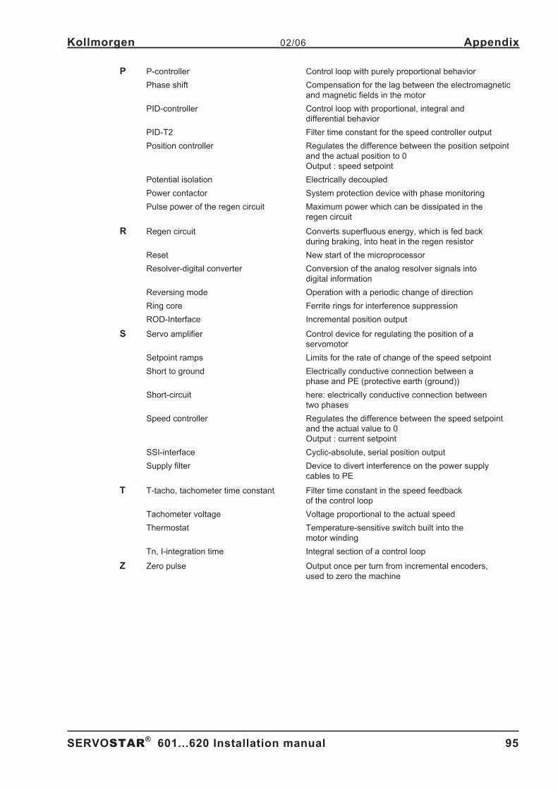
7.3 Glossary . . . . . . . . . . . . . . . . . . . . . . . . . . . . . . . . . . . . . . . . . . . . . . . . . . . . . . . . . . . . . . . . . . . . . . . . . . . . . . . . . . . . . . . . . 94
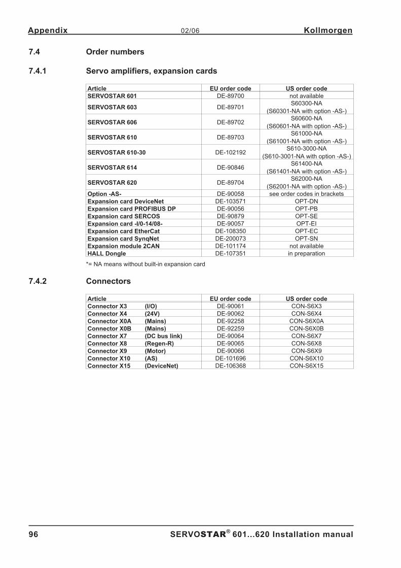
7.4 Order numbers . . . . . . . . . . . . . . . . . . . . . . . . . . . . . . . . . . . . . . . . . . . . . . . . . . . . . . . . . . . . . . . . . . . . . . . . . . . . . . . . . . . . 96
7.4.1 Servo amplifiers, expansion cards . . . . . . . . . . . . . . . . . . . . . . . . . . . . . . . . . . . . . . . . . . . . . . . . . . . . . . . . . . . . . . . 96
7.4.2 Connectors . . . . . . . . . . . . . . . . . . . . . . . . . . . . . . . . . . . . . . . . . . . . . . . . . . . . . . . . . . . . . . . . . . . . . . . . . . . . . . . . . 96
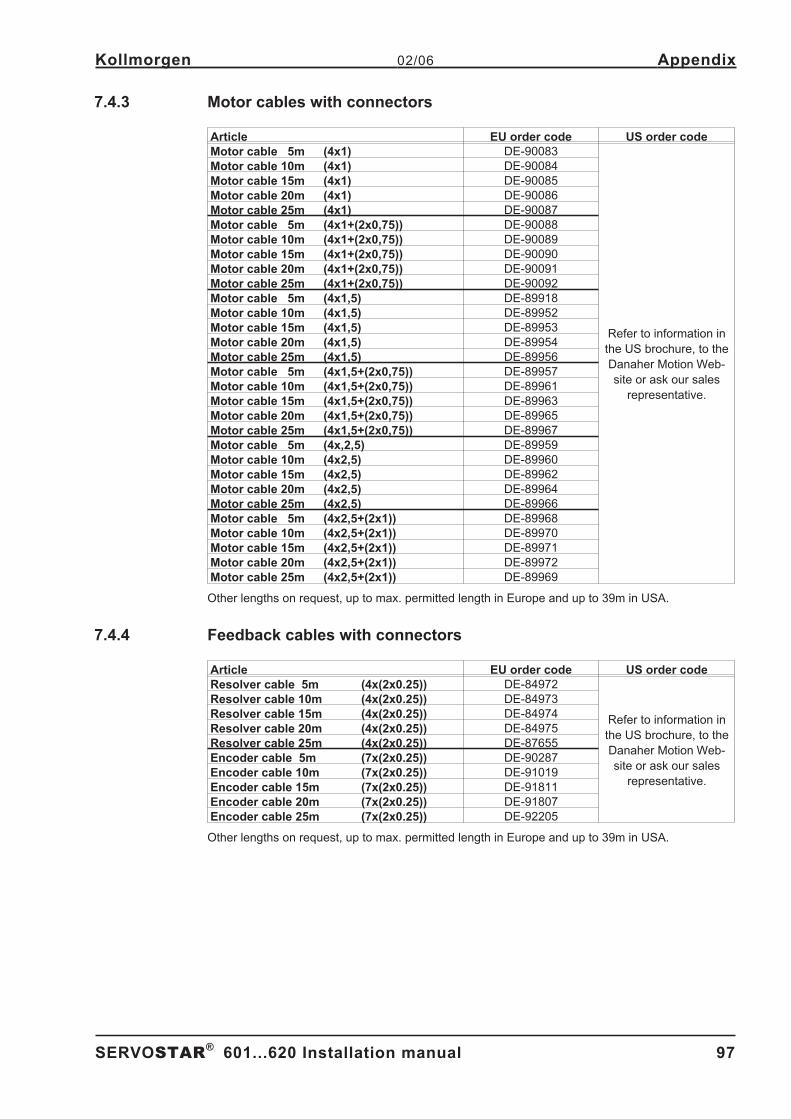
7.4.3 Motor cables with connectors . . . . . . . . . . . . . . . . . . . . . . . . . . . . . . . . . . . . . . . . . . . . . . . . . . . . . . . . . . . . . . . . . . . 97
7.4.4 Feedback cables with connectors . . . . . . . . . . . . . . . . . . . . . . . . . . . . . . . . . . . . . . . . . . . . . . . . . . . . . . . . . . . . . . . . 97
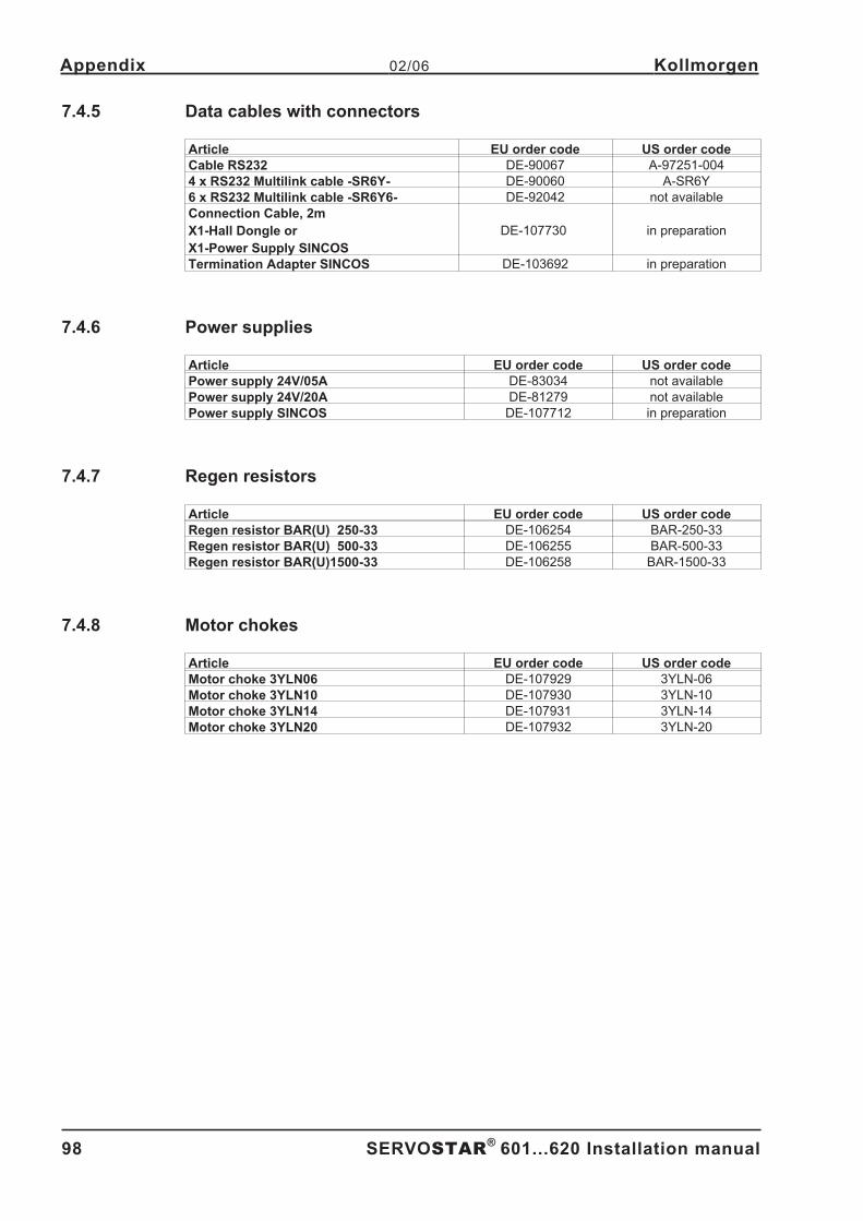
7.4.5 Data cables with connectors . . . . . . . . . . . . . . . . . . . . . . . . . . . . . . . . . . . . . . . . . . . . . . . . . . . . . . . . . . . . . . . . . . . . 98
7.4.6 Power supplies . . . . . . . . . . . . . . . . . . . . . . . . . . . . . . . . . . . . . . . . . . . . . . . . . . . . . . . . . . . . . . . . . . . . . . . . . . . . . . 98
7.4.7 Regen resistors . . . . . . . . . . . . . . . . . . . . . . . . . . . . . . . . . . . . . . . . . . . . . . . . . . . . . . . . . . . . . . . . . . . . . . . . . . . . . . 98
7.4.8 Motor chokes. . . . . . . . . . . . . . . . . . . . . . . . . . . . . . . . . . . . . . . . . . . . . . . . . . . . . . . . . . . . . . . . . . . . . . . . . . . . . . . . 98
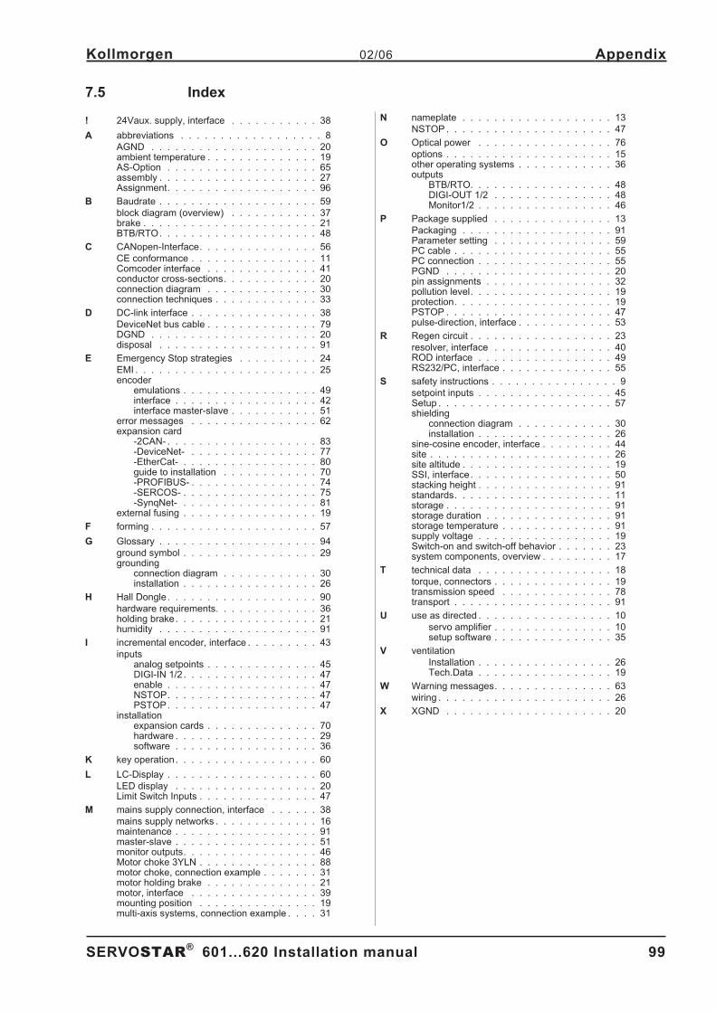
7.5 Index . . . . . . . . . . . . . . . . . . . . . . . . . . . . . . . . . . . . . . . . . . . . . . . . . . . . . . . . . . . . . . . . . . . . . . . . . . . . . . . . . . . . . . . . . . . . 99
SERVOSTAR®
601...620 Installation manual 5
Kollmorgen 02/06 Contents
Page
Page 6
This page has been deliberately left blank.
6 SERVOSTAR®
601...620 Installation manual
02/06 Kollmorgen
Page 7
1 General
1.1 About this manual
This manual describes the digital servo amplifiers of the SERVOSTAR®
600 series
(standard version, 1.5 to 20 Amps nominal current). Servoamplifiers of the SERVOSTAR 640/670
series are described in additional manuals.
SERVOSTAR 601 is sold in Europe only
In this manual you can find information about:
� General Chapter 1
� Technical description Chapter 2
� Assembly / installation Chapter 3
� Interfaces Chapter 4
� Setup Chapter 5
� Expansions / Accessories Chapter 6
� Transport, storage, maintenance, disposal Chapter 7
A more detailed description of the expansion cards which are currently available and the digital
connection to automation systems can be found on the accompanying CD-ROM in Acrobat-Reader
format (system requirements: WINDOWS with Internet browser, Acrobat Reader) in English,
German, Italian and French versions.
You can print this documentation on any standard printer. A printed copy of the documentation is
available from us at extra cost.
This manual makes the following demands on qualified personnel :
Transport : only by personnel with knowledge in handling electrostatically
sensitive components.
Installation : only by electrically qualified personnel
Setup : only by personnel with extensive knowledge of electrical
engineering / drive technology
1.2 Symbols used in this manual
Danger to personnel
from electricity and its
effects
Danger to maschinery,
general warning
Important
notes
� p. see page � special emphasis
SERVOSTAR®
601...620 Installation manual 7
Kollmorgen 02/06 General
Page 8
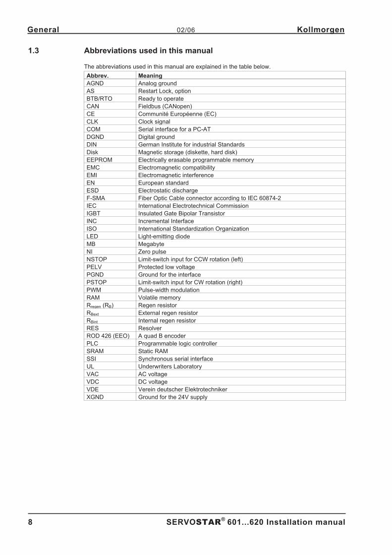
1.3 Abbreviations used in this manual
The abbreviations used in this manual are explained in the table below.
Abbrev. Meaning
AGND Analog ground
AS Restart Lock, option
BTB/RTO Ready to operate
CAN Fieldbus (CANopen)
CE Communité Européenne (EC)
CLK Clock signal
COM Serial interface for a PC-AT
DGND Digital ground
DIN German Institute for industrial Standards
Disk Magnetic storage (diskette, hard disk)
EEPROM Electrically erasable programmable memory
EMC Electromagnetic compatibility
EMI Electromagnetic interference
EN European standard
ESD Electrostatic discharge
F-SMA Fiber Optic Cable connector according to IEC 60874-2
IEC International Electrotechnical Commission
IGBT Insulated Gate Bipolar Transistor
INC Incremental Interface
ISO International Standardization Organization
LED Light-emitting diode
MB Megabyte
NI Zero pulse
NSTOP Limit-switch input for CCW rotation (left)
PELV Protected low voltage
PGND Ground for the interface
PSTOP Limit-switch input for CW rotation (right)
PWM Pulse-width modulation
RAM Volatile memory
Rregen (RB) Regen resistor
RBext External regen resistor
RBint Internal regen resistor
RES Resolver
ROD 426 (EEO) A quad B encoder
PLC Programmable logic controller
SRAM Static RAM
SSI Synchronous serial interface
UL Underwriters Laboratory
VAC AC voltage
VDC DC voltage
VDE Verein deutscher Elektrotechniker
XGND Ground for the 24V supply
8 SERVOSTAR®
601...620 Installation manual
General 02/06 Kollmorgen
Page 9
2 Technical Description
2.1 Safety Instructions
� Only properly qualified personnel are permitted to perform activities such as trans-
port, installation, setup and maintenance. Properly qualified persons are those who
are familiar with the transport, assembly, installation, setup and operation of the pro-
duct, and who have the appropriate qualifications for their job. The qualified person-
nel must know and observe:
IEC 364 and CENELEC HD 384 or DIN VDE 0100
IEC-Report 664 or DIN VDE 0110
National Accident Prevention Regulations or BGV A3
� Read this documentation before carrying out installation and setup. Incorrect hand-
ling of the servo amplifier can lead to personal injury or material damage. It is vital
that you keep to the technical data and information on connection requirements (on
the nameplate and in the documentation).
� The servo amplifiers contain electrostatically sensitive components which may be
damaged by incorrect handling. Ground yourself before touching the servo amplifier
by touching any unpainted metal surface. Avoid contact with highly insulating mater-
ials (artificial fabrics, plastic film etc.). Place the servo amplifier on a conductive sur-
face.
� The manufacturer of the machine must generate a hazard analysis for the machine,
and take appropriate measures to ensure that unforeseen movements cannot cause
injury or damage to any person or property.
� Do not open the units. Keep all covers and switchgear cabinet doors closed during
operation. Otherwise there are deadly hazards, with the possibility of severe danger
to health or material damage.
� During operation, servo amplifiers, according to their degree of enclosure protection,
may have uncovered live components. Control and power connections may be live,
even if the motor is not rotating.
� Servo amplifiers may have hot surfaces during operation. Since the front panel is
used for cooling, it can reach temperatures above 80°C (176°F).
� Never undo the electrical connections to the servo amplifier while it is live. There is a
danger of electric arcing with damage to contacts and danger to persons.
� Wait at least five minutes after disconnecting the servo amplifier from the mains
supply voltage before touching live sections of the equipment (e.g. contacts) or
undoing connections. Capacitors can still have dangerous voltages present up to five
minutes after switching off the supply voltages. To be sure, measure the voltage in
the DC bus link circuit and wait until it has fallen below 40V.
SERVOSTAR®
601...620 Installation manual 9
Kollmorgen 02/06 Technical Description
Page 10
2.2 Use as directed
The servo amplifiers are components which are built into electrical equipment or machines, and can
only be used as integral components of such equipment.
The manufacturer of the machine must generate a hazard analysis for the machine, and take
appropriate measures to ensure that unforeseen movements cannot cause injury or damage to any
person or property.
The SERVOSTAR 600 family of servo amplifiers can be connected directly to symmetrically earthed
(grounded) three-phase industrial mains supply networks [TN-system, TT-system with earthed
(grounded) neutral point, not more than 5000 rms symmetrical amperes, 480VAC maximum].
The servo amplifiers must not be operated directly on power supply networks >230V without an
earth (ground) or with an asymmetrical earth (ground).
Connection to different mains supply networks (with additional isolating transformer)� p.16.
Periodic overvoltages between outer conductor (L1, L2, L3) and housing of the servo amplifier may
not exceed 1000V (peak value).
Transient overvoltages (< 50µs) between the outer conductors may not exceed 1000V.
Transient overvoltages (< 50µs) between outer conductors and housing may not exceed 2000V.
If the servo amplifiers are used in residential areas, or in business or commercial premises, then
additional filter measures must be implemented by the user.
The SERVOSTAR 600 family of servo amplifiers is only intended to drive specific brushless
synchronous servomotors, with closed-loop control of torque, speed and/or position. The rated volt-
age of the motors must be at least as high as the DC bus link voltage of the servo amplifier.
The servo amplifiers may only be operated in a closed switchgear cabinet, taking into account the
ambient conditions defined on page 19 and the dimensions shown on page 27. Ventilation or cool-
ing may be necessary to prevent enclosure ambient from exceeding 45°C (113°F).
Use only copper wire. Wire size may be determined from EN 60204 (or table 310-16 of the NEC
60°C or 75°C column for AWG size).
We only guarantee the conformance of the servo amplifiers with the standards for industrial areas
(page 11), if the components (motors, cables, amplifiers etc) are delivered by Danaher Motion.
Option -AS-, restart lock for personnel safety
The -AS- restart lock is exclusively intended to provide safety for personnel, by preventing the
restart of a system. To achieve this personnel safety, the wiring of the safety circuits must meet the
safety requirements of EN60204, EN292 and EN 954-1.
The -AS- restart lock must only be activated,
— when the motor is no longer rotating (setpoint = 0V, speed = 0rpm, enable = 0V).
Drives with a suspended load must have an additional safe mechanical blocking
(e.g. by a motor-holding brake).
— when the monitoring contacts (KSO1/2 and BTB/RTO) for all servo amplifiers are
wired into the control signal loop (to recognize a cable break).
The -AS- restart lock may only be controlled by a CNC if the control of the internal safety relay is
arranged for redundant monitoring.
The -AS- restart lock must not be used if the drive is to be made inactive for the following reasons :
1. - cleaning, maintenance and repair operations
- long inoperative periods
In such cases, the entire system should be disconnected from the supply by the personnel,
and secured (main switch).
2. - emergency-stop situations
In an emergency-stop situation, the main contactor is switched off
(by the emergency-stop button or the BTB-contact in the safety circuit).Safety instructions
10 SERVOSTAR®
601...620 Installation manual
Technical Description 02/06 Kollmorgen
Page 11
2.3 European Directives and Standards
Servo amplifiers are components that are intended to be incorporated into electrical plant and
machines for industrial use. When the servo amplifiers are built into machines or plant, the amplifier
must not be used until it has been established that the machine or equipment fulfills the require-
ments of the EC Machinery Directive (98/37/EC), the EC EMC Directive (89/336/EEC) and the EC
Low Voltage Directive 73/23/EEC.
Standards to be applied for conformance with the EC Machinery Directive (98/37/EC):
EN 60204-1 (Safety and Electrical Equipment in Machines)
EN 292 (Safety of Machines)
The manufacturer of the machine must generate a hazard analysis for the machine,
and must implement appropriate measures to ensure that unforeseen movements
cannot cause injury or damage to any person or property.
Standards to be applied for conformance with the EC Low Voltage Directive (73/23/EEC):
EN 60204-1 (Safety and Electrical Equipment in Machines)
EN 50178 (Electronic Equipment in Power Installations)
EN 60439-1 (Low Voltage Switchgear Combinations)
Standards to be applied for conformance with the EC EMC Directive (89/336/EEC):
EN 61000-6-1 / EN 61000-6-2 (Interference Immunity in Residential & Industrial Areas)
EN 61000-6-3 / EN 61000-6-4 (Interference Generation in Residential & Industrial Areas)
The manufacturer of the machine/plant is responsible for ensuring that it meets the limits required
by the EMC regulations. Advice on the correct installation for EMC (such as shielding, grounding,
treatment of connectors and cable layout) can be found in this documentation.
The machine/plant manufacturer must check whether other standards or EC
Directives must be applied to the machine/plant.
2.4 CE conformance
Conformance with the EC EMC Directive 89/336/EEC and the Low Voltage Directive 73/23/EEC is
mandatory for the supply of servo amplifiers within the European Community. Product standard EN
61800-3 is applied to ensure conformance with the EMC Directive. The Declaration of Conformity
form can be found on our website (download area).
Concerning noise immunity the servo amplifier meets the requirements to the 2nd environmental
category (industrial environment). For noise emission the amplifier meets the requirement to a prod-
uct of the category C3.
Warning! This product can cause high-frequency interferences in non industrial
environments which can require measures for interference suppression.
The servo amplifiers have been tested in a defined configuration, using the system components that
are described in this documentation. Any divergence from the configuration and installation
described in this documentation means that you will be responsible for carrying out new measure-
ments to ensure conformance with regulatory requirements. The standard EN 50178 is applied to
ensure conformance with the Low Voltage Directive.
SERVOSTAR®
601...620 Installation manual 11
Kollmorgen 02/06 Technical Description
Page 12
2.5 UL and cUL- Conformance
This servo amplifier is listed under UL file number E217428.
UL (cUL)-certified servo amplifiers (Underwriters Laboratories Inc.) fulfil the relevant U.S. and Cana-
dian standard (in this case UL 840 and UL 508C).
This standard describes the fulfilment by design of minimum requirements for electrically operated
power conversion equipment, such as frequency converters and servo amplifiers, which is intended
to eliminate the risk of fire, electric shock, or injury to persons, being caused by such equipment.
The technical conformance with the U.S. and Canadian standard is determined by an independent
UL (cUL) inspector through the type testing and regular check-ups.
Apart from the notes on installation and safety in the documentation, the customer does not have to
observe any other points in direct connection with the UL (cUL)-certification of the equipment.
UL 508C
UL 508C describes the fulfilment by design of minimum requirements for electrically operated power
conversion equipment, such as frequency converters and servo amplifiers, which is intended to
eliminate the risk of fire being caused by such equipment.
UL 840
UL 840 describes the fulfilment by design of air and insulation creepage spacings for electrical
equipment and printed circuit boards.
12 SERVOSTAR®
601...620 Installation manual
Technical Description 02/06 Kollmorgen
Page 13
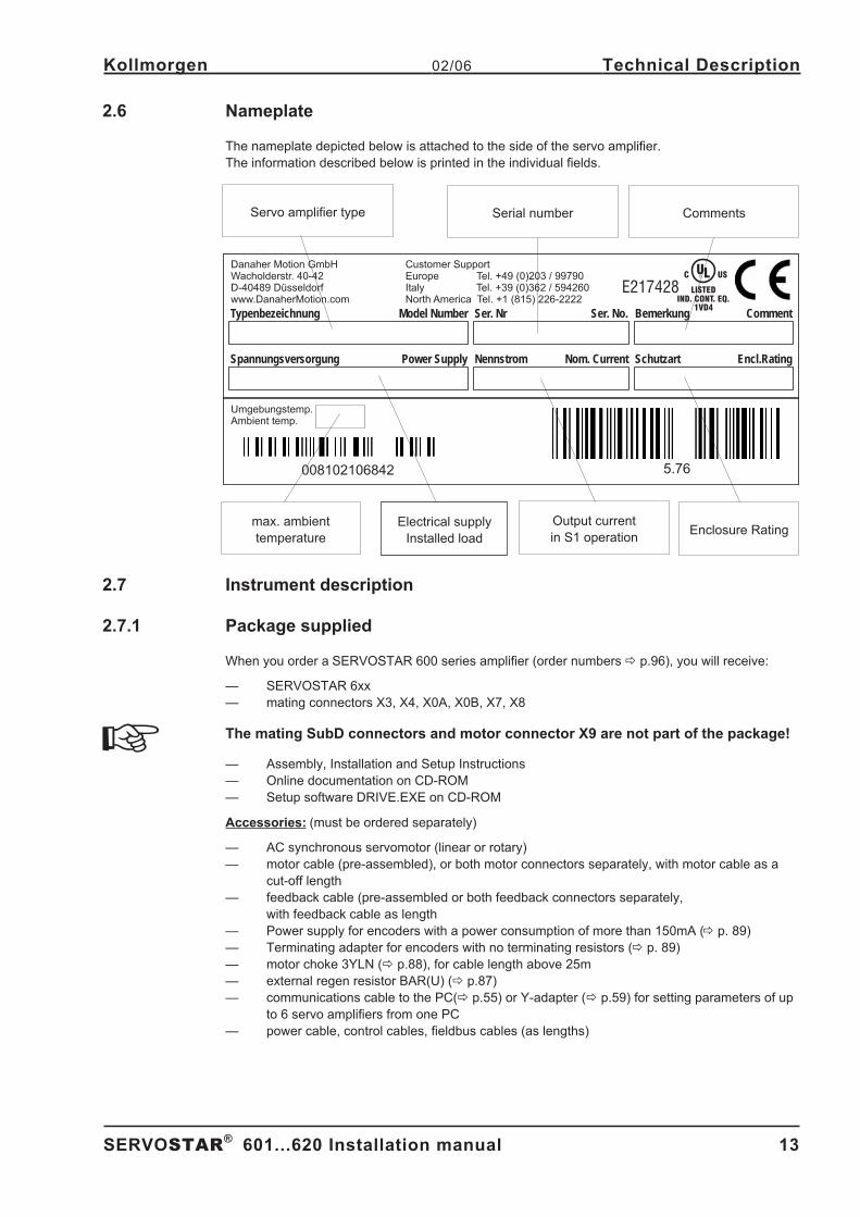
2.6 Nameplate
The nameplate depicted below is attached to the side of the servo amplifier.
The information described below is printed in the individual fields.
2.7 Instrument description
2.7.1 Package supplied
When you order a SERVOSTAR 600 series amplifier (order numbers� p.96), you will receive:
— SERVOSTAR 6xx
— mating connectors X3, X4, X0A, X0B, X7, X8
The mating SubD connectors and motor connector X9 are not part of the package!
— Assembly, Installation and Setup Instructions
— Online documentation on CD-ROM
— Setup software DRIVE.EXE on CD-ROM
Accessories: (must be ordered separately)
— AC synchronous servomotor (linear or rotary)
— motor cable (pre-assembled), or both motor connectors separately, with motor cable as a
cut-off length
— feedback cable (pre-assembled or both feedback connectors separately,
with feedback cable as length
— Power supply for encoders with a power consumption of more than 150mA (� p. 89)
— Terminating adapter for encoders with no terminating resistors (� p. 89)
— motor choke 3YLN (� p.88), for cable length above 25m
— external regen resistor BAR(U) (� p.87)
— communications cable to the PC(� p.55) or Y-adapter (� p.59) for setting parameters of up
to 6 servo amplifiers from one PC
— power cable, control cables, fieldbus cables (as lengths) - A.4.028.6/10
SERVOSTAR®
601...620 Installation manual 13
Kollmorgen 02/06 Technical Description
Typenbezeichnung
Spannungsversorgung
Model Number
Power Supply
Ser. Nr
Nennstrom
Ser. No.
Nom. Current
Bemerkung
Schutzart
Comment
Encl.Rating
Danaher Motion GmbHWacholderstr. 40-42D-40489 Düsseldorfwww.DanaherMotion.com
Customer SupportEurope Tel. +49 (0)203 / 99790Italy 3 36 594260North America 1 8 -
Tel. + 9 (0) 2 /Tel. + ( 15) 226 2222
Umgebungstemp.Ambient temp.
E217428
1VD4
LISTEDIND. CONT. EQ.
C USUL®
5.76008102106842
CommentsSerial numberServo amplifier type
max. ambient
temperature
Output current
in S1 operationEnclosure Rating
Electrical supply
Installed load
Page 14
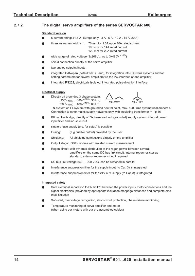
2.7.2 The digital servo amplifiers of the series SERVOSTAR 600
Standard version
� 6 current ratings (1.5 A -Europe only-, 3 A , 6 A , 10 A , 14 A, 20 A)
� three instrument widths : 70 mm for 1.5A up to 10A rated current
100 mm for 14A rated current
120 mm for 20A rated current
� wide range of rated voltage (3x208V –10% to 3x480V+10%
)
� shield connection directly at the servo amplifier
� two analog setpoint inputs
� integrated CANopen (default 500 kBaud), for integration into CAN bus systems and for
setting parameters for several amplifiers via the PC-interface of one amplifier
� integrated RS232, electrically isolated, integrated pulse-direction interface
Electrical supply
� Directly off grounded 3 phase system,
230V-10% ... 480V+10%
, 50 Hz,
208V-10% ... 480V+10%
, 60 Hz
TN-system or TT-system with grounded neutral point, max. 5000 rms symmetrical amperes.
Connection to other mains supply networks only with insulating transformer� p.16
� B6 rectifier bridge, directly off 3-phase earthed (grounded) supply system, integral power
input filter and inrush circuit
� single-phase supply (e.g. for setup) is possible
� Fusing: (e.g. fusible cutout) provided by the user
� Shielding: All shielding connections directly on the amplifier
� Output stage: IGBT- module with isolated current measurement
� Regen circuit: with dynamic distribution of the regen power between several
amplifiers on the same DC bus link circuit. Internal regen resistor as
standard, external regen resistors if required
� DC bus link voltage 260 — 900 VDC, can be switched in parallel
� Interference suppression filter for the supply input (to Cat. 3) is integrated
� Interference suppression filter for the 24V aux. supply (to Cat. 3) is integrated
Integrated safety
� Safe electrical separation to EN 50178 between the power input / motor connections and the
signal electronics, provided by appropriate insulation/creepage distances and complete elec-
trical isolation
� Soft-start, overvoltage recognition, short-circuit protection, phase-failure monitoring
� Temperature monitoring of servo amplifier and motor
(when using our motors with our pre-assembled cables)
14 SERVOSTAR®
601...620 Installation manual
Technical Description 02/06 Kollmorgen
Page 15
Auxiliary supply voltage 24VDC
� Electrically isolated, internal fusing (3.15 AT), from an external 24VDC psu, e.g. with insula-
ting transformer
Operation and parameter setting
� With our user-friendly software for setup through the serial interface of a PC
� Direct operation by means of two keys on the servo amplifier and a 3-character LED display
for status display in case there is no PC available
� Fully programmable via RS232 interface
Completely digital control
� Digital current controller (space vector pulse-width modulation, 62.5 µs)
� digital speed controller adaptable to most different load conditions (65µs or 250 µs)
� Integral position controller with adaptation possibilities for customer needs (250 µs)
� Pulse direction interface integrated for connection of a servomotor to a stepping motor
control
� Evaluation of the resolver signals and sine-cosine signals of a high-resolution encoder
� Encoder simulation (incremental or SSI)
Auxiliary functions
� 2 analog monitor outputs
� 4 programmable digital inputs (normally, two are defined as limit-switch inputs)
� 2 programmable digital outputs
� Freely programmable combinations of all digital signals
Options/Expansions
� -AS- built-in safety relay (personnel-safety starting lock-out)� p. 65
� I/O expansion card� p. 71
� PROFIBUS DP expansion card� p. 74
� SERCOS expansion card� p. 75
� DeviceNet expansion card� p. 77
� EtherCat expansion card� p. 80
� SynqNet expansion card� p. 81
� -2CAN- expansion module, separated connectors for CAN bus and RS232� p. 83
� Third party expansion cards (ModBus, FireWire, LightBus etc. - contact distributors for furt-
her information)
SERVOSTAR®
601...620 Installation manual 15
Kollmorgen 02/06 Technical Description
Page 16
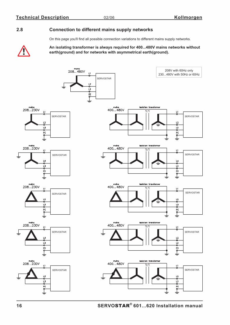
2.8 Connection to different mains supply networks
On this page you'll find all possible connection variations to different mains supply networks.
An isolating transformer is always required for 400...480V mains networks without
earth(ground) and for networks with asymmetrical earth(ground).
- A.4.031.1/52
16 SERVOSTAR®
601...620 Installation manual
Technical Description 02/06 Kollmorgen
SERVOSTAR
SERVOSTAR
SERVOSTAR
SERVOSTAR
SERVOSTAR
SERVOSTAR
SERVOSTAR
SERVOSTAR
SERVOSTAR
SERVOSTAR
SERVOSTAR
208V with 60Hz only
230...480V with 50Hz or 60Hz
Page 17
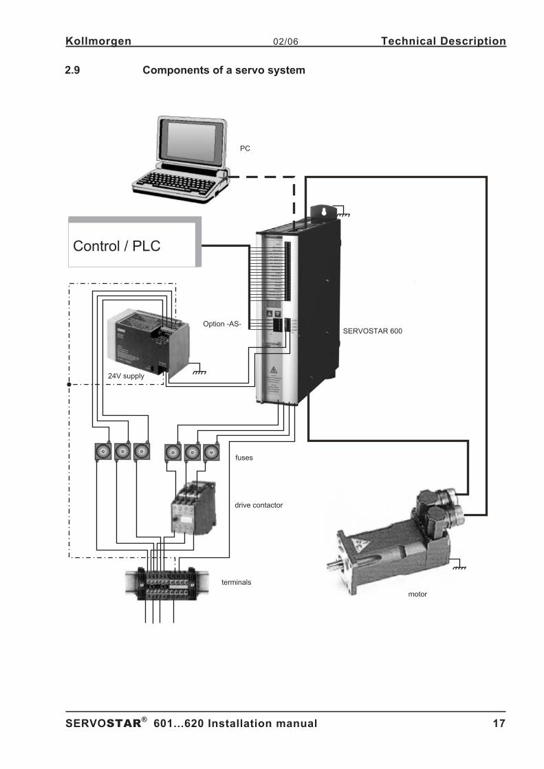
2.9 Components of a servo system
SERVOSTAR®
601...620 Installation manual 17
Kollmorgen 02/06 Technical Description
24V supply
fuses
drive contactor
terminals
motor
SERVOSTAR 600
PC
Control / PLC
Option -AS-
Page 18
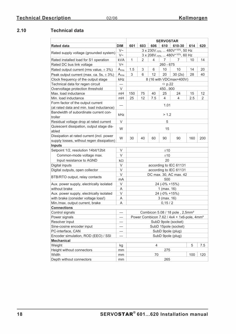
2.10 Technical data
SERVOSTAR
Rated data DIM 601 603 606 610 610-30 614 620
Rated supply voltage (grounded system)V~ 3 x 230V-10% ... 480V+10%, 50 Hz
V~ 3 x 208V-10% ... 480V+10%, 60 Hz
Rated installed load for S1 operation kVA 1 2 4 7 7 10 14
Rated DC bus link voltage V= 260 - 675
Rated output current (rms value, � 3%) Arms 1.5 3 6 10 10 14 20
Peak output current (max. ca. 5s, � 3%) Arms 3 6 12 20 30 (2s) 28 40
Clock frequency of the output stage kHz 8 (16 with VDCmax=400V)
Technical data for regen circuit — � p.22
Overvoltage protection threshold V 450...900
Max. load inductance mH 150 75 40 25 24 15 12
Min. load inductance mH 25 12 7.5 4 4 2.5 2
Form factor of the output current
(at rated data and min. load inductance)— 1.01
Bandwidth of subordinate current con-
trollerkHz > 1.2
Residual voltage drop at rated current V 5
Quiescent dissipation, output stage dis-
abledW 15
Dissipation at rated current (incl. power
supply losses, without regen dissipation)W 30 40 60 90 90 160 200
Inputs
Setpoint 1/2, resolution 14bit/12bit V �10
Common-mode voltage max. V �10
Input resistance to AGND k� 20
Digital inputs V according to IEC 61131
Digital outputs, open collector V according to IEC 61131
BTB/RTO output, relay contactsV DC max. 30, AC max. 42
mA 500
Aux. power supply, electrically isolated
without brake
V 24 (-0% +15%)
A 1 (max. 16)
Aux. power supply, electrically isolated
with brake (consider voltage loss!)
V 24 (-0% +15%)
A 3 (max. 16)
Min./max. output current, brake A 0,15 / 2
Connections
Control signals — Combicon 5.08 / 18 pole , 2,5mm²
Power signals — Power Combicon 7.62 / 4x4 + 1x6-pole, 4mm²
Resolver input — SubD 9pole (socket)
Sine-cosine encoder input — SubD 15pole (socket)
PC-interface, CAN — SubD 9pole (plug)
Encoder simulation, ROD (EEO) / SSI — SubD 9pole (plug)
Mechanical
Weight kg 4 5 7.5
Height without connectors mm 275
Width mm 70 100 120
Depth without connectors mm 265
18 SERVOSTAR®
601...620 Installation manual
Technical Description 02/06 Kollmorgen
Page 19
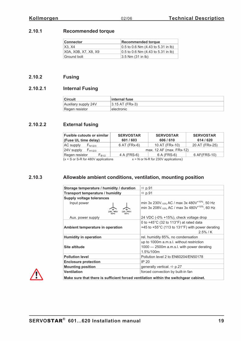
2.10.1 Recommended torque
Connector Recommended torque
X3, X4 0.5 to 0.6 Nm (4.43 to 5.31 in lb)
X0A, X0B, X7, X8, X9 0.5 to 0.6 Nm (4.43 to 5.31 in lb)
Ground bolt 3.5 Nm (31 in lb)
2.10.2 Fusing
2.10.2.1 Internal Fusing
Circuit internal fuse
Auxiliary supply 24V 3.15 AT (FRx-3)
Regen resistor electronic
2.10.2.2 External fusing
Fusible cutouts or similar
(Fuse UL time delay)
SERVOSTAR
601 / 603
SERVOSTAR
606 / 610
SERVOSTAR
614 / 620
AC supply FN1/2/3 6 AT (FRx-6) 10 AT (FRx-10) 20 AT (FRx-25)
24V supply FH1/2/3 max. 12 AF (max. FRx-12)
Regen resistor FB1/2 4 A (FRS-6) 6 A (FRS-6) 6 AF(FRS-10)(x = S or S-R for 480V applications x = N or N-R for 230V applications)
2.10.3 Allowable ambient conditions, ventilation, mounting position
Storage temperature / humidity / duration � p.91
Transport temperature / humidity � p.91
Supply voltage tolerances
Input power
Aux. power supply
min 3x 230V-10% AC / max 3x 480V+10%, 50 Hz
min 3x 208V-10% AC / max 3x 480V+10%, 60 Hz
24 VDC (-0% +15%), check voltage drop
Ambient temperature in operation
0 to +45°C (32 to 113°F) at rated data
+45 to +55°C (113 to 131°F) with power derating
2.5% / K
Humidity in operation rel. humidity 85%, no condensation
Site altitude
up to 1000m a.m.s.l. without restriction
1000 — 2500m a.m.s.l. with power derating
1.5%/100m
Pollution level Pollution level 2 to EN60204/EN50178
Enclosure protection IP 20
Mounting position generally vertical.� p.27
Ventilation forced convection by built-in fan
Make sure that there is sufficient forced ventilation within the switchgear cabinet.
SERVOSTAR®
601...620 Installation manual 19
Kollmorgen 02/06 Technical Description
Page 20
2.10.4 Conductor cross-sections
Technical data for connection cables� p.34.Following EN 60204 (for AWG: table 310-16 of the NEC 60°C or 75°C column), we recommend for
single-axis systems:
AC connectionSERVOSTAR 601-610: 1.5 mm² (14awg)
SERVOSTAR 614/620 : 4 mm² (12awg)
600V,105°C (221°F),
twisted
DC bus linkSERVOSTAR 601-610: 1.5 mm² (14awg)
SERVOSTAR 614/620: 4 mm² (12awg)
600V,105°C (221°F),
shielded for
lengths>20cm
Motor cables
up to 25 m length*
SERVOSTAR 601-610: 1-1.5 mm² (14awg)
SERVOSTAR 614/620: 2.5 mm² (12awg)
600V,105°C (221°F),
shielded,
capacitance <150pF/m
Motor cables
25 to 100 m length*,
with motor choke 3YLN
(consult our customer
service)
SERVOSTAR 601-606: 1 mm² (14awg)
SERVOSTAR 610-620: 2.5 mm² (12awg)
600V,105°C (221°F),
shielded,
capacitance <150pF/m
Resolver, thermostat-mo-
tor, max.100m length*
4x2x0.25 mm² (22awg) twisted pairs, shielded,
capacitance <120pF/m
Encoder, thermostat-motor,
max.50m length*
7x2x0,25 mm² (22 awg) twisted pairs, shielded,
capacitance <120pF/m
Setpoints, monitors, AGND 0.25 mm² (22awg) twisted pairs, shielded
Control signals, BTB,
DGND0.5 mm² (20awg)
Holding brake (motor)min. 0.75 mm² (18awg), 600V,105°C (221°F), shielded,
check voltage drop
+24 V / XGND max. 2.5 mm² (12awg), check voltage drop
For multi-axis systems, please note the special operating conditions in your installation
* Danaher Motion North America delivers cables up to 39m length.
* Danaher Motion Europe delivers cables up to the maximum length.
2.10.5 LED display
A 3-character LED display shows the amplifier status after switching on the 24V supply
(� p.60). During operation of the amplifier via the keys on the front panel, the parameter and func-
tion numbers (� p.61) are displayed, as well as the numbers of any errors which occur
(� p.62).
2.11 Grounding system
AGND — ground for analog inputs/outputs, internal analog/µC ground
DGND — ground for digital inputs/outputs, optically isolated
XGND — ground for external 24V aux. voltage, optically and inductively isolated
PGND — ground for encoder simulation, RS232, CAN, optically isolated
The potential isolation is shown in the block diagram (� p. 37).
20 SERVOSTAR®
601...620 Installation manual
Technical Description 02/06 Kollmorgen
Page 21
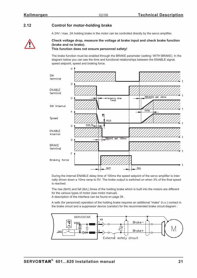
2.12 Control for motor-holding brake
A 24V / max. 2A holding brake in the motor can be controlled directly by the servo amplifier.
Check voltage drop, measure the voltage at brake input and check brake function
(brake and no brake).
This function does not ensure personnel safety!
The brake function must be enabled through the BRAKE parameter (setting: WITH BRAKE). In the
diagram below you can see the time and functional relationships between the ENABLE signal,
speed setpoint, speed and braking force.
During the internal ENABLE delay time of 100ms the speed setpoint of the servo amplifier is inter-
nally driven down a 10ms ramp to 0V. The brake output is switched on when 3% of the final speed
is reached.
The rise (tbrH) and fall (tbrL) times of the holding brake which is built into the motors are different
for the various types of motor (see motor manual).
A description of the interface can be found on page 39 .
A safe (for personnel) operation of the holding brake requires an additional “make” (n.o.) contact in
the brake circuit and a suppressor device (varistor) for the recommended brake circuit diagram : -A.4.031.3/01, 1/35
SERVOSTAR®
601...620 Installation manual 21
Kollmorgen 02/06 Technical Description
SERVOSTAR
Page 22
2.13 Regen circuit
During braking with the aid of the motor, energy is fed back to the servo amplifier. This energy is
converted into heat in the regen resistor. The regen circuit (thresholds) are adjusted to the supply
voltage with the help of the setup software.
Our customer service can help you with the calculation of the regen power which is required. A
description of the interface can be found on page 39.
Internal regen resistor
SERVOSTAR 601/603 66 �
SERVOSTAR 606-620 33 �
External regen resistor (see p. 87)
SERVOSTAR 601-620 33 �
Functional description
1.- Individual amplifiers, not coupled through the DC bus link (DC+, DC-)
The circuit starts to respond at a DC bus link voltage of 400V, 720V or 840V (depending on
the supply voltage).
If the energy which is fed back from the motor, as an average over time or as a peak value,
is higher than the preset regen power, then the servo amplifier will output the status “regen
power exceeded” and the regen circuit will be switched off.
At the next internal check of the DC bus link voltage (after a few ms) an overvoltage will be
detected and the servo amplifier will be switched off with the error message “Overvoltage
F02" (� p.62).
The BTB/RTO contact (terminal X3/2,3) will be opened at the same time (� p.48)
2.- Several servo amplifiers coupled through the DC bus link circuit (DC+, DC-)
Thanks to the built-in regen circuit with its patented power distribution, several amplifiers
(even with different current ratings) can be operated off a common DC bus link. This is
achieved by an automatic adjustment of the regen thresholds (which vary, because of toler-
ances). The regen energy is distributed equally among all the amplifiers.
The combined power of all the amplifiers is always available, as continuous or peak power.
The switch-off takes place as described under 1. (above) for the servo amplifier with the
lowest switch-off threshold (resulting from tolerances). The RTO (BTB) contact of this ampli-
fier (terminals X3/2,3) will be opened at the same time (� p.48).
Technical Data
The technical data depend on the used servo amplifier type and on the mains voltage. See table on
the next page.
22 SERVOSTAR®
601...620 Installation manual
Technical Description 02/06 Kollmorgen
Page 23
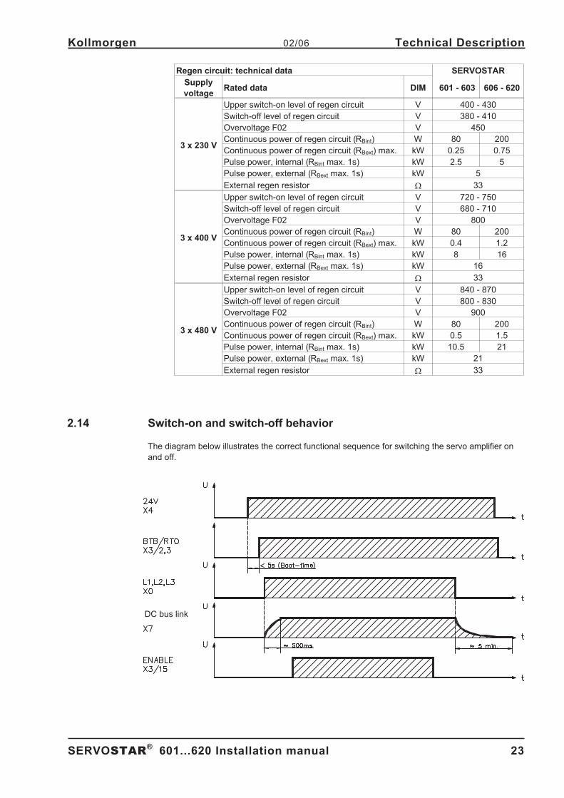
Regen circuit: technical data SERVOSTAR
Supply
voltageRated data DIM 601 - 603 606 - 620
3 x 230 V
Upper switch-on level of regen circuit V 400 - 430
Switch-off level of regen circuit V 380 - 410
Overvoltage F02 V 450
Continuous power of regen circuit (RBint) W 80 200
Continuous power of regen circuit (RBext) max. kW 0.25 0.75
Pulse power, internal (RBint max. 1s) kW 2.5 5
Pulse power, external (RBext max. 1s) kW 5
External regen resistor � 33
3 x 400 V
Upper switch-on level of regen circuit V 720 - 750
Switch-off level of regen circuit V 680 - 710
Overvoltage F02 V 800
Continuous power of regen circuit (RBint) W 80 200
Continuous power of regen circuit (RBext) max. kW 0.4 1.2
Pulse power, internal (RBint max. 1s) kW 8 16
Pulse power, external (RBext max. 1s) kW 16
External regen resistor � 33
3 x 480 V
Upper switch-on level of regen circuit V 840 - 870
Switch-off level of regen circuit V 800 - 830
Overvoltage F02 V 900
Continuous power of regen circuit (RBint) W 80 200
Continuous power of regen circuit (RBext) max. kW 0.5 1.5
Pulse power, internal (RBint max. 1s) kW 10.5 21
Pulse power, external (RBext max. 1s) kW 21
External regen resistor � 33
2.14 Switch-on and switch-off behavior
The diagram below illustrates the correct functional sequence for switching the servo amplifier on
and off.
SERVOSTAR®
601...620 Installation manual 23
Kollmorgen 02/06 Technical Description
DC bus link
Page 24
2.14.1 Stop function to EN 60204 (VDE 0113)
If a fault occurs (� p.62) the output stage of the servo amplifier is switched off and the BTB/RTO
contact is opened. In addition, a global error signal can be given out at one of the digital outputs
(terminals X3/16 and X3/17) (see online help for the setup software). These signals can be used by
the higher-level control to finish the current PLC cycle or to shut down the drive (with additional
brake or similar.).
Instruments which are equipped with a selected “Brake” function use a special sequence for
switching off the output stage (� p.21).
The -AS- option can be used to switch off the drive via a positive-action (approved by the Trade
Liability Association) safety relay, so that personnel safety is ensured at the drive shaft (� p.65).
The Stop functions are defined in EN 60204 (VDE 0113), Para. 9.2.2, 9.2.5.3.
There are three categories of Stop functions:
Category 0: Shut down by immediately switching off the supply of energy to the
drive machinery (i.e an uncontrolled shut-down);
Category 1: A controlled shut-down, during which the supply of energy to the drive
machinery is maintained to perform the shut-down, and where the energy
supply is only interrupted when the shut-down has been completed;
Category 2: A controlled shut-down, where the supply of energy to the drive machinery
is maintained.
Every machine must be equipped with a Stop function to Category 0. Stop functions to Categories 1
and/or 2 must be provided if the safety or functional requirements of the machine make this
necessary.
You can find additional information and implementation examples in our application note “Stop and
Emergency Stop functions”.
2.14.2 Emergency Stop strategies
The Emergency Stop function is defined in EN 60204 (VDE 0113), Para. 9.2.5.4.
Implementation of the Emergency Stop function :
You can find wiring recommendations in our application note
“Stop and Emergency Stop functions”
Category 0:
The controller is switched to “disable”, the electrical supply (400VAC) is disconnected.
The drive must be held by an electromagnetic holding device (brake).
In multiaxis systems with connected DC bus link bus (intermediate circuit) the motor leads
have to be disconnected by a changeover switch (contactor, e.g. Siemens 3RT1516-1BB40)
and short-circuited by resistors connected in a star configuration.
Category 1:
If hazardous conditions can result from an emergency stop switch-off with an unbraked
run-down, then the drive can be switched off by a controlled shut-down.
Stop Category 1 permits electromotive braking with a switch-off when zero speed has
been reached. Safe shut-down can be achieved, when the loss of the mains supply is not
rated as a fault and the control takes over the disabling of the servoamplifier.
In the normal situation, only the supply power is switched off in a safe manner.
The 24V auxiliary supply remains switched on.
24 SERVOSTAR®
601...620 Installation manual
Technical Description 02/06 Kollmorgen
Page 25
3 Installation
3.1 Important instructions
� Protect the servo amplifier from impermissible stresses. In particular, do not let any
components become bent or any insulation distances altered during transport and handling.
Avoid contact with electronic components and contacts.
� Check the combination of servo amplifier and motor. Compare the rated voltage and current
of the units. Carry out the wiring according to the connection diagram on page 29.
� Make sure that the maximum permissible rated voltage at the terminals L1, L2, L3 or +DC,
–DC is not exceeded by more than 10% even in the most unfavorable case
(see EN 60204-1 Section 4.3.1). An excessive voltage on these terminals can lead to
destruction of the regen circuit and the servo amplifier.
� The fusing of the AC supply input and the 24V supply is installed by the user (� p.19).
� Take care that the servo amplifier and motor are earthed (grounded) properly. Do not use
painted (non-conductive) mounting plates.
� Route power and control cables separately. We recommend a separation of at least 200mm.
This improves the interference immunity required by EMC regulations. If a motor power
cable is used which includes cores for brake control, the brake control cores must be
separately shielded. Connect the shielding at both ends (� p.30).
� Install all shielding with large areas (low impedance), with metallised connector housings or
shield connection clamps where possible. Notes on connection techniques can be found on
page 33.
� Feedback lines may not be extended, since thereby the shielding would be interrupted and
the signal processing could be disturbed.
� The cable between servo amplifier and regen resistor must be shielded.
� Install all heavy-current cables with an adequate cross-section, as per EN 60204. (� p.20)
and use the requested cable material (� p. 34) to reach max. cable length.
� Wire the BTB/RTO contact in series into the safety circuit of the installation.
Only in this way is the monitoring of the servo amplifier assured.
� Ensure that there is an adequate flow of cool, filtered air into the bottom of the switchgear
cabinet or use heat exchangers. Observe page 19 .
� It is permissible to alter the servo amplifier settings by using the setup software.
Any other alterations will invalidate the warranty.
Never disconnect the electrical connections to the servoamplifier while it is live. In
unfavorable circumstances this could result in destruction of the electronics.
Residual charges in the capacitors can have dangerous levels up to 300 seconds
after switching off the mains supply voltage. Measure the bus voltage at the DC
bus link pins (+DC/-DC), and wait until the voltage has fallen below 40V.
Control and power connections can still be live, even when the motor is not
rotating.
SERVOSTAR®
601...620 Installation manual 25
Kollmorgen 02/06 Installation
Page 26
3.2 Guide to installation and wiring
The following notes should assist you to carry out the installation in a sensible sequence, without
overlooking anything important.
Site
In a closed switchgear cabinet. Observe page 19 .
The site must be free from conductive or corrosive materials.
For the mounting position in the cabinet� p. 27
Ventilation
Check that the ventilation of the servo amplifier is unimpeded
and keep within the permitted ambient temperature� p. 19 .
Keep the required space clear above and below the servo amplifier� p 27.
AssemblyAssemble the servo amplifier and power supply, filter and choke close
together on the conductive, grounded mounting plate in the cabinet.
Cable selec-
tionSelect cables according to EN 60204 (� p. 20)
Grounding
Shielding
EMC-compliant (EMI) shielding and grounding (� p. 30)
Earth (ground) the mounting plate, motor housing and CNC-GND of the controls.
Notes on connection techniques are on page 33
WiringRoute power leads and control cables separately
Wire the BTB/RTO contact in series into the safety loop
— Connect the digital control inputs to the servo amplifier
— Connect up AGND (also if fieldbuses are used)
— Connect the analog setpoint, if required
— Connect up the feedback unit (resolver and/or encoder)
— Connect the encoder emulation, if required
— Connect the expansion card (see hints from page 70)
— Connect the motor cables, connect shielding to EMI connectors at both ends
— Use motor chokes (3YLN, see p.88) for lead lengths >25m
— Connect the external regen resistor (with fusing) if required
— Connect aux. supply (for max. permissible voltage values� p. 19)
— Connect main power supply (for max. permissible voltage values� p. 19)
— Connect PC (� p. 55).
Final check— Final check of the implementation of the wiring,
— according to the wiring diagrams which have been used.
26 SERVOSTAR®
601...620 Installation manual
Installation 02/06 Kollmorgen
Page 27
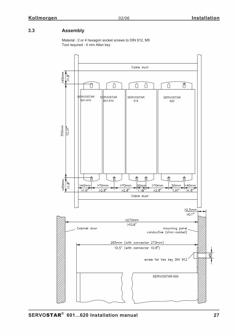
3.3 Assembly
Material : 2 or 4 hexagon socket screws to DIN 912, M5
Tool required : 4 mm Allen key - A.4.031.4/15
SERVOSTAR®
601...620 Installation manual 27
Kollmorgen 02/06 Installation
SERVOSTAR 600
SERVOSTAR
601-610SERVOSTAR
601-610
SERVOSTAR
614
SERVOSTAR
620
Page 28
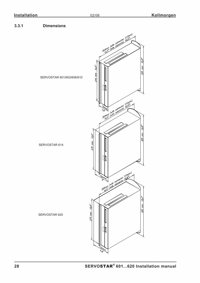
3.3.1 Dimensions
- A.4.031.4/14
28 SERVOSTAR®
601...620 Installation manual
Installation 02/06 Kollmorgen
SERVOSTAR 620
SERVOSTAR 601/603/606/610
SERVOSTAR 614
Page 29
3.4 Wiring
Only professional staff who are qualified in electrical engineering are allowed to
install the servo amplifier.
The installation procedure is described as an example. A different procedure may be sensible or
necessary, depending on the application of the equipment.
We provide further know-how through training courses (on request).
Warning !
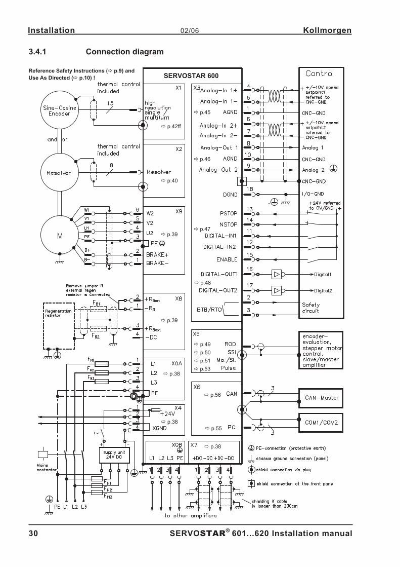
Only install and wire up the equipment when it is not live, i.e. when neither the
mains power supply nor the 24 V auxiliary voltage nor the operating voltages of
any other connected equipment is switched on.
Take care that the cabinet is safely disconnected (with a lock-out, warning signs
etc.). The individual voltages will be switched on for the first time during setup.
The ground symbol�, which you will find in all the wiring diagrams, indicates
that you must take care to provide an electrically conductive connection with the
largest possible surface area between the unit indicated and the mounting plate in
the switchgear cabinet.
This connection is for the effective grounding of HF interference, and must not be
confused with the PE- symbol � (a protective measure to EN 60204).
Use the following connection diagrams:
Overview : page 30
Multi-axis systems, example : page 29
Mains power : page 38
Motor : page 39
Feedback:
Resolver : page 40
Incr.Enc. or Sine Enc. with Hall : page 41
Encoder with EnDat/HIPERFACE : page 42
Incremental encoder (AqB) : page 43
Encoder without data channel : page 44
Encoder Emulation:
ROD (A quad B) : page 49
SSI : page 50
Master-Slave Interface : page 51
Pulse-Direction Interface : page 53
RS232 / PC : page 55
CAN Interface : page 56
Restart lock option -AS- : page 67
Expansion cards:
I/O-14/08 : page 73
PROFIBUS : page 74
SERCOS : page 76
DeviceNet : page 77
EtherCat : page 80
SynqNet : page 82
-2CAN- : page 84
SERVOSTAR®
601...620 Installation manual 29
Kollmorgen 02/06 Installation
Page 30
3.4.1 Connection diagram
- A.4.031.1/02
30 SERVOSTAR®
601...620 Installation manual
Installation 02/06 Kollmorgen
� p.55
� p.56
� p.38
� p.38
� p.39
� p.38
� p.39
� p.42ff
� p.40
� p.45
� p.46
� p.47
� p.48
� p.49
� p.50
� p.51
� p.53
SERVOSTAR 600Reference Safety Instructions (� p.9) and
Use As Directed (� p.10) !
Page 31
3.4.2 Example of connections for multi-axis system
- A.4.031.1/19
SERVOSTAR®
601...620 Installation manual 31
Kollmorgen 02/06 Installation
SERVOSTAR 600
SERVOSTAR 600
SERVOSTAR 600
Po
we
rsu
pp
ly
Reference Safety Instructions (� p.9) and
Use As Directed (� p.10) !
MM
M
Page 32
3.4.3 Pin assignments
- A.4.031.4/21
32 SERVOSTAR®
601...620 Installation manual
Installation 02/06 Kollmorgen
Page 33
3.4.4 Notes on connection techniques
3.4.4.1 Shielding connection to the front panel
- A.4.029.4/25
SERVOSTAR®
601...620 Installation manual 33
Kollmorgen 02/06 Installation
Remove the outer covering of the cable
and the shielding braid from the cores
for the required length. Secure the cores
with a cable tie.
Remove the outer covering of the cable
over a length of about 30mm, without
damaging the shielding braid.
Pull a cable tie through the slot in the
shielding rail (front panel) of the servo
amplifier.
Use the cable tie to clamp the shielding
braid of the cable firmly to the shielding
rail.
SERVOSTAR600
SERVOSTAR600
Page 34
3.4.4.2 Technical data for connecting cables
Further information on the chemical, mechanical and electrical characteristics of the cables can be
obtained from our customer service.
Observe the restrictions in the chapter "Conductor cross-sections" on page 20.
To reach the max. permitted cable length, you must use cable material that
matches the capacitance requirements listed below.
Insulation material
Sheathing PUR (polyurethane, code 11Y)
Core insulation PETP (polyesteraphtalate, code 12Y)
Capacitance
Motor cable less than 150 pF/m
RES-/Encoder-cable less than 120 pF/m
Technical data
— The brackets in the cable designation indicate the shielding.
— All cables are suitable for use as trailing cables.
— The technical data refer to the use as moveable cables.
— Operating life : 1 million bending cycles
Coresmax.
LengthUsed for
Operation-
Temperature range
Outside
diameter
Bending
radius
[mm²] [m] [°C] [mm] [mm]
(4x1.0) 100* Motor / power -30 / +80 10 100
(4x1.5) 100* Motor / power -30 / +80 10.5 105
(4x2.5) 100* Motor / power -5 / +70 12,6 125
(4x4) Power -5 / +70 14,7 150
(4x1,0+(2x0,75)) 100* Motor incl. Brake -30 / +80 10,5 105
(4x1,5+(2x0,75)) 100* Motor incl. Brake -30 / +80 11,5 120
(4x2,5+(2x1)) 100* Motor incl. Brake -30 / +80 14,2 145
(4x(2x0.25)) 100* Resolver -30 / +80 7,7 70
(7x(2x0,25)) 50* Encoder -30 / +80 9,9 90
* Motor cables longer than 25m with motor choke 3YLN only, see page 88.
Danaher Motion North America delivers cables up to 39m length.
* Danaher Motion Europe delivers cables up to the maximum length.
34 SERVOSTAR®
601...620 Installation manual
Installation 02/06 Kollmorgen
Page 35
3.5 Setup software
3.5.1 General
This chapter describes the installation of the setup software DRIVE.EXE for the SERVOSTAR 600
digital servo amplifiers.
We offer training and familiarization courses on request.
3.5.1.1 Use as directed
The setup software is intended to be used for setting up and storing the operating parameters for
the SERVOSTAR 600 series of servo amplifiers. The attached servo amplifier can be setup with the
assistance of the software - during this process the drive can be controlled directly by the service
functions.
Only professional personnel who have the relevant expertise described on page 7
are permitted to carry out online parameter setting for a drive which is running.
Sets of data which are stored on data media are not safe against unintended
alteration by other persons. After loading a set of data you must therefore check all
parameters
thoroughly before enabling the servo amplifier.
3.5.1.2 Software description
The servo amplifiers must be adapted to the requirements of your installation. Usually you will not
have to carry out this parameter setting yourself on the amplifier, but on a PC, with the assistance of
the setup software. The PC is connected to the servo amplifier by a null-modem cable (see p.55) .
The setup software provides the communication between SERVOSTAR 600 and the PC.
You will find the setup software on the accompanying CD-ROM and at our web site.
With very little effort you can alter parameters and instantly observe the effect on the drive, since
there is a continuous (online) connection to the amplifier.
Simultaneously, important actual values are read out from the amplifier and displayed on the PC
monitor (oscilloscope function).
Any interface modules (expansion cards) which may be built into the amplifier are automatically rec-
ognized, and the additional parameters which are required for position control or motion-block defi-
nition are made available.
Sets of data can be stored on data media (archived) and loaded again. Sets of data which are
stored on data media can be printed.
We supply you with motor-specific default sets of data for the most common combinations of servo
amplifier and motor. In most applications you will be able to use these default values to get your
drive running without any problems.
SERVOSTAR®
601...620 Installation manual 35
Kollmorgen 02/06 Installation
Page 36
3.5.1.3 Hardware requirements
The PC interface (X6, RS232) of the servo amplifier is connected to the serial interface of the PC by
a null-modem cable (not a null-modem link cable !) (� p.55).
Connect / disconnect the interface cable only when the supply is switched off for
both the PC and the servo amplifier.
The interface in the servo amplifier is electrically isolated by an optocoupler, and is at the same
potential as the CANopen interface.
Minimum requirements for the PC:
Processor : Pentium®
I or higher
Operating system : WINDOWS 95(c) / 98 / 2000 / ME / NT 4.0 / XP
Graphics adapter : Windows compatible, color
Drives : hard disk with at least 10 MB free space
CD-ROM drive
Main memory : at least 8MB
Interface : one free serial interface (COM1:, 2:, 3: or COM4:)
3.5.1.4 Operating systems
WINDOWS 95(c) / 98 / 2000 / ME / NT / XP
DRIVE.EXE is executable under WINDOWS 95(c) / 98 / 2000 / ME / XP and WINDOWS NT 4.0.
The HTML help system is not available under WINDOWS 95a and 95b.
WINDOWS FOR WORKGROUPS 3.xx, DOS, OS2 Unix, Linux
DRIVE.EXE is not executable under WINDOWS 3.xx, DOS, OS2, Unix and Linux.
In emergency, operation is possible through an ASCII terminal emulation (without user-interface).
Interface settings : 9600 bps, no parity, no handshake
3.5.2 Installation under WINDOWS 95 / 98 / 2000 / ME / NT / XP
An installation program can be found on the CD-ROM which makes it easier to install the setup soft-
ware on your PC.
Installation
Autostart function activated:
Insert the CD-ROM into a free drive. A window with the start screen opens. There you find a link to
the setup software DRIVE.EXE. Click it and follow the instructions.
Autostart function deactivated:
Insert the CD-ROM into a free drive. Click on START (task bar), then on Run. Enter the program
call: x:\start.exe (x = correct CD drive letter).
Click OK and proceed as described above.
Connection to the serial interface of the PC
Connect the interface cable to a serial interface on your PC and the PC interface (X6) of the
SERVOSTAR 600 (� p. 55).
36 SERVOSTAR®
601...620 Installation manual
Installation 02/06 Kollmorgen
Page 37
4 Interfaces
All important interfaces are shown in this Chapter. The precise location of the connectors and
terminals can be seen on page 32. The block diagram below is just an overview.
4.1 Block diagram
- A.4.031.1/47
SERVOSTAR®
601...620 Installation manual 37
Kollmorgen 02/06 Interfaces
Page 38
4.2 Power supply
4.2.1 Mains supply connection (X0)
— Directly to earthed (grounded) 3~ supply, integrated EMI filter
— Fusing (e.g. fusible cut-outs) provided by the user� p.19
4.2.2 24V auxiliary supply (X4)
— Electrically isolated, external 24VDC supply, e.g. with insulating transformer
— Required current rating� p.18
— Integrated EMI filter for the 24V auxiliary supply
4.2.3 DC bus link (X7)
Can be connected in parallel. A patented circuit distributes the regen power among all the amplifiers
connected to the same DC bus link circuit. (Connection example� p.31).
Only servo amplifiers with mains supply from the same mains (identical mains
supply voltage) may be connected by the DC bus link. - A.4.031.1/21,25
38 SERVOSTAR®
601...620 Installation manual
Interfaces 02/06 Kollmorgen
SERVOSTAR 600
SERVOSTAR 600
Page 39
4.3 Motor connection with brake (X9)
Lead length � 25m
Lead length >25m
For lead lengths above 25m the choke box 3YLN ( � p.88) must be wired into the motor
lead, close to the amplifier.
4.4 External regen resistor (X8)
Remove the plug-in link between the terminals X8/1 (-RB) and X8/2 (+Rbint).
- A.4.031.1/17,18
SERVOSTAR®
601...620 Installation manual 39
Kollmorgen 02/06 Interfaces
SERVOSTAR 600
SERVOSTAR 600
SERVOSTAR 600
Page 40
4.5 Feedback
Feedback system Conn. See Remarks
Resolver X2 p.40 2 to 36 poles
Incr. Encoder or Sine Encoder with Hall X1 p.41A, B, Zero, Hall oder Sinus,
Cosinus, Zero, Hall
Sine Encoder with EnDat/HIPERFACE X1 p.42 Sine, cosine, clock, data
Sine Encoder without data channel X1 p.44 Sine, cosine, Zero
Incremental encoder (A quad B) X5 p.43 A, B, Zero
4.5.1 Resolver (X2)
Our rotatory servomotors have 2-pole hollow-shaft resolvers built in as a standard. It is possible to
connect 2...36-pole resolvers to the SERVOSTAR 600.
If lead lengths of more than 100m are planned, please contact our customer service.
The thermostat contact in the motor is connected via the resolver cable to the SERVOSTAR 600
and evaluated there. - A.4.031.1/26
40 SERVOSTAR®
601...620 Installation manual
Interfaces 02/06 Kollmorgen
SERVOSTAR 600 SubD9 12pol.round
Page 41
4.5.2 Incremental encoder / sine encoder with Hall (X1)
Encoder types (incremental or sine/cosine) that do not provide definitive information on commuta-
tion, can be used as a complete feedback system using an additional Hall dongle. In this case, an
adapter is used for interfacing and adapting the signals (Hall dongle, p� p. 90). This adapter is
also used to connect encoders known as ComCoders.
If you plan to use a cable longer than 25m, please contact our application department.
Encoder types with a power consumption of more than 150mA can also be connected using our
external power supply (� p. 89).
For encoders that do not have integrated terminating resistors, we offer an optional terminating
adapter (� p. 89)
Frequency limit (A, B): 250 kHz.
SERVOSTAR®
601...620 Installation manual 41
Kollmorgen 02/06 Interfaces
SERVOSTAR 600
Page 42
4.5.3 Sine Encoder with EnDat or HIPERFACE (X1)
As an option, our servomotors can be fit with a single-turn or multiturn sine-cosine encoder. Pre-
ferred types are ECN1313 and EQN1325.
This encoder is used by the SERVOSTAR 600 as a feedback device for drive tasks which require
highly precise positioning or extremely smooth running.
If lead lengths of more than 50m are planned, please consult our customer service.
The thermostat contact in the motor is connected via the encoder cable to the SERVOSTAR 600
and evaluated there.
Encoder types with a power consumption of more than 150mA can also be connected using our
external power supply (� p. 89). For encoders that do not have integrated terminating resistors, we
offer an optional terminating adapter (� p. 89).
Frequency limit (A, B): 250 kHz. - A.4.031.1/27
42 SERVOSTAR®
601...620 Installation manual
Interfaces 02/06 Kollmorgen
SERVOSTAR 600SubD1 17pol.round
Page 43
4.5.4 Incremental Encoder (X5)
An incremental encoder can be used as standard motor feedback.
Select feedback type 8 "RS422 5V with W&S". Drive executes wake&shake to calculate the neces-
sary start-up information for the position controller every time the 24V auxiliary voltage is switched
on.
If lead lengths of more than 50m are planned and for questions concerning the power supply of the
encoder, please consult our customer service.
The thermostat contact in the motor is connected to X1 (see p.42) or X2 (see p.40). AGND and
DGND (connector X3) must be joined together !
Frequency limit: 1.5 MHz
Don't use this feedback type with vertical load (hanging load).
SERVOSTAR®
601...620 Installation manual 43
Kollmorgen 02/06 Interfaces
SERVOSTAR 600 SubD 9
Page 44
4.5.5 Sine Encoder without data channel (X1)
A sine-cosine encoder without data channel can be used as standard motor feedback. Select feed-
back type 7 "SinCos 5V with W&S". Drive executes wake&shake to calculate the necessary start-up
information for the position controller every time the 24V auxiliary voltage is switched on.
The thermostat contact in the motor is connected via the encoder cable to X1 and evaluated there.
If lead lengths of more than 50m are planned, please consult our customer service. Encoder types
with a power consumption of more than 150mA can also be connected using our external power
supply (� p. 89).
For encoders that do not have integrated terminating resistors, we offer an optional terminating
adapter (� p. 89).
Frequency limit (A, B): 250 kHz
Don't use this feedback type with vertical load (hanging load).
44 SERVOSTAR®
601...620 Installation manual
Interfaces 02/06 Kollmorgen
SERVOSTAR 600
Page 45
4.6 Digital and analog inputs and outputs
4.6.1 Analog inputs (X3)
The servo amplifier is equipped with two differential inputs for analog setpoints which are
programmable. AGND (X3/1) must always be joined to the CNC-GND of the controls as a ground
reference.
Technical characteristics
— Differential-input voltage max. � 10 V
— Resolution 1.25 mV
— Ground reference AGND, terminal X3/1
— Input resistance 20 k�
— Common-mode voltage range for both inputs ± 10 V
— Update rate 62,5 µs
Input Analog-In 1 (terminals X3/4-5)
Differential input voltage max. ± 10 V, resolution 14-bit, scalable
Standard setting : speed setpoint
Input Analog-In 2 (terminals X3/6-7)
Differential input voltage max. ± 10 V, resolution 12-bit, scalable
Standard setting : torque setpoint
Application examples for setpoint input Analog-In 2:
— adjustable external current limit
— reduced-sensitivity input for setting-up/jog operation
— pre-control / override
Fixing the direction of rotation
Standard setting : clockwise rotation of the motor shaft (looking at the shaft end)
— Positive voltage between terminal X3/4 (+ ) and terminal X3/5 ( - ) or
— Positive voltage between terminal X3/6 (+ ) and terminal X3/7 ( - )
To reverse the direction of rotation, swap the connections to terminals X3/4-5 and. X3/6-7 or
change the ROT. DIRECTION parameter in the “Speed controller” screen. - A.4.031.1/23
SERVOSTAR®
601...620 Installation manual 45
Kollmorgen 02/06 Interfaces
SERVOSTAR 600
Page 46
4.6.2 Analog outputs (X3)
Technical characteristics
— Reference ground is analog-GND (AGND, terminal X3/1 and X3/10)
— Output resistance 2.2 k�
— Output voltage �10 V
— Resolution 10 bit.
— Update rate 62,5 µs
Programmable analog outputs Analog-Out 1 / Analog-Out 2
The terminals X3/8 (Analog-Out 1) or X3/9 (Analog-Out 2) can have the following analog signals
assigned to them:
Standard setting :
Analog-Out 1 : Tachometer voltage nact (speed)
The output delivers �10V at the preset limit speed.
Analog-Out 2 : Current actual value Iact (torque)
The output delivers � 10V at the preset peak current Ipeak (effective r.m.s. value).
You can use the terminals X3/8 (Analog-Out 1) or X3/9 (Analog-Out 2) to output converted analog
values for digital measurements which are contained in the servo amplifier.
You can find a list of pre-programmed functions on the "Analog I/O" screen of our setup software. -A.031.1/22
46 SERVOSTAR®
601...620 Installation manual
Interfaces 02/06 Kollmorgen
SERVOSTAR 600
Page 47
4.6.3 Digital inputs (X3)
All digital inputs are electrically isolated through optocouplers.
Technical characteristics
— Reference ground is digital-GND (DGND, terminal X3/18)
— Inputs at X3 meet PLC standards (IEC 61131-2 Type 1)
— High: 11...30V / 2...11mA, Low -3...5V / <1 mA
— Update rate: 250µs
ENABLE input
The output stage of the servo amplifier is activated by the enable signal
(terminal X3/15, input 24V, active-high).
In the inhibited state (low signal) the motor which is attached does not have any torque.
Programmable digital inputs :
You can use the digital inputs PSTOP / NSTOP / DIGITAL-IN1 and DIGITAL-IN2 to initiate
preprogrammed functions that are stored in the servo amplifier.
You can find a list of pre-programmed functions on the "digital I/O" screen of our setup software.
If an input is freshly assigned to a pre-programmed function, then the data set must be stored in the
EEPROM of the servo amplifier, and the 24V auxiliary supply of the servo amplifier must be
switched off and on again (to reset the amplifier software).
Limit-switches PSTOP / NSTOP
Terminals X3/13 and X3/14 are normally programmed for the connection of limit switches. If these
inputs are not needed for the connection of limit switches, then they are programmable for other
input functions.
Limit-switch positive/negative (PSTOP / NSTOP, terminals X3/13 and X3/14), high level in normal
operation (fail-safe for a cable break).
A low signal (open) inhibits the corresponding direction of rotation, the ramp function remains
effective.
DIGITAL-IN 1 / DIGITAL-IN 2
The digital inputs on terminal X3/11 (DIGITAL-IN 1) or terminal X3/12 (DIGITAL-IN 2) can be logi-
cally combined in a pre-programmed function. - A.4.031.1/24
SERVOSTAR®
601...620 Installation manual 47
Kollmorgen 02/06 Interfaces
SERVOSTAR 600
Page 48
4.6.4 Digital outputs (X3)
Technical characteristics
— Reference ground is digital-GND (DGND, terminal X3/18)
— All digital outputs are floating
— DIGITAL-OUT1 and 2 : Open-Collector, max. 30V DC, 10mA
BTB/RTO : Relay output, max. 30VDC or 42VAC, 0.5A
— Update rate : 250 µs
Ready-to-operate contact BTB/RTO
Operational readiness (terminals X3/2 and X3/3 ) is signaled by a floating relay contact.
The contact is closed when the servo amplifier is ready for operation, the signal is not influenced
by the enable signal, the I²t- limit, or the regen threshold.
All faults cause the BTB/RTO contact to open and the switch-off of the output
stage (if the BTB contact is open, the output stage is disabled -> no power).
A list of the error messages can be found on page 62.
Programmable digital outputs DIGITAL-OUT 1 / 2:
You can use the digital outputs DIGITAL-OUT1 (terminal X3/16) and DIGITAL-OUT2 (terminal
X3/17) to output messages from pre-programmed functions that are stored in the servo amplifier.
You can find a list of pre-programmed functions on the "digital I/O" screen of our setup software.
If an input is freshly assigned to a pre-programmed function, then the data set must be stored in the
EEPROM of the servo amplifier, and the 24V auxiliary supply of the servo amplifier must be
switched off and on again (to reset the amplifier software).
Evaluate the outputs via inverting interface relays (see connection diagram), for example
Phönix DEK-REL-24/I/1 (turn-on delay 6 ms, turn-off delay 16ms).
The described logic in the SETUP SOFTWARE manual and the online help refers to
the output of the inverting interface relays. Consider the delay of the applied relay !- A.4.031.1/20
48 SERVOSTAR®
601...620 Installation manual
Interfaces 02/06 Kollmorgen
SERVOSTAR 600
Page 49
4.7 Encoder emulations
4.7.1 Incremental encoder output - A quad B (X5)
The incremental-encoder interface is part of the package supplied. Select the encoder function
ROD (screen page “Encoder”). In the servo amplifier, the position of the motor shaft is calculated
from the cyclic-absolute signals of the resolver or encoder. Incremental-encoder compatible pulses
are generated from this information. Pulses are output on the SubD-connector X5 as two signals, A
and B, with 90° phase difference and a zero pulse.
The resolution (lines before quadrature) can be changed with the RESOLUTION parameter:
Encoder function
(ENCMODE)Feedback system Resolution Zero position
ROD (1)
Resolver 16...1024one per revolution
(only if A=B=1)
EnDat / HIPERFACE16...4096 and
8192...524288 (2n)
one per revolution
(only if A=B=1)
ROD interpolation (3)Incremental encoders with-
out absolute data channel
4...128
TTL lines per sine line
analog pass through
from X1 to X5
You can also adjust and store the position of the zero pulse within one mechanical turn
(parameter NI-OFFSET).
The drivers are supplied from an internal supply voltage. PGND must always be
connected to the controls. The max. admissible cable length is 10 m.
Connections and signal description for incremental-encoder interface :
Default count direction: upwards when the motor shaft is rotating clockwise (looking at the shaft
end). - A.4.031.1/11
SERVOSTAR®
601...620 Installation manual 49
Kollmorgen 02/06 Interfaces
SERVOSTAR 600
Page 50
4.7.2 SSI output (X5)
The SSI interface (synchronous serial absolute-encoder simulation) is part of the delivered pack-
age. Select the encoder function SSI (screen page “Encoder”). In the servo amplifier, the position of
the motor shaft is calculated from the cyclically absolute signals from the resolver or encoder. This
information is used to create a position output in a format that is compatible with the standard
SSI-absolute-encoder format. 24 bits are transmitted.
SINGLE TURN selected: The upper 12 bits are fixed to ZERO, the lower 12 bits contain the posi-
tion information. For 2-pole resolvers, the position value refers to the position within one turn of the
motor, for 4-pole resolvers it is within half a turn, and for 6-pole resolvers it is within a third of a turn.
Exception: If an encoder with a commutation track is used as the feedback unit, then the upper 12
bits are set to 1 (data invalid!) until a homing run is performed.
MULTI TURN selected: The upper 12 bits contain the number of motor turns, the lower 12 bits con-
tain the position information.
The signal sequence can be output in Gray code (standard) or in binary code (parameter
SSI-CODE). The servo amplifier can be adjusted to the clock frequency of your SSI-evaluation with
the SSI-TAKT parameter (200 kHz or 1.5MHz and inverted).
Drivers are supplied from internal supply voltage.
PGND must always be connected.
Connection and signal description for SSI interface :
Default count direction: upwards when the motor shaft is rotating clockwise (looking at the shaft
end). - A.4.031.1/12
50 SERVOSTAR®
601...620 Installation manual
Interfaces 02/06 Kollmorgen
SERVOSTAR 600
Page 51
4.8 Master-slave operation, encoder master control
This interface can be used to link several SERVOSTAR 600 amplifiers together in master-slave
operation.
The parameters for the slave amplifiers are set up with the aid of the setup software.
The resolution (no. of pulses/turn) can be adjusted. The analog setpoint inputs are out of action.
AGND and DGND (connector X3) must be joined together !
Signal diagram (for encoders with RS422 or 24V output)
4.8.1 Connection to a SERVOSTAR master, 5V signal level (X5)
This interface can be used to link several SERVOSTAR amplifiers together in master-slave opera-
tion. Up to 16 slave amplifiers can be controlled by the master via the encoder output. The connec-
tor X5 must be used.
Frequency limit: 1,5MHz, slew rate tv � 0,1µs
AGND and DGND (connector X3) must be joined together ! - A.4.031.1/16,3/2
SERVOSTAR®
601...620 Installation manual 51
Kollmorgen 02/06 Interfaces
SERVOSTAR 600
SERVOSTAR 600
Page 52
4.8.2 Connection to encoders with 24V signal level (X3)
This interface can be used to operate the SERVOSTAR as a slave, mastered by an encoder with
24V signal level (master-slave operation). The digital inputs DIGITAL-IN 1 and 2 at connector X3
must be used. Frequency limit: 250 kHz, slew rate tv � 0,1µs
AGND and DGND (connector X3) must be joined together !
4.8.3 Connection to a sine-cosine encoder (X1)
This interface can be used to operate the SERVOSTAR as a slave, mastered by a sine-cosine
encoder (master-slave operation). The connector X1 must be used. Encoder types with a power
consumption of more than 150mA can also be connected using our external power supply (� p.89).
For encoders that do not have integrated terminating resistors, we offer an optional terminating
adapter (� p. 89). Frequency limit: 250 kHz
AGND and DGND (connector X3) must be joined together ! - A.4.031.1/44,43
52 SERVOSTAR®
601...620 Installation manual
Interfaces 02/06 Kollmorgen
SERVOSTAR 600
SERVOSTAR 600
Page 53
4.9 Interface for stepper-motor controls (pulse-direction)
This interface can be used to connect the servo amplifier to a third-party stepper-motor controller.
The parameters for the servo amplifier are set up with the aid of the setup software (electrical gear-
ing). The number of steps can be adjusted, so that the servo amplifier can be adjusted to the
pulse-direction signals of any stepper-motor controller. Various monitoring signals can be output.
The analog setpoint inputs are out of action.
AGND and DGND (connector X3) must be joined together! Observe the frequency
limit!
Speed profile and signal diagram
Encoder Input A quad B offers more EMI suppression. - A.4.031.3/2
SERVOSTAR®
601...620 Installation manual 53
Kollmorgen 02/06 Interfaces
Page 54
4.9.1 Connection to stepper-motor controller with 5V signal level (X5)
This interface can be used to connect the servo amplifier to a stepper-motor controller with 5V
signal level. The connector X5 must be used.
Frequency limit: 1,5MHz
AGND and DGND (connector X3) must be joined together !
4.9.2 Connection to stepper-motor controller with 24V signal level (X3)
This interface can be used to connect the servo amplifier to a stepper-motor controller with 24V
signal level. The digital inputs DIGITAL-IN 1 and 2 at connector X3 must be used.
Frequency limit: 250 kHz
AGND and DGND (connector X3) must be joined together ! - A.4.031.1/10,45
54 SERVOSTAR®
601...620 Installation manual
Interfaces 02/06 Kollmorgen
SERVOSTAR 600
SERVOSTAR 600
Page 55
4.10 RS232 interface, PC connection (X6)
The setting of the operating, position control, and motion-block parameters can be carried out with
an ordinary commercial PC.
Connect the PC interface (X6) of the servo amplifier while the supply to the equipment is
switched off via a normal commercial 3-core null-modem cable to a serial interface on the PC.
Do not use a null-modem link cable!
The interface is electrically isolated through an optocoupler, and is at the same potential as the
CANopen interface.
The interface is selected and set up in the setup software.
Further notes can be found on page 35.
With the optional expansion card -2CAN- the two interfaces for RS232 and CAN, which otherwise
use the same connector X6, are separated onto two connectors (� p.83).
Interface cable between the PC and servo amplifiers of the SERVOSTAR 600 series:
(View : looking at the face of the built-in SubD connectors, this corresponds to the solder side of the
SubD sockets on the cable) - A.4.031.1/13,14
SERVOSTAR®
601...620 Installation manual 55
Kollmorgen 02/06 Interfaces
SERVOSTAR 600
Page 56
4.11 CANopen Interface (X6)
The interface for connection to the CAN bus (default 500 kBaud). The integrated profile is based on
the communication profile CANopen DS301 and the drive profile DS402. The following functions are
available in connection with the integrated position controller:
Jogging with variable speed, reference traverse (zeroing), start motion task, start direct task, digital
setpoint provision, data transmission functions and many others.
Detailed information can be found in the CANopen manual. The interface is electrically isolated by
optocouplers, and is at the same potential as the RS232 interface. The analog setpoint inputs can
still be used.
With the optional expansion card -2CAN- the two interfaces for RS232 and CAN, which otherwise
use the same connector X6, are separated onto two connectors� p.83).
AGND and DGND (connector X3) must be joined together !
CAN bus cable
To meet ISO 11898 you should use a bus cable with a characteristic impedance of 120 �. The
maximum usable cable length for reliable communication decreases with increasing transmission
speed. As a guide, you can use the following values which we have measured, but they are not to
be taken as assured limits:
Cable data: Characteristic impedance 100-120 �
Cable capacitance max. 60 nF/km
Lead resistance (loop) 159.8 �/km
Cable length, depending on the transmission rate
Transmission rate
(kbaud)max. cable length (m)
1000 20
500 70
250 115
Lower cable capacitance (max. 30 nF/km) and lower lead resistance
(loop, 115 �/km) make it possible to achieve greater distances.
(Characteristic impedance 150 ± 5� � terminating resistor 150 ± 5�).
For EMC reasons, the SubD connector housing must fulfill the following conditions:
— metal or metallised housing
— provision for cable shielding connection in housing, large-area connection -A.4.031.1/15, 1/36
56 SERVOSTAR®
601...620 Installation manual
Interfaces 02/06 Kollmorgen
SERVOSTAR 600
Page 57
5 Setup
5.1 Important notes
Only professional personnel with extensive knowledge in the fields of electrical/
drive technology are allowed to setup the servo amplifier.
The procedure for setup is described as an example. Depending on the application,
a different procedure may be sensible or necessary. In multi-axis systems, setup each servo ampli-
fier individually.
The manufacturer of the machine must generate a hazard analysis for the machine,
and take appropriate measures to ensure that unforeseen movements cannot
cause injury or damage to any person or property.
Check that all live connecting elements are protected from accidental contact.
Deadly voltages can be present, up to 900V.
Never disconnect any of the electrical connections to the servo amplifier while it is
live. Capacitors can still have residual charges with dangerous levels up to 300
seconds after switching off the supply power.
Heat sinks and front panels of the amplifier can reach a temperature of up to
80°C(176°F) in operation. Check (measure) the heat sink temperature. Wait until the
heat sink has cooled down below 40°C (104°F) before touching it.
If the servo amplifier has been stored for longer than 1 year, then the DC bus link
capacitors will have to be re-formed.
To do this, disconnect all the electrical connections.
Supply the servo amplifier for about 30 min. from single-phase 230VAC to the
terminals L1 / L2. This will re-form the capacitors.
Further information on setup :
The adaptation of parameters and the effects on the control loop behavior are
described in the manual for the setup software and in the online help of the setup
software.
The setup of the expansion card (if present) is described in the corresponding
manual on the CD-ROM.
We can provide further know-how through training courses (on request).
SERVOSTAR®
601...620 Installation manual 57
Kollmorgen 02/06 Setup
Page 58
5.2 Guide to Setup
The following instructions should help you to carry out the setup in a sensible order, without any
hazards to people or machinery.
Check installation � p.25ff. Disconnect the servo amplifier from the supply.
Inhibit
Enable signal0V on terminal X3/15 (Enable)
Switch on 24V
auxiliary voltage
24VDC on terminal X4/1, ground on terminal X4/3
After the initialisation procedure (about 0.5 sec.) the status is
shown in the LED display (� p.61)
Switch on PC,
start setup software
Select the interface to which the servo amplifier is connected,
The parameters which are stored in the SRAM of the servo
amplifier are transferred to the PC.
Check displayed
parameters,
and correct
if necessary
It is important to check the following parameters.
If you do not keep to them, parts of the system can be
damaged or destroyed.
Supply voltage:
Rated motor voltage:
Motor pole-no:
Feedback:
IRMS:
IPEAK:
Limit speed:
Regen power:
Station address:
set to the actual mains supply voltage
at least as high as the DC bus link voltage of the amplifier
must match the motor (see motor manual)
must match the feedback unit in the motor
maximum is the motor standstill current I0 (on nameplate)
maximum is 4 x motor standstill current I0
maximum is the rated motor speed (on nameplate)
maximum is the permitted regen resistor dissipation
unique address (see setup software manual)
Check
safety devices
Make sure that any unintended movement of the drive
cannot cause danger to machinery or personnel.
Switch on
supply powerthrough the ON/OFF button of the contactor control
Apply 0V setpoint 0V on terminals X3/4-5 or X3/6-7
Enable(500 ms after switching on the supply power) 24VDC on
terminal X3/15, motor stands with standstill torque M0
Setpointapply a small analog setpoint, about 0.5V is recommended,
to terminals X3/4-5 or X3/6-7
If the motor oscillates, the parameter Kp in the menu
page “speed controller” must be reduced.
- the motor is endangered!
Optimization Optimize speed, current and position controllers
Setup
the expansion card
see setup instructions in the corresponding
manual on the CD-ROM
58 SERVOSTAR®
601...620 Installation manual
Setup 02/06 Kollmorgen
Page 59
5.3 Parameter setting
A default parameter set is loaded into your servo amplifier by the manufacturer. This contains valid
and safe parameters for the current and speed controllers.
A database for motor parameters is stored in the servo amplifier. During setup you must select the
data set for the motor that is connected and store it in the servo amplifier. For most applications
these settings will already provide good to very good control loop characteristics.
An exact description of all parameters and the possibilities for optimizing the control loop character-
istics can be found in the manual “Setup Software DRIVE.EXE”.
5.3.1 Multi-axis systems
Using a special multilink cable, you can connect up to six servo amplifiers together and to your PC :
Cable type -SR6Y- (for 4 amplifiers) or -SR6Y6- (for 6 amplifiers)
With the PC connected to just one servo amplifier you can now use the setup software to select all
four / six amplifiers through the preset station addresses and set up the parameters.
5.3.1.1 Node address for CAN-bus
During setup it makes sense to preset the station addresses for the individual amplifiers and the
baud rate for communication by means of the keypad on the front panel (� p.61).
5.3.1.2 Baud rate for CAN-bus
After changing the station address and baud rate you must turn the 24V auxiliary
supply of the servo amplifier off and on again.
Coding of the baud rate in the LED display :
Coding Baud rate in kbit/s Coding Baud rate in kbit/s
0 10 5 250
1 20 6 333
2 50 7 500
3 100 8 666
4 125 9 800
10 1000
- A.4.031.4/37
SERVOSTAR®
601...620 Installation manual 59
Kollmorgen 02/06 Setup
PC
Add.:
01
Add.:
02
Add.:
03
Add.:
04
COMx
RS232
Cable -SR6Y-
X6
PC/CAN
X6
CAN
X6
CAN
X6
CAN
Baud rate identical for all amplifiers,
see table below
Page 60
5.3.2 Key operation / LED display
In this chapter the two possible operation menus and the use of the keys in the front panel are
shown. Normally, the SERVOSTAR 600 only places the standard menu at your disposal. If you
want to attend the amplifier via the detailed menu, you must keep the right key pressed while
switching on the 24V-supply.
5.3.2.1 Key operation
The two keys can be used to perform the following functions:
Key symbol Functions
press once : go up one menu item, increase number by one
press twice in rapid succession : increase number by ten
press once : go down one menu item, decrease number by one
press twice in rapid succession : decrease number by ten
press and hold right key, then press left key as well :
enter a number, return function name
5.3.2.2 Status display
- A.4.031.3/4
60 SERVOSTAR®
601...620 Installation manual
Setup 02/06 Kollmorgen
Page 61
5.3.2.3 Standard menu structure
5.3.2.4 Extended menu structure
- A.4.031.3/3
SERVOSTAR®
601...620 Installation manual 61
Kollmorgen 02/06 Setup
� p.59
� p.59
� p.59
Page 62
5.4 Error messages
Errors which occur are shown in coded form by an error number in the LED display on the front
panel. All error messages result in the BTB/RTO contact being opened, and the output stage of the
amplifier being switched off (motor loses all torque). If a motor-holding brake is installed, it will be
activated.
Number Designation Explanation
E / S / A / P Status Messages Status messages, no error, see p. 60
. . . Status Message updating the startup configuration
F01* heat sink temperatureheat sink temperature too high
limit is set by manufacturer to 80°C (176°F)
F02* overvoltageovervoltage in DC bus link
limit depends on the mains supply voltage
F03* following error message from the position controller
F04 feedback cable break, short circuit, short to ground
F05* undervoltageundervoltage in DC bus link
limit is set by manufacturer to 100V
F06 motor temperaturemotor temperature too high
limit is set by manufacturer to145°C (293°F)
F07 aux. voltage internal aux. voltage not OK
F08* overspeed motor running away, speed is too high
F09 EEPROM checksum error
F10 Flash-EPROM checksum error
F11 brake cable break, short circuit, short to ground
F12 motor phase motor phase missing (cable break or similar)
F13* internal temperature internal temperature too high
F14 output stage fault in the output stage
F15 I²t max I²t max. value exceeded
F16* supply - BTB/RTO 2 or 3 phases missing in the supply feed
F17 A/D convertererror in the analog-digital conversion, usually caused by ex-
cessive EMI
F18 regen regen circuit faulty or incorrect setting
F19* supply phasea supply phase is missing
(can be switched off for 2-phase operation)
F20 Slot fault Hardware fault of the expansion card
F21 Handling fault Software fault of the expansion card
F22Short circuit to earth
(ground)SERVOSTAR 640/670 only: short circuit to earth (ground)
F23 CAN Bus off CAN Bus total communication error
F24 Warning Warning displays as error
F25 Commutation error Encoder systems only
F26 Limit switch Homing error (hardware limit switch reached)
F27 AS-optionoperational error with -AS- option, input for AS-Enable and
ENABLE have been set at the same time
F28 reserved reserved
F29 Fieldbus-Sync Fieldbus not synchronized
F30 Emerg. Stop Timeout Emerg. Stop Timeout
F31 reserved reserved
F32 System error system software not responding correctly
* = These error messages can be cancelled by the ASCII command CLRFAULT, without executing a reset. If
only these errors are present, and the RESET button or the I/O-function RESET is used, the CLRFAULT com-
mand is also all that is carried out.
More information about faults and hints for removal can be found on page 92
62 SERVOSTAR®
601...620 Installation manual
Setup 02/06 Kollmorgen
Page 63
5.5 Warning messages
Faults which occur, but which do not cause a switch-off of the amplifier output stage (BTB/RTO con-
tact remains closed), are indicated in the LED display on the front panel by a coded warning
number.
Number Designation Explanation
E / S / A / P Status Messages Status messages, no error, see p. 60
. . . Status Message updating the startup configuration
n01 I²t I²t threshold exceeded
n02 regen power reached preset regen power limit
n03* S_fault exceeded preset following error limit
n04* response monitoring response monitoring (fieldbus) has been activated
n05 supply phase Mains supply phase missing
n06* Sw limit switch 1 passed software limit switch 1
n07* Sw limit switch 2 passed software limit switch 2
n08 motion task error a faulty motion task was started
n09 no reference point no reference point (Home) set at start of motion task
n10* PSTOP PSTOP limit-switch activated
n11* NSTOP NSTOP limit-switch activated
n12motor default values
loaded
only for ENDAT or HIPERFACE® :
discrepancy between motor number saved in the encoder
and the amplifier, motor default values loaded
n13* expansion card expansion card not operating correctly
n14 SinCos feedback
SinCos commutation (wake & shake) not completed, will
be canceled when amplifier is enabled and wake & shake
carried out
n15 table error fault according to speed/current table INXMODE 35
n16 Summarized warning Summarized warning for n17 to n31
n17 Fieldbus-Sync Fieldbus not synchronized
n18 Multiturn overflow Max. number of motor turns exceeded
n19-n31 reserved reserved
n32 firmware beta version firmware is an unreleased beta version
A reset RESET is present on input DIGITAL INx
* = These warning messages lead to a controlled shut-down of the drive (braking with the emergency ramp)
More information about faults and hints for removal can be found on page 92
SERVOSTAR®
601...620 Installation manual 63
Kollmorgen 02/06 Setup
Page 64
This page has been deliberately left blank.
64 SERVOSTAR®
601...620 Installation manual
Setup 02/06 Kollmorgen
Page 65
6 Expansions / Accessories
6.1 Option -AS-, restart lock for personal safety
6.1.1 Advantages of the -AS- option
A frequently required application task is the protection of personnel against the restarting of drives.
This can not be achieved by an electronic inhibit, but must be implemented with mechanical ele-
ments (positively driven relay contacts).
To get round this problem, up to now either the main contactor in the mains supply line was
switched off, or another contactor was used to disconnect the motor from the servo amplifier.
The disadvantages of this method are :
— the DC bus link has to be charged up again at restart
— wear on the contacts of the contactors, caused by switching under load
— extensive wiring required, with additional switching components
The -AS- option avoids these disadvantages. A safety relay in the servo amplifier is activated either
by the PLC or manually. Positively driven contacts provide a safe disconnection of the servo ampli-
fier, the setpoint input of the servo amplifier is inhibited, and a signal is sent to the safety circuit.
The suggested circuits (� p. 68) fulfills safety category 1 (EN 954-1). You can fulfill safety category
3, if you use a mains contactor with suited supervision.
Advantages of the -AS- option :
— the DC bus link remains charged up, since the mains supply line remains active
— only low voltages are switched, so there is no contact wear
— very little wiring is required
— the functionality and the personnel safety when using the circuit recommendations
in this documentation have been approved by the Trade Liability Association.
6.1.2 Functional description
An additional connector (X10) is mounted on the front panel of the SERVOSTAR 600. The coil con-
nections and a make (n.o.) contact of a safety relay are made available through 4 terminals on this
connector.
The 24VDC safety relay in the servo amplifier (approved) is controlled externally. All the relay con-
tacts have positive action.
Two contacts switch off the driver supply of the output stage in the servo amplifier, and short the
internal setpoint signal to AGND (0 V).
The make (n.o.) contact used for monitoring is looped into the control circuit.
If the safety relay is not energized, then the monitoring contact is open and the servo amplifier is
ready for operation.
If the drive is electronically braked, the servo amplifier is disabled and the motor-holding brake is
on, then the safety relay is energized (manually or by the controls).
The supply voltage for the driver circuit of the output stage is switched off in a safe manner, the
internal setpoint is shorted to 0V, and the monitoring contact bridges the safety logic in the control
circuit of the system (monitoring of protective doors etc.)
Even if the output stage or driver is destroyed, it is impossible to start the motor.
If the safety relay itself is faulty, then the monitoring contact cannot bridge the safety logic of the
system. Opening the protective devices will then switch off the system.
SERVOSTAR®
601...620 Installation manual 65
Kollmorgen 02/06 Expansions / Accessories
Page 66
6.1.3 Block diagram
6.1.4 Signal diagram (sequence)
- A.4.031.1/32,30
66 SERVOSTAR®
601...620 Installation manual
Expansions / Accessories 02/06 Kollmorgen
Page 67
6.1.5 Installation / Setup
6.1.5.1 Safety instructions
� Observe "Use as directed" on page 10.
� The monitoring contacts (KSO1/2) for each amplifier with an -AS- option must be
looped into the control circuit. This is vital, so that a malfunction of the internal safety
relay or a cable break can be recognized.
� If the -AS- option is automatically activated by a control system (KSI1/2), then make
sure that the output of the control is monitored for possible malfunction. This can be
used to prevent a faulty output from activating the -AS- option while the motor is run-
ning.
� It is vital to keep to the following functional sequence when the -AS- option is used:
1. Brake the drive in a controlled manner (speed setpoint = 0V)
2. When speed = 0 rpm, disable the servo amplifier (enable = 0V)
3. If there is a suspended load, apply an additional mechanical block to the drive
4. Activate the -AS- option
6.1.5.2 Functional test
The functioning of the restart lock must be tested during setup, after every alteration in the wiring of
the system, or after exchanging one or more components of the system.
1. Stop all drives, with setpoint 0V, disable drives,
mechanically block any suspended loads
2. Activate the -AS- option.
3. Open protective screens (but do not enter hazardous area)
4. Pull off the X10 connector from an amplifier: the mains contactor must drop out
5. Reconnect X10. Switch on mains contactor again.
6. Repeat steps 4 and 5 for each individual servo amplifier.
6.1.5.3 Connection diagram
- A.4.031.1/30
SERVOSTAR®
601...620 Installation manual 67
Kollmorgen 02/06 Expansions / Accessories
SERVOSTAR 600
Page 68
6.1.6 Application examples
6.1.6.1 Moving single axes or axis-groups in setting-up operation
In setting-up operation, people will frequently be within the danger zone of the machinery. Axes will
normally be moved under the control of permission switches. An additional switch-off of the unused
axes, by means of the restart lock, increases the safety margin and avoids the repeated switching
of main contactors or motor contactors.
6.1.6.2 Switching off grouped axes with separate working areas
Even when several SERVOSTAR 600 are operating off a common mains supply and DC bus link, it
is possible to set up groups for separate working areas. These groups can then be switched off sep-
arately for personnel safety. For this purpose, we have provided you with a suggested circuit (mains
supply circuit and control circuit for 2 separate working groups which have interconnected DC bus
links and a common mains supply voltage).
6.1.6.2.1 Control circuit
The suggested circuit fulfills safety category 1 (EN 954-1). You can fulfill safety category 3, if you
use a mains contactor with suited supervision. - A.4.031.1/311
68 SERVOSTAR®
601...620 Installation manual
Expansions / Accessories 02/06 Kollmorgen
Page 69
6.1.6.2.2 Mains supply circuit
- A.4.031.3/05
SERVOSTAR®
601...620 Installation manual 69
Kollmorgen 02/06 Expansions / Accessories
SERVOSTAR SERVOSTAR SERVOSTAR SERVOSTAR SERVOSTAR
Page 70
6.2 Expansion Cards
Information about availability and order numbers can be found on p. 96
6.2.1 Guide to installation of expansion cards
� Use a suitable screwdriver to lever off the cover of the option slot.
� Take care that no small items (such as screws) fall into the open option slot.
� Push the expansion card carefully into the provided guide rails of the slot, without
twisting it.
� Press the expansion card firmly into the slot, until the front cover touches the fixing
lugs. This ensures that the connectors make good contact.
� Screw the screws on the front cover into the threads in the fixing lugs.
70 SERVOSTAR®
601...620 Installation manual
Expansions / Accessories 02/06 Kollmorgen
Page 71
6.2.2 Expansion card -I/O-14/08-
This chapter describes the I/O-expansion card -I/O-14/08-. It only describes the additional features
that the expansion card makes available for the SERVOSTAR 600.
The -I/O-14/08- provides you with 14 additional digital inputs and 8 digital outputs. The functions of
the inputs and outputs are fixed. They are used to initiate the motion tasks that are stored in the
servo amplifier and to evaluate signals from the integrated position control in the higher-level
control.
The functions of the inputs and signal outputs correspond exactly to the functions that can be
assigned to the digital-I/O on connector X3 of the SERVOSTAR 600.
The 24VDC supply for the expansion card is taken from the controller. All inputs and outputs are
electrically isolated from the servo amplifier by optocoupler.
6.2.2.1 Front view
6.2.2.2 Technical data
Control inputs 24V / 7mA, PLC-compatible
Signal outputs 24V / max. 500mA, PLC-compatible
Supply inputs, to IEC 1131
24V (18 ... 36V) / 100mA plus total current of the out-
puts (depends on the input wiring of the controls)
The 24VDC voltage has to be supplied by an electri-
cally isolated power supply, e.g. with insulating
transformer.
Fusing (external) 4 AT
ConnectorsMiniCombicon, 12-pole, coded on PIN1 and 12 respec-
tively
CablesData – up to 50m long : 22 x 0.5mm², unshielded,
Supply – 2 x 1mm², check voltage drop
Waiting time between 2 motion tasks depends on the response time of the control system
Addressing time (min.) 4ms
Starting delay (max.) 2ms
Response time of digital outputs max. 10ms
6.2.2.3 Light emitting diodes (LEDs)
Two LEDs are mounted next to the terminals on the expansion card. The green LED signals that
the 24V auxiliary supply is available for the expansion card. The red LED signals faults in the out-
puts from the expansion card (overload, short-circuit).
6.2.2.4 Select motion task number (Sample)
Motion task no. (decimal)Motion task no. (binary)
A7 A6 A5 A4 A3 A2 A1 A0
174 1 0 1 0 1 1 1 0
SERVOSTAR®
601...620 Installation manual 71
Kollmorgen 02/06 Expansions / Accessories
Page 72
6.2.2.5 Connector assignments
Connector X11A
Pin Dir Function Description
1 In A0 Motion task no., LSB
2 In A1 Motion task no., 21
3 In A2 Motion task no., 22
4 In A3 Motion task no., 23
5 In A4 Motion task no., 24
6 In A5 Motion task no., 25
7 In A6 Motion task no., 26
8 In A7 Motion task no., MSB
9 In Reference
Polls the reference switch. If a digital input on the basic unit is
used as a reference input, then the input on the I/O expansion
card will not be evaluated.
10 In FError_clearClear the warning of a following error (no3) or the response
monitoring (n04).
11 In Start_MT Next
The following task, that is defined in the motion task by “Start
with I/O” is started. The target position of the present motion task
must be reached before the following task can be started.
The next motion block can also be started by an appropriately
configured digital input on the basic unit.
12 In Start_Jog v=x
Start of the setup mode "Jog Mode" with a defined speed. After
selecting the function, you can enter the speed in the auxiliary
variable “x”. The sign of the auxiliary variable defines the direc-
tion. A rising edge starts the motion, a falling edge cancels the
motion.
Connector X11B
1 In MT_Restart
Continues the motion task that was previously interrupted.
The motion task can also be continued by an appropriately con-
figured digital input on the basic unit.
2 In Start_MT I/O
Start of the motion task that has the number that is presented,
bit-coded, at the digital inputs (A0 to A7).
The digital function with the same name, in the basic unit, starts
the motion task with the address from the digital inputs on the
basic unit.
3 Out InPos
When the target position for a motion task has been reached (the
InPosition window), this is signaled by the output of a HIGH-sig-
nal.
A cable break will not be detected
4 OutNext-InPos
The start of each motion task in an automatically executed se-
quence of motion tasks is signaled by an inversion of the output
signal. The output produces a Low signal at the start of the first
motion task of the motion task sequence.
The form of the message can be varied by using ASCII com-
mands.
PosReg0 Can only be adjusted by ASCII commands.
5 Out FErrorA LOW signal indicates that the position has gone outside the
acceptable following error window.
6 Out PosReg1
The preset function of the corresponding position register is indi-
cated by a HIGH-signal.
7 Out PosReg2
8 Out PosReg3
9 Out PosReg4
10 Out PosReg5 Can only be adjusted by ASCII commands.
11 Supply 24VDC auxiliary supply voltage
12 Supply I/O-GND Digital-GND for the controls
72 SERVOSTAR®
601...620 Installation manual
Expansions / Accessories 02/06 Kollmorgen
Page 73
6.2.2.6 Connection diagram
AGND and DGND (connector X3) must be joined together ! - A.4.012.4/33
SERVOSTAR®
601...620 Installation manual 73
Kollmorgen 02/06 Expansions / Accessories
SERVOSTAR 600
Page 74
6.2.3 Expansion cards -PROFIBUS-
This chapter describes the PROFIBUS expansion card for the SERVOSTAR 600.
Information on the range of functions and the software protocol can be found in the manual
"Communication profile PROFIBUS DP". The PROFIBUS expansion card has two 9-pin Sub-D
sockets wired in parallel.
The supply voltage for the expansion card is provided by the servo amplifier.
6.2.3.1 Front view
6.2.3.2 Connection technology
Cable selection, cable routing, shielding, bus connector, bus termination and transmission times are
described in the “Installation guidelines for PROFIBUS-DP/FMS” from PNO, the PROFIBUS User
Organization.
6.2.3.3 Connection diagram
AGND and DGND (connector X3) must be joined together ! - A.4.031.1/41
74 SERVOSTAR®
601...620 Installation manual
Expansions / Accessories 02/06 Kollmorgen
SERVOSTAR 600
Page 75
6.2.4 Expansion card -SERCOS-
This chapter describes the SERCOS expansion card for SERVOSTAR 600.
Information on the range of functions and the software protocol can be found in the manual
"IDN Reference Guide SERCOS".
6.2.4.1 Front view
6.2.4.2 Light emitting diodes (LEDs)
RTindicates whether SERCOS telegrams are being correctly received. In the final Communi-
cation Phase 4 this LED should flicker, since cyclical telegrams are being received.
TT
indicates that SERCOS telegrams are being transmitted. In the final Communication
Phase 4 this LED should flicker, since cyclical telegrams are being transmitted.
Check the stations addresses for the controls and the servo amplifier if:
- the LED never lights up in SERCOS Phase 1 or
- the axis cannot be operated, although the RT LED is lighting up cyclically.
ERR
indicates that SERCOS communication is faulty or suffering from interference.
If this LED is very bright, then communication is suffering strong interference,
or is non-existent. Check the SERCOS transmission speed for the controls and the servo
amplifier (BAUDRATE) and the fibre-optic connection.
If this LED flickers, this indicates a low level of interference for SERCOS communication,
or the optical transmitting power is not correctly adjusted to suit the length of cable.
Check the transmitting power of the (physically) previous SERCOS station.
The transmitting power of the servo amplifier can be adjusted in the setup software
DRIVE.EXE on the SERCOS screen page, by altering the parameter for the cable length.
6.2.4.3 Connection technology
For the fiber optic cable connection, only use SERCOS components to the SERCOS Standard IEC
61491.
Receive data
The fiber optic cable carrying receive data for the drive in the ring structure is connected to X13 with
an F-SMA connector.
Transmit data
Connect the fiber optic cable for the data output to X14 with an F-SMA connector.
SERVOSTAR®
601...620 Installation manual 75
Kollmorgen 02/06 Expansions / Accessories
Page 76
6.2.4.4 Connection diagram
Layout of the SERCOS bus system in ring topology, with optical fibre cables (schematic).
AGND and DGND (connector X3) must be joined together !
6.2.4.5 Modifying the station address
The drive address can be set to a value between 0 and 63. With address 0, the drive is assigned
as an amplifier in the SERCOS ring. There are various ways to set the station address:
Keys on the front of the servo amplifier
The SERCOS address can also be modified using the keys on the front (p. 61).
Setup software
The address can also be modified in the setup software. For additional information, please refer to
the “Setup software” manual or the online help. Alternatively, enter the command ADDR # in the
“Terminal” screen, where # is the new address of the drive.
6.2.4.6 Modifying the baud rate and optical power
If the baud rate is not set correctly, communication is not possible. The SBAUD # parameter can be
used to set the baud rate, where # is the baud rate.
If the optical power is not set correctly, errors occur in telegram transmission and the red LED on
the drive lights up. During normal communication, the green send and receive LEDs flash, giving
the impression that the relevant LED is on. The SLEN # parameter can be used to specify the opti-
cal range for a standard 1 mm² glass fibre cable, where # is the length of the cable in metres.
SBAUD SLEN
2 2 Mbaud 0 sehr kurze Verbindung
4 4 Mbaud 1…< 15 Länge der Verbindung mit einem 1 mm² Kunststoffkabel
8 8 Mbaud 15…< 30 Länge der Verbindung mit einem 1 mm² Kunststoffkabel
16 16 Mbaud ³ 30 Länge der Verbindung mit einem 1 mm² Kunststoffkabel
Setup software
The parameters can be modified in the setup software, “SERCOS” screen. For additional informa-
tion, please refer to the “Setup software” user manual and the online help. Alternatively, the com-
mands SBAUD # and SLEN # can be entered in the “Terminal” screen. - A.4.038.4/24
76 SERVOSTAR®
601...620 Installation manual
Expansions / Accessories 02/06 Kollmorgen
Page 77
6.2.5 Expansion card -DEVICENET-
This section describes the DeviceNet expansion card for SERVOSTAR 600.
Information on the range of functions and the software protocol can be found in our manual
“DeviceNet Communication Profile”.
6.2.5.1 Front view
6.2.5.2 Connection technology
Cable selection, cable routing, shielding, bus connector, bus termination and transmission times are
all described in the “DeviceNet Specification, Volume I, II”, published by ODVA.
6.2.5.3 Connection diagram
AGND and DGND (connector X3) must be joined together !
SERVOSTAR®
601...620 Installation manual 77
Kollmorgen 02/06 Expansions / Accessories
SERVOSTAR 600
Page 78
6.2.5.4 Combined module/network status-LED
LED Meaning
off
The device is not online.
- The device has not yet finished the Dup_MAC_ID test.
- The device is possibly not yet switched on.
greenThe device is operating as normal, is online, and the connections have been establis-
hed. The device has been assigned to a master.
blinking
green
The device is operating as normal, is online, but the connections have not been estab-
lished.
- The device has passed the Dup_MAC_ID test and is online, but the
connection to other nodes have not been established.
- This device has not been assigned to a master.
- Missing, incomplete or wrong configuration.
blinking
redAn error that can be cleared and/or at least one I/O connection are in a waiting state.
red
- An error has occurred that cannot can be cleared; it may be necessary to
replace the device.
- Communication device failure. The device has detected a fault that
prevents communication with the network (for instance, a MAC ID appears
twice or BUSOFF).
6.2.5.5 Setting the station address (device address)
The station address for the servo amplifier can be set in three different ways:
� Set the rotary switches at the front of the expansion card to a value between 0 and 63. Each
switch represents a decimal figure. For example, to set the address for the drive to 10, set
MSD to 1 and LSD to 0.
� Set the rotary switches at the front of the expansion card to a value higher than 63. Now you
can set up the station address by using the ASCII commands DNMACID x, SAVE, COLD-
START, whereby “x” stands for the station address.
� Set the rotary switches at the front of the expansion card to a value higher than 63. Now you
can set up the station address by using the DeviceNet Object (Class 0x03, Attribute 1). This
is normally carried out with the help of a DeviceNet software setup tool. You must save the
parameters in non-volatile memory (Class 0x25, Attribute 0x65) and then restart the drive
after setting/altering the address.
6.2.5.6 Setting the transmission speed
The DeviceNet transmission speed can be set in three different ways:
� Set the rotary switch for Baud rate (at the front of the option card) to a value between
0 and 2. 0 = 125 kbit/s, 1 = 250 kbit/s, 2 = 500 kbit/s.
� Set the rotary switch for Baud rate (at the front of the option card) to a value higher than 2.
Now you can set the Baud rate by using the terminal commands DNBAUD x, SAVE, COLD-
START, whereby “x” stands for 125, 250 or 500 .
� Set the rotary switch for Baud rate (at the front of the option card) to a value higher than 2.
Now you can set the Baud rate by using the DeviceNet Object (Class 0x03, Attribute 2) to a
value between 0 and 2. This is normally carried out with the help of a DeviceNet software
setup tool. You must save the parameters in non-volatile memory (Class 0x25, Attribute
0x65) and then restart the drive after altering the baud rate.
78 SERVOSTAR®
601...620 Installation manual
Expansions / Accessories 02/06 Kollmorgen
Page 79
6.2.5.7 Bus cable
To meet ISO 898, a bus cable with a characteristic impedance of 120 � should be used. The maxi-
mum usable cable length for reliable communication decreases with increasing transmission speed.
As a guide, you can use the following values which we have measured, but they are not to be taken
as assured limits.
General characteristic Specification
Bit rates 125 kbit, 250 kbit, 500 kbit
Distance with larger
bus connections
500 meters at 125 kBaud
250 meters at 250 kBaud
100 meters at 500 kBaud
Number of nodes 64
Signal environment CAN
Modulation Basic bandwidth
Coupling medium DC-coupled differential transmit/receive operation
Isolation 500 V (option: optocoupler on the transceiver's node side)
Typical differential input impe-
dance (recessive state)
Shunt C = 5pF
Shunt R = 25K� (power on)
Min. differential input impe-
dance (recessive state)
Shunt C = 24pF + 36 pF/m of the permanently attached stub cable
Shunt R = 20K�
Absolute max.
voltage range
-25 V to +18 V (CAN_H, CAN_L)
The voltages for CAN_H and CAN_L refer to the ground pin of the
transceiver. The voltage is higher than that on the V-terminal by
the amount of the forward voltage drop of the Schottky diode. This
voltage drop must be < 0.6V.
Grounding:
The DeviceNet network must only be grounded at one point, to avoid ground loops. The circuitry for
the physical layer in all devices are referenced to the V-bus signal. The ground connection is made
via the power supply for the bus system. The current flowing between V- and ground must not flow
through any device other than the power supply.
Bus topology:
The DeviceNet medium utilizes a linear bus topology. Termination resistors are required at each
end of the connecting cable. Stub cables are permitted up to a length of 6 meters, so that at least
one node can be connected.
Termination resistors:
DeviceNet requires a termination at each end of the connecting cable.
These resistors must meet the following requirements: 120�, 1% metal-film, 1/4 WA.4.031.1/55
SERVOSTAR®
601...620 Installation manual 79
Kollmorgen 02/06 Expansions / Accessories
Page 80
6.2.6 Expansion card -ETHERCAT-
This section describes the EtherCat expansion card for SERVOSTAR 600. Information on the range of
functions and the software protocol can be found in the EtherCat documentation. This expansion cards
enables the servo amplifier to be connected to the EtherCat network.
6.2.6.1 Front view
6.2.6.2 LEDs
LED Function
ERROR
flickering = Booting Error
blinking = Invalid Configuration
single flash = Unsolicited State Change
double flash = Watchdog Timeout
off = No Error
RUN
on = Device is in state OPERATIONAL
blinking = Device is in state PRE-OPERATIONAL
single flash = Device is in state SAFE-OPERATIONAL
off = Device is in state INIT
ACT IN
on = linked, but not active at X20A (in)
flickering = linked and active at X20A (in)
off = not linked at X20A (in)
ACT OUT
on = linked, but not active at X20B (out)
flickering = linked and active at X20B (out)
off = not linked at X20B (out)
6.2.6.3 Connection diagram
AGND and DGND (connector X3) must be joined together !
80 SERVOSTAR®
601...620 Installation manual
Expansions / Accessories 02/06 Kollmorgen
Page 81
6.2.7 Expansion card -SYNQNET-
This section describes the SynqNet expansion card for SERVOSTAR 600. Information on the range
of functions and the software protocol can be found in the SynqNet documentation.
6.2.7.1 Front view
6.2.7.2 NODE ID Switch
With these hexadecimal switches you can set the main and low significant bytes of the Node ID
seperately. SynqNet does not require an address for correct operation in the network, however in
some machines this can be a convenient way of identifying build options to the application program.
6.2.7.3 Node LED table
LED# Name Function
LED1 LINK_INON = receive valid (IN port)
OFF= not valid, power off, or reset.
LED2 CYCLIC
ON = network cyclic
BLINK = network not cyclic
OFF = power off, or reset
LED3 LINK_OUTON = receive valid (OUT port)
OFF = not valid, power off, or reset
LED4 REPEATER
ON = repeater on, network cyclic
BLINK = repeater on, network not cyclic
OFF = repeater off, power off, or reset
6.2.7.4 SynqNet Connection, Connector X21B/C (RJ-45)
Connection to the SynqNet network via RJ-45 connectors (IN and OUT ports) with integrated LEDs.
SERVOSTAR®
601...620 Installation manual 81
Kollmorgen 02/06 Expansions / Accessories
LED2 LED1 LED4 LED3
Page 82
6.2.7.5 Digital inputs/outputs, connector X21A (SubD 15-pin, socket)
Inputs (In): 24V (20...28V), opto-isolated, one high-speed input (Pin 4)
Outputs (Out): 24V, opto-isolated, Darlington driver
Pinout connector X21A (SubD 15 pin)
Pin Type Description Pin Type Description
1 In +24V power supply 9 In GND power supply
2 OutNODE-
ALARM
indicates a problem with
the node10 Out OUT_00 digital output
3 Out OUT_01 digital output 11 Out OUT_02 digital output
4 In IN_00 capture input (fast) 12 In IN_02 digital input
5 In IN_04 digital input 13 In IN_03 digital input
6 In IN_01 digital input 14 In NEGLIMlimit switch, negative
direction
7 In HOME reference switch 15 InNODE-
DISABLEdisables Node
8 In POSLIMlimit switch, positive di-
rection
6.2.7.6 Connection diagram digital inputs/outputs, connector X21A
AGND and DGND (connector X3) must be joined together !
82 SERVOSTAR®
601...620 Installation manual
Expansions / Accessories 02/06 Kollmorgen
SERVOSTAR 600
Page 83
6.2.8 Expansion module -2CAN-
Connector X6 of the SERVOSTAR 6xx is assigned to the signals for the RS232 interface and the
CAN interface. It is therefore not the standard pin assignment for these interfaces, and a special
cable is required to be able to use both interfaces simultaneously.
The -2CAN- expansion module provides the interfaces on separate Sub-D connectors. The two
CAN connectors are wired in parallel. A termination resistor (120 �) for the CAN bus can be
switched into circuit if the SERVOSTAR 6xx is at the end of the bus.
6.2.8.1 Installation
The modul must be placed onto the option slot after levering off the cover of the option slot:
� Screw the distance pieces into the fixing lugs of the option slot.
� Place the expansion module onto the option slot.
� Screw the screws into the threads of the distance pieces.
� Plug the Sub-D9 socket into connector X6 on the SERVOSTAR 600
6.2.8.2 Front View
6.2.8.3 Connection technology
Standard shielded cables can be used for the RS232 and CAN interfaces.
If the servo amplifier is the last device on the CAN bus, then the switch for the bus
termination must be set to ON.
Otherwise, the switch must be set to OFF (condition as delivered).
SERVOSTAR®
601...620 Installation manual 83
Kollmorgen 02/06 Expansions / Accessories
Page 84
6.2.8.4 Connector assignments
RS232 CAN1=CAN2
X6A Pin Signal X6B=X6C Pin Signal
1 Vcc 1
2 RxD 2 CAN-Low
3 TxD 3 CAN-GND
4 4
5 GND 5
6 6
7 7 CAN-High
8 8
9 9
6.2.8.5 Connection diagram
AGND and DGND (connector X3) must be joined together ! - A.4.037.4/08
84 SERVOSTAR®
601...620 Installation manual
Expansions / Accessories 02/06 Kollmorgen
Page 85
6.3 Accessories
6.3.1 External 24V DC / 5A supply
Technical data (not available in North America)
Input voltage 120 / 230 V
Input current 0,9 / 0,6 A
Frequency 50/60 Hz
Primary fuse 3.15 AT
Output voltage 24 V ± 1%
Max. output current 5 A
Residual ripple <150 mVss
Switching peaks <240 mVss
Output fuse short circuit proof
Temperature range 0...+60 °C (140°F)
Type of mountingDIN-rails, vertical mounting
Keep a clear space of 50mm above and below the device
Weight 0,75 kg
- A.4.037.4/07
SERVOSTAR®
601...620 Installation manual 85
Kollmorgen 02/06 Expansions / Accessories
Page 86
6.3.2 External 24V DC / 20A supply
Technical data(not available in
North America)
Input voltage 3 x 400VAC ± 10%
Input current ca. 1,1A
Frequency 50/60Hz
Primary fuse none
Output voltage 24V ± 1%
Max.
output current20A
Residual ripple <0,1%
Output fuse short circuit proof
Test voltage acc. to VDE 0550
Temperature range -20...+60°C (-4...140°F)
Type of mountingon the supplied mounting plate
Keep the required space clear
Weight 3,5kg
- A.4.012.4/33
86 SERVOSTAR®
601...620 Installation manual
Expansions / Accessories 02/06 Kollmorgen
mounting plate
Page 87
6.3.3 External regen resistor BAR(U)
Caution:
Surface temperature may exceed 200°C.
Observe the requested free space.
Do not mount to combustible surface - A.4.947.4/25
SERVOSTAR®
601...620 Installation manual 87
Kollmorgen 02/06 Expansions / Accessories
Page 88
6.3.4 Motor choke box 3YLN
To use with motor cables longer than 25m up to 100m max. to reduce velocity ripple and to protect
the output power stage of the amplifier. The terminals BR are used to connect the motor holding
brake. Beside the terminal are block two shield connection terminals for safe connection of the
cables's shielding braid.
Mount the choke nearby the servo amplifier. The cable length between amplifier
and choke must never exceed 2m. Connection see page 39 .
The increased absorption reduces the permissible rotative frequency and limits thereby the permit-
ted motor speed:
— with 6 poles motors to nmax = 3000 rpm
— with 8 poles motors nmax = 2250 rpm
— with 10 poles motors nmax = 1800 rpm
The increased leakage current at rising cable length reduces the usable amplifier output current.
Use only motors with minimum rated current listed below, to get a good regulation quality:
Cable length 25 - 50m 50 - 75m 75 - 100m
Minimum motor rated current 2A 4A 6A
Technical data Dim 3YLN06 3YLN10 3YLN14 3YLN20
Rated current A 3x6 3x10 3x14 3x20
Peak current A 12 30 28 40
Winding inductance mH 0,9 0,9 0,9 0,45
Winding resistance Ohm 24,7 14,9 12,7 7,6
Power loss W 40
Rotative frequ. (max) Hz 150
Clock frequency kHz 2 - 8
Test voltage - Phase<->PE 2700V DC 1s
Overload A 1,5 x Inom, 1 min/h
Climatic category - DIN IEC 68 Part 1 25/085/21
Weight kg 4,5 5,5 10 10
Connection diameter mm² 4 4 4 6
A mm 155 155 190 190
B mm 130 130 170 170
C mm 70 85 115 115
D mm 55 70 75 75
E mm 190 190 220 230
F mm 5,5 x 8 5,5 x 8 6,5 x 10 6,5 x 10
- A.4.030.4/10
88 SERVOSTAR®
601...620 Installation manual
Expansions / Accessories 02/06 Kollmorgen
Page 89
6.3.5 Power Supply SINCOS
The extended power supply enables the
operation of encoder systems at connec-
tor X1 with a power consumption of up to
400mA DC. This power supply is
switched between X1 and the encoder
and supplied by SERVOSTAR 600.
The connection between the amplifier
and the power supply requires a 1:1 pro-
tected data cable with a maximum
length of 2m (see ordering information,
p. 96ff).
The encoder is connected to the power
supply using the normal encoder con-
nection cable (max. 50m).
Technical Data
Output voltage 5V DC (-5%…+5%)
Output current max. 400mA DC
Protection type IP20
Ambient temperature 0…+55°C
Type of mounting Mounting rail
Cable length (amplifier -> mains supply) max. 2m
Cable length (mains supply -> encoder) max. 50m
6.3.6 Terminating adapter for encoder cables
Encoders that do not have integrated terminating resistors can be connected to X1 with our stan-
dard cables using this adapter (see ordering information p.96ff).
The terminating resistors increase noise immunity. The adapter (approx. 200mm long) is connected
to the servo amplifier (X1).
SERVOSTAR®
601...620 Installation manual 89
Kollmorgen 02/06 Expansions / Accessories
to servo amplifier
(max. 2m)
to feedback
(max. 50m)
Page 90
6.3.7 Hall Dongle
Encoder types that do not provide definitive information on commutation, can be used as a com-
plete feedback system using an additional Hall dongle.
Encoders with analog signals are connected to the dongle, digital encoders are connected to con-
nector X5 on the servo amplifier. Refer to the connection diagram on p. 41.
The connection between the amplifier and the dongle requires a 1:1 protected data cable with a
maximum length of 2m (see ordering information, p. 96ff).
Encoders that require a supply current of more than 150mA can be operated using the extended
power supply "Power Supply SINCOS" (see p.89).
90 SERVOSTAR®
601...620 Installation manual
Expansions / Accessories 02/06 Kollmorgen
X1.2
to Encoder
(analog signals)
X1.1
to SERVOSTAR, X1
X1.3
to Hall feedback
Page 91
7 Appendix
7.1 Transport, storage, maintenance, disposal
Transport : — only by qualified personnel
— only in the manufacturer’s original recyclable packaging
— avoid shocks
— temperature –25 to +70°C (-13...158°F), max. 20K/hr rate of change
— humidity max. 95% relative humidity, no condensation
— the servo amplifiers contain electrostatically sensitive components which can
— be damaged by incorrect handling
— Discharge yourself before touching the servo amplifier. Avoid contact with
— highly insulating materials (artificial fabrics, plastic films etc.).
— Place the servo amplifier on a conductive surface.
— if the packaging is damaged, check the unit for visible damage.
— In this case, inform the shipper and the manufacturer.
Packaging : — cardboard box, can be recycled
— Dimensions: SERVOSTAR 601-610 (HxWxD) 125x415x350 mm
SERVOSTAR 614/620 (HxWxD) 170x415x350 mm
— Labeling : nameplate outside at the box
Storage : — only in the manufacturer’s original recyclable packaging
— the servo amplifiers contain electrostatically sensitive components which can
— be damaged by incorrect handling
— Discharge yourself before touching the servo amplifier. Avoid contact with
— highly insulating materials (artificial fabrics, plastic films etc.),
— Place the servo amplifier on a conductive surface.
— max. stacking height 8 cartons
— storage temperature –25 to +55oC(-13...131°F),
max.20K/hr. rate of change
— humidity relative humidity 5...95%, no condensation
— storage duration < 1 year without restriction
> 1 year : capacitors must be re-formed before
setting up the servo amplifier.
To re-form, remove all electrical connections, and
supply the servo amplifier for about 30 min. from
230VAC, single-phase, on terminals L1 / L2.
Maintenance : — the servo amplifiers do not require any maintenance
— opening the enclosure invalidates the warranty
Cleaning : — if the casing is dirty, clean with Isopropanol or similar cleaning agent
Do not immerse or spray.
— dirt inside the unit must be cleaned by the manufacturer
— dirty protective grill (fan) may be cleaned with a dry brush
Disposal : — the servo amplifier can be reduced to its principal components by removing
the screws (aluminum heat sink and front panel steel housing sections,
electronics boards)
— disposal should be carried out by a certified disposal company.
— We can give you suitable addresses.
SERVOSTAR®
601...620 Installation manual 91
Kollmorgen 02/06 Appendix
Page 92
7.2 Removing faults/warnings
The table below should be regarded as a “First-aid” box. Depending on the conditions in your instal-
lation, there may be a wide variety of reasons for the fault. In multi-axis systems there may be fur-
ther hidden causes of a fault. Our customer service can give you further assistance with problems.
Fault possible causesMeasures to remove the cause of
the fault
HMI message:
communication
fault
— wrong cable used
— cable plugged into wrong position
in servo amplifier or PC
— wrong PC interface selected
— use null-modem cable
— plug cable into the correct
sockets on the servo amplifier
and PC
— select correct interface
F01 message:
heat sink
temperature
— permissible heat sink temperature
exceeded
— improve ventilation
F02 message:
overvoltage
— regen power is insufficient. Regen
power limit was reached and the
regen resistor was switched off. This
causes excessive voltage in the DC
bus link circuit.
— supply voltage too high
— shorten the braking time RAMP
or use an external regen
resistor with a higher power
rating and adjust the regen
power parameter
— use mains transformer
F04 message:
feedback unit
— feedback connector not properly
inserted
— feedback cable is broken, crushed or
otherwise damaged
— check connector
— check cable
F05 message:
undervoltage
— supply voltage not present or too low
when servo amplifier is enabled
— only enable the servo amplifier
when the mains supply voltage
has been switched on
delay > 500 ms
F06 message:
motor tempera-
ture
— motor thermostat has been activated
— feedback connector is loose or break
in feedback cable
— wait until motor has cooled
down, then check why it
became so hot
— tighten connector or use
new feedback cable
F07 message:
aux. voltage
— the aux. voltage produced by the
servo amplifier is incorrect
— return the servo amplifier to the
manufacturer for repair
F08 message:
motor runs away
(overspeed)
— motor phases swapped
— feedback set up incorrectly
— correct motor phase sequence
— set up correct offset angle
F11 message:
brake
— short-circuit in the supply cable for
the motor-holding brake
— motor-holding brake is faulty
— fault in brake cable
— no brake connected, although the
brake parameter is set to "WITH"
— remove short-circuit
— replace motor
— check shielding of brake cable
— brake parameter set to
"WITHOUT"
F13 message:
internal tempera-
ture
— permissible internal temperature
exceeded
— improve ventilation
F14 message:
output stage
fault
— motor cable has short-circuit/ground
short
— motor has short-circuit / ground short
— output module is overheated
— output stage is faulty
— short-circuit / short to ground in the
external regen resistor
— replace cable
— replace motor
— improve ventilation
— return the servo amplifier to the
manufacturer for repair
— remove short-circuit / ground
short
92 SERVOSTAR®
601...620 Installation manual
Appendix 02/06 Kollmorgen
Page 93
Fault possible causesMeasures to remove the cause of
the fault
F16 message:
mains BTB/RTO
— enable was applied, although the
supply voltage was not present.
— at least 2 supply phases are missing
— only enable the servo amplifier
when the mains supply voltage
has been switched on
— check electrical supply
F17 message:
A/D converter
— error in the analog-digital conversion,
usually caused by excessive EMI
— reduce EMI,
check screening and grounding
F25 message:
Commutation
error
— wrong cable
— wrong phasing
— check wiring
— check RES poles (RESPOLES)
check motor poles (MPOLES)
check offset (MPHASE)
F27 message:
error AS-option
— input for AS-Enable and ENABLE
have been set at the same time
— check PLC programming and
wiring
motor does not
rotate
— servo amplifier not enabled
— break in setpoint cable
— motor phases swapped
— brake not released
— drive is mechanically blocked
— no. of motor poles set incorrectly
— feedback set up incorrectly
— apply enable signal
— check setpoint cable
— correct motor phase sequence
— check brake control
— check mechanism
— set no. of motor poles
— set up feedback correctly
motor oscillates
— gain too high (speed controller)
— shielding in feedback cable is broken
— AGND not wired up
— reduce Kp (speed controller)
— replace feedback cable
— join AGND to CNC-GND
drive reports
following error
— Irms or Ipeak is set to low
— setpoint ramp is too long
— increase Irms or Ipeak
(keep within motor data !)
— shorten setpoint ramp +/-
motor overheat-
ing— Irms/Ipeak set too high — reduce Irms/Ipeak
drive too soft
— Kp (speed controller) too low
— Tn (speed controller) too high
— PID-T2 too high
— T-Tacho too high
— increase Kp (speed controller)
— use motor default value for
Tn (speed controller)
— reduce PID-T2
— reduce T-Tacho
drive runs
roughly
— Kp (speed controller) too high
— Tn (speed controller) too low
— PID-T2 too low
— T-Tacho too low
— reduce Kp (speed controller)
— use motor default value for
Tn (speed controller)
— increase PID-T2
— increase T-Tacho
axis drifts at
setpoint = 0V
— offset not correctly adjusted for
analog setpoint provision
— AGND not joined to the CNC-GND
of the controls
— adjust setpoint-offset (analogI/O)
— join AGND and CNC-GND
n12 message:
Motor default val-
ues loaded
— Motor number stored in sine
encoders EEPROM different than
what drive is configured for
— If n12 is displayed, default values
for the motor are loaded. Motor
number will be automatically
stored in EEPROM with SAVE.
n14 message:
Wake & shake
active
— Wake & shake not executed — Enable the drive
SERVOSTAR®
601...620 Installation manual 93
Kollmorgen 02/06 Appendix
Page 94
7.3 Glossary
C Clock Clock signal
Common-mode voltage The maximum amplitude of a disturbance (on both
inputs) which a differential input can eliminate
CONNECT- modules Modules built into the servo amplifier, with integrated
position control, which provide special versions of the
interface for the connection to the higher-level control
Continuous power of regen circuit Mean power which can be dissipated in the regen circuit
Counts Internal count pulses, 1 pulse = 1/220
turn-1
Current controller Regulates the difference between the current setpoint
and the actual value to 0
Output: power output voltage
D DC bus link Rectified and smoothed power voltage
Disable Removal of the enable signal (0V or open)
E Enable Enable signal for the servo amplifier (+24V)
F Final speed Maximum value for speed normalization at ±10V
Fieldbus interface CANopen, PROFIBUS, SERCOS etc.
G GRAY-code Special method of representing binary numbers
H Holding brake Brake in the motor, which can only be used when the
motor is at a standstill
I I²t threshold Monitoring of the actually required r.m.s. current
Input drift Temperature and age-dependent alteration of an analog
input
Incremental encoder interface Position signaling by 2 signals with 90° phase
difference, not an absolute position output
Ipeak, peak current The effective value of the peak current
Irms, effective current The r.m.s. value of the continuous current
K Kp, P-gain Proportional gain of a control loop
L Limit-switch Switch limiting the traverse path of the machine;
implemented as n.c. (break) contact
M Machine The complete assembly of all connected parts or
devices, of which at least one is movable
Monitor output Output of an analog measurement
Motion-block Data packet with all the position control parameters
which are required for a motion task
Multi-axis system Machine with several independently driven axes
N Natural convection Free movement of air for cooling
O Optocoupler Optical connection between two electrically
independent systems
94 SERVOSTAR®
601...620 Installation manual
Appendix 02/06 Kollmorgen
Page 95
P P-controller Control loop with purely proportional behavior
Phase shift Compensation for the lag between the electromagnetic
and magnetic fields in the motor
PID-controller Control loop with proportional, integral and
differential behavior
PID-T2 Filter time constant for the speed controller output
Position controller Regulates the difference between the position setpoint
and the actual position to 0
Output : speed setpoint
Potential isolation Electrically decoupled
Power contactor System protection device with phase monitoring
Pulse power of the regen circuit Maximum power which can be dissipated in the
regen circuit
R Regen circuit Converts superfluous energy, which is fed back
during braking, into heat in the regen resistor
Reset New start of the microprocessor
Resolver-digital converter Conversion of the analog resolver signals into
digital information
Reversing mode Operation with a periodic change of direction
Ring core Ferrite rings for interference suppression
ROD-Interface Incremental position output
S Servo amplifier Control device for regulating the position of a
servomotor
Setpoint ramps Limits for the rate of change of the speed setpoint
Short to ground Electrically conductive connection between a
phase and PE (protective earth (ground))
Short-circuit here: electrically conductive connection between
two phases
Speed controller Regulates the difference between the speed setpoint
and the actual value to 0
Output : current setpoint
SSI-interface Cyclic-absolute, serial position output
Supply filter Device to divert interference on the power supply
cables to PE
T T-tacho, tachometer time constant Filter time constant in the speed feedback
of the control loop
Tachometer voltage Voltage proportional to the actual speed
Thermostat Temperature-sensitive switch built into the
motor winding
Tn, I-integration time Integral section of a control loop
Z Zero pulse Output once per turn from incremental encoders,
used to zero the machine
SERVOSTAR®
601...620 Installation manual 95
Kollmorgen 02/06 Appendix
Page 96
7.4 Order numbers
7.4.1 Servo amplifiers, expansion cards
Article EU order code US order code
SERVOSTAR 601 DE-89700 not available
SERVOSTAR 603 DE-89701S60300-NA
(S60301-NA with option -AS-)
SERVOSTAR 606 DE-89702S60600-NA
(S60601-NA with option -AS-)
SERVOSTAR 610 DE-89703S61000-NA
(S61001-NA with option -AS-)
SERVOSTAR 610-30 DE-102192S610-3000-NA
(S610-3001-NA with option -AS-)
SERVOSTAR 614 DE-90846S61400-NA
(S61401-NA with option -AS-)
SERVOSTAR 620 DE-89704S62000-NA
(S62001-NA with option -AS-)
Option -AS- DE-90058 see order codes in brackets
Expansion card DeviceNet DE-103571 OPT-DN
Expansion card PROFIBUS DP DE-90056 OPT-PB
Expansion card SERCOS DE-90879 OPT-SE
Expansion card -I/0-14/08- DE-90057 OPT-EI
Expansion card EtherCat DE-108350 OPT-EC
Expansion card SynqNet DE-200073 OPT-SN
Expansion module 2CAN DE-101174 not available
HALL Dongle DE-107351 in preparation
*= NA means without built-in expansion card
7.4.2 Connectors
Article EU order code US order code
Connector X3 (I/O) DE-90061 CON-S6X3
Connector X4 (24V) DE-90062 CON-S6X4
Connector X0A (Mains) DE-92258 CON-S6X0A
Connector X0B (Mains) DE-92259 CON-S6X0B
Connector X7 (DC bus link) DE-90064 CON-S6X7
Connector X8 (Regen-R) DE-90065 CON-S6X8
Connector X9 (Motor) DE-90066 CON-S6X9
Connector X10 (AS) DE-101696 CON-S6X10
Connector X15 (DeviceNet) DE-106368 CON-S6X15
96 SERVOSTAR®
601...620 Installation manual
Appendix 02/06 Kollmorgen
Page 97
7.4.3 Motor cables with connectors
Article EU order code US order code
Motor cable 5m (4x1) DE-90083
Refer to information in
the US brochure, to the
Danaher Motion Web-
site or ask our sales
representative.
Motor cable 10m (4x1) DE-90084
Motor cable 15m (4x1) DE-90085
Motor cable 20m (4x1) DE-90086
Motor cable 25m (4x1) DE-90087
Motor cable 5m (4x1+(2x0,75)) DE-90088
Motor cable 10m (4x1+(2x0,75)) DE-90089
Motor cable 15m (4x1+(2x0,75)) DE-90090
Motor cable 20m (4x1+(2x0,75)) DE-90091
Motor cable 25m (4x1+(2x0,75)) DE-90092
Motor cable 5m (4x1,5) DE-89918
Motor cable 10m (4x1,5) DE-89952
Motor cable 15m (4x1,5) DE-89953
Motor cable 20m (4x1,5) DE-89954
Motor cable 25m (4x1,5) DE-89956
Motor cable 5m (4x1,5+(2x0,75)) DE-89957
Motor cable 10m (4x1,5+(2x0,75)) DE-89961
Motor cable 15m (4x1,5+(2x0,75)) DE-89963
Motor cable 20m (4x1,5+(2x0,75)) DE-89965
Motor cable 25m (4x1,5+(2x0,75)) DE-89967
Motor cable 5m (4x,2,5) DE-89959
Motor cable 10m (4x2,5) DE-89960
Motor cable 15m (4x2,5) DE-89962
Motor cable 20m (4x2,5) DE-89964
Motor cable 25m (4x2,5) DE-89966
Motor cable 5m (4x2,5+(2x1)) DE-89968
Motor cable 10m (4x2,5+(2x1)) DE-89970
Motor cable 15m (4x2,5+(2x1)) DE-89971
Motor cable 20m (4x2,5+(2x1)) DE-89972
Motor cable 25m (4x2,5+(2x1)) DE-89969
Other lengths on request, up to max. permitted length in Europe and up to 39m in USA.
7.4.4 Feedback cables with connectors
Article EU order code US order code
Resolver cable 5m (4x(2x0.25)) DE-84972
Refer to information in
the US brochure, to the
Danaher Motion Web-
site or ask our sales
representative.
Resolver cable 10m (4x(2x0.25)) DE-84973
Resolver cable 15m (4x(2x0.25)) DE-84974
Resolver cable 20m (4x(2x0.25)) DE-84975
Resolver cable 25m (4x(2x0.25)) DE-87655
Encoder cable 5m (7x(2x0.25)) DE-90287
Encoder cable 10m (7x(2x0.25)) DE-91019
Encoder cable 15m (7x(2x0.25)) DE-91811
Encoder cable 20m (7x(2x0.25)) DE-91807
Encoder cable 25m (7x(2x0.25)) DE-92205
Other lengths on request, up to max. permitted length in Europe and up to 39m in USA.
SERVOSTAR®
601...620 Installation manual 97
Kollmorgen 02/06 Appendix
Page 98
7.4.5 Data cables with connectors
Article EU order code US order code
Cable RS232 DE-90067 A-97251-004
4 x RS232 Multilink cable -SR6Y- DE-90060 A-SR6Y
6 x RS232 Multilink cable -SR6Y6- DE-92042 not available
Connection Cable, 2m
X1-Hall Dongle or
X1-Power Supply SINCOS
DE-107730 in preparation
Termination Adapter SINCOS DE-103692 in preparation
7.4.6 Power supplies
Article EU order code US order code
Power supply 24V/05A DE-83034 not available
Power supply 24V/20A DE-81279 not available
Power supply SINCOS DE-107712 in preparation
7.4.7 Regen resistors
Article EU order code US order code
Regen resistor BAR(U) 250-33 DE-106254 BAR-250-33
Regen resistor BAR(U) 500-33 DE-106255 BAR-500-33
Regen resistor BAR(U)1500-33 DE-106258 BAR-1500-33
7.4.8 Motor chokes
Article EU order code US order code
Motor choke 3YLN06 DE-107929 3YLN-06
Motor choke 3YLN10 DE-107930 3YLN-10
Motor choke 3YLN14 DE-107931 3YLN-14
Motor choke 3YLN20 DE-107932 3YLN-20
98 SERVOSTAR®
601...620 Installation manual
Appendix 02/06 Kollmorgen
Page 99
7.5 Index
SERVOSTAR®
601...620 Installation manual 99
Kollmorgen 02/06 Appendix
! 24Vaux. supply, interface . . . . . . . . . . . 38
A abbreviations . . . . . . . . . . . . . . . . . . 8
AGND . . . . . . . . . . . . . . . . . . . . . 20ambient temperature . . . . . . . . . . . . . . 19AS-Option . . . . . . . . . . . . . . . . . . . 65assembly . . . . . . . . . . . . . . . . . . . . 27Assignment. . . . . . . . . . . . . . . . . . . 96
B Baudrate . . . . . . . . . . . . . . . . . . . . 59
block diagram (overview) . . . . . . . . . . . 37brake . . . . . . . . . . . . . . . . . . . . . . 21BTB/RTO. . . . . . . . . . . . . . . . . . . . 48
C CANopen-Interface. . . . . . . . . . . . . . . 56
CE conformance . . . . . . . . . . . . . . . . 11Comcoder interface . . . . . . . . . . . . . . 41conductor cross-sections. . . . . . . . . . . . 20connection diagram . . . . . . . . . . . . . . 30connection techniques . . . . . . . . . . . . . 33
D DC-link interface . . . . . . . . . . . . . . . . 38
DeviceNet bus cable . . . . . . . . . . . . . . 79DGND . . . . . . . . . . . . . . . . . . . . . 20disposal . . . . . . . . . . . . . . . . . . . . 91
E Emergency Stop strategies . . . . . . . . . . 24
EMI . . . . . . . . . . . . . . . . . . . . . . . 25encoder
emulations . . . . . . . . . . . . . . . . . 49interface . . . . . . . . . . . . . . . . . . 42interface master-slave . . . . . . . . . . . 51
error messages . . . . . . . . . . . . . . . . 62expansion card
-2CAN- . . . . . . . . . . . . . . . . . . . 83-DeviceNet- . . . . . . . . . . . . . . . . 77-EtherCat- . . . . . . . . . . . . . . . . . 80guide to installation . . . . . . . . . . . . 70-PROFIBUS- . . . . . . . . . . . . . . . . 74-SERCOS- . . . . . . . . . . . . . . . . . 75-SynqNet- . . . . . . . . . . . . . . . . . 81
external fusing . . . . . . . . . . . . . . . . . 19
F forming . . . . . . . . . . . . . . . . . . . . . 57
G Glossary . . . . . . . . . . . . . . . . . . . . 94
ground symbol . . . . . . . . . . . . . . . . . 29grounding
connection diagram . . . . . . . . . . . . 30installation . . . . . . . . . . . . . . . . . 26
H Hall Dongle. . . . . . . . . . . . . . . . . . . 90
hardware requirements. . . . . . . . . . . . . 36holding brake. . . . . . . . . . . . . . . . . . 21humidity . . . . . . . . . . . . . . . . . . . . 91
I incremental encoder, interface . . . . . . . . . 43
inputsanalog setpoints . . . . . . . . . . . . . . 45DIGI-IN 1/2 . . . . . . . . . . . . . . . . . 47enable . . . . . . . . . . . . . . . . . . . 47NSTOP. . . . . . . . . . . . . . . . . . . 47PSTOP. . . . . . . . . . . . . . . . . . . 47
installationexpansion cards . . . . . . . . . . . . . . 70hardware . . . . . . . . . . . . . . . . . . 29software . . . . . . . . . . . . . . . . . . 36
K key operation. . . . . . . . . . . . . . . . . . 60
L LC-Display . . . . . . . . . . . . . . . . . . . 60
LED display . . . . . . . . . . . . . . . . . . 20Limit Switch Inputs . . . . . . . . . . . . . . . 47
M mains supply connection, interface . . . . . . 38
mains supply networks . . . . . . . . . . . . . 16maintenance . . . . . . . . . . . . . . . . . . 91master-slave . . . . . . . . . . . . . . . . . . 51monitor outputs. . . . . . . . . . . . . . . . . 46Motor choke 3YLN . . . . . . . . . . . . . . . 88motor choke, connection example . . . . . . . 31motor holding brake . . . . . . . . . . . . . . 21motor, interface . . . . . . . . . . . . . . . . 39mounting position . . . . . . . . . . . . . . . 19multi-axis systems, connection example . . . . 31
N nameplate . . . . . . . . . . . . . . . . . . . 13
NSTOP . . . . . . . . . . . . . . . . . . . . . 47
O Optical power . . . . . . . . . . . . . . . . . 76
options . . . . . . . . . . . . . . . . . . . . . 15other operating systems . . . . . . . . . . . . 36outputs
BTB/RTO. . . . . . . . . . . . . . . . . . 48DIGI-OUT 1/2 . . . . . . . . . . . . . . . 48Monitor1/2 . . . . . . . . . . . . . . . . . 46
P Package supplied . . . . . . . . . . . . . . . 13
Packaging . . . . . . . . . . . . . . . . . . . 91Parameter setting . . . . . . . . . . . . . . . 59PC cable . . . . . . . . . . . . . . . . . . . . 55PC connection . . . . . . . . . . . . . . . . . 55PGND . . . . . . . . . . . . . . . . . . . . . 20pin assignments . . . . . . . . . . . . . . . . 32pollution level. . . . . . . . . . . . . . . . . . 19protection. . . . . . . . . . . . . . . . . . . . 19PSTOP . . . . . . . . . . . . . . . . . . . . . 47pulse-direction, interface . . . . . . . . . . . . 53
R Regen circuit . . . . . . . . . . . . . . . . . . 23
resolver, interface . . . . . . . . . . . . . . . 40ROD interface . . . . . . . . . . . . . . . . . 49RS232/PC, interface . . . . . . . . . . . . . . 55
S safety instructions . . . . . . . . . . . . . . . . 9
setpoint inputs . . . . . . . . . . . . . . . . . 45Setup . . . . . . . . . . . . . . . . . . . . . . 57shielding
connection diagram . . . . . . . . . . . . 30installation . . . . . . . . . . . . . . . . . 26
sine-cosine encoder, interface . . . . . . . . . 44site . . . . . . . . . . . . . . . . . . . . . . . 26site altitude . . . . . . . . . . . . . . . . . . . 19SSI, interface. . . . . . . . . . . . . . . . . . 50stacking height . . . . . . . . . . . . . . . . . 91standards. . . . . . . . . . . . . . . . . . . . 11storage . . . . . . . . . . . . . . . . . . . . . 91storage duration . . . . . . . . . . . . . . . . 91storage temperature . . . . . . . . . . . . . . 91supply voltage . . . . . . . . . . . . . . . . . 19Switch-on and switch-off behavior . . . . . . . 23system components, overview . . . . . . . . . 17
T technical data . . . . . . . . . . . . . . . . . 18
torque, connectors . . . . . . . . . . . . . . . 19transmission speed . . . . . . . . . . . . . . 78transport . . . . . . . . . . . . . . . . . . . . 91
U use as directed . . . . . . . . . . . . . . . . . 10
servo amplifier . . . . . . . . . . . . . . . 10setup software . . . . . . . . . . . . . . . 35
V ventilation
Installation . . . . . . . . . . . . . . . . . 26Tech.Data . . . . . . . . . . . . . . . . . 19
W Warning messages. . . . . . . . . . . . . . . 63
wiring . . . . . . . . . . . . . . . . . . . . . . 26
X XGND . . . . . . . . . . . . . . . . . . . . . 20
Page 100
www.DanaherMotion.com
Sales and Service
Visit the European Danaher Motion web site at www.DanaherMotion.net for Setup Software upgrades,
application notes, technical publications and the most recent version of our product manuals.
Danaher Motion Customer Support - Europe
Internet www.DanaherMotion.net
E-Mail [email protected]
Phone: +49(0)203 - 99 79 - 0
Fax: +49(0)203 - 99 79 - 155
Europe
North America
Visit the North American Danaher Motion web site at www.DanaherMotion.com for Setup Software
upgrades, application notes, technical publications and the most recent version of our product manuals.
Danaher Motion Customer Support North America
Internet www.DanaherMotion.com
E-Mail [email protected]
Phone: +1 - 540 - 633 - 3400
Fax: +1 - 540 - 639 - 4162
We are committed to quality customer service. In order to serve in the most effective way,
please contact your local sales representative for assistance.
If you are unaware of your local sales representative, please contact us.