Digital Smile Design using the M Proportions and GPS 2D to 3D Digital Facebow: Clinical Case 1 Dr Alain Méthot Dr Marco Delcorso A young female patient previously suffering from gastric reflux came to the consultation with enamel/radicular erosions, gingival recessions and esthetic demands (Figure 5 a, b-d) Figure 5 a Pre-op facial picture. Figure 5 b-d Composite restorations of both upper and lower arches aimed to protect tissues and improve the esthetic outcome. As a first step the GPS Digital Facebow is attached by the operator at the intersection of the incisal edges and the dental midline of centrals. Then, the Digital Facebow is rotated on itself to fit the long axis of the face on the vertical axis and the upper lip line on the horizontal axis (Figure 6,7) (as described in Part 1, as the “MAYBE”)
Transcript
Digital Smile Design using the M Proportions and GPS 2D to 3D Digital Facebow: Clinical Case 1 Dr Alain Méthot Dr Marco Delcorso A young female patient previously suffering from gastric reflux came to the consultation with enamel/radicular erosions, gingival recessions and esthetic demands (Figure 5 a, b-d)
Figure 5 a Pre-op facial picture.
Figure 5 b-d Composite restorations of both upper and lower arches aimed to protect tissues and improve the esthetic outcome. As a first step the GPS Digital Facebow is attached by the operator at the intersection of the incisal edges and the dental midline of centrals. Then, the Digital Facebow is rotated on itself to fit the long axis of the face on the vertical axis and the upper lip line on the horizontal axis (Figure 6,7) (as described in Part 1, as the “MAYBE”)
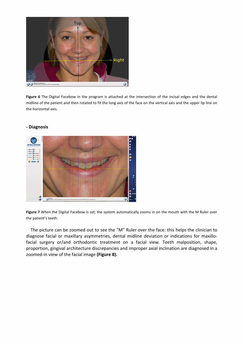
Figure 6 The Digital Facebow in the program is attached at the intersection of the incisal edges and the dental midline of the patient and then rotated to fit the long axis of the face on the vertical axis and the upper lip line on the horizontal axis. - Diagnosis
Figure 7 When the Digital Facebow is set; the system automatically zooms in on the mouth with the M Ruler over the patient’s teeth. The picture can be zoomed out to see the “M” Ruler over the face: this helps the clinician to diagnose facial or maxillary asymmetries, dental midline deviation or indications for maxillo-facial surgery or/and orthodontic treatment on a facial view. Teeth malposition, shape, proportion, gingival architecture discrepancies and improper axial inclination are diagnosed in a zoomed-in view of the facial image (Figure 8).
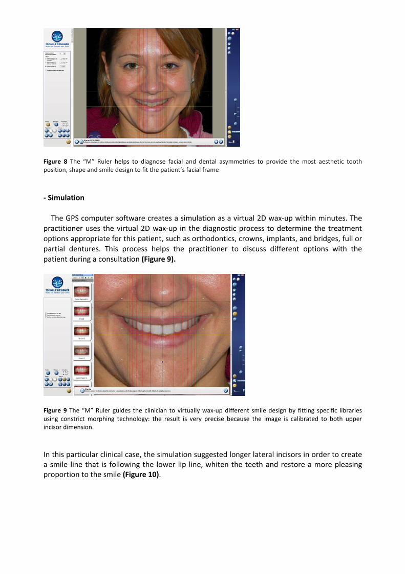
Figure 8 The “M” Ruler helps to diagnose facial and dental asymmetries to provide the most aesthetic tooth position, shape and smile design to fit the patient’s facial frame
- Simulation
The GPS computer software creates a simulation as a virtual 2D wax-up within minutes. The practitioner uses the virtual 2D wax-up in the diagnostic process to determine the treatment options appropriate for this patient, such as orthodontics, crowns, implants, and bridges, full or partial dentures. This process helps the practitioner to discuss different options with the patient during a consultation (Figure 9).
Figure 9 The “M” Ruler guides the clinician to virtually wax-up different smile design by fitting specific libraries using constrict morphing technology: the result is very precise because the image is calibrated to both upper incisor dimension.
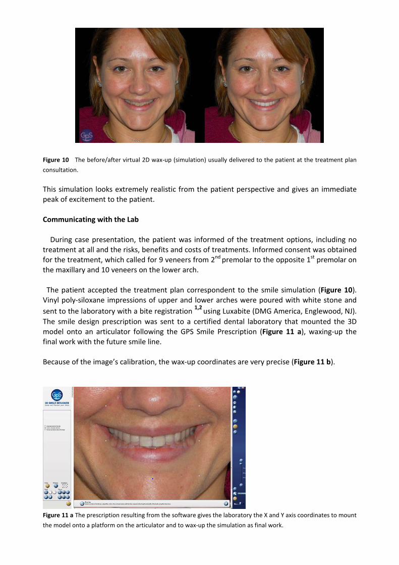
In this particular clinical case, the simulation suggested longer lateral incisors in order to create a smile line that is following the lower lip line, whiten the teeth and restore a more pleasing proportion to the smile (Figure 10).
Figure 10 The before/after virtual 2D wax-up (simulation) usually delivered to the patient at the treatment plan consultation. This simulation looks extremely realistic from the patient perspective and gives an immediate peak of excitement to the patient. Communicating with the Lab During case presentation, the patient was informed of the treatment options, including no treatment at all and the risks, benefits and costs of treatments. Informed consent was obtained for the treatment, which called for 9 veneers from 2nd premolar to the opposite 1st premolar on the maxillary and 10 veneers on the lower arch. The patient accepted the treatment plan correspondent to the smile simulation (Figure 10). Vinyl poly-siloxane impressions of upper and lower arches were poured with white stone and sent to the laboratory with a bite registration 1,2 using Luxabite (DMG America, Englewood, NJ). The smile design prescription was sent to a certified dental laboratory that mounted the 3D model onto an articulator following the GPS Smile Prescription (Figure 11 a), waxing-up the final work with the future smile line. Because of the image’s calibration, the wax-up coordinates are very precise (Figure 11 b).
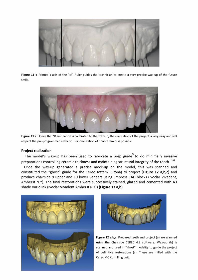
Figure 11 a The prescription resulting from the software gives the laboratory the X and Y axis coordinates to mount the model onto a platform on the articulator and to wax-up the simulation as final work.
Figure 11 b Printed Y-axis of the “M” Ruler guides the technician to create a very precise wax-up of the future smile.
Figure 11 c Once the 2D simulation is calibrated to the wax-up, the realization of the project is very easy and will respect the pre-programmed esthetic. Personalization of final ceramics is possible. Project realization The model’s wax-up has been used to fabricate a prep guide3 to do minimally invasive preparations controlling ceramic thickness and maintaining structural integrity of the tooth. 3,4
Once the wax-up generated a precise mock-up on the model, this was scanned and constituted the “ghost” guide for the Cerec system (Sirona) to project (Figure 12 a,b,c) and produce chairside 9 upper and 10 lower veneers using Empress CAD blocks (Ivoclar Vivadent, Amherst N.Y). The final restorations were successively stained, glazed and cemented with A3 shade Variolink (Ivoclar Vivadent Amherst N.Y.) (Figure 13 a,b)
Figure 12 a,b,c Prepared teeth and project (a) are scanned using the Chairside CEREC 4.2 software. Wax-up (b) is scanned and used in “ghost” modality to guide the project of definitive restorations (c). These are milled with the Cerec MC XL milling unit.
Figure 13 a,b The final restorations were realized with a CAD/CAM technique using the Ivoclar Empress CAD blocks milled with the Sirona CEREC system In an optimal smile arch, the curvature of the maxillary incisal edges should coincide with or be parallel to the border of the lower lip in smiling.5 In this case, the smile line has been improved to follow the lower lip line contour, and the final smile results are in harmony with the patient's face. Upper centrals are dominant and teeth were designed to the specific width and length and shape with the GPS program in order to correctly “fit” the patient’s face. The final esthetic outcome is the reflection of the virtual 2D wax-up accepted by the patient (Figure 10) and respects the patient’s expectations resulting in better smile and improved facial look (Figure 14 a, b). Figure 14 a,b Final smile and improvement of facial aspect. The smile design contributes to change the appearance of the patient. References
1. Morley J. The Role of Cosmetic Dentistry in Restoring a Youthful Appearance JADA 2009 2. Margeas, R. A simple technique guide for a complex veneer case Oral Health 2000:75-89 3. Magne P, Belser U. Bonded Porcelain Restorations in the Anterior Dentition: A Biomimetic Approach.
Quintessence Pub. 2002. 4. Goodlin, R.M. Minimally invasive Dentistry Cdn J Cos Dent Vol 4 No1 April 2008:43-45 5. Sabri R. OVERVIEW The Eight Components of a Balanced Smile. Journal of Clinical orthodontics 2005 ;