NATURAL SOUND DIGITAL SOUND FIELD PROCESSOR/AMPLIFIER DSP-E580 D D S S P P - - E E 5 5 8 8 0 0 CONTENTS PRECAUTIONS & SAFETY INSTRUCTIONS ....................Inside Front Cover SETUP & ADJUSTMENT..................................................................................3 1-1. GETTING STARTED.................................................................................3 1-2. SETUP .......................................................................................................8 1-3. CONTROLS & ADJUSTMENTS.............................................................18 1-4. ADJUSTMENT.........................................................................................21 GENERAL OPERATION .................................................................................24 2-1. PLAYING A SOURCE .............................................................................24 2-2. DIGITAL SOUND FIELD PROGRAMS ..................................................25 2-3. SELECTING SOUND FIELD PROGRAMS............................................25 2-4. MUTING THE EFFECT SOUND ............................................................25 2-5. SUPERIMPOSED VIDEO PROGRAM/PARAMETER DISPLAY ..................................................................................................25 2-6. DESCRIPTIONS OF THE SOUND FIELD PROGRAMS ......................26 CREATING YOUR OWN SOUND FIELDS ....................................................30 3-1. SELECTING AND EDITING PROGRAM PARAMETERS ....................30 3-2. DESCRIPTIONS OF THE DIGITAL SOUND FIELD PARAMETERS ........................................................................................32 TROUBLESHOOTING ....................................................................................34 SPECIFICATIONS ...........................................................................................35 OPERATION MANUAL DIGITAL SOUND FIELD PROCESSING AMPLIFIER
Transcript
DSP
PRO LOGIC
TAPEMONITOR
PROGRAM
EFFECT
NATURAL SOUND DIGITAL SOUND FIELD PROCESSOR/AMPLIFIER DSP-E580
DDSSPP--EE558800
CONTENTS
PRECAUTIONS & SAFETY INSTRUCTIONS ....................Inside Front Cover
GENERAL OPERATION.................................................................................242-1. PLAYING A SOURCE.............................................................................242-2. DIGITAL SOUND FIELD PROGRAMS ..................................................252-3. SELECTING SOUND FIELD PROGRAMS............................................25
2-4. MUTING THE EFFECT SOUND ............................................................252-5. SUPERIMPOSED VIDEO PROGRAM/PARAMETER
DISPLAY..................................................................................................252-6. DESCRIPTIONS OF THE SOUND FIELD PROGRAMS ......................26
CREATING YOUR OWN SOUND FIELDS ....................................................303-1. SELECTING AND EDITING PROGRAM PARAMETERS ....................303-2. DESCRIPTIONS OF THE DIGITAL SOUND FIELD
1 Read Instructions – All the safetyand operating instructions should be readbefore the unit is operated.
2 Retain Instructions – The safety andoperating instructions should be retainedfor future reference.
3 Heed Warnings – All warnings on theunit and in the operating instructionsshould be adhered to.
4 Follow Instructions – All operatingand other instructions should be followed.
5 Water and Moisture – The unitshould not be used near water – forexample, near a bathtub, washbowl,kitchen sink, laundry tub, in a wetbasement, or near a swimming pool, etc.
6 Carts and Stands – The unit shouldbe used only with a cart or stand that isrecommended by the manufacturer.
6A A unit and cart combination shouldbe moved with care. Quickstops, excessive force, anduneven surfaces maycause the unit and cartcombination to overturn.
7 Wall or Ceiling Mounting – The unitshould be mounted to a wall or ceilingonly as recommended by themanufacturer.
8 Ventilation – The unit should besituated so that its location or positiondoes not interfere with its properventilation. For example, the unit shouldnot be situated on a bed, sofa, rug, orsimilar surface, that may block theventilation openings; or placed in a built-in installation, such as a bookcase orcabinet that may impede the flow of airthrough the ventilation openings.
9 Heat – The unit should be situatedaway from heat sources such asradiators, stoves, or other appliances thatproduce heat.
10 Power Sources – The unit should beconnected to a power supply only of thetype described in the operatinginstructions or as marked on the unit.
11 Power-Cord Protection – Power-supply cords should be routed so thatthey are not likely to be walked on orpinched by items placed upon or againstthem, paying particular attention to cordsat plugs, convenience receptacles, andthe point where they exit from the unit.
12 Cleaning – The unit should becleaned only as recommended by themanufacturer.
13 Nonuse Periods – The power cord ofthe unit should be unplugged from theoutlet when left unused for a long periodof time.
14 Object and Liquid Entry – Careshould be taken so that objects do not fallinto and liquids are not spilled into theinside of the unit.
15 Damage Requiring Service – Theunit should be serviced by qualifiedservice personnel when:A. The power-supply cord or the plughas been damaged;orB. Objects have fallen, or liquid hasbeen spilled into the unit; orC. The unit has been exposed to rain;orD. The unit does not appear to operatenormally or exhibits a marked change inperformance; orE. The unit has been dropped, or thecabinet damaged.
16 Servicing – The user should notattempt to service the unit beyond thosemeans described in the operatinginstructions. All other servicing should bereferred to qualified service personnel.
17 Power Lines – An outdoor antennashould be located away from power lines.
18 Grounding or Polarization –Precautions should be taken so that thegrounding or polarization is not defeated.
SAFETY INSTRUCTIONS
RISK OF ELECTRIC SHOCKDO NOT OPEN
CAUTION: TO REDUCE THE RISK OFELECTRIC SHOCK, DO NOT REMOVE
COVER (OR BACK), NO USER-SERVICEABLEPARTS INSIDE, REFER SERVICING TO
QUALIFIED SERVICE PERSONNEL.
The lightning flash with arrowheadsymbol, within an equilateral triangle,is intended to alert you to thepresence of uninsulated “dangerousvoltage” within the product’senclosure that may be of sufficientmagnitude to constitute a risk ofelectric shock to persons.
The exclamation point within anequilateral triangle is intended to alertyou to the presence of importantoperating and maintenance(servicing) instructions in theliterature accompanying theappliance.
• Explanation of Graphical Symbols
CAUTION
IMPORTANT!Please record the serial number of thisunit in the space below.
Model:Serial No.:
The serial number is located on the rearof the unit.Retain this Owner’s Manual in a safeplace for future reference.
WARNINGTO REDUCE THE RISK OF FIRE ORELECTRIC SHOCK, DO NOT EXPOSETHIS UNIT TO RAIN OR MOISTURE.
PRECAUTIONS & SAFETY INSTRUCTIONS
1
1 To ensure the finest performance,please read this manual carefully. Keep it ina safe place for future reference.
2 Install your unit in a cool, dry, cleanplace – away from windows, heat sources,and too much vibration, dust, moisture orcold. Avoid sources of hum (transformers,motors). To prevent fire or electrical shock,do not expose to rain and water.
3 Do not operate the unit upside-down. Itmay overheat, possibly causing damage.
4 Never open the cabinet. If a foreignobject drops into the set, contact yourdealer.
5 Do not use force on switches, knobs orcords. When moving the set, first turn theunit off. Then gently disconnect the powerplug and the cords connecting to otherequipment. Never pull the cord itself.
6 Do not attempt to clean the unit withchemical solvents; this might damage thefinish. Use a clean, dry cloth.
7 Always set the volume control to “–∞”while lowering the tonearm to play a record;turn the volume up with the stylus in thegroove.
8 Be sure to read the “Troubleshooting”section on common operating errors before concluding that your unit is faulty.
9 Do not connect audio equipment to theAC outlets on the rear panel if thatequipment requires more power than theoutlets are rated to provide.
We Want You ListeningFor A LifetimeYAMAHA and the Electronic IndustriesAssociation’s Consumer ElectronicsGroup want you to get the most out ofyour equipment by playing it at a safelevel. One that lets the sound comethrough loud and clear without annoyingblaring or distortion – and, mostimportantly, without affecting yoursensitive hearing. Since hearing damagefrom loud sounds is often undetectableuntil it is too late, YAMAHA and theElectronic IndustriesAssociation’s ConsumerElectronics Grouprecommend you to avoidprolonged exposure fromexcessive volume levels.
PRECAUTIONSFCC INFORMATION
1. IMPORTANT NOTICE : DO NOT MODIFY THIS UNIT!This product, when installed as indicated in the instructions contained in thismanual, meets FCC requirements. Modifications not expressly approved byYamaha may void your authority, granted by the FCC, to use the product.
2. IMPORTANT : When connecting this product to accessories and/or anotherproduct use only high quality shielded cables. Cable/s supplied with this productMUST be used. Follow all installation instructions. Failure to follow instructionscould void your FCC authorization to use this product in the USA.
3. NOTE : This product has been tested and found to comply with the requirementslisted in FCC Regulations, Part 15 for Class “B” digital devices. Compliance withthese requirements provides a reasonable level of assurance that your use ofthis product in a residential environment will not result in harmful interferencewith other electronic devices.This equipment generates/uses radio frequencies and, if not installed and usedaccording to the instructions found in the users manual, may cause interferenceharmful to the operation of other electronic devices.Compliance with FCC regulations does not guarantee that interference will notoccur in all installations. If this product is found to be the source of interference,which can be determined by turning the unit “OFF” and “ON”, please try toeliminate the problem by using one of the following measures:
Relocate either this product or the device that is being affected by theinterference.
Utilize power outlets that are on different branch (circuit breaker or fuse) circuitsor install AC line filter/s.
In the case of radio or TV interference, relocate/reorient the antenna. If theantenna lead-in is 300 ohm ribbon lead, change the lead-in to coaxial typecable.
If these corrective measures do not produce satisfactory results, please contactthe local retailer authorized to distribute this type of product. If you can notlocate the appropriate retailer, please contact Yamaha Electronics Corp., U.S.A.6660 Orangethorpe Ave, Buena Park, CA 90620.
The above statements apply ONLY to those products distributed by YamahaCorporation of America or its subsidiaries.
2
Congratulations!You are the proud owner of a Yamaha Digital Sound Field Processing (DSP) System—an
extremely sophisticated audio component. The DSP system takes full advantage of Yamaha’sundisputed leadership in the field of digital audio processing to bring you a whole new worldof listening experiences. Follow the instructions in this manual carefully when setting up yoursystem, and the DSP system will sonically transform your room into a wide range of listeningenvironments—anything from a famous concert hall to a cozy jazz club. In addition, you getincredible realism from Dolby-Surround encoded video sources using the built-in Dolby ProLogic Surround Decoder.
Rather than tell you about the wonders of digital sound field processing, however, let’s getright down to the business of setting up the system and trying out its many capabilities.Please read this operation manual carefully and store it in a safe place for later reference.
1-1. GETTING STARTED
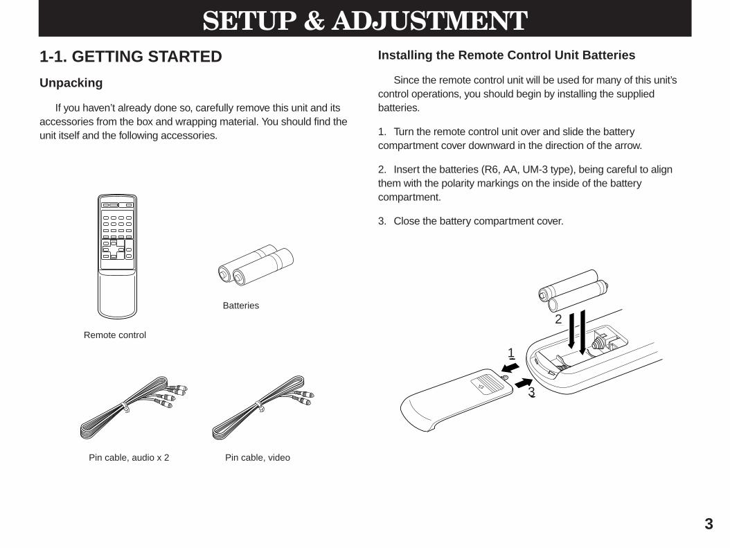
Unpacking
If you haven’t already done so, carefully remove this unit and itsaccessories from the box and wrapping material. You should find theunit itself and the following accessories.
Installing the Remote Control Unit Batteries
Since the remote control unit will be used for many of this unit’scontrol operations, you should begin by installing the suppliedbatteries.
1. Turn the remote control unit over and slide the batterycompartment cover downward in the direction of the arrow.
2. Insert the batteries (R6, AA, UM-3 type), being careful to alignthem with the polarity markings on the inside of the batterycompartment.
3. Close the battery compartment cover.
3
SETUP & ADJUSTMENT
Remote control
Batteries
2
3
1
Pin cable, audio x 2 Pin cable, video
1
2
3
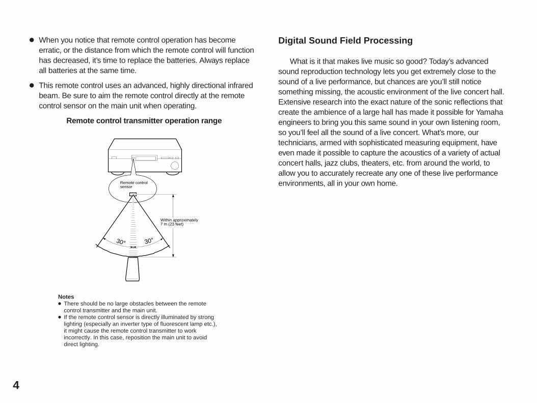
When you notice that remote control operation has becomeerratic, or the distance from which the remote control will functionhas decreased, it’s time to replace the batteries. Always replaceall batteries at the same time.
This remote control uses an advanced, highly directional infraredbeam. Be sure to aim the remote control directly at the remotecontrol sensor on the main unit when operating.
Remote control transmitter operation range
Notes There should be no large obstacles between the remote
control transmitter and the main unit. If the remote control sensor is directly illuminated by strong
lighting (especially an inverter type of fluorescent lamp etc.),it might cause the remote control transmitter to workincorrectly. In this case, reposition the main unit to avoiddirect lighting.
Digital Sound Field Processing
What is it that makes live music so good? Today’s advancedsound reproduction technology lets you get extremely close to thesound of a live performance, but chances are you’ll still noticesomething missing, the acoustic environment of the live concert hall.Extensive research into the exact nature of the sonic reflections thatcreate the ambience of a large hall has made it possible for Yamahaengineers to bring you this same sound in your own listening room,so you’ll feel all the sound of a live concert. What’s more, ourtechnicians, armed with sophisticated measuring equipment, haveeven made it possible to capture the acoustics of a variety of actualconcert halls, jazz clubs, theaters, etc. from around the world, toallow you to accurately recreate any one of these live performanceenvironments, all in your own home.
4
30° 30°
Remote controlsensor
Within approximately7 m (23 feet)
Dolby Pro Logic Surround
The Dolby Pro Logic Surround Decoder program lets youexperience the dramatic realism and impact of Dolby Surround movietheater sound in your own home. Dolby Pro Logic gets its name fromits professional-grade steering logic circuitry, which provides greatereffective channel separation for a much higher degree of realism thanthe “passive” Dolby Surround circuits found in today’s typical homeaudio/video equipment. Dolby Pro Logic Surround provides a truecenter channel, so that there are four independent channels, unlikepassive Dolby Surround, which has in effect only three channels: left,right, and rear. This center channel allows listeners seated in evenless-than-ideal positions to hear the dialog originating from the actionon the screen while experiencing good stereo imaging.
This Dolby Pro Logic Surround Decoder employs a digital signalprocessing system. This system improves the stability of sound ateach channel and crosstalk between channels, so that positioning ofsounds around the room is more accurate compared withconventional analog signal processing systems.
In addition, this unit features a built-in automatic input balancecontrol. This always assures you the best performance withoutmanual adjustment.
Manufactured under license from Dolby Laboratories LicensingCorporation. Additionally licensed under one or more of the followingpatents: U.S. number 3,959,590; Canadian numbers 1,004,603 and1,037,877. “Dolby”, “Pro Logic”, and the double-D symbol aretrademarks of Dolby Laboratories Licensing Corporation.
Dolby Pro Logic Surround + DSP
Additionally you can enjoy sound environment created by thecombination of Dolby Pro Logic and YAMAHA DSP. Precise soundmovement and orientation by the Dolby Pro Logic technology isadded to sound fields which are precisely recreated on thebasis of actual acoustic environments by the DSP technology,so it is suitable for any Audio/Video source with video image.This combination is used on sound field programs No.5 throughNo.14, and No.16.
The YAMAHA “CINEMA DSP” logo indicates these programscreated by the combination of Dolby Pro Logic and YAMAHA DSPtechnology.
5
Setting Up Your Speaker System
This unit has been designed to provide the best sound fieldquality with a full five-speaker system setup, using one extra pairs ofeffect speakers to generate the sound field plus one center speakerfor dialog, when using Dolby Pro Logic Surround decoding. Wetherefore recommend that you use a five-speaker setup. A four-speaker system using only one pair of effect speakers for the soundfield will still provide impressive ambience and effects, however, andmay be a good way to begin with this unit. You can always upgradeto the full five speaker system later.
Use of the Center Dialog Speaker Is Recommended
With digital sound field programs No. 5 through No. 16, by usingeither the Directional Enhancement circuit or the Dolby Pro Logicdecoder, decoded signals will be output from the center channel.Therefore, if you want to upgrade the Audio/Video home theatersystem, it is recommended to use the center speaker unit.
If for some reason it is not practical to use a center speaker, it ispossible to enjoy movie viewing without it. Best results, however, areobtained with the full system.
It is also possible to further expand your system with the additionof a subwoofer and amplifier. You may wish to choose theconvenience of a Yamaha Active Servo Processing SubwooferSystem, which has its own built-in power amp.
6
5 Speaker System
This is the recommended speakersystem, providing the best soundeffects.
With sound field programs No. 1through No. 4, using effect speakersreproduces the effective sound field.With the sound field programs No. 5through No. 16, the center speakerprovides precise center localization.
Center Mode—Set to NRML or WD.(See page 23.)
4 Speaker System
Simple system without centerspeaker.
With sound field programs No. 1through No. 4, a sound effect matchingthat of a 5-speaker system can beobtained. With sound field programs No.5 through No. 16, center sound is outputfrom the left and right main speakers.
Center Mode—Set to PHNTM.(See page 23.)
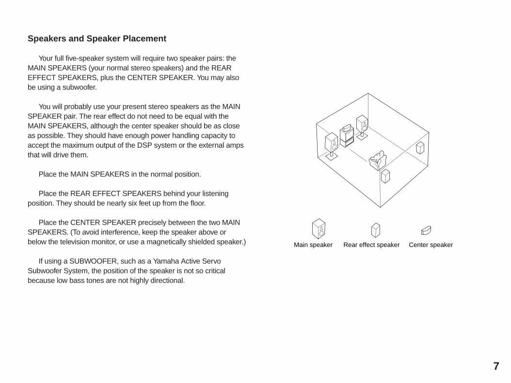
Speakers and Speaker Placement
Your full five-speaker system will require two speaker pairs: theMAIN SPEAKERS (your normal stereo speakers) and the REAREFFECT SPEAKERS, plus the CENTER SPEAKER. You may alsobe using a subwoofer.
You will probably use your present stereo speakers as the MAINSPEAKER pair. The rear effect do not need to be equal with theMAIN SPEAKERS, although the center speaker should be as closeas possible. They should have enough power handling capacity toaccept the maximum output of the DSP system or the external ampsthat will drive them.
Place the MAIN SPEAKERS in the normal position.
Place the REAR EFFECT SPEAKERS behind your listeningposition. They should be nearly six feet up from the floor.
Place the CENTER SPEAKER precisely between the two MAINSPEAKERS. (To avoid interference, keep the speaker above orbelow the television monitor, or use a magnetically shielded speaker.)
If using a SUBWOOFER, such as a Yamaha Active ServoSubwoofer System, the position of the speaker is not so criticalbecause low bass tones are not highly directional.
7
Main speaker Rear effect speaker Center speaker
8
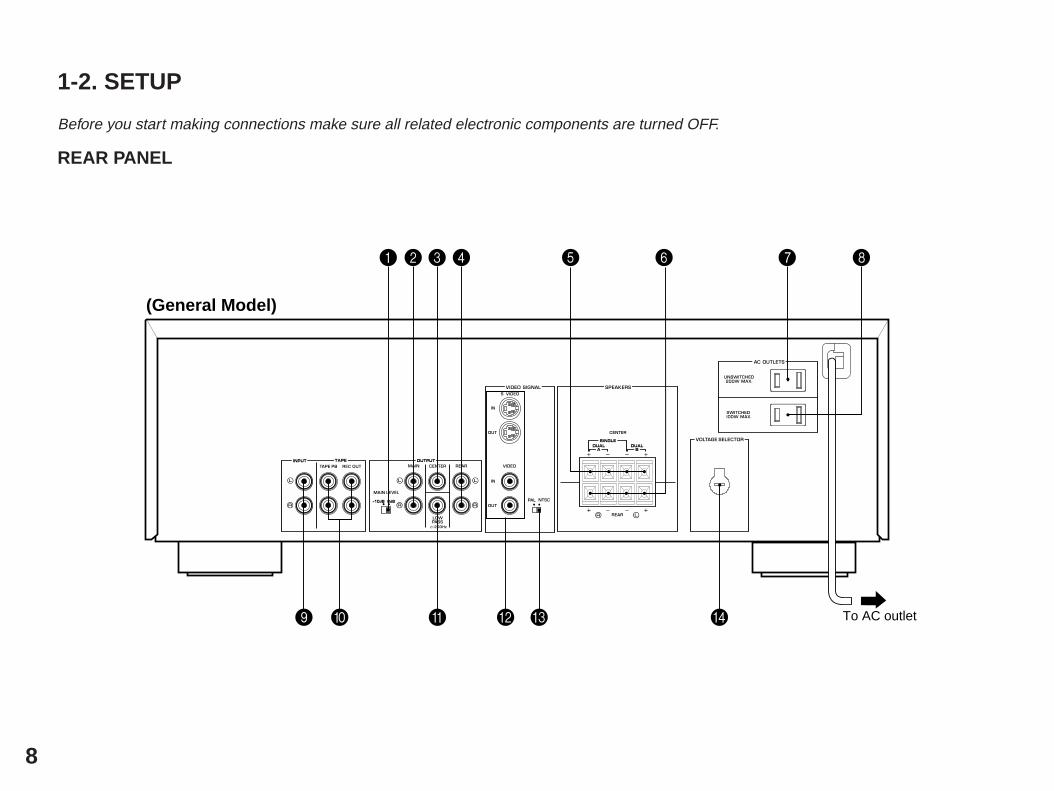
1-2. SETUP
Before you start making connections make sure all related electronic components are turned OFF.
REAR PANEL
SINGLE
DUALDUAL
INPUT TAPE OUTPUT
SINGLE
A B
10dB 0dB-
To AC outlet
1 5 7
9 D
23 4 6 8
0 A CB
(General Model)
1 Main Level SwitchNormally set to “0 dB”. If desired, you can decrease the main-channel line output level at the MAIN OUTPUT jacks by 10 dB bysetting this switch to “–10 dB”.
2Main Output JacksMain-channel line output. Connected to input jacks of externalstereo power amplifier (MAIN IN or AUX or TAPE PLAY jacks ofintegrated amplifier or receiver).
3 Center Output JackCenter-channel line output. Can be connected to input jack of anexternal power amplifier driving the center speaker.
4 Rear Effect Output JacksRear-channel line output. Can be connected to input jacks of anexternal stereo power amplifier driving the rear effect speakers.
5 Center Speaker TerminalsWhen using the built-in center-channel amplifier, connect thecenter speaker(s) here.
6 Rear Effect Speaker TerminalsWhen using the built-in rear-channel amplifier, connect the reareffect speakers here.
7 Unswitched AC OutletYou may plug another component into this socket as long as itspower consumption does not exceed the specified valueshown. “Unswitched” means that power is available even whenthis unit is off.
8 Switched AC Outlet (U.S.A., Canada and General Model)The power consumption of a component plugged into thissocket should not exceed the specified value shown.“Switched” means that component is turned on and off by thisunit’s power switch.
9 Input JacksAccept input from a preamplifier, the “PRE OUT” or “TAPE REC”outputs from an integrated amplifier, or direct input from a line-level source.
0 Tape Rec Out and Playback JacksConnect the inputs and outputs of a stereo tape deck forconvenient recording and playback via this unit (the effect soundcannot be recorded).
A Low Pass JackWhen using a subwoofer, connect its amplifier input to this jack.Frequencies below 200 Hz from the left main, right main andcenter channels are output to this jack.
B Video Superimpose Input/Output JacksUsed to display this unit’s current operating status on your videomonitor, superimposed on the picture. Connect the VIDEO OUTjack to the VIDEO IN jack of your monitor. Connect yourintegrated amplifier or control amplifier equipped with video signaloutput jacks or video signal source to the VIDEO IN jack.Alternatively, the S VIDEO OUT and S VIDEO IN jacks can beused for higher resolution and improved picture quality if yourmonitor and video signal source are equipped with S connectors.
9
C Video NTSC/PAL Switch (General Model only)Set this switch to the position corresponding to the standardthat your video equipment employs.
D Voltage Selector (General Model only)Be sure to set to the line voltage in your area before applyingpower. Consult your dealer if unsure of the correct setting.
NOTE: Even if an external power amplifier is connected to the REARor CENTER line output jacks, the corresponding internal amplifier willnot be turned off and output will be available at the speakerterminals.
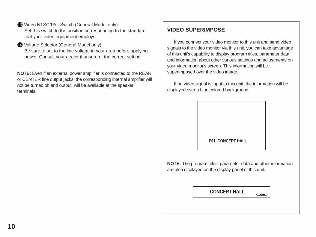
VIDEO SUPERIMPOSE
If you connect your video monitor to this unit and send videosignals to the video monitor via this unit, you can take advantageof this unit’s capability to display program titles, parameter dataand information about other various settings and adjustments onyour video monitor’s screen. This information will besuperimposed over the video image.
If no video signal is input to this unit, the information will bedisplayed over a blue colored background.
NOTE: The program titles, parameter data and other informationare also displayed on the display panel of this unit.
10
CONCERT HALLDSP
P01 CONCERT HALL
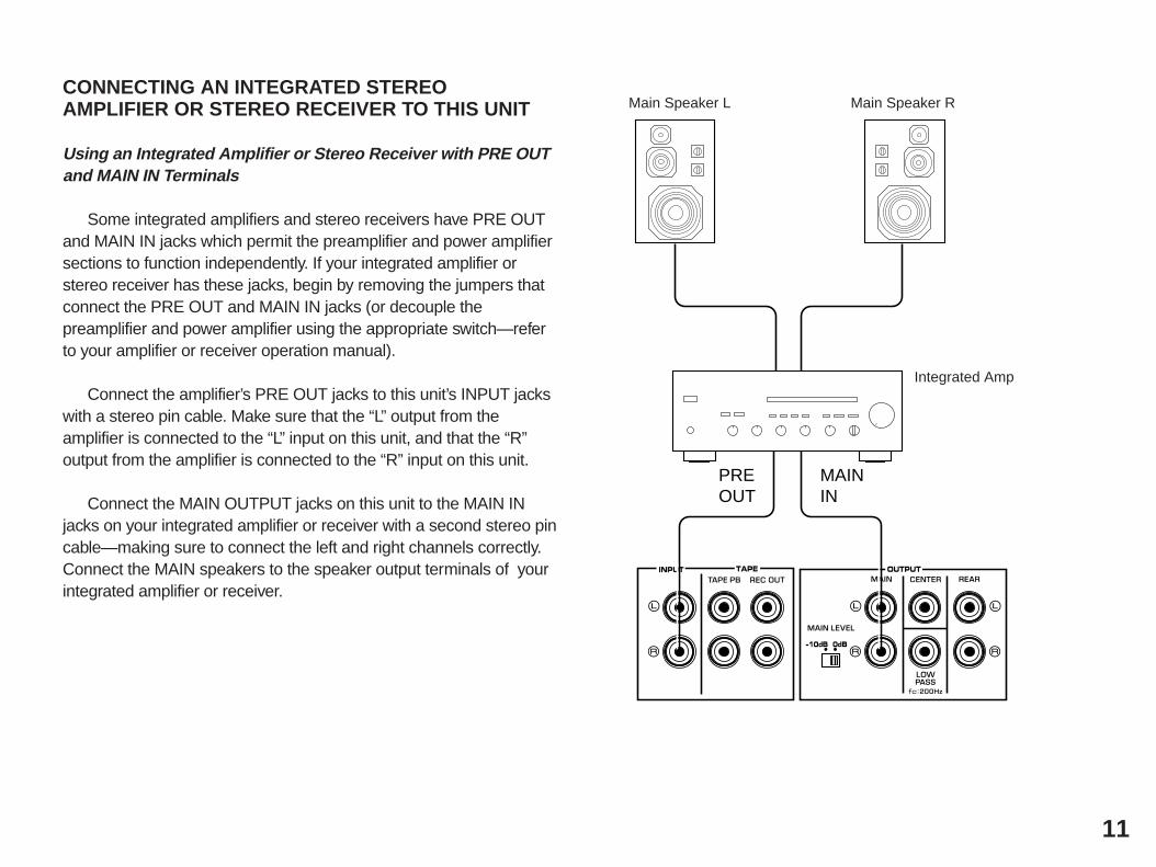
CONNECTING AN INTEGRATED STEREOAMPLIFIER OR STEREO RECEIVER TO THIS UNIT
Using an Integrated Amplifier or Stereo Receiver with PRE OUTand MAIN IN Terminals
Some integrated amplifiers and stereo receivers have PRE OUTand MAIN IN jacks which permit the preamplifier and power amplifiersections to function independently. If your integrated amplifier orstereo receiver has these jacks, begin by removing the jumpers thatconnect the PRE OUT and MAIN IN jacks (or decouple thepreamplifier and power amplifier using the appropriate switch—referto your amplifier or receiver operation manual).
Connect the amplifier’s PRE OUT jacks to this unit’s INPUT jackswith a stereo pin cable. Make sure that the “L” output from theamplifier is connected to the “L” input on this unit, and that the “R”output from the amplifier is connected to the “R” input on this unit.
Connect the MAIN OUTPUT jacks on this unit to the MAIN INjacks on your integrated amplifier or receiver with a second stereo pincable—making sure to connect the left and right channels correctly.Connect the MAIN speakers to the speaker output terminals of yourintegrated amplifier or receiver.
11
INPUT TAPE OUTPUT
10dB 0dB-
MAININ
PREOUT
Main Speaker L Main Speaker R
Integrated Amp
Using an Integrated Amplifier or Stereo Receiver that Does NotHave PRE OUT and MAIN IN Terminals
If your integrated amplifier is NOT equipped with PRE OUT andMAIN IN jacks, this unit must be connected to the amplifier or receiverTAPE jacks. This unit provides additional TAPE PB and REC OUTjacks so you will still have a place to connect your tape deck.
Connect the amplifier or receiver TAPE REC (or TAPE OUT) jacksto this unit’s INPUT jacks with a stereo pin cable. Make sure that the“L” output from the amplifier or receiver is connected to the “L” inputon this unit, and that the “R” output from the amplifier or receiver isconnected to the “R” input on this unit.
Connect the MAIN OUTPUT jacks on this unit to auxiliary (AUX)input jacks, or the TAPE PLAY (or TAPE IN) jacks on your amplifier orreceiver with a second stereo pin cable—making sure to connect theleft and right channels correctly. Connect the MAIN speakers to thespeaker output terminals of the amplifier or receiver.
NOTE: If your system includes a tape deck which has been displacedby connecting this unit to the TAPE jacks, reconnect your tape deck tothis unit’s TAPE PB and REC OUT jacks. REC OUT from this unitgoes to the INPUT jacks on your tape deck, and this unit’s TAPE PBjacks should be connected to the tape deck’s OUTPUT jacks.
12
Main Speaker L Main Speaker R
Integrated Amp
AUX or Tape Play (or Tape In)
INPUT TAPE OUTPUT
10dB 0dB-
INPUTOUTPUT
Tape Rec or Tape Out
Tape Deck
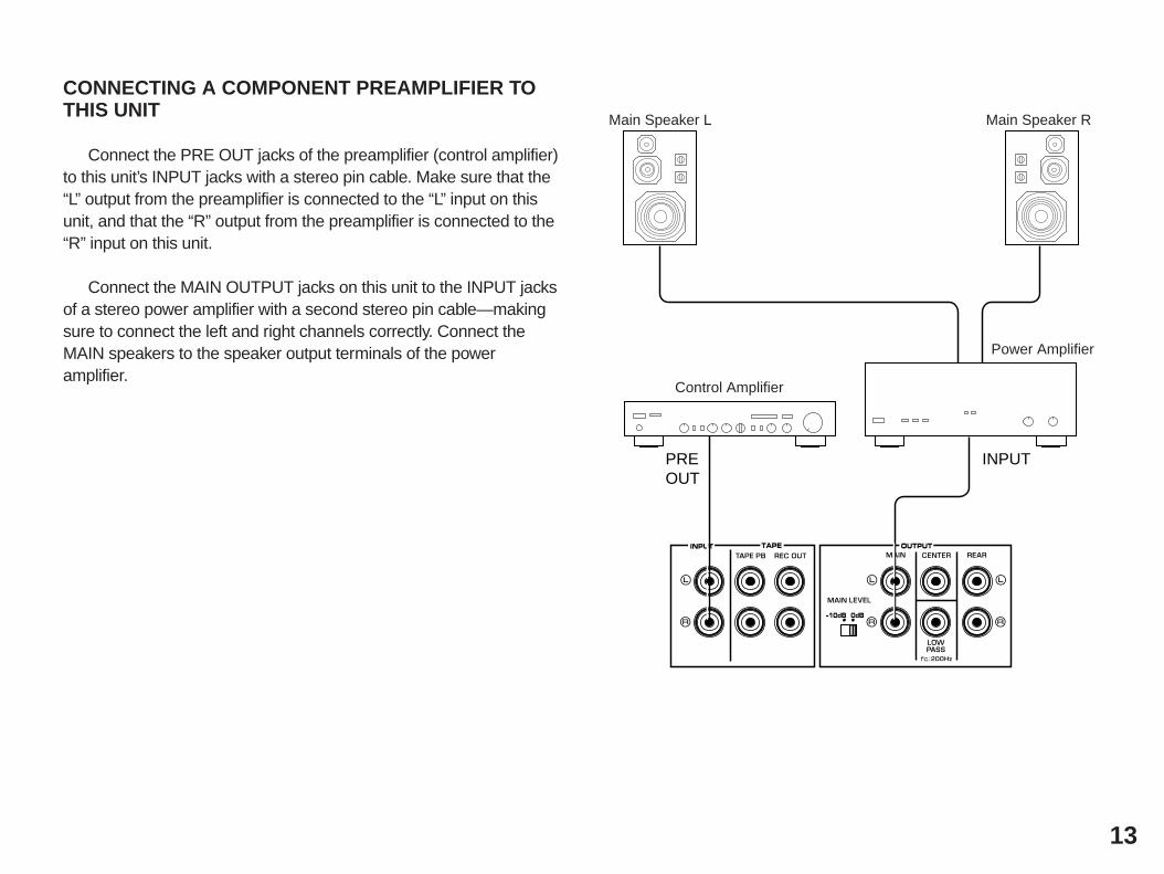
CONNECTING A COMPONENT PREAMPLIFIER TOTHIS UNIT
Connect the PRE OUT jacks of the preamplifier (control amplifier)to this unit’s INPUT jacks with a stereo pin cable. Make sure that the“L” output from the preamplifier is connected to the “L” input on thisunit, and that the “R” output from the preamplifier is connected to the“R” input on this unit.
Connect the MAIN OUTPUT jacks on this unit to the INPUT jacksof a stereo power amplifier with a second stereo pin cable—makingsure to connect the left and right channels correctly. Connect theMAIN speakers to the speaker output terminals of the poweramplifier.
13
Main Speaker L Main Speaker R
Control Amplifier
Power Amplifier
INPUT TAPE OUTPUT
10dB 0dB-
INPUTPREOUT
CONNECTING TO VIDEO SIGNAL JACKS
If your integrated amplifier or similar component is equipped witha video output jack, connect it to this unit’s VIDEO IN jack, andconnect this unit’s VIDEO OUT jack to the video input of yourmonitor.* If your integrated amplifier or similar component is not equipped
with any video output jack, connect the video output jack of yourvideo cassette recorder or another video source to this unit’sVIDEO IN jack directly.
If your integrated amplifier, video cassette recorder, etc. and yourmonitor are equipped with “S” (high-resolution) video terminals,connect the “S” video output from your integrated amplifier or videosource to this unit’s S VIDEO IN jack, and connect this unit’s SVIDEO OUT jack to the “S” video input of your monitor.
NOTE: If video signals are sent to both S VIDEO input and VIDEOinput jacks, the signals will be sent to their respective output jacksindependently.
NOTE: If your unit is the General Model, be sure the NTSC/PALswitch has been correctly set to the standard that your videoequipment employs. U.S.A. and Canada models have no switch anduse the NTSC standard, while other models without a switch use thePAL standard.
Notes about the Video superimpose If you watch a video source which is connected to both S VIDEO
and VIDEO input jacks of this unit, signals of screen displayinformation are output from only the S VIDEO OUT jack.
When no video signal is input to either S VIDEO IN and VIDEO INjacks of this unit, signals of screen display information are outputfrom both S VIDEO OUT and VIDEO OUT jacks with a colorbackground.* For the General Model, if the NTSC/PAL switch on the rear panel
is set to “PAL”, nothing will be output from either S VIDEO OUT orVIDEO OUT jack in this case.
14
Integrated Amplifier etc.
Monitor TV
VIDEOOUT
S VIDEOOUT
VIDEOIN
S VIDEOIN
CONNECTING SPEAKER SYSTEMS
Connect the SPEAKERS terminals to your speakers with wire ofthe proper gauge, cut as short as possible. If the connections arefaulty, no sound will be heard from the speakers. Make sure that thepolarity of the speaker wires is correct, that is, + and – markings areobserved. If these wires are reversed, the sound will be unnaturaland will lack bass. Do not let the bare speaker wires touch eachother or any other metal part as this could damage this unit and/orspeakers.
NOTE: Use speakers with the specified impedance shown on therear of this unit.
Red: positive (+)Black: negative (–)
➀ Press down the tab.➁ Insert the bare wire.
[Remove approx. 5mm (1/4”)insulation from the speakerwires.]
➂ Press up the tab and securethe wire.
CONNECTING THE REAR EFFECT SPEAKERS TOTHIS UNIT
Connect the REAR effect speakers to the REAR SPEAKERSterminals of this unit.
NOTE: If for some reason, you wish to use an external power ampfor the rear effect channel, connect the REAR OUTPUT jacks to theINPUT jacks of the external amp and connect the rear effect speakerpair to the speaker terminals of the external amp.
15
SINGLE
DUALDUALSINGLE
A B
Rear EffectSpeakerR
Rear EffectSpeakerL
➀
➁
➂
16
CONNECTING THE CENTER SPEAKER(S) TO THISUNIT
Connect the CENTER speaker to the CENTER SPEAKERSterminals. One or two CENTER speakers can be connected to thisunit. For the respective connections, follow the methods figuredbelow. If, however, you will not be using a CENTER speaker, be sureto set the Center Mode to “PHNTM” (phantom). (See page 23.)
For connecting one CENTER speaker
For connecting two CENTER speakers
NOTE: If for some reason, you wish to use an external power ampfor the center channel, connect the CENTER OUTPUT jack to theINPUT jack of the external amp and connect the center speaker tothe speaker terminals of the external amp.
SINGLE
DUALDUALSINGLE
A B
SINGLE
DUALDUALSINGLE
A B
Center speaker
Center speaker Center speaker
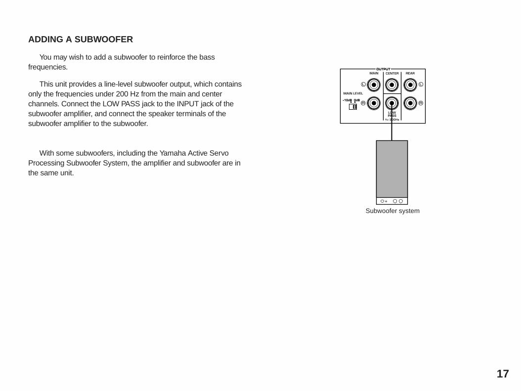
ADDING A SUBWOOFER
You may wish to add a subwoofer to reinforce the bassfrequencies.
This unit provides a line-level subwoofer output, which containsonly the frequencies under 200 Hz from the main and centerchannels. Connect the LOW PASS jack to the INPUT jack of thesubwoofer amplifier, and connect the speaker terminals of thesubwoofer amplifier to the subwoofer.
With some subwoofers, including the Yamaha Active ServoProcessing Subwoofer System, the amplifier and subwoofer are inthe same unit.
17
OUTPUT
10dB 0dB-
Subwoofer system
18
1-3. CONTROLS & ADJUSTMENTS
FRONT PANEL
NATURAL SOUND DIGITAL SOUND FIELD PROCESSOR/AMPLIFIER DSP-E580
TAPEMONITORPROGRAM EFFECT
DSP
PRO LOGIC
1 2 3 4 5 6
9
7 8
(General Model)
1 Power Switch* STANDBY Mode (Europe model only)
While the power is on, pressing the POWER key on the remotecontrol unit switches the unit to the STANDBY mode. (In thismode, the indicator is half illuminated.)
2 Remote control sensorSignals from the remote control unit are received here.
3 Display PanelShows program names, parameters and information about othervarious settings and adjustments.
4 PRO LOGIC IndicatorIlluminates while the built-in Dolby Pro Logic Surround Decoder isbeing activated.
5 DSP IndicatorIlluminates while the built-in Sound Field Processor is beingactivated.
6 Program SelectorSequentially selects the digital sound field processingprograms in the + or – direction.
7 Effect SwitchNormally ON, this switch can be turned OFF to disable outputfrom the center and effect speakers so that the soundbecomes normal 2-channel stereo.
8 Tape Monitor Switch
Used when you have connected the tape deck to this unit’sTAPE terminals to select that tape as the source. (See page 12and 24.)
9 Master Volume ControlSimultaneously controls signal level at all outputs: main, reareffect, center, and subwoofer. (This does not affect TAPE RECOUT level.)
19
REMOTE CONTROL UNIT 1 Power KeyTurns this unit on and off.* (Europe model only): Turns the POWER on mode to the
STANDBY mode and vice versa.
2 Program Select Keys (1 through 16)Select DSP programs 1 through 16.
3 Test SwitchWhen pressed, sends a signal to the main left, center, mainright, and rear effect speakers in turn for easy comparison oflevel settings.
4 Set Menu/Parameter +/– KeysEdit DSP program parameters, make settings/adjustments in theSET MENU mode, or used in the main/center/effect speaker levelbalance adjustment.
5 Effect On/Off KeyCuts off the sound’s output from the rear effect and centerspeakers. To restore the output from those speakers, press thiskey again.
6 Set Menu/Parameter Select KeysSelect DSP program parameters or titles of settings/adjustmentsin the SET MENU mode, or used in the main/center/effectspeaker level balance adjustment.
7 Tape Monitor SwitchUsed when you have connected the tape deck to this unit’sTAPE terminals to select that tape as the source. (See pages12 and 24.)
8 Master Volume +/– KeysIncrease (+) or decrease (–) the master volume level.
20
TEST
EFFECT
SET MENUPARAMETER
MASTERVOLUME
POWER
+—
HALL
CONCERTVIDEO
TVTHEATER
1
CHURCH
OPERA
TVSPORTS
2
JAZZ CLUB
CLASSICFILM
GAME
PRO LOGIC
ROCKCONCERT
ANIMATION
KARAOKE
– ENHANCEDTHEATER70 mm MOVIE
1
5
9
13
2
6
10
14
3
7
11
15
4
8
12
16
+
—
TAPEMON
PROGRAM
1
2
4
6
8
7
3
5
PREPARATION
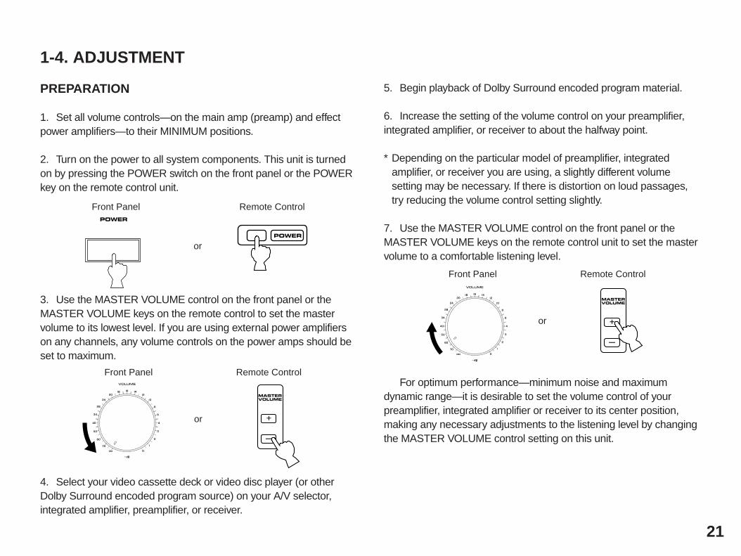
1. Set all volume controls—on the main amp (preamp) and effectpower amplifiers—to their MINIMUM positions.
2. Turn on the power to all system components. This unit is turnedon by pressing the POWER switch on the front panel or the POWERkey on the remote control unit.
3. Use the MASTER VOLUME control on the front panel or theMASTER VOLUME keys on the remote control to set the mastervolume to its lowest level. If you are using external power amplifierson any channels, any volume controls on the power amps should beset to maximum.
4. Select your video cassette deck or video disc player (or otherDolby Surround encoded program source) on your A/V selector,integrated amplifier, preamplifier, or receiver.
5. Begin playback of Dolby Surround encoded program material.
6. Increase the setting of the volume control on your preamplifier,integrated amplifier, or receiver to about the halfway point.
* Depending on the particular model of preamplifier, integratedamplifier, or receiver you are using, a slightly different volumesetting may be necessary. If there is distortion on loud passages,try reducing the volume control setting slightly.
7. Use the MASTER VOLUME control on the front panel or theMASTER VOLUME keys on the remote control unit to set the mastervolume to a comfortable listening level.
For optimum performance—minimum noise and maximumdynamic range—it is desirable to set the volume control of yourpreamplifier, integrated amplifier or receiver to its center position,making any necessary adjustments to the listening level by changingthe MASTER VOLUME control setting on this unit.
This operation uses an internal test-tone generator for balancingthe levels of the main, center and rear effect speakers. All speakersshould be adjusted to the same apparent sound level for properDolby Pro Logic decoding.
1. Depress the TEST switch on the remote control to enter testmode. A hiss-like calibration signal should be heard from the leftmain speaker, center speaker(s), right main speaker and rear effectspeakers in turn (see diagram). Adjust the MASTER VOLUME to anormal listening level.* The state of test-tone output is shown by the display panel and
the monitor screen. (Especially on the monitor screen, it is shownby an image of audio listening room.) This is convenient foradjusting each speaker level.
2. Adjust the center and rear effect speaker level.
For adjusting the center speaker level:Press the SET MENU/PARAMETER select () key. “CENTERLEVEL ··· dB” appears on the display and the test-tone is output fromthe center speaker(s). In this state, adjust the center speaker level bypressing the SET MENU/PARAMETER +/– keys.
For adjusting the rear effect speaker level:Press the SET MENU/PARAMETER Select () key. “SURROUNDLEVEL ··· dB” appears on the display and the test-tone is output fromthe rear effect speakers. In this state, adjust the rear effect speakerlevel by pressing the SET MENU/PARAMETER +/– keys.
Adjust each speaker level so that the sound coming from thecorresponding speakers seems to be at the same level as that fromthe main speakers when you are at a normal listening position. If there is insufficient volume from the effect speakers, you maydecrease the main speaker volume level by setting the MAIN LEVELswitch on the rear panel to “–10 dB”, and adjust the center and rearlevel again.
NOTE: If the CENTER MODE is set to the PHNTM (phantom)position, the center speaker level cannot be adjusted. If using acenter speaker, be sure to set the CENTER MODE to the “NRML” or“WD” position.
After completing this adjustment, press the TEST switch onceagain.
NOTE: Once you have completed these adjustments, use only thisunit’s MASTER VOLUME control to adjust listening volume. Do notchange any other volume settings in the system.
22
Left main Center Right main
Rear
LEFT CENTER RIGHT
SURROUND
OTHER IMPORTANT SETTINGS AND ADJUSTMENTSIN THE “SET MENU” MODE
The following three types of settings and adjustments should bedone before enjoying audio and video sources. Note that thesesettings and adjustments cannot be done without monitoring thedisplay information (or the information displayed on the monitorscreen).
CENTER MODEDIMMERMEMORY GUARD
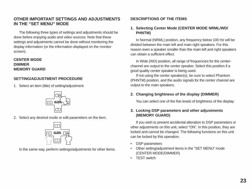
SETTING/ADJUSTMENT PROCEDURE
1. Select an item (title) of setting/adjustment.
2. Select any desired mode or edit parameters on the item.
In the same way, perform settings/adjustments for other items.
DESCRIPTIONS OF THE ITEMS
1. Selecting Center Mode (CENTER MODE NRML/WD/PHNTM)
In Normal (NRML) position, any frequency below 100 Hz will bedivided between the main left and main right speakers. For thisreason even a speaker smaller than the main left and right speakerscan obtain a sufficient effect.
In Wide (WD) position, all range of frequencies for the center-channel are output to the center speaker. Select this position if agood quality center speaker is being used.
If not using the center speaker(s), be sure to select Phantom(PHNTM) position, and the audio signals for the center channel areoutput to the main speakers.
2. Changing brightness of the display (DIMMER)
You can select one of the five levels of brightness of the display.
3. Locking DSP parameters and other adjustments(MEMORY GUARD)
If you wish to prevent accidental alteration to DSP parameters orother adjustments on this unit, select “ON”. In this position, they arelocked and cannot be changed. The following functions on this unitcan be locked by this operation.
• DSP parameters• Other setting/adjustment items in the “SET MENU” mode
(CENTER MODE/DIMMER)• TEST switch
23
SET MENUPARAMETER +—
SET MENUPARAMETER +—
24
2-1. PLAYING A SOURCE
1. Set the MASTER VOLUME control to minimum.
2. Turn the power on.
3. Select a source using the input selector on the integratedamplifier etc.
* To select a tape deck connected to this unit’s TAPE terminals, turnthe TAPE MONITOR switch on so that the indicator over the switchon the front panel lights up. (Otherwise, turn this switch off so thatthe indicator goes off.)
NOTE: If this unit is connected to the TAPE terminals of theintegrated amplifier etc., the following operations are needed.
• If your amplifier has the REC OUT selector which is independentof the input selector;1. Set the input selector to the AUX position.2. Select the source to be input to this unit using the REC OUT
selector.
• If your amplifier does not have the REC OUT selector which isindependent of the input selector;1. Set the TAPE monitor switch on the amplifier to on.2. Select the source to be input to this unit using the input
selector.
4. Play the source.
5. Increase the setting of the MASTER VOLUME control to yourlistening level.
GENERAL OPERATION
POWER
POWER
Front Panel Remote Control
or
MASTERVOLUME
+
—
Front Panel Remote Control
or
Front Panel
TAPEMONITOR
TAPEMON
Front Panel Remote Control
or
2-2. DIGITAL SOUND FIELD PROGRAMS
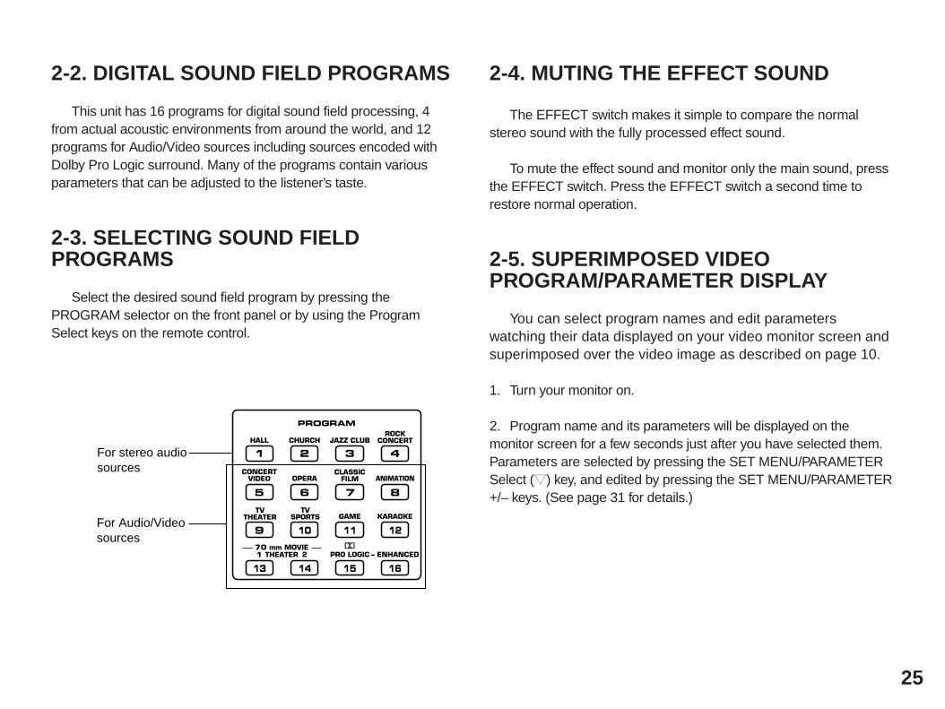
This unit has 16 programs for digital sound field processing, 4from actual acoustic environments from around the world, and 12programs for Audio/Video sources including sources encoded withDolby Pro Logic surround. Many of the programs contain variousparameters that can be adjusted to the listener’s taste.
2-3. SELECTING SOUND FIELDPROGRAMS
Select the desired sound field program by pressing thePROGRAM selector on the front panel or by using the ProgramSelect keys on the remote control.
2-4. MUTING THE EFFECT SOUND
The EFFECT switch makes it simple to compare the normalstereo sound with the fully processed effect sound.
To mute the effect sound and monitor only the main sound, pressthe EFFECT switch. Press the EFFECT switch a second time torestore normal operation.
2-5. SUPERIMPOSED VIDEOPROGRAM/PARAMETER DISPLAY
You can select program names and edit parameterswatching their data displayed on your video monitor screen andsuperimposed over the video image as described on page 10.
1. Turn your monitor on.
2. Program name and its parameters will be displayed on themonitor screen for a few seconds just after you have selected them.Parameters are selected by pressing the SET MENU/PARAMETERSelect () key, and edited by pressing the SET MENU/PARAMETER+/– keys. (See page 31 for details.)
25
HALL
CONCERTVIDEO
TVTHEATER
1
CHURCH
OPERA
TVSPORTS
2
JAZZ CLUB
CLASSICFILM
GAME
PRO LOGIC
ROCKCONCERT
ANIMATION
KARAOKE
– ENHANCEDTHEATER70 mm MOVIE
1
5
9
13
2
6
10
14
3
7
11
15
4
8
12
16
PROGRAM
For stereo audiosources
For Audio/Videosources
26
2-6. DESCRIPTIONS OF THE SOUND FIELD PROGRAMSThe following list gives brief descriptions of the sound fields produced by each of the DSP programs. Keep in mind that most of these are
precise digital recreations of actual acoustic environments. The data for them was recorded at the locations described using sophisticated soundfield measurement equipment.* The channel level balance between the left rear effect speaker and the right rear effect speaker may vary depending on the sound
field you are listening to. This is due to the fact that most of these sound field recreations are actual acoustic environments.
1. CONCERT HALL:
A large round concert hall with a rich surround effect.Pronounced reflections from all directions emphasize theextension of sounds. You will experience the sound field with agreat deal of presence sitting at about the center position nearthe stage.This sound field is also effective for karaoke. This is becauseyou feel as if you are standing on a real stage.
2. CHURCH:
A church in Tokyo shaped like a cross. There is the altar at theupper side of the “cross”, and a pipe organ at the opposite side(the lower side of the cross). It is a very unique shape withwalls all leaning inside, and pillars standing by the side of wallsonly. The sound field has moderate reverberations of whichtime is 2.5 seconds.
3. JAZZ CLUB:
A jazz club in New York. It is in a basement and has a relativelyspacious floor area. The reflection pattern is similar to that of asmall hall.
4. ROCK CONCERT:
The ideal program for lively, dynamic rock music. The data forthis program was recorded at LA’s “hottest” rock club.
5. CONCERT VIDEO:
This program produces an enthusiastic atmosphere and lets youfeel that you are in the midst of the action, as if attending anactual jazz or rock concert.The indirect sound constituent spreads on the surround side ofthe sound field by the use of data of a large round hall for thesurround side, so the image space around the screen and thesound space are fully expanded.
6. OPERA:
This program provides excellent depth of vocals and overallclarity, restraining excessive reverberation.For opera, the orchestra pit and the stage are ideally combined,letting you feel a full presence sound. The rear surround side ofthe sound field is relatively moderated, however, it reproducesbeautiful sound by the use of the data of a concert hall. You willnot be tired from long watching of an opera.
7. CLASSIC FILM:
This program is for reproducing monaural video sources (oldmovies etc.). Monaural sounds are reproduced with muchpresence by the front presence side of the sound field andoptimum reverberation effect. The use of the center speakermakes conversations more audible, obtaining a pleasant mix ofconversations and picture.
8. ANIMATION:
Powerful reverberations on the front presence side of the soundfield adds depth to the image, so expanding the image space. Onthe rear surround side, sounds are reproduced lightly but vividly.The sound field of this program matches image effects ofanimated films regardless of the genre. Conversations, soundsand sound effects are reproduced with vitality by this program. Asource in stereo will obtain more effect, letting you steep yourselfin a fantastic world of animations.
27
9. TV THEATER:
The data of the sound field of a relatively narrow space is used forthe front presence side. A moderately sized spatial sound fieldwithout excessive sound extension and reverberations givesreality to the characters in a drama.The data of the sound field of an opera house is used for the rearsurround side. In a stereo program, background music isreproduced more beautifully with much depth, enhancing soundeffects on the drama. It’s natural sound effect will not make youtired from long watching.
10.TV SPORTS:
Though the front presence side of the sound field is relativelynarrow, the rear surround side employs the sound environment ofa large concert hall. With this program, you can enjoy watchingvarious TV programs such as the news, variety shows, musicprograms or sports programs. In a stereo broadcast of a sportsgame, the commentator is oriented at the center position, and theshouts and the atmosphere in the stadium spreads on thesurround side, however, spreading of them to the rear side isproperly restrained.
11.GAME:
The sound field of a disco is used for the front presence side, andthe sound field of a concert hall in Vienna is used for the rearsurround side.This program reproduces video game music etc. more vividlyemphasizing the fast tempo and lightness of the music. If themusic is in stereo, more effective sound field will be gained by thisprogram.This program is also suitable for karaoke popular music.
12.KARAOKE:
Vocals are reproduced with gentle reverberations on the stagesurrounded by seats in a round hall. A feeling of echo from thehigh ceiling and reverberations in front and behind the hall bringsa lot of presence on both the stage and the seats. By using asource with digital sound, the sound of the greatly instrumentalaccompaniment is much expanded, so emphasizing the spatialeffect with vocals. You feel as if you are standing on a live-stage.
28
29
13.70 mm MOVIE THEATER 1:
This program is ideal for precisely reproducing the sound designof the newest movies. The sound field is made according to thedesign of the newest movie theaters, so the reverberations of thesound field itself are restrained as much as possible. The threedimensional feeling of the sound field is emphasized, and dialogis precisely oriented on the screen. You can enjoy watchingS.F.X., adventure movies, etc. with this program.
14.70 mm MOVIE THEATER 2:
This program is for reproducing sounds on a 70 mm multi-trackfilm, and characterized by a soft and extensive sound field. Thefront presence side of the sound field is relatively narrow. Itspatially spreads all around and toward the screen, restrainingecho effect of conversations without losing clarity. For thesurround side, the data of the sound field of an opera house isused on an enlarged scale, so the harmony of music or chorussounds beautifully in a wide space at the rear of the sound field.
15.PRO LOGIC:
The digital Dolby Pro Logic decoder reproduces sounds andsound effects of a source encoded in Dolby Surround. Therealization of a highly efficient decoding process improvescrosstalk and channel separation and makes sound positioningsmoother and more precise.
16.PRO LOGIC ENHANCED:
This program ideally simulates the multi-surround speakersystems of the 35 mm film theater. Surround signals by the DolbyPro Logic decoder are processed on the surround side of thesound field based on the data of the sound field of a shoe-boxhall. The surround effects produced by this sound field folds theviewer naturally from the rear to the left and right and toward thescreen.
Programs No. 13 through No. 16 reproduces video discs, video tapes and similar sources which are Dolby Surround encoded and bear the“DOLBY SURROUND” logo.
NOTE: The Dolby Pro Logic Surround system is designed to beused with program material (mainly videotaped movie soundtracks)encoded with the Dolby Surround system.
NOTE: If the main and center channel sound is considerablyaltered by overadjustment of the BASS or TREBLE controls, therelationship with the rear channels may produce an unnaturaleffect.
30
3-1. SELECTING AND EDITING PROGRAM PARAMETERSWHAT IS A SOUND FIELD?
In order to explain the impressive functions of the DSP system,we need to first understand what a sound field really is.
What really creates the rich, full tones of a live instrument are themultiple reflections from the walls of the room. In addition to makingthe sound “live”, these reflections enable us to tell where the player issituated, and the size and shape of the room in which we are sitting.We can even tell whether it is highly reflective, with steel and glasssurfaces, or more absorbent—wood panels, carpeting and curtains.
THE ELEMENTS OF A SOUND FIELD
In any environment, in addition to the direct sound comingstraight to our ears from the player’s instrument, there are two distincttypes of sound reflections that combine to make up the sound field:
(1) Early Reflections. Reflected sounds reach our ears extremelyrapidly (50 ms — 100 ms after the direct sound), after reflecting fromone surface only—for example, from the ceiling or a wall. Thesereflections fall into specific patterns as shown in the diagram on page32 for any particular environment, and provide vital information to ourears. Early reflections actually add clarity to the direct sound.
(2) Reverberations. These are caused by reflections from more thanone surface—walls, ceiling, the back of the room—so numerous thatthey merge together to form a continuous sonic “afterglow”. They arenon-directional, and lessen the clarity of the direct sound.
Direct sound, early reflections and subsequent reverberationtaken together help us to determine the subjective size and shape ofthe room, and it is this information that the DSP system reproducesin order to create sound fields.
If you could create the appropriate early reflections andsubsequent reverberations in your listening room, you would be ableto create your own listening environment. The acoustics in your roomcould be changed to those of a concert hall, a dance floor, or virtuallyany size room at all. This ability to create sound fields at will isexactly what Yamaha has done with the DSP system.
DSP programs consist of some parameters to determineapparent room size, reverberation time, distance from you to theperformer, etc. In each program, those parameters are preset withvalues precisely calculated by Yamaha to create the sound fieldunique for the program. It is recommended to use DSP programswithout changing values of parameters, however, this unit also allowsyou to create your own sound fields. Starting with one of the built-inprograms, you can adjust those parameters. Even if power is turnedoff, your custom sound fields will remain in the DSP system’smemory for about two weeks. The following pages detail how tomake your own sound fields.
CREATING YOUR OWN SOUND FIELDS
Each sound field program has a set of parameters that allow youto change the characteristics of the acoustic environment to createprecisely the effect you want. These parameters correspond to themany natural acoustic factors that create the sound field youexperience in an actual concert hall or other listening environment.The size of the room, for example, affects the length of time betweenthe “early reflections”—that is, the first few widely spaced reflectionsyou hear after the direct sound. The “ROOM SIZE” parameterprovided in many of the DSP programs alters the timing betweenthese reflections, thus changing the shape of the “room” you hear. Inaddition to room size, the shape of the room and the characteristicsof its surfaces have a significant effect on the final sound. Surfacesthat absorb sound, for example, cause the reflections andreverberations to die out quicker, while highly reflective surfaces allowthe reflections to carry on for a longer period of time. The DSPparameters allow you to control these and many other factors thatcontribute to your personal sound field, allowing you to essentially“redesign” the concert halls and rooms provided to create custom-tailored listening environments that ideally match your mood andmusic.
Refer to “3-2. DESCRIPTIONS OF THE DIGITAL SOUND FIELDPARAMETERS” on page 32 for a description of what eachparameter does, how it effects the sound, and its control range.
1. With the desired program selected, press the SET MENU/PARAMETER Select () key on the remote control unit once. Thiswill recall the first parameter. In the case of the CONCERT HALLprogram, for example, this would be the INIT. DLY parameter. Youcan continue pressing the SET MENU/PARAMETER Select () keyto select other parameters in sequence. If the key is pressed whenthe last parameter is being displayed, the first parameter is selectedagain.
2. When the desired parameter has been recalled, use the SETMENU/PARAMETER + (increment) and – (decrement) keys tochange its value to create the effect you want. + increases the valueof the selected parameter, and – decreases the value of the selectedparameter. In both cases you can hold the key down for continuousincrementing or decrementing. The display will pause for a momentat the initial value of the parameter as a reminder. (On the monitorscreen, * mark at the head of parameter name disappears at theinitial value of the parameter.)
NOTE: Parameter edits made in this way will remain in effect evenwith power cut due to power failure or the power plug disconnectedfrom the AC outlet for up to about two weeks, after which allparameters, as well as other adjustments or settings on this unit, willreturn to their initial values or conditions.
31
32
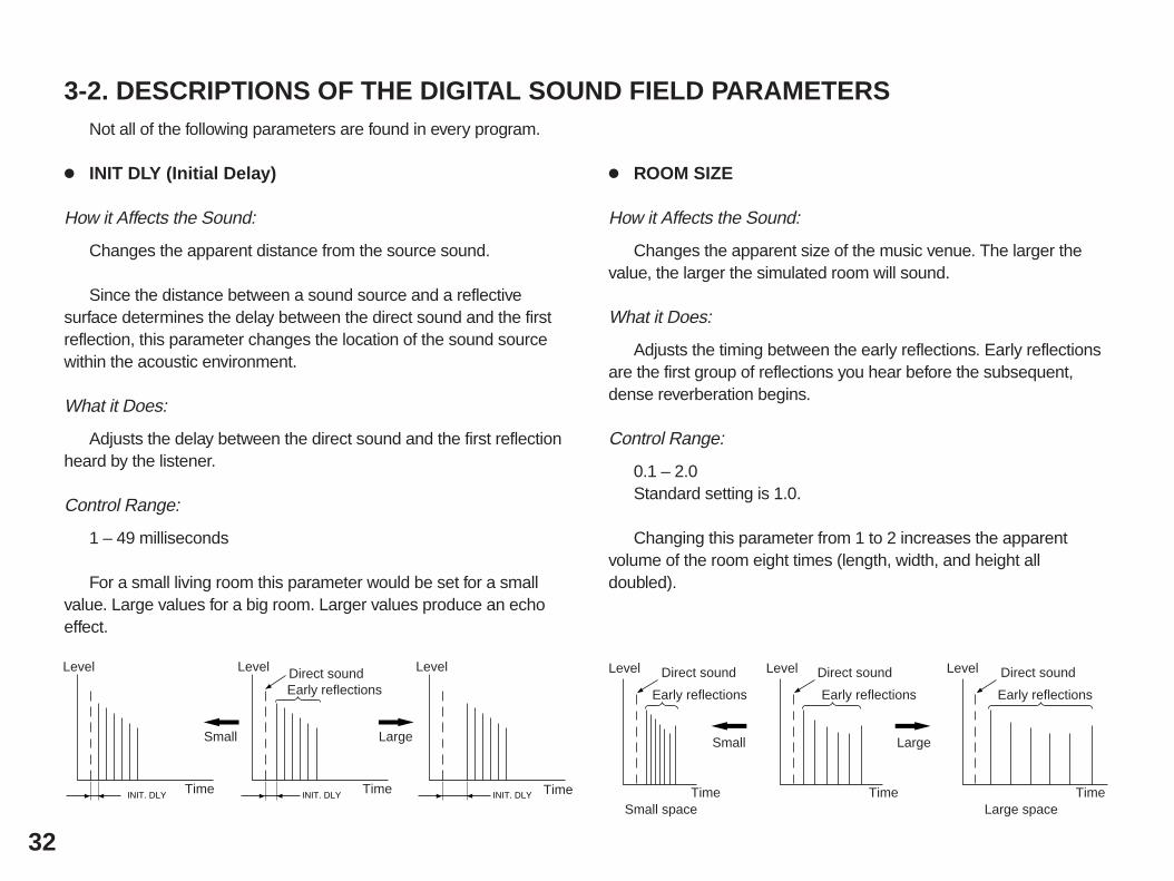
3-2. DESCRIPTIONS OF THE DIGITAL SOUND FIELD PARAMETERSNot all of the following parameters are found in every program.
INIT DLY (Initial Delay)
How it Affects the Sound:
Changes the apparent distance from the source sound.
Since the distance between a sound source and a reflectivesurface determines the delay between the direct sound and the firstreflection, this parameter changes the location of the sound sourcewithin the acoustic environment.
What it Does:
Adjusts the delay between the direct sound and the first reflectionheard by the listener.
Control Range:
1 – 49 milliseconds
For a small living room this parameter would be set for a smallvalue. Large values for a big room. Larger values produce an echoeffect.
ROOM SIZE
How it Affects the Sound:
Changes the apparent size of the music venue. The larger thevalue, the larger the simulated room will sound.
What it Does:
Adjusts the timing between the early reflections. Early reflectionsare the first group of reflections you hear before the subsequent,dense reverberation begins.
Control Range:
0.1 – 2.0Standard setting is 1.0.
Changing this parameter from 1 to 2 increases the apparentvolume of the room eight times (length, width, and height alldoubled).
Level Direct sound
Early reflections
TimeSmall space
Small
Level Direct sound
Early reflections
Time
Large
Level Direct sound
Early reflections
TimeLarge space
INIT. DLY INIT. DLY INIT. DLY
Level
Time
Small
Level Level
Time Time
Large
Direct soundEarly reflections
33
REV. TIME (Reverberation Time)
How it Affects the Sound:
The natural reverberation time of a room depends primarily on itssize and the characteristics of its inner surfaces. This parameter,therefore, changes the apparent size of the acoustic environmentover an extremely wide range.
What it Does:
Adjusts the amount of time it takes for the level of the dense,subsequent reverberation sound to decay by 60 dB (@ 1 kHz).
Control Range:
1.0 – 5.0 seconds.
The reverb time in a small-to-medium size hall would be between1 and 2, and in a large hall it is normally between 2 and 3.
EFCT TRIM (Effect Trim)
Performs fine adjustment of the level of all the effect sounds.
Control Range:
–3 dB to 3 dB
DELAY
Adjusts the delay between the direct sounds (at the main left,center and main right channels) and the effect sounds (at the fronteffect and rear effect channels). The larger the value, the later theeffect sounds are generated.
Control Range:
15 – 30 milliseconds
REV. TIME
60 dB
REV. TIME
60 dB
REV. TIME
60 dB
Level
Reverberations Reverberations Reverberations
Time
Small
Level Level
Time Time
Large
Direct soundEarly reflections
34
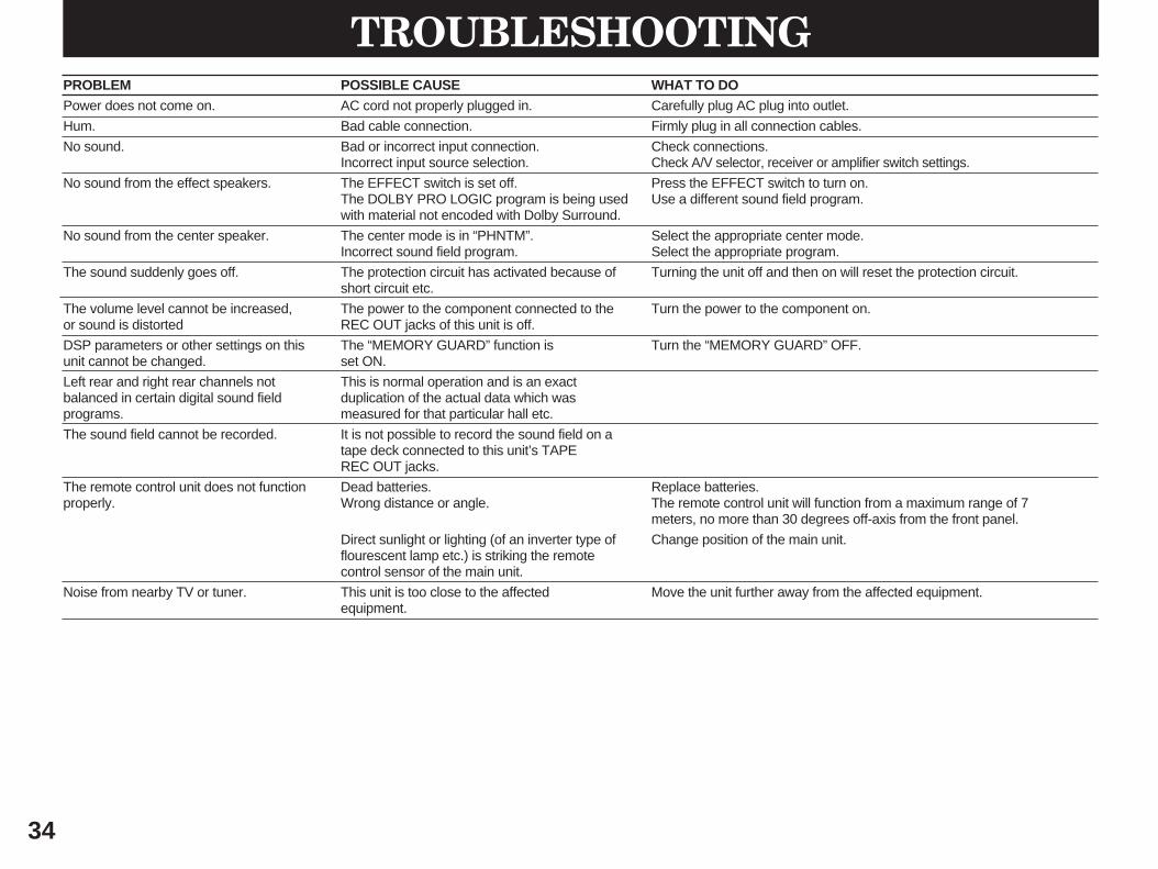
PROBLEM POSSIBLE CAUSE WHAT TO DOPower does not come on. AC cord not properly plugged in. Carefully plug AC plug into outlet.
Hum. Bad cable connection. Firmly plug in all connection cables.
No sound. Bad or incorrect input connection. Check connections.Incorrect input source selection. Check A/V selector, receiver or amplifier switch settings.
No sound from the effect speakers. The EFFECT switch is set off. Press the EFFECT switch to turn on.The DOLBY PRO LOGIC program is being used Use a different sound field program.with material not encoded with Dolby Surround.
No sound from the center speaker. The center mode is in “PHNTM”. Select the appropriate center mode.Incorrect sound field program. Select the appropriate program.
The sound suddenly goes off. The protection circuit has activated because of Turning the unit off and then on will reset the protection circuit.short circuit etc.
The volume level cannot be increased, The power to the component connected to the Turn the power to the component on.or sound is distorted REC OUT jacks of this unit is off.
DSP parameters or other settings on this The “MEMORY GUARD” function is Turn the “MEMORY GUARD” OFF.unit cannot be changed. set ON.
Left rear and right rear channels not This is normal operation and is an exact balanced in certain digital sound field duplication of the actual data which wasprograms. measured for that particular hall etc.
The sound field cannot be recorded. It is not possible to record the sound field on a tape deck connected to this unit’s TAPE REC OUT jacks.
The remote control unit does not function Dead batteries. Replace batteries.properly. Wrong distance or angle. The remote control unit will function from a maximum range of 7
meters, no more than 30 degrees off-axis from the front panel.
Direct sunlight or lighting (of an inverter type of Change position of the main unit.flourescent lamp etc.) is striking the remotecontrol sensor of the main unit.
Noise from nearby TV or tuner. This unit is too close to the affected Move the unit further away from the affected equipment.equipment.
Maximum Voltage Output (20 Hz – 20 kHz 1% THD)PRE OUT (MAIN L/R) ....................................................................................... 3V
Frequency Response (20 Hz – 20 kHz)PRE OUT (MAIN L/R) (EFFECT OFF) ................................................... 0±1.0 dB
Total Harmonic DistortionINPUT to PRE OUT (MAIN L/R)
1V, 20 Hz – 20 kHz (EFFECT OFF)......................................... Less than 0.01%Built-in amplifier (CENTER, REAR L/R)
10W/8Ω, 20 Hz – 20 kHz ......................................................... Less than 0.03%
Signal-to-Noise Ratio (IHF-A Network)INPUT (Input Shorted) (EFFECT OFF) ..................................... More than 98 dB
Residual Noise (IHF-A Network)PRE OUT (MAIN L/R) .................................................................... Less than 5 µV
[U.S.A. and Canada models] ..................................................................... NTSC[Australia, Europe and U.K. models] ............................................................ PAL[General Model] ................................................................................. NTSC/PAL
Video Signal Level .............................................................................. 1 Vp-p/75ΩS-Video Signal Level
Y ...................................................................................................... 1 Vp-p/75ΩC ............................................................................................... 0.286 Vp-p/75Ω
Maximum Input Level ............................................................. More than 1.5 Vp-pSignal-to-Noise Ratio .................................................................. More than 50 dBMonitor Out Frequency Response .................................... 5 Hz – 10 MHz, –3 dB
Power SupplyU.S.A. and Canada models ......................................................... AC 120V/60 HzAustralia and U.K. models ............................................................ AC 240V/50 HzEurope model ............................................................................... AC 230V/50 HzGeneral model ................................................... AC 110/120/220/240V 60/50 Hz
Power Consumption ......................................................................................... 85W
AC Outlets1 SWITCHED OUTLET
[U.S.A. and Canada models] .................................................... 120W max. total[General model] ......................................................................... 100W max. total
1 UNSWITCHED OUTLET[U.S.A. and Canada models] ............................................................ 180W max.[Australia, Europe, U.K., and General models] ................................ 200W max.
Dimensions (W x H x D) ...................................................... 435 x 146 x 400.5 mm(17-1/8” x 5-3/4” x 15-3/4”)
Weight ..................................................................................... 8.5 kg (18 lbs. 11 oz.)
* Specifications are subject to change without notice.
SPECIFICATIONS
YAMAHA ELECTRONICS CORPORATION, USA 6660 ORANGETHORPE AVE., BUENA PARK, CALIF. 90620, U.S.A.YAMAHA CANADA MUSIC LTD. 135 MILNER AVE., SCARBOROUGH, ONTARIO M1S 3R1, CANADAYAMAHA ELECTRONIK EUROPA G.m.b.H. SIEMENSSTR. 22-34, D-2084 RELLINGEN BEI HAMBURG, F.R. OF GERMANYYAMAHA ELECTRONIQUE FRANCE S.A. 17 RUE DES CAMPANULES, LOGNES 77321 MARNE LA VALLEE CEDEX 2, FRANCEYAMAHA ELECTRONICS (UK) LTD. YAMAHA HOUSE, 200 RICKMANSWORTH ROAD WATFORD, HERTS WD1 7JS, ENGLANDYAMAHA SCANDINAVIA A.B. J A WETTERGRENS GATA 1, BOX 30053, 400 43 VÄSTRA FRÖLUNDA, SWEDENYAMAHA MUSIC AUSTRALIA PTY, LTD. 17-33 MARKET ST., SOUTH MELBOURNE, 3205 VIC., AUSTRALIA