Page 1
Digital to Analog Converter Design using Single
Electron Transistors
Jonathan C. Perry
Thesis submitted to the faculty of Virginia Polytechnic Institute and State
University in partial fulfillment of the requirements for the degree of
Master of Science
in
Computer Engineering
Dr. Dong S. Ha, Chairman
Dr. Sandeep Shukla
Dr. Randy Heflin
April 29, 2005
Blacksburg, VA
Keywords: Nanotechnology, Single Electron Transistor, SET, DAC
Copyright 2005, Jonathan Perry
Page 2
Digital to Analog Converter Design using Single Electron Transistors
Jonathan Perry
(ABSTRACT)
CMOS Technology has advanced for decades under the rule of Moore’s
law. But all good things must come to an end. Researchers estimate that
CMOS will reach a lower limit on feature size within the next 10 to 15 years.
In order to assure further progress in the field, new computing architectures
must be investigated. These nanoscale architectures are many and varied. It
remains to be seen if any will become a legitimate successor to CMOS.
Single electron tunneling is a process by which electrons can be trans-
ported (tunnel) across a thin insulating surface. A conducting island sepa-
rated by a pair of quantum tunnel junctions creates a Single Electron Tran-
sistor (SET). SETs exhibit higher functionality than traditional MOSFETs,
and function best at very small feature sizes, in the neighborhood of 1nm.
Many circuits must be developed before SETs can be considered a viable
contender to CMOS technology. One important circuit is the Digital to
Analog Converter (DAC). DACs are present on many microprocessors and
microcontrollers in use today and are necessary in many situations. While
other SET circuits have been proposed, including ADCs, no DAC design
exists in open literature.
We propose three possible SET DAC designs and characterize them with
an HSPICE SET simulation model. The first design is a charge scaling
architecture similar to what is frequently used in CMOS. The second two
designs are based on a current steering architecture, but are unique in their
implementation with SETs.
Page 3
Acknowledgments
I’m going to be serious for a moment. First and foremost I have to thank
my parents. Without their love and support I would never have been able to
come this far. Mom and Dad, thank you for helping me become the person
I am today.
I must also thank the faculty at Virginia Tech. I’ve learned an incredible
amount since I first set foot in Blacksburg, a week before my eighteenth
birthday. Thank you, Dr. Ha, for allowing me such freedom in picking this
topic and thank you for your help guiding me toward this thesis. I appreciate
the help from Dr. Shukla and Dr. Heflin, who were both willing to serve
on my committee with nothing but a request. A special thanks goes out to
Dr. Kim, for allowing me to use and helping me with the SPICE model his
group developed. I also need to mention Dr. Abbott, for whom I’ve worked
for almost a year and a half. I couldn’t ask for a better boss. Finally, I’d like
to thank Dr. Liu, Dr. Conners, and Dr. Centeno, who advised me on the
FNET project (my first research experience).
Delving a little bit deeper into history, I can’t forget all the great people at
Calvert Hall. Those four years were of utmost importance to my growth and
maturation. Far too many people to list deserve my thanks. Rest assured,
I’ll remember it all.
Now wipe the tears from your eyes. There’s more to this story.
Much respect to the 1999-2000 residents of Thomas Hall. As it’s mostly
impossible to come up with anything printable I can say, I’ll leave it at
that. Jeff, that year made me realize that we actually do know everything.
Brad Rakes, I can honestly say we were the coolest kids in Payne Hall.
Lance, making noise on the balcony in Foxridge got me through the worst
semester ever. Tim, Jarrod, you guys are my boys too. Just don’t try to
grill any more pizzas. Brodie, a week straight of power hour was the best
idea ever. Tom, I could fill a book with all the great stuff that happened at
B-3. Unfortunately, the people at Hopkins would read it and reject you from
iii
Page 4
Med School. Josh, the summer in Portland was the craziest ever. Hopefully
the Intel kids learned to live by our example. Todd, I’m glad you came down
here, even if you are a liberal. And Matt, well I’ve pretty much dealt with
you since you were born.
But wait, there’s more. Einsmann, Shirk, Nate, and everybody else from
Atmel: remember this. You weren’t sleeping, you were just staring at the
floor.
I’m not forgetting everybody from CHC. Anthony, Lev, Andrew, and
even Louis, I’m still amazed at the creativity it took to find new and different
ways to make Brother Tom kick everyone out of the McMullin room. More
importantly, I’m still proud to have been a part of a group of such colossal
jerks. And I say that in the nicest way.
I probably neglected any number of people who deserve to be mentioned.
Don’t worry though, I still remember. I could easily fill a book with this
stuff, but that’ll have to wait.
iv
Page 5
Contents
1 Introduction 1
2 Preliminaries 4
2.1 Single Electron Tunneling Transistors . . . . . . . . . . . . . . 4
2.1.1 The Quantum Tunnel Junction . . . . . . . . . . . . . 4
2.1.2 Capacitive Single Electron Transistors . . . . . . . . . 7
2.1.3 Complementary SETs . . . . . . . . . . . . . . . . . . 10
2.1.4 Fabrication Concerns . . . . . . . . . . . . . . . . . . . 10
2.2 SET Logic Structures . . . . . . . . . . . . . . . . . . . . . . . 11
2.2.1 SET Inverters . . . . . . . . . . . . . . . . . . . . . . . 12
2.2.2 Complementary SET Logic . . . . . . . . . . . . . . . . 13
2.2.3 Other SET Logic Structures . . . . . . . . . . . . . . . 13
2.3 Data Conversion . . . . . . . . . . . . . . . . . . . . . . . . . 18
2.3.1 Analog to Digital Conversion . . . . . . . . . . . . . . 18
2.3.2 Digital to Analog Conversion . . . . . . . . . . . . . . 19
3 SET SPICE Simulations 24
3.1 SET SPICE Model . . . . . . . . . . . . . . . . . . . . . . . . 24
3.2 Modeled SET Behavior . . . . . . . . . . . . . . . . . . . . . . 25
3.2.1 SET DC Characteristics . . . . . . . . . . . . . . . . . 25
3.3 SET Inverter Simulations . . . . . . . . . . . . . . . . . . . . . 30
v
Page 6
4 SET DAC Designs 35
4.1 Analysis of DAC Design using SETs . . . . . . . . . . . . . . . 35
4.2 Charge Scaling DAC . . . . . . . . . . . . . . . . . . . . . . . 37
4.3 Thermometer Code Current Steering DAC . . . . . . . . . . . 42
4.3.1 SET Inverter with SET Load . . . . . . . . . . . . . . 43
4.3.2 Thermometer Code DAC Performance . . . . . . . . . 48
4.4 Binary Current Steering DAC . . . . . . . . . . . . . . . . . . 52
5 Conclusion 58
vi
Page 7
List of Figures
2.1 An Electron Box . . . . . . . . . . . . . . . . . . . . . . . . . 6
2.2 SET Circuit Symbol . . . . . . . . . . . . . . . . . . . . . . . 8
2.3 SET Diamond Diagram . . . . . . . . . . . . . . . . . . . . . . 10
2.4 SET Inverter . . . . . . . . . . . . . . . . . . . . . . . . . . . 12
2.5 Complementary SET 2-input NAND Gate . . . . . . . . . . . 14
2.6 SET Linear Threshold Gate . . . . . . . . . . . . . . . . . . . 16
2.7 An example of a hybrid SET-MOSFET circuit . . . . . . . . . 17
2.8 A 2-bit linear resistor-string DAC . . . . . . . . . . . . . . . . 20
2.9 A 2-bit linear current steering DAC . . . . . . . . . . . . . . . 21
2.10 A 2-bit Charge Scaling DAC . . . . . . . . . . . . . . . . . . . 21
2.11 A 3-bit SET ADC Circuit . . . . . . . . . . . . . . . . . . . . 23
3.1 SET DC Analysis: ID versus VGS1, sweeping VDS . . . . . . . 27
3.2 SET DC Analysis: ID versus VDS, sweeping VGS1 . . . . . . . 28
3.3 SET DC Analysis: VDS versus island electron count . . . . . . 29
3.4 SET Inverter response with a 10aF load . . . . . . . . . . . . 31
3.5 SET Inverter Current (10aF load) . . . . . . . . . . . . . . . . 32
3.6 Inverter Response to Ramp Input . . . . . . . . . . . . . . . . 33
4.1 SET Multiplexer/Transmission Gate . . . . . . . . . . . . . . 38
4.2 SET Multiplexer/Transmission Gate Simulation Output . . . 39
4.3 SET Multiplexer/Transmission Gate Simulation Output, Cor-
rected . . . . . . . . . . . . . . . . . . . . . . . . . . . . . . . 40
vii
Page 8
4.4 Charge Scaling SET DAC, with modified supply/biasing . . . 41
4.5 SET Inverter with SET/Bucket Capacitor Load . . . . . . . . 44
4.6 SET Inverter with SET Load, Output Voltage . . . . . . . . . 45
4.7 SET Inverter with SET Load, Output Current . . . . . . . . . 46
4.8 SET Inverter with SET Load, Bucket Capacitor Voltage . . . 47
4.9 Thermometer Code DAC Capacitor Current/Voltage (Input=1) 49
4.10 Thermometer Code DAC Capacitor Current/Voltage (Input=2) 50
4.11 Thermometer Code DAC Capacitor Current/Voltage (Input=7) 51
4.12 Binary DAC Clock Gating Logic Waveforms . . . . . . . . . . 53
4.13 Binary DAC Capacitor Current/Voltage (Input=1) . . . . . . 54
4.14 Binary DAC Capacitor Current/Voltage (Input=2) . . . . . . 55
4.15 Binary DAC Capacitor Current/Voltage (Input=7) . . . . . . 56
viii
Page 9
List of Tables
3.1 SET Simulation Parameters . . . . . . . . . . . . . . . . . . . 26
3.2 SET DC Characteristics . . . . . . . . . . . . . . . . . . . . . 30
4.1 Charge Scaling DAC Output Voltages . . . . . . . . . . . . . . 42
4.2 Thermometer Code DAC Output Values . . . . . . . . . . . . 51
4.3 Binary Code DAC Output Values . . . . . . . . . . . . . . . . 57
ix
Page 10
Chapter 1
Introduction
During a speech given on December 29, 1959, Richard Feynman proclaimed,
“The principles of physics, as far as I can see, do not speak against the
possibility of maneuvering things atom by atom” [5]. This speech turned
out to be one of the first and certainly the most famous predictions of the
entire field of nanotechnology. He mused of possibilities for the future that
are finally starting to appear practical.
In his speech, Dr. Feynman briefly discussed the miniaturization of com-
puters. This part, at least, has been occurring for the last several decades.
Under Moore’s law, integrated circuit transistor density has steadily in-
creased. But the ubiquitous CMOS (Complimentary Metal Oxide Semicon-
ductor) technology cannot be expected to miniaturize forever. Eventually,
CMOS will reach the point where the behavior of a transistor changes al-
most completely from what is expected. The limit of CMOS has been widely
discussed, but a conservative guess is in the neighborhood of 12 to 15 years
[11].
Process technology improvements are expected to take us this far without
leaving the CMOS paradigm. New materials and new circuit geometries allow
us to continue on this path for some time yet. But eventually CMOS will
reach a fundamental limit past which the transistors simply cannot operate.
1
Page 11
At this point, a new technology must take over [11].
Many technologies have been touted as replacements for CMOS. As lithog-
raphy continues to improve, these replacements can be fabricated, tested,
and analyzed. Most of these technologies, being considerably different from
CMOS, have a large barrier to market that will not likely fall until necessity
requires it. In other words, CMOS will probably continue until its perfor-
mance nearly ceases to increase. At that point, other technologies will be
able to supplant it.
These new technologies may be in development today. There is promise
in devices made from nanowires, carbon nanotubes, and quantum dots (par-
ticularly Quantum Dot Cellular Automata). The idea of quantum computing
is revolutionary with respect to how we perform computations. But better
technologies may be developed between now and when CMOS alternatives
become viable. The bottom line is that it’s not likely that anyone will be
able to predict CMOS’s successor for quite some time yet.
For this thesis, we have developed a Digital Analog Converter (DAC)
using SETs (Single Electron Transistors). SETs operate based on the princi-
ple of quantum tunneling. They function similarly to MOSFET transistors,
although there are several important differences. SETs were conceived as a
possible CMOS replacement. SETs function best at very small feature sizes
(around 1nm). However, fabrication of large-scale circuits with those feature
sizes will not be viable in the short or medium terms.
This thesis details the design of Digital to Analog Converters (DACs)
using SETs. We designed three types of SET DAC. The first, a charge scaling
DAC, is designed very similarly to a CMOS charge scaling DAC. This first
design isn’t ideal for implementation in SETs. Next, we developed a current
steering DAC that uses a thermometer code input. It performs better, but
requires a large number of transistors for any required precision. Finally, we
improved on that design by changing it to accept a binary input. This design
operates slower, but requires far fewer circuit elements.
2
Page 12
The organization of the paper is as follows. In Chapter 2 we spend a sig-
nificant amount of time discussing SET technology itself, along with relevant
DAC architectures. Our goal is that someone with no prior knowledge will
be able to understand the project. In Chapter 3, we describe the simulation
model that we use and characterize the simulated SET model. In Chapter
4 we describe our DAC designs and simulate them. We compare results and
conclude the thesis in Chapter 5.
3
Page 13
Chapter 2
Preliminaries
In this chapter, we discuss background information necessary to properly un-
derstand the overall project. In Section 2.1, we present a brief introduction to
the operation of Single Electron Transistors (SETs). Next, we describe some
of the proposed SET logic structures that are relevant to this research (Sec-
tion 2.2). In Section 2.3, we discuss the basics of data conversion techniques,
both digital-to-analog and analog-to-digital.
2.1 Single Electron Tunneling Transistors
2.1.1 The Quantum Tunnel Junction
The quantum tunnel junction is commonly introduced as a “leaky capacitor”
in SET literature. The device is similar to a capacitor; with two conductive
plates separated by an extremely thin insulator. Classically, current cannot
flow through an insulator. There is a probability on a quantum level that dis-
crete electrons may tunnel through it. Essentially, an electron can disappear
from one side of the junction and reappear at the other, changing the charge
state on each of the conductors. These “tunnel events” can occur when the
4
Page 14
resulting charge state is of lower energy than the previous state [3].
Quantum Mechanics is probabilistic in essence. Therefore, a way to model
the behavior of SETs must be used in order to understand them and also
predict their behavior. Thus, the orthodox theory makes certain assump-
tions in determining the operation of circuits with tunnel junctions. First, it
assumes that the entire tunneling process is instantaneous (the tunnel event
and the charge redistribution afterward). Clearly, an electron cannot move
over a non-zero distance instantaneously. But since the tunneling distance is
so small, desired accuracy can be preserved [18].
The essential characteristic of the tunneling process is that electrons must
tunnel discretely. As opposed to the voltage across a normal capacitor, the
voltage levels on each side of a tunnel junction cannot be changed continu-
ously. This makes its behavior more complicated than simply calculating the
effective resistance across the junction.
To study the behavior of the junction, it is convenient to consider a cir-
cuit called an electron box, as in Likharev’s work [13]. The circuit consists
of a tunnel junction between an isolated conductive island and another ter-
minal. This gate terminal is capacitively coupled to a voltage source. Here,
a potential can be applied between the terminal and the island. Figure 2.1
diagrams the electron box. The energy of the system can be expressed as the
following work function:
W = (Q0 + ne)2/2CΣ + const, Q0 = CGVG (2.1)
Q0 is the external charge, calculated by multiplying the gate capacitance CG
with the gate voltage VG. Again, n is the number of electrons on the island
and e is the charge of an electron. CΣ is the sum of the capacitances in the
circuit [13].
It is important to note that the term Q0, referred to as the external charge,
is a continuous quantity. The charge on the island, however, is discrete. This
5
Page 15
Figure 2.1: An Electron Box
is explained by the fact that there can only be an integer number of electrons
on the island. Since it is isolated from outside potentials, nothing else can
change the charge. The important result of all this is the way that the energy
of the system is minimized. Since only discrete electrons can tunnel through
the junction, the charge on the island jumps by multiples of e (the charge
on an electron). This occurs in response to changes in the gate voltage and
thus Q0.
The circuit itself tends to occupy the configuration of lowest energy, based
on the input voltage. But by now it should be obvious that the circuit
described cannot respond linearly to a linear change in input voltage. To
determine the actual response, we consider the number of excess electrons
on the island at a particular input voltage. We know that the charge on the
island can be expressed as
Q = −ne (2.2)
where e = −1.6x10⁻¹⁹ and n is an integer number of electrons. To find the
value of n, we calculate the integer that minimizes the overall system energy
as expressed by this equation from [13]:
W = (Q0 + ne)2/2CΣ + const, Q0 = CgVg (2.3)
6
Page 16
However, two values for n sometime result in the same energy. It is these
points at which the number of electrons on the island changes. The relevant
equation, also from [13], is
Q0 = e(n + 1/2), n = 0,±1,±2... (2.4)
The result is the “Coulomb Staircase”, a phrase that describes the graph of
island charge versus external charge. In fact, this is the essential character-
istic of the quantum tunnel junction.
Goodnick and Bird provide a good explanation of what is required for
the tunneling process to work as expected, in [6]. Briefly, it is important to
mention the thermal requirements. The thermal energy must not approach
the energy change caused by moving an electron onto or off of the island (
kBT ≪ EC ). For a large capacitance, EC will be small. It follows, then,
that the circuit must operate at a low temperature to minimize kBT . When
smaller islands are used, the operating temperature can increase. For a 5nm
spherical island, the Coulomb energy will greatly exceed the thermal energy
even at room temperature [6].
2.1.2 Capacitive Single Electron Transistors
A single-terminal device such as the electron box is essentially worthless as
a practical circuit. However, if the conductive island is connected to another
tunnel junction to allow current flow, then we have the basis for a Single
Electron Tunneling Transistor. The SET is actually a four-terminal device.
It has a source and drain along with two separate gates; one is sometimes
called the back-gate. This probably originates from the initial devices that
were fabricated. The second gate is necessary for many circuits, as will
become apparent. A typical diagram of an SET appears in Figure 2.2. The
gate capacitances are usually included, probably to emphasize that there is no
direct electrical connection to the conducting island. However, the junction
7
Page 17
Figure 2.2: SET Circuit Symbol
capacitances (Cd and Cs) are intrinsic properties of the tunnel junctions.
Discussions of the behavior of Single Electron Transistors can be found
in [13], [6], and [18]. We explain the behavior of a SET in a qualitative
sense. The quantitative discussion is adapted from Likharev’s work, as his
explanation is easily understood..
Our discussion of the electron box was concerned mainly with determining
the number of discrete electrons on the conductive island. The electrons could
only leave or enter through the single tunnel junction until a stable or least
energy state is reached. But in order for a transistor to do something useful,
the current flow through the device must be controlled.
Again, the system tends toward a configuration with the lowest energy.
This energy can be expressed by this equation, modified from [13]:
W = (Q0 − ne)2/2CΣ − eVds(n1c2 + n2c1) + const (2.5)
Note that the external charge Q0 = Cg1Vg1 + Cg2Vg2 for the SET. This equa-
tion tells us that no current flows from the drain to the source until a certain
8
Page 18
threshold, which is dependent on the external charge, is reached. Even if it
would be advantageous for an electron to move from source to drain, the path
through the island would temporarily raise the energy of the system. Thus,
no current will flow. This area of operation, where no current flows despite a
potential across the device, is called the “Coulomb Blockade”. Note that the
blockade can actually be reduced to near zero at certain gate voltage values.
To make further analysis easier, refer to Figure 2.3, which diagrams the
number of electrons n on the conducting island. The x-axis (Q0) is a sum-
mation of the charge around the island due to the two gate voltages and
capacitors. It is expressed as Q0 = CG1VG1 + CG2VG2. The y-axis, Vt is the
voltage from the drain to the source of the transistor. Inside the diamonds,
the number of electrons is well-defined, and thus no current flows. Outside
the diamonds, more than one value for n is possible. Current flows at these
points. An important characteristic of the Coulomb Blockade can be easily
seen from this graph. At intermediate values of Vds, Id oscillates with increas-
ing external charge. This behavior is completely different from a MOSFET.
Increasing the gate voltage (and thus the gate charge) can either decrease or
increase current in a SET. At all points where |Vds| > e/CΣ, the transistor
conducts regardless of the gate voltages.
We can also infer the purpose of the double gate structure from the dia-
gram in Figure 2.2. Simply, current flow is controlled by the summation of
charge from both of the gates. Suppose one gate is connected to input data
values. The other gate can function as a control gate. Its input can then
determine whether the SET is inverting. At certain values of the control, a
logical 0 input (low voltage) will cause current to flow. At other values, a
0 input will impede current flow. This quality is important for developing
SET logic, as we will see later.
9
Page 19
Figure 2.3: SET Diamond Diagram
2.1.3 Complementary SETs
In describing the operations of SET logic, it is often convenient to refer to
SETs as either “p-type” or “n-type”. The analogy to MOSFETs helps make
SET discussions easier. These distinctions do not imply anything about the
physical structure of the SET itself. Our discussions are limited to a single
type of transistor.
Rather, the type of a SET serves to distinguish SETs whose back gates are
tied to a reference voltage. A tied backgate is not required, but is frequently
useful. A “p-type” SET is one that conducts current when the input to the
first gate is logic 0. An “n-type” SET conducts current when the input to
the first gate is logic 1. The terminology is merely used as a convenience.
2.1.4 Fabrication Concerns
The fabrication of SET devices is outside of the scope of this paper. Yet,
it is worthwhile to briefly acknowledge a few obvious issues and concerns.
10
Page 20
Keep in mind that large scale fabrication of devices on this scale is still not
feasible. It would not be surprising to discover that some of these fabrication
problems are solved in the intervening years.
We have briefly mentioned the requirement that the Coulomb (charg-
ing) energy be much greater than the thermal energy available to the circuit.
Likharev’s work ([13]) indicates that the energy for adding an electron should
be at least 100 times greater than the thermal energy. This requires island
diameter in the neighborhood of 1nm. Somewhat surprisingly, room temper-
ature Coulomb oscillations have actually been observed by Uchida’s group
[16]. They used an undulated silicon-on-insulator film to randomly produce
an isolated island. In other words, there was not a structure intentionally
fabricated to 1nm tolerances. This does indicate the physical possibility of
room temperature SET operation.
Another concern is the issue of random offset charge (also called back-
ground charge). Offset charge is an effect of fabrication that applies a charge
to the island regardless of biasing conditions. There is still speculation on the
cause, but [18] indicates that it is due to fabrication defects in the materials
used. The result of a non-zero offset charge is that the Coulomb oscillations
occur at different gate voltages. This could be a serious problem for a circuit
with a large number of transistors that could all operate differently. There
is no indication whether fabrication technology will practically be able to
prevent offset charge problems. Ideas like fault-tolerant computing could be
used to mitigate the problem.
2.2 SET Logic Structures
We now give a brief overview of how SETs can be used to compute. We
first discuss the SET inverter and complementary logic. This discussion is
directly necessary to the project. Afterward, we will briefly discuss other
proposed techniques.
11
Page 21
Figure 2.4: SET Inverter
2.2.1 SET Inverters
The SET Inverter is a versatile structure, despite being simple. It is anal-
ogous to a typical CMOS inverter and is discussed in most research papers
focused on SETs. For example, you may find a discussion of the topic in [3].
The SET Inverter is simply two “complementary” SETs configured exactly
as a CMOS inverter as shown in Figure 2.4. The bias voltages Vbn and
Vbp are used to configure the operation of the two SETs. The bottom SET
conducts current when the input is the equivalent of a logical one. The top
SET conducts when the input is a logic zero. Note that only one type of
SET is needed for complementary operation.
Higher Functionality of the SET Inverter
The SET inverter actually offers greater functionality than a CMOS inverter.
The inverter is often discussed in terms of its functionality as a quantizer or
12
Page 22
literal gate. The terms quantizer and literal gate refer to any circuit that con-
verts a continuous input value to a discrete output value. The SET inverter’s
behavior is also called a Periodic Symmetric Function (PSF) [7]. Simply, a
PSF is any circuit that produces a periodic output waveform from a ramp
input. Some authors base a logic system around SETs as quantizers/literal
gates, which will be discussed shortly [4] [9].
A quantizer converts a continuous value to a discrete value, much like an
ADC. The SET inverter does this naturally owing to Coulomb oscillations.
Its response to a ramp input voltage is an oscillation of the output voltage,
which can be quantized, or counted. In contrast, a ramp input voltage on
a CMOS inverter causes only one transition. This particular quality can be
useful for several different types of circuits.
2.2.2 Complementary SET Logic
The logical extension of the complementary SET inverter is an entire library
of SET logic that is an analog to CMOS logic. For instance, consider the
SET NAND gate in Figure 2.5. The operation is theoretically the same as a
CMOS NAND gate. The SETs should be biased accordingly, so that current
flows or is impeded properly. The two parallel transistors particularly must
not conduct when the output node is logic 0 (ground). Thus, it requires that
the power supply voltage be low enough to preserve the Coulomb blockade.
This type of logic structure would compute just like complementary CMOS
logic. In other words, logic values are represented by voltage levels. These
voltage levels are changed by charging and discharging load capacitors through
the SETs.
2.2.3 Other SET Logic Structures
There is no reason to limit SET logic to mimic CMOS structures. Comple-
mentary SET logic neglects the extra functionality of a SET transistor over
13
Page 23
Figure 2.5: Complementary SET 2-input NAND Gate
a CMOS transistor, as we discussed in Section 2.1. Also, complementary
SET logic does not take advantage of a SET’s ability to transport electrons
discretely. We briefly discuss a few of the other logic structures that have
been developed.
Complementary and Pass Gate SET Logic
The SET logic analog to pass gate based CMOS circuits have been proposed
[21]. This approach would seemingly allow entire CMOS logical families to be
directly converted to SET logic. SET pass gates actually provide advantages
over their CMOS counterparts. First, a full transmission gate (parallel n
and p pass gates) would not be needed, unlike in the CMOS circuit. SET
transistors do not suffer from the same output voltage drop as NMOS and
PMOS transistors. The authors of [21] also extended the functionality of
SET pass gates by using the backgate as a second logical input. The paper
treats the result as a sort of XOR controlled pass gate. If one input but
not both is high, then current flows. Logical functions like this make adders
14
Page 24
extremely economical to design. There is one caveat to their design. Most of
the papers cited (including the simulation model we will use in this thesis)
show actual SET transistors behaving more like an XNOR [22].
Linear Threshold Gates
Another frequently discussed logic structure is the Linear Threshold Gate
(LTG). The concept is simple. A weighted sum of inputs is compared to
a threshold value. If the threshold is reached, the output is a logic high.
Otherwise, it is logic low. Boolean logic can be conveniently converted into
threshold logic. As an example, consider the calculation for one bit of the
sum in an addition. It can be expressed as
si = ai · bi · ci−1 + c′i · ai · bi · ci−1 (2.6)
Converted into threshold logic, the expression is
si = sign(ai + bi + ci−1 − 2ci − 0.5) (2.7)
The variables in this expression are binary, but the operators are addition
and subtraction, not logical operators. If the hardware implementation for
the threshold logic is simple, then it can be used to replace complicated
boolean logic hardware [15]. LTGs can also be used for other applications,
such as building neural nets.
SETs lend themselves to simple implementations of LTGs, since multiple
inputs can be capacitively coupled to a SET input, if we ignore any lay-
out concerns. There are multiple possible implementations of LTGs using
SETs/tunnel junctions. One example uses a single tunnel junction, and fo-
cuses on single electron encodings for logic values [12]. Another proposes
LTG-based adders using a regular SET structure, with multiple gate inputs,
as in Figure 2.6 [15]. In both cases, the weights are provided by controlling
15
Page 25
Figure 2.6: SET Linear Threshold Gate
the size of the capacitors that couple the input voltages. Constant values can
be added by connecting tied capacitors along with the set of inputs. Just as
two input voltages, the bias voltage and logic input, affect the SET inverter
output, multiple inputs affect the LTG output. The result is a circuit with
fewer SETs than would be used in the corresponding complementary logic
implementation. Neither of these LTG examples have yet been fabricated.
SETMOS Hybrid Circuits
The final architecture in our discussion is a hybrid of SET and CMOS logic,
dubbed SETMOS in [10]. The basic circuit is a SET followed by a FET
voltage to current converter as shown in Figure 2.7. The FET serves as sort
of an amplifier for the voltage across the SET. The gate voltage controls
the voltage across the SET. If the current flows, the voltage is close to the
source voltage. Otherwise, the voltage across the SET rises, until the SET
eventually conducts regardless of its gate voltage. The SET voltage controls
16
Page 26
Figure 2.7: An example of a hybrid SET-MOSFET circuit
the gate voltage on the MOSFET. This, in turn, controls IDS. This circuit
allows for a higher current drive than is typically seen with SETs alone.
The downside of this particular design is that the source always sinks Ibias.
From a layout standpoint, the obvious disadvantage of such an architecture
is that the advantage of the small size of SET circuits is almost completely
abandoned. Several other ways of combining SETs and FETs have been
proposed. For instance, [4] develops a multi-valued logic gate by gating a
SET with a MOSFET. This architecture also uses an ideal current source.
Neither the SET nor the FET really amplifies a signal in this architecture.
It is apparent that the functionality of SETs lends itself to many differ-
ent methods of computation. Fabrication of more complex circuits has not
occurred yet, however. Thus, it would be too simplistic to declare any of
these ideas as superior to any other. Familiarity with different approaches is
useful in the design of new circuits, though.
17
Page 27
2.3 Data Conversion
The remaining part of this chapter discusses the fundamentals of data con-
version. The phrase itself refers to translating information between analog
and digital signals. Analog signals are generally continuous–a sine wave for
example. This signal is almost always a voltage or current value. Digital sig-
nals take on a discrete value at each time-step. Digital-to-Analog Converters
(DACs) and Analog-to-Digital Converters (ADCs) are present in a wide ar-
ray of VLSI chips today. Most of this overview comes from Baker’s book,
which includes the relevant theory and also CMOS DAC/ADC architectures
[1].
2.3.1 Analog to Digital Conversion
First, we discuss the general process of analog-to-digital conversion. An
analog voltage level is sampled at a certain time. The sampled value is
then quantized and converted to a digital code. A thermometer code is the
simplest form of the digital output. For an N -bit string, the thermometer
code can represent only N possible levels. This is an inefficient method,
but convenient for decoding and encoding architectures. The other encoding
scheme we consider is direct binary encoding. The number of possible values
for a binary code is obviously 2N , where N is the number of bits used. This
method is much more efficient, providing much greater precision with an
equal number of bits, but is somewhat complicated [1].
ADC Architectures
We briefly discuss two representative ADC architectures. A flash ADC com-
putes an entire digital value simultaneously and requires 2N resistors and
voltage comparator circuits. The conversions can be broken into as many
steps as desired to reduce the number of comparators at the cost of latency.
18
Page 28
Throughput can be maintained if pipelining is used. The integrating ADC is
another design that compares the input voltage to an integrated ramp input.
The ramp is timed with a clock circuit, which gives the digital value. This
solution has far fewer components but is also by nature much slower. It is
also very susceptible to noise. Several other architectures can be found in [1].
All of these share a few commonalities. The most important of these is that
they all require fairly complex circuits. As we will see, DAC architectures
can be relatively simple.
2.3.2 Digital to Analog Conversion
DACs perform essentially the same process of ADCs, but in reverse. The
output voltage can be expressed as
VOUT = FVREF (2.8)
where VREF is the reference output voltage. F is the fraction that corresponds
to the output code divided by 2N . The conversion process depends on the
architecture used. Generally, the digital code controls the voltage or current
output as a fraction of the reference.
DAC Architectures
A lengthy analysis of DAC architectures isn’t necessary for our purposes.
However, there are several that are relevant to this project.
The simplest DAC design is based on the resistor string architecture. A
simple 2-bit design can be seen in Figure 2.8. It should be apparent that
this requires 2N resistors and switches for operation. The resistor string is
a voltage divider with respect to the reference. The switches connect the
output to the appropriate voltage along the string. This requires a fully
decoded binary input rather than a thermometer code, so that only one
19
Page 29
Figure 2.8: A 2-bit linear resistor-string DAC
switch is on at a time. Note that this design only works properly if no
current is being drawn from the output load.
The current steering DAC is another architecture that is conceptually
simple. An example 2-bit design can be seen in Figure 2.9. It uses switched
current sources to produce the analog output. Like the resistor string DAC,
it requires 2N components—switches and ideal current sources. The digital
input for this design is a thermometer code, but can be easily modified to
work with binary encoding. Practical implementations of this design are
more difficult since it requires a set of ideal current sources. Assuming that
the real current sources are close to ideal, the current steering DAC has the
advantage of high current drive.
The final design we discuss is the charge-scaling DAC, shown in Figure
2.10. This design is frequently implemented in CMOS. It works like a capac-
itive voltage divider. Each capacitor connected to an active data bit adds to
the overall capacitance between VREF and the amplifier input. The capaci-
tors connected to inactive data bits are connected to ground. This produces
20
Page 30
Figure 2.9: A 2-bit linear current steering DAC
Figure 2.10: A 2-bit Charge Scaling DAC
21
Page 31
the division effect. The charge is shielded form the load by the amplifier on
the circuit output. This DAC is fairly simple and much more compact than
the linear designs.
SET ADC/DAC Designs
The usefulness of a data converter designed with SETs has not escaped the
research community. Several ADC designs have been proposed [7] [8] [14] [2].
The simplest design for our discussion is found in [7]. This ADC requires
only an n-way binary capacitive voltage divider, along with n SET inverters,
used as literal gates. A diagram of a 3-bit SET ADC can be found in Figure
2.11. It works similarly to a flash ADC, except almost backwards. The
Coulomb oscillations allow a direct binary conversion. However, the method
is somewhat non-intuitive. The least significant bit of the output comes
from applying Vin (rather than Vin/2n−1) to the input of a SET inverter.
This maximizes the frequency of oscillations with respect to a changing input
voltage and thus generates the LSB. Similarly, the other bits are generated
with the divided voltages.
The other publishes SET ADC designs use hybrid SETMOS circuits, as
we discussed in Section 2.2.3. Inokawa proposes a SETMOS ADC that is
similar in operation to the pure SET ADC we have just described [8]. This
design was tested in silicon and works in principle. Song et al discuss a
periodic binary converter that is similar to the other designs we’ve discussed
[14]. Chun and Jeong also propose a SETMOS design that is almost exactly
the same as the pure SET design.
Although several ADC designs have been published, there is no SET DAC
design available in open literature.
22
Page 32
Figure 2.11: A 3-bit SET ADC Circuit
23
Page 33
Chapter 3
SET SPICE Simulations
One of the major issues with SET circuit design has been developing a sim-
ulation method. So far, the most prominent SET simulator is SIMON [20].
It uses the Monte Carlo method to directly simulate the tunneling process.
This method is accurate, but slow. Also, SIMON is a standalone commercial
product that is different than mainstream VLSI industry tools. There is con-
siderable motivation to use a more popular tool-set for our simulations, such
as HSPICE. In Section 3.1, we explain our selection of a SET SPICE model.
Next, we describe the DC behavior of the model in Section 3.2. Finally, we
analyze the behavior of a complementary SET inverter, in Section 3.3.
3.1 SET SPICE Model
Several groups have developed new SPICE models for simulating SETs [19]
and tunnel junctions [17]. These newer models relax circuit restrictions
present on the older ones. For example, some older models required that
each node have a fairly large shunt capacitance to ground. The model that
we’ll use for this thesis research has been developed by Zhang, Tang, and
Kim [22]. While it is a behavioral model, it is based on the orthodox theory,
24
Page 34
succinctly described by Likharev in [13]. It is a generalized and improved
version of a PSPICE model designed by Lientschnig. The model was verified
by comparison to actual experimental results. It matches up well with the
behavior of fabricated SETs.
3.2 Modeled SET Behavior
In this section, we provide simulation characterization of a SET. It is meant
to be an extension of the SET discussion from Section 2.1. Here, we show
transfer curves that illustrate the Coulomb Blockade and Coulomb Oscilla-
tions. This data is necessary for our DAC design and also provide an intuitive
basis for understanding our designs.
The HSPICE model from [22] is an SET model with 4 terminals, a drain,
a source, and two gates. The gate terminals are connected outside of the
gate capacitors. Table 3.1 presents the SPICE sub-circuit parameters and
the values that we use in our simulations. These values were chosen to give
our circuits relatively clean output. The capacitances were kept small to
reflect the composition of a device that can be fabricated several years later
down the stream. The operating temperature may be impractical. It was
chosen to provide a clear picture of tunneling behavior without interference
from thermal energy. We are far from being able to reliably fabricate these
devices. So, estimation of a realistic set of parameters is not important at
this stage.
3.2.1 SET DC Characteristics
The DC characteristics of the SET can be given by current versus voltage
curves that are analogous to the ID curve for a MOSFET. They illustrate
the actual behavior of the Coulomb Blockade and Oscillations. The Coulomb
Blockade breakdown voltage is the equivalent to the threshold voltage of a
25
Page 35
Table 3.1: SET Simulation ParametersName Parameter ValueP C1 Capacitance of junction 1 1aFP C2 Capacitance of junction 2 1aFP R1 Resistance of junction 1 1MΩP R2 Resistance of junction 2 1MΩP Cg1 Capacitance of gate 1 1aFP Cg2 Capacitance of gate 2 1aFP Q0 Offset charge (in e) 0P T Temperature 4.2K
MOSFET. Technically, the values should be specified relative to a charge
offset rather than a gate voltage. But our intent is to illustrate the difference
between an N-type SET and a P-type SET. We included values for every
possible set of gate voltage values. For our supply voltage, these values aren’t
completely symmetric. There is no Coulomb blockade for the equivalent of
an “on” n-type transistor. However, there is a blockade for an “on” p-type
transistor.
The curves also indicate current draw, which is important for DAC design.
The current draw is determined by the SET’s VDS and the sum of the charge
on the gate capacitors. It is limited by the resistance of the tunnel junctions.
In our tests, only one gate voltage is swept while the other is held at ground
potential.
The first curve, shown in Figure 3.1, clearly illustrates Coulomb Oscilla-
tions. The oscillation is of current versus gate input voltage. The theoretical
basis was discussed in section 2.1. We need to know the shape of the oscilla-
tion curves in order to bias the SETs for correct logical operation. Otherwise,
we could wind up with a situation such as the SET conducting current for
both logic 1 and logic 0 inputs. For our simulations, the oscillation period
is around 80mV . This means that the output voltage is approximately the
same for an input of 0mV , 80mV , 160mV , etc. This plot also illustrates
the breakdown of the Coulomb Blockade. At lower values of VDS, current
26
Page 36
Figure 3.1: SET DC Analysis: ID versus VGS1, sweeping VDS
ceases to flow during the “valleys” in the oscillation. However, as VDS ex-
ceeds around 20mV , the Coulomb Blockade breaks down and current flows
regardless of VGS1. Notice that a very small amount of current flows at lower
values of VDS when VGS1 activates the transistor. This is because the current
path is essentially resistive (precisely due to a quantum resistance). Less
current flows when the potential difference is lower.
We can get a clearer picture of the Coloumb Blockade by plotting IDS
versus VDS. Figure 3.2 illustrates the blockade effect. The effect prevents
current from flowing until VDS exceeds a certain voltage, at which point the
blockade breaks down. It can be seen in the graph in the area |VGS1| < 20mV .
The breakdown voltage depends on gate charge, which is why the curves are
different. We’ve explained that there are certain gate charges that allow
current flow regardless of VDS. Why then, is there no such curve on this
27
Page 37
Figure 3.2: SET DC Analysis: ID versus VDS, sweeping VGS1
graph? Simply, we haven’t selected any VGS1 values that cause the blockade
to vanish. The secondary sweep (multiple lines) is just VGS from 0 to 30mV
in 10mV increments.
These values for VGS lie within a single period of the ID−VGS oscillations.
The breakdown of the blockade could be seen in the previous plot, but this
gives a clearer picture. Once the blockade breaks down, conduction begins
quickly, and becomes approximately linear as VGS increases further. Again,
as VDS exceeds approximately 25mV, the SET conducts regardless of gate
charge (voltage).
The Coulomb Staircase effect can also be seen in an appropriate DC Sweep
of the SET. Figure 3.3 shows the number of electrons on the conducting island
versus VDS. This is ancillary to our discussion, but it illustrates the accuracy
of the SPICE behavioral model.
28
Page 38
Figure 3.3: SET DC Analysis: VDS versus island electron count
29
Page 39
Table 3.2: SET DC CharacteristicsParameter ValueSET “On” Current at VD = 20mV 5nASET “Off” Current at VD = 20mV 0.5pACoulomb Oscillation Period at VD = 20mV 80mVCoulomb Blockade Breakdown (VG1 = VG2 = 0) ±14mVCoulomb Blockade Breakdown (VG1 = 20mV, VG2 = 0) −7mV to 23mVCoulomb Blockade Breakdown (VG1 = 0, VG2 = 20mV ) −7mV to 23mVCoulomb Blockade Breakdown (VG1 = VG2 = 20mV ) 0mV
Table 3.2 summarizes some important values obtained from the simu-
lations. The first two parameters are the “on” and “off” currents for the
SET. These values are the maximum and minimum currents from Figure 3.1
for VD = 20mV . The period of the Coulomb Blockade oscillations can be
obtained from the same figure. We’ve discussed breakdown voltages already.
3.3 SET Inverter Simulations
The SET Inverter is the most basic SET logic circuit. We present its sim-
ulation results in this section. Our simulations for the inverter are setup
similarly to those in [22]. However, they are not duplicates. SET inverters
work similarly to MOSFET inverters. Something that may puzzle readers
is that the devices we’re simulating aren’t tremendously fast, especially con-
sidering the very small capacitances with which we’re working. The cause is
the large tunneling resistance we’re using. It provides for cleaner simulations,
but prevents high current flow.
Figure 3.4 shows the input and corresponding output waveforms for a
SET inverter with a square wave input. A 10aF capacitance is used for
the load; a fairly large value relative to the gate capacitances considered.
Rise and fall delays for this load are around 1ns and are nearly symmetric.
Rise and fall times are also symmetric, at around 2ns each. This result
30
Page 40
Figure 3.4: SET Inverter response with a 10aF load
occurs because both SETs are nearly equally conductive when turned on.
The current plot for this simulation is in Figure 3.5. Since the current is
almost linearly dependent on the voltage across the active SET, the response
is similar to a MOSFET inverter.
In Section 2.2.1 we discussed the use of a SET inverter as a universal literal
gate. In order to function this way, the inverter output must oscillate as input
voltage is increased. This behavior is not seen in a MOSFET inverter, where
the output switches only once as VGS is increased. Figure 3.6 illustrates
the SET inverter behaving as a literal gate. As the input ramps in either
direction, the output oscillates between the power and ground rails. The
ramp extends from 0 to 400mV, but the output ranges from 0 to 20mV.
This is expected, as the SPICE model completely isolates the gates from
31
Page 41
Figure 3.5: SET Inverter Current (10aF load)
32
Page 42
Figure 3.6: Inverter Response to Ramp Input
the other terminals of the device. We can drive the inverter input to values
that are orders of magnitude greater than the power supply voltage, without
adversely affecting the output. In a MOSFET, raising the gate voltage to a
very high value actually induces gate-drain tunneling [1]. We cannot predict
the physical effects of a high input voltage on an actual SET circuit. Thus,
we will not depend on high gate voltages for any of our designs to work
properly.
This chapter should have provided significant background information
for those who aren’t familiar with SET DC characteristics. Several of these
characteristics will be important to our DAC designs. First, we will use
SET inverters and complementary logic that is similar to CMOS logic. We’ll
refrain from designing complex complementary structures, because they are
not ideally implemented in SET logic. We will also use the Coulomb blockade
33
Page 43
effect to control current flow into a load. Our designs are not logically or
physically complex, but their operation depends on the SET characteristics
discussed in this chapter.
34
Page 44
Chapter 4
SET DAC Designs
With the necessary background out of the way, we can begin discussing DAC
design with SETs. In Section 4.1, we analyze the particular challenges that
we face in designing a SET DAC. Next, we describe the design for a Charge
Scaling DAC in Section 4.2. Finally, we discuss two current steering designs.
The first (Section 4.3) uses a thermometer code input. The second (Section
4.4) uses a standard unsigned binary value.
4.1 Analysis of DAC Design using SETs
This section serves as something of a description of our thought process when
it came time to design the converter with SETs. It may be helpful to refer
to Section 2.3 while reading this part. Particularly, we consider the existing
CMOS DAC architectures.
We have already discussed the differences and relative advantages of SETs
compared to MOSFETs. However, there are two factors that appear to affect
our DAC designs most. First, we can put the double-gate structure to good
use. This will help reduce the size and complexity of our designs. But on
the other hand, we have to be mindful of the very limited operating voltage
35
Page 45
range of the SETs. Several existing DAC architectures (including the Resistor
String DAC and Charge Scaling DAC) use transistors as pass gate switches.
These switches need to prevent current flow for any voltage from ground
potential to Vref . For SETs, this will greatly limit the range of values for
Vref . It follows that the step size between input values will also be decreased
significantly. We would rather not deal with such small differences (say 1mV
and under). Depending on such accurate output has historically not been
a good idea. Although we don’t know for certain that this would pose a
problem, it’s better to avoid the situation if at all possible.
The simplest way to design a DAC using SETs would be to duplicate an
existing CMOS DAC architecture. It may not end up being the most efficient
or best design, but would provide a good starting point. We briefly consider
each architecture from Section 2.3.
The resistor string DAC is the simplest architecture conceptually. It re-
quires “switches” (pass gates in reality) and thus suffers from the problem
that we mentioned earlier. Namely, the voltage reference would be severely
limited to the neighborhood of 20mV . The advantage to a low reference is
that the resistors can be small without allowing much current flow. Conceiv-
ably, activated SETs could be used as resistors to further reduce size. But
the architecture definitely requires N2 circuit elements to operate.
The binary current steering DAC is a simple architecture that reduces
the number of circuit elements to N . Instead of requiring the transistors
to pass a wide range of voltages, it requires them to pass a wide range of
currents. Since the “ON” resistance in most models, ours included, is high,
the maximum current would probably be fairly low. (This assumes that we
expect the output current to be constant and predictable.) A greater issue
here is that the design requires an ideal current source. Obviously CMOS
current sources exist (see [1] for examples), but designing a good source with
a SET may be difficult.
The charge scaling DAC architecture is interesting for several reasons. It
36
Page 46
only uses N elements–switches and capacitors. The diagram in Figure 2.10
shows a unity-gain amplifier as well. But this is simply used to isolate the
analog output from the load. For our purposes, we’ll ignore that section of the
DAC. Overall, a charge scaling design would suffer from the same reference
voltage issue as the resistor string design. But it would be significantly
smaller. Since the architecture doesn’t present too many difficulties, it is
worthwhile to design a simple charge scaling DAC using SETs. The results
and analysis are in Section 4.2.
Most of the existing DAC architectures aren’t well suited for adaptation
to SETs. The voltage reference limit is almost a show-stopping problem
in itself. We need to be able to avoid the problems that we’ve discussed.
Therefore, we’ll need to be a bit more creative in our designs.
4.2 Charge Scaling DAC
The charge scaling architecture has enough promise that we completed a full
4-bit DAC design based on it. The switches are implemented using SETs.
Everything is present except the unity-gain amplifier on the output.
The only new circuit that we created for this DAC was a SET implemen-
tation of a switch to pass the reference voltage to each capacitor as neces-
sary. The logical flexibility of SETs allowed us to use 2 transistors to create
the switch, which is basically a current-mode multiplexer (or a transmis-
sion gate). Only one input polarity is necessary, unlike CMOS transmission
gates. There should be no voltage drop across the switch. The circuit di-
agram appears in Figure 4.1. We have discussed this several times but it
bears repeating: these circuits will not work correctly if the voltage across
A to O or B to O is greater than around 20mV . In that case current would
flow regardless of the logical value of the S input.
Next, we design and simulate the transmission gate structure. We expect
that the logical values on the A and B inputs are passed to the O output,
37
Page 47
Figure 4.1: SET Multiplexer/Transmission Gate
selected by the S input. Our initial simulations do not match what we ex-
pected. Figure 4.2 shows the inputs and corresponding output. The results
are obviously incorrect. The output is charged to the correct voltage, but
cannot discharge while the select input S is low. When S goes high, the
output only charges to 10mV . We need to modify our transmission gate to
pass correct logic levels.
To fix the transmission gate, we need to change the biasing conditions of
the SETs. First of all, we change the power supply voltage to 15mV for these
tests. This helps prevent Coulomb Blockade breakdown on the deactivated
SET. Next, we change Vn and Vp, the backgate voltages for n- and p-type
transistors. These values should be modified so that the transistors do not
conduct at all when deactivated and so that they conduct relatively equally
when activated. The appropriate values turned out to be Vp = −25mV and
Vn = 10mV . Simulation output for the new biasing conditions can be seen
in Figure 4.3. Although there is a small voltage drop when inputs are high,
38
Page 48
Figure 4.2: SET Multiplexer/Transmission Gate Simulation Output
39
Page 49
Figure 4.3: SET Multiplexer/Transmission Gate Simulation Output, Cor-rected
the circuit is sufficient for our requirements.
With the transmission gate design completed, we can choose our capaci-
tance and reference voltage values. For the capacitors, we picked a unit value
of 1aF. This value is appropriate, considering the circuit parameters for the
SET model. Our largest capacitor will be 1aF ∗ 23 or 8aF . For Vref we
initially select 20mV , since this value has worked fine for all operations so
far. We can’t choose a higher value, or else the switches won’t work correctly.
However, we want the highest reference possible to produce the maximum
range on the output voltage.
Our initial simulations did not give the expected voltage output. Starting
from the LSB, each individually activated switch should have doubled the
output voltage. When reset is activated, the output should return to zero.
40
Page 50
Figure 4.4: Charge Scaling SET DAC, with modified supply/biasing
In order to obtain our expected results, we need to appropriately modify
the biasing conditions of the SETs somewhat. We also consider a decrease
of Vref . If we reduce it enough, it should prevent any current from flowing
through the switches that are set to “off”. The biasing conditions for the P
and N type transistors may be changed also. The goal is to ensure that the
transistors are conducting for even small gate voltages. In other words, we
want to remove the Coulomb blockade when the transistors are activated.
This is a bit difficult, because at lower values of VD, a SET does not conduct
for a wide range of gate voltages. With several modifications, we were able
to get the circuit to operate as expected. Figure 4.4 shows converter outputs
for inputs of 1, 2, 4, and 8. Table 4.1 specifies the output voltages.
Even if we were able to bias the circuit perfectly, this design would be
41
Page 51
Table 4.1: Charge Scaling DAC Output VoltagesData Bit Output VoltageD0 0.46mVD1 0.90mVD2 1.75mVD3 3.65mV
impractical. The fine-tuning we performed requires extra reference voltages.
The output values we see are so low as to be unreliable. The design relies on
switches operating ideally, which is not necessarily the case.
4.3 Thermometer Code Current Steering DAC
There have been several problems with using an existing design simply con-
verted to use SETs. The Charge Scaling DAC we designed requires multiple
power supply voltages and fine control over tiny (< 1aF ) capacitance values.
The charge scaling design also cannot operate for values of Vref > 15mV .
Therefore, we should try to find an alternative design that allows us to lever-
age the advantages of SETs without incurring so many limitations.
We briefly discussed the possibility of a current steering DAC, but de-
cided that it would be difficult to implement correctly using SETs. But it
may be possible to implement a similar architecture with a slightly different
structure. Up until now we’ve used SETs as pass gates, without great suc-
cess. The reasons for their poor performance should be apparent by now.
The alternative is to use SETs to perform a logical function based on gate
inputs. This tends to be more robust. However, DACs typically do not re-
quire much logic. We need something to convert a logic level to a current or
analog voltage.
To our knowledge, the use of a SET as a load for a circuit has not been
discussed in open literature. As we consider this, refer to Figure 3.2. Once
42
Page 52
VD exceeds the Coulomb Blockade breakdown voltage, the current through
the SET increases approximately linearly. That is to say that the SET is
a resistive load once it starts to conduct. But it prevents all current from
flowing at low values of VDS.
This, in effect, gives us a method to control current flow across a SET
load. The problem is that (just like a resistor) the current is dependent on
the voltage across the SET. Obviously, A SET is an extremely poor current
source if we can not control the voltage. How could we control it? We know
that the resistance through the “On” SET is fairly high. As a result, current
will be low, especially with a supply voltage around 20mV . We could use
a relatively large capacitor to absorb charge without a significant potential
increase.
4.3.1 SET Inverter with SET Load
To test the operation of such a circuit, we simulated a SET inverter with a
SET load and a large (10pF ) capacitor between the load and ground. We
refer to this as a bucket capacitor (Cbucket) because it serves as a “bucket” to
store charge. A simple circuit diagram can be seen in Figure 4.5. The SET
load is configured as an n-type transistor with a grounded gate input. This
prevents significant current from flowing except when the inverter output
is high. Unless the bucket capacitor becomes charged to a voltage nearing
20mV , no current will flow back through the load SET.
The circuit should behave like a normal inverter. The capacitor should
charge when the output is high, but should not discharge when the output is
low. The Coulomb blockade from the load SET prevents that. The inverter
performs as expected. Figure 4.6 gives the input versus output plot. The
high output level is reduced to 16.5mV , because of the extra current draw
from the SET load. The output would not increase to VDD until the bucket
capacitor voltage increased far enough to stop current from flowing into it.
The depression of output voltage is not important, as it does not effect the
43
Page 53
Figure 4.5: SET Inverter with SET/Bucket Capacitor Load
44
Page 54
Figure 4.6: SET Inverter with SET Load, Output Voltage
inverter’s behavior.
There are two important considerations to determine the viability of this
circuit. First, we need to establish that the current into Cbucket is constant.
Figure 4.7 plots the output voltage and the output current versus time. It
shows that zero current flows when the output voltage is low. When the out-
put is high, 55.5pA of current flows into the bucket capacitor. This clearly
indicates a constant current output for several hundred nanoseconds of charg-
ing, which should be sufficient for our purposes.
We also want to check the voltage on the positive terminal of Cbucket.
Regardless of capacitor size, it rises above ground potential. By looking at
this value, we can also ensure that no charge is being lost when the inverter
output is logic zero. The expected voltage change for the capacitor charging
45
Page 55
Figure 4.7: SET Inverter with SET Load, Output Current
46
Page 56
Figure 4.8: SET Inverter with SET Load, Bucket Capacitor Voltage
is:
∆V =55.5pA ∗ tcharging
10pF
Figure 4.8 shows the output voltage and Cbucket voltage with respect to time.
After 100ns of charging, the voltage has increased to 556nV . After 200ns
more, it is 1.66uV . The final value (after a total of 500ns of charging) is
2.77uV . These values all correspond exactly to the expected voltage. When
the capacitor is not charging, the voltage across it remains constant. The
data, therefore, indicate that the circuit will work properly for our purposes.
47
Page 57
4.3.2 Thermometer Code DAC Performance
To create the entire current steering DAC, we merely need to duplicate the
inverter with SET load. The load SETs can then all be connected to the
bucket capacitor. This way, we collect charge from all of the activated SETs.
This architecture requires 2N − 1 inverters for an N-bit DAC. We simulate
a 3-bit thermometer code DAC to show the functionality of the circuit. For
this, simulation times increase greatly per extra conversion bit, because each
extra bit requires 2N−1 extra inverter circuits.
The simulation setup is as follows. Seven instances of the inverter circuit
with SET loads are attached to a 10pF bucket capacitor. Each inverter has a
separate input signal. These signals are logically inverted (a low input means
to charge the capacitor) to keep the circuit simple. All the inputs are driven
high for the first 20ns of the simulation. From 20ns to 40ns, the appropriate
number of inverters are activated. At 40ns, all the inputs are driven back to
high. This allows us to ensure that no current flows out of the capacitor at
any point.
Our first simulation confirms that a single activated inverter (representing
a digital value of 1) operates the same in this circuit as it does by itself.
Figure 4.9 shows the current into the bucket capacitor, Icap, and the voltage
across it, Vcap. The total charge accumulated during the operation is 1.48aC
(slightly less than 1000 electrons). Note that the capacitor does not discharge
at any point. Nor does the current charging the capacitor change.
Next, we simulate the DAC output for an input value of 2. For this
simulation, we expect to see twice the current into the capacitor. This should
produce twice as much voltage across the capacitor as well. Figure 4.10 shows
that this is indeed the case.
As a final verification, we simulate the DAC with an input value of 7.
This is the highest value possible for a 3-bit DAC. The results can be seen
in Figure 4.11. This time, the output values are 7 times the values for the
simulation when the input was 1. Table 4.2 summarizes the output values
48
Page 58
Figure 4.9: Thermometer Code DAC Capacitor Current/Voltage (Input=1)
49
Page 59
Figure 4.10: Thermometer Code DAC Capacitor Current/Voltage (Input=2)
50
Page 60
Figure 4.11: Thermometer Code DAC Capacitor Current/Voltage (Input=7)
for our tests. The values are exactly as expected, compared with the baseline
output of a single active inverter.
Table 4.2: Thermometer Code DAC Output ValuesInput Value (decimal) Vcap Icap Charge Accumulated1 148nV 74pA 1.48aC2 296nV 149pA 2.96aC7 1.04uV 521pA 10.4aC
51
Page 61
4.4 Binary Current Steering DAC
We have seen that the thermometer code Current Steering DAC performs
much better than the Charge Scaling DAC. The prime disadvantage of the
architecture is the large number of circuit elements required for a precise
measurement. We would like to find a way to reduce the number of circuit
elements in the DAC. In doing so, it would be advantageous to use a similar
architecture, since it performs well.
The binary current steering design in [1] uses only N current sources,
but each is a different value. The value of the source doubles with each
significant bit of input, so that the current for through switch N − 1 is
2N−1 times the current through switch 0. To achieve this with our inverter
to SET load circuit, we would have to increase the voltage across the load
(since the load is ohmic after the Coulomb blockade breaks down). This is
impossible without significantly changing the SETs used for the simulation.
If we increase the supply voltage by much at all, we will pass the breakdown
voltage and the inverters will not work at all.
We can, however, trade layout space for time fairly easily. In other words,
we can use the same current sources as before, but activate them for a longer
period of time. All this requires is a control on the inverter to set the amount
of time that current flows into the capacitor. Operation of a DAC like this
would take longer than the equivalent thermometer code DAC, by a factor
of 2N−1.
Such a design requires two input signals per bit of accuracy. Obviously,
the first requirement is the digital input code. The second requirement is a
timed input, to indicate how long the circuit should charge Cbucket. Given
this timer input, a clock gating circuit on the inverter input can control
the activation time for any bit of the DAC. The clock gating circuit can be
implemented with a single NAND gate. This design will require 7 SETs per
bit, 4 for the NAND gate and 3 for the inverter and load.
Figure 4.12 gives waveforms for one bit of the new circuit. The data input
52
Page 62
Figure 4.12: Binary DAC Clock Gating Logic Waveforms
remains high throughout the simulation. The logical output, however, is only
high when both the data and controls signals are active. The period of time
for which the capacitor is charged is controlled precisely.
Next, we give the simulation results for the new DAC and compare it to
the thermometer code architecture. Figure 4.13 shows the output when the
digital input is binary 1. As expected, this simulation is very similar to the
simulation of a single active element in the thermometer code DAC. Figure
4.14 gives the output when the input value is 2. Note that the current is the
same in both of these simulations, but the capacitor is charged for twice as
long in the latter one.
All previous simulations have occurred with only a single bit charging the
capacitor. When more than one bit is active, we should see a larger current
53
Page 63
Figure 4.13: Binary DAC Capacitor Current/Voltage (Input=1)
54
Page 64
Figure 4.14: Binary DAC Capacitor Current/Voltage (Input=2)
55
Page 65
Figure 4.15: Binary DAC Capacitor Current/Voltage (Input=7)
at the beginning of the simulations. As the low order bits deactivate, current
will decrease in steps. Figure 4.15 gives the output for an input of 7. The
current value steps down over time, just as we expected. During the time
from 20ns to 30ns, all three are active. At 30ns, the least significant bit
deactivates. At 40ns, the 2nd bit deactivates. The most significant bit stays
active until 60ns. Table 4.3 summarizes the results. As was the case for the
thermometer code DAC, these are very consistent.
The binary DAC design provides for a much smaller circuit than the ther-
mometer code design. It sacrifices speed in the conversion process, however.
It is just as practical as the thermometer code DAC. The required timing
circuit can be implemented as a clock divider (cascaded flip-flops) although
such a design is outside the scope of this thesis. Both of the SET-specific
56
Page 66
Table 4.3: Binary Code DAC Output ValuesInput Value (decimal) Vcap Icap Charge Accumulated1 73.5nV 74.2pA 0.735aC2 148nV 74.2pA 1.48aC4 296nV 74.2pA 2.96aC7 517nV 223pA, 148pA, 74pA 5.17aC
DAC designs are reliable according to simulation.
57
Page 67
Chapter 5
Conclusion
This thesis presents three possible DAC architectures designed using Single
Electron Tunneling transistors. First, we translate a common CMOS design,
the Charge Scaling DAC, into SETs. Next, we develop a thermometer-code
based Current Steering DAC using SETs. Finally, we refine that design into
a binary-code based Current Steering DAC. Simulation and characterization
of the designs were done with an HSPICE SET model.
The Charge Scaling DAC design is a direct conversion from CMOS tech-
nology. Each switch in the design is represented by a multiplexer imple-
mented with two SETs. In order to get the design to work as expected,
several modifications had to be made to the SET biasing conditions. The
end result is a circuit that works properly. However, it requires several new
reference voltages. Additionally, the design can only produce low voltages
when using small SETs. This is due to the breakdown of the Coulomb Block-
ade, which is not a factor in a MOSFET design. And despite these low output
voltages, operation is somewhat slow due to low SET currents. In the future,
we may see SETs that can be fabricated so that the extra voltage sources
are unnecessary and the Coulomb Blockade is higher. Currently, this cannot
be assumed. The Charge Scaling design has many practical drawbacks, even
58
Page 68
at this early stage.
The development of our next design, the thermometer-code based Cur-
rent Steering DAC, is based on a SET inverter circuit with a SET load.
These circuits are used as current sources to charge a relatively large capac-
itor. Current flow is controlled by the inverter output and by the Coulomb
blockade of the load SET. This DAC allows us to charge the capacitor for a
significant length of time (even hundreds of nanoseconds if necessary) without
increasing capacitor voltage significantly. Operation of this DAC is reason-
ably predictable. However, it requires a large number of SETs (3 ∗ 2N − 1
inverter circuits). Therefore, it would not be suitable for extremely high
precision operation.
Since the design worked so well, we merely improved on it for our third
DAC architecture. The binary-input Current Steering DAC uses time-based
control signals to charge Cbucket. The extra functionality is implemented with
a NAND clock gating circuit. The end result is that the most significant bits
charge the capacitor for a longer period of time than the low order bits.
Like the previous design, this one operates exactly as expected. Of course,
the design sacrifices considerable speed for circuit size. This is mitigated
somewhat by the fact that we are operating on bucket capacitance charge,
rather than charging the capacitor to a specified voltage. Therefore, we can
actually run the circuit faster than the slow Charge Scaling design. This
design requires 7 SETs per bit of accuracy. Of course, it also requires an
N -bit clock divider circuit, whose design is out of the scope of this thesis.
We have determined that the binary Current Steering DAC design is the
best of the three we developed. Its disadvantage, possibly slower operation,
is outweighed by its advantages, such as small circuit size, simplicity, and
predictable operation. It is important to reiterate that our analysis of our
designs is based ona an HSPICE simulation model. None of these have been
(or could be, with current technology) implemented in silicon. We do not
claim that the circuits will operate correctly fabricated as designed, ten years
59
Page 69
from now. They are meant as a proof of concept.
Single Electron Tunneling is but one of many nanoscale computer archi-
tectures being investigated in academia and industry. Some of these tech-
nologies are merely transistors built with new materials. Some (like quantum
computing) are completely new methods of performing computations. This
paper has analyzed SET circuits and used them in logic design. We have
developed several possible DAC circuits, which will be a necessary part of a
future processor. Design work like this will need to occur much more in the
future, if SETs are ever to be used in practical circuits.
60
Page 70
Bibliography
[1] R. Jacob Baker. CMOS Circuit Design, Layout, and Simulation. IEEE
Press, 2004.
[2] Myung-Jo Chin and Yoon-Ha Jeong. Set/cmos universal literal gate-
based analog-to-digital converter. In IEEE Conference on Nanotechnol-
ogy, pages 745–748, August 2003.
[3] S. D. Cotofana, C. R. Lageweg, and S. Vassiliadis. On computing ad-
dition related arithmetic operations via controlled transport of charge.
In proceedings of 16th IEEE Symposium on Computer Arithmetic, pages
245–252, June 2003.
[4] Katsuhiko Degawa, Takafumi Aoki, Tatsuo Higuchi, Hiroshi Inokawa,
and Yasuo Takahashi. A single-electron-transistor logic gate family and
its application - part i: Basic components for binary, multiple-valued
and mixed-mode logic. In ISMVL, pages 262–268, 2004.
[5] R.P. Feynman. There’s plenty of room at the bottom: An invitation to
open up a new field of physics. Engineering and Science, 23(5):22–36,
February 1960.
[6] S.M. Goodnick and J. Bird. Quantum-effect and single-electron devices.
In IEEE Transactions on Nanotechnology, pages 368–385, December
2003.
61
Page 71
[7] C. Hu, S.D. Cotofana, J. Jiang, and Q. Cai. Analog-to-digital converter
based on single-electron tunneling transistors. In IEEE Transactions on
VLSI Systems, pages 1209–1213, November 2004.
[8] H. Inokawa and A. Fujiwara.and Y. Takahashi. A multiple-valued
logic and memory with combined single-electron and metal-oxide-
semiconductor transistors. In IEEE Transactions on Electron Devices,
pages 462–470, February 2003.
[9] Hiroshi Inokawa, Yasuo Takahashi, Katsuhiko Degawa, Takafumi Aoki,
and Tatsuo Higuchi. A single-electron-transistor logic gate family and
its application - part ii: Design and simulation of a 7-3 parallel counter
with linear summation and multiple-valued latch functions. In ISMVL,
pages 269–274, 2004.
[10] A.M. Ionescu, S. Mahapatra, and V. Pott. Hybrid setmos architecture
with coulomb blockade oscillations and high current drive. In IEEE
Electron Device Letters, pages 411–413, June 2004.
[11] Margarida Jacome, Chen He, Gustavo de Veciana, and Stephen Bijan-
sky. Defect tolerant probabilistic design paradigm for nanotechnologies.
In DAC ’04: Proceedings of the 41st annual conference on Design au-
tomation, pages 596–601. ACM Press, 2004.
[12] C. R. Lageweg, S. D. Cotofana, and S. Vassiliadis. Single electron en-
coded logic memory elements. In proceedings of 3rd IEEE International
Conference on Nanotechnology, pages 449–452, September 2003.
[13] K. Likharev. Set: Coulomb blockade devices. In Nano et Micro Tech-
nologies 3, pages 71–114, 2003.
[14] Ki-Whan Song, Sang Hoon Lee, Dae Hwan Kim, Kyung Rok Kim,
Jaewoo Kyung, Gwanghyeon Baek, Chun-An Lee, Jong Duk Lee, and
Byung-Gook Park. Complementary self-biased scheme for the robust
62
Page 72
design of cmos/set hybrid multi-valued logic. In ISMVL ’03: Proceed-
ings of the 33rd International Symposium on Multiple-Valued Logic, page
267. IEEE Computer Society, 2003.
[15] M. Sulieman and V. Beiu. Characterization of a 16-bit threshold logic
single-electron technology adder. In Proceedings of the International
Symposium on Circuits and Systems, pages 681–684, May 2004.
[16] K. Uchida, J. Koga, R. Ohba, and A. Toriumi. Programmable single-
electron transistor logic for future low-power intelligent lsi: Proposal
and room-temperature operation. In IEEE Transactions on Electron
Devices, pages 1623–1630, July 2003.
[17] R. van de Haar, R.H. Klunder, and J. Hoekstra. Spice model for the sin-
gle electron tunnel junction. In Proceedings of the International Confer-
ence on Electronics, Circuits and Systems, pages 1445–1448, September
2001.
[18] A. van Roermund and J. Hoekstra. From nanotechnology to nanoelec-
tronic systems, from sets to neural nets. In proceedings of The 2000
IEEE International Symposium on Circuits and Systems, pages 8–11,
May 2000.
[19] X. Wang and W. Porod. Single-electron transistor analyticI-Vmodel
for SPICE simulations. Superlattices and Microstructures, 28:345–349,
November 2000.
[20] C. Wasshuber, H. Kosina, and S. Selberherr. Simon-a simulator for
single-electron tunnel devices and circuits. In IEEE Transactions on
Computer-Aided Design of Integrated Circuits and Systems, pages 937–
944, September 1997.
[21] Hiroshi Inokawa Yukinori Ono and Yasuo Takahashi. Binary adders
of multigate single-electron transistors: specific design using pass-
63
Page 73
transistor logic. In IEEE Transactions on Nanotechnology, pages 93–99,
June 2002.
[22] Fengming Zhang, Rui Tang, and Yong-Bin Kim. Set-based nano-circuit
simulation and design method using hspice. In GLSVLSI ’04: Proceed-
ings of the 14th ACM Great Lakes symposium on VLSI, pages 344–347.
ACM Press, 2004.
64


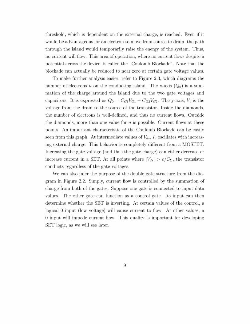


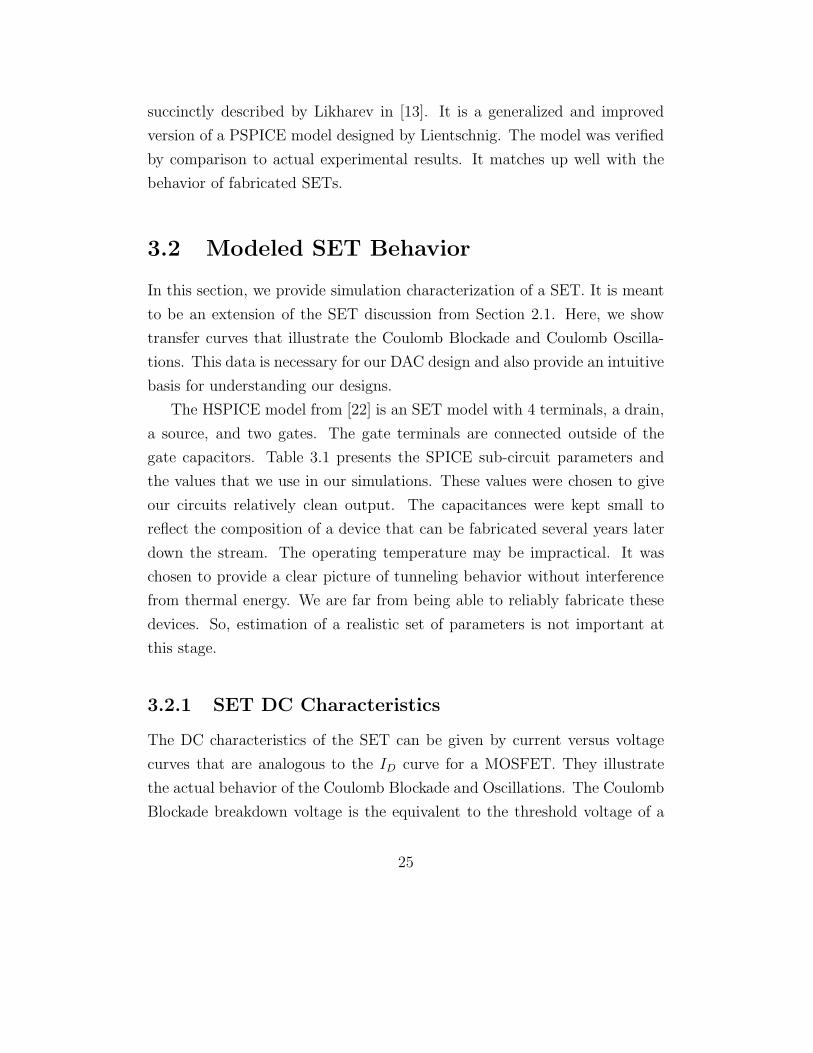


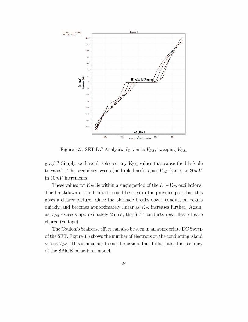

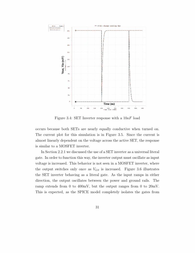

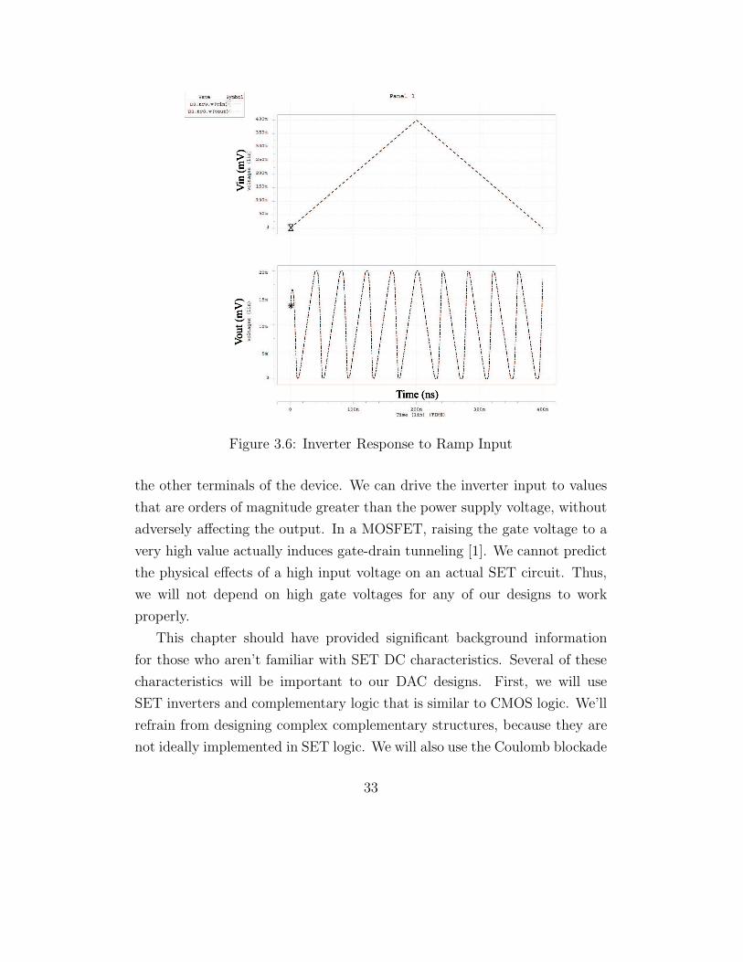


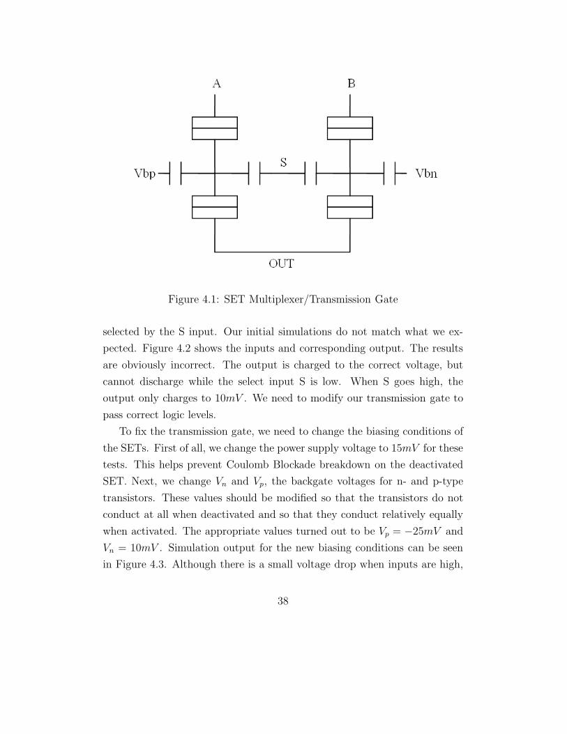

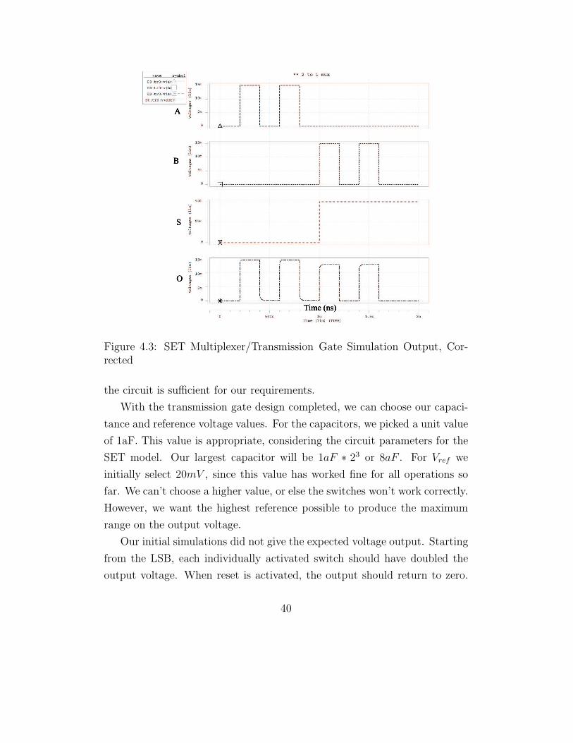


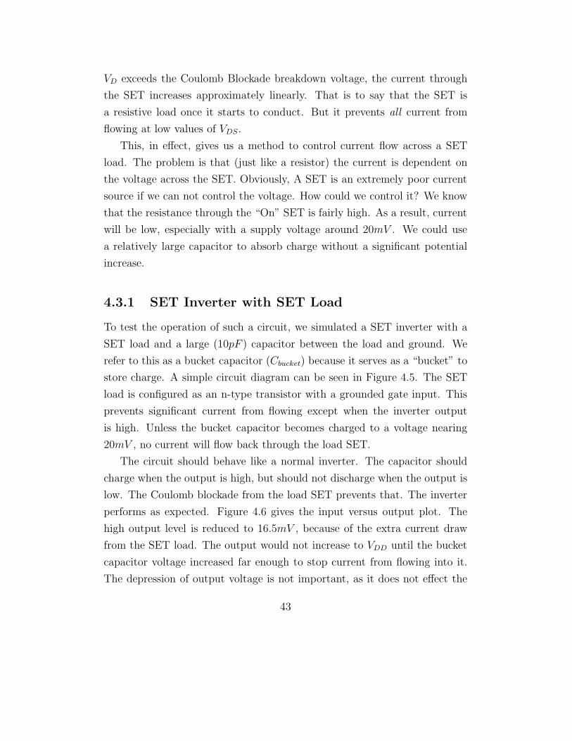


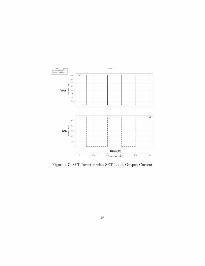


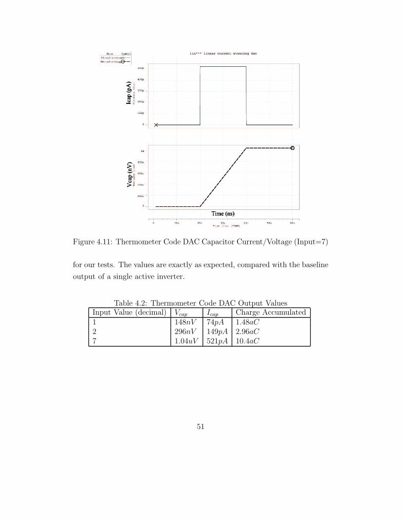


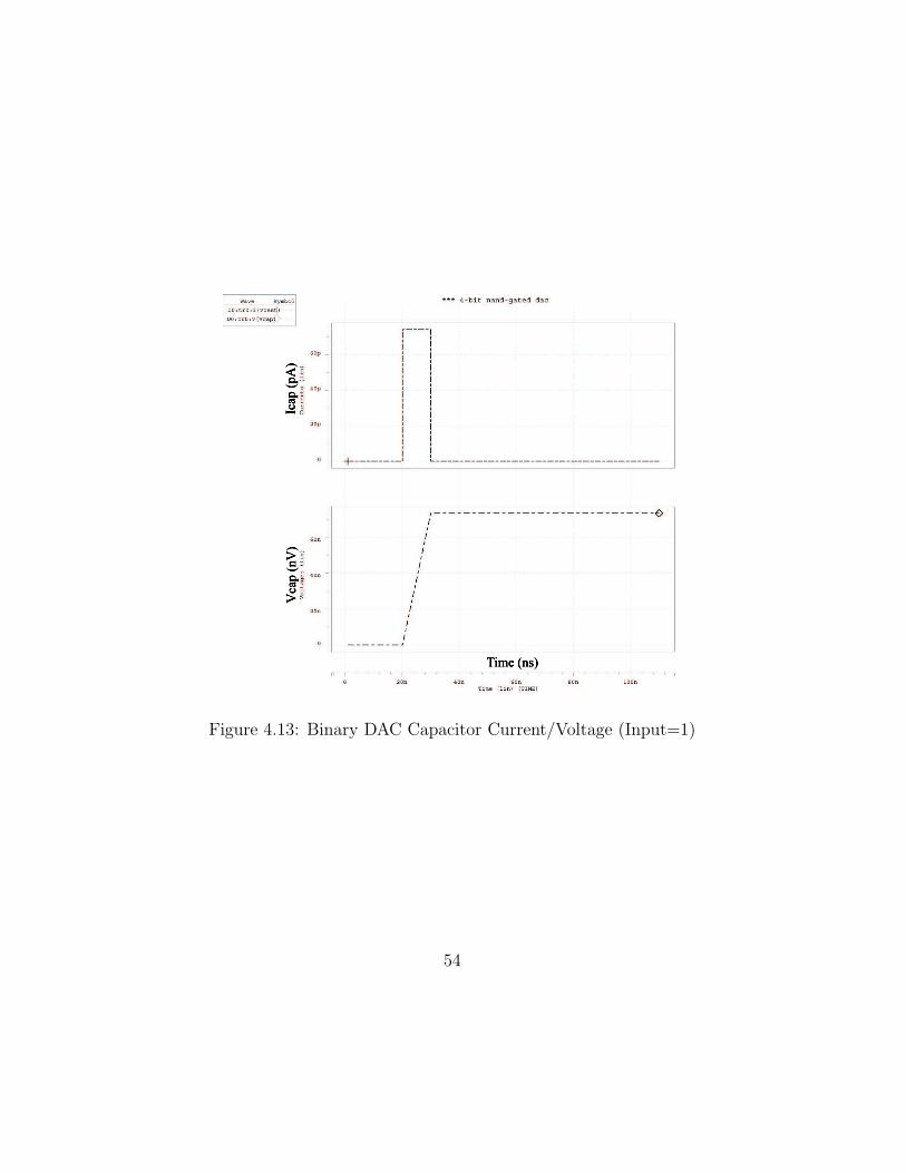
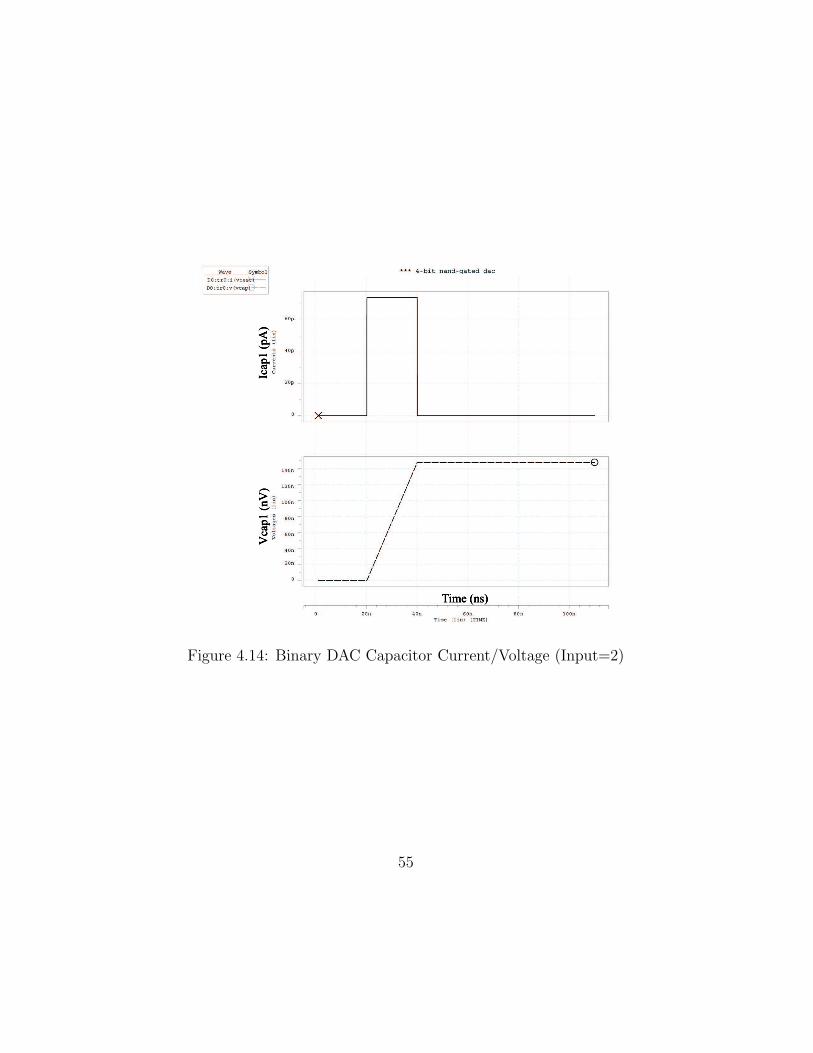


![Iqbal DAC Keynote 061710 - Design Automation … · Computer with GPIB 3.5mm Audio ... DAC 2010 Keynote – Iqbal Arshad ... Iqbal_DAC_Keynote_061710 [Compatibility Mode] Author:](https://static.documents.pub/doc/80x56/5b8a42c17f8b9a50388bc2fa/iqbal-dac-keynote-061710-design-automation-computer-with-gpib-35mm-audio.jpg)
