40
Digital to Mixed-Signal Verification of Power Management SOCs Using Questa-ADMS M. Behaghel
| Date post: | 15-Sep-2018 |
| Category: |
Documents |
| Upload: | vuongtuong |
| View: | 231 times |
| Download: | 3 times |

Digital to Mixed-Signal Verification of Power
Management SOCs Using Questa-ADMS
M. Behaghel

Leading supplier of
platforms and semiconductors
for wireless devices
Fabless company supported
by extensive semiconductor
manufacturing experience
and telecom heritage
Truly global with a
workforce of more than
85% of employees in R&D
A global leader in wireless technologies

Investing to win
Multi-core
architectures,
Low power
consumption
Open OS,
Frameworks
Power
management
and RF
GPS, Bluetooth,
HDMI, Wi-Fi,
USB, FM
3D Graphics, HD
video, audio,
imaging
2G, EDGE, WCDMA,
TD-SCDMA, HSPA,
HSPA+, LTE
A complete portfolio
with multimode
modems, flexible and
scalable solutions
• Leading GPUs
• Power-optimized
multimedia
• Lowest power audio
• Partnership with
STMicroelectronics
• Latest ARM cores
• Optimized process
technologies
• Aggressive nodes
• 40nm Combos
• Integrated
• Interoperability
• True multimode RF
• Architecture &
System level power
design
Connectivity Software
Processors Modem
MultimediaAnalog
& Power
Complete platforms

Outline
∙ AMS/RF Verification: what is the best tradeoff
∙ Modeling
∙ Netlisting Tips: How to fit analog specificities in a digital
mold
∙ Verification of the electrical behavior
∙ Results
10/8/2012CONFIDENTIAL4

AMS/RF Verification
What methodology should we choose?
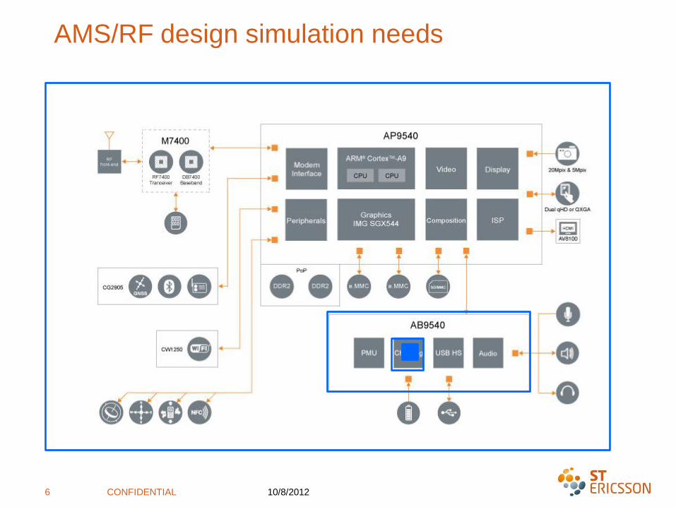
AMS/RF design simulation needs
10/8/2012CONFIDENTIAL6
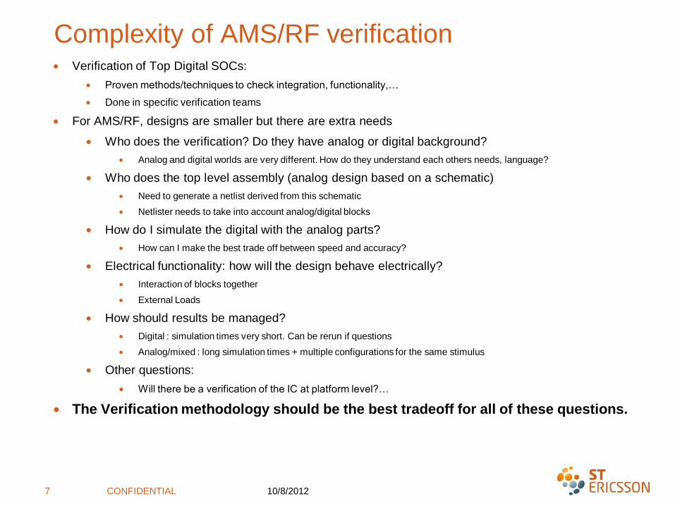
Complexity of AMS/RF verification∙ Verification of Top Digital SOCs:
∙ Proven methods/techniques to check integration, functionality,…
∙ Done in specific verification teams
∙ For AMS/RF, designs are smaller but there are extra needs
∙ Who does the verification? Do they have analog or digital background?
∙ Analog and digital worlds are very different. How do they understand each others needs, language?
∙ Who does the top level assembly (analog design based on a schematic)
∙ Need to generate a netlist derived from this schematic
∙ Netlister needs to take into account analog/digital blocks
∙ How do I simulate the digital with the analog parts?
∙ How can I make the best trade off between speed and accuracy?
∙ Electrical functionality: how will the design behave electrically?
∙ Interaction of blocks together
∙ External Loads
∙ How should results be managed?
∙ Digital : simulation times very short. Can be rerun if questions
∙ Analog/mixed : long simulation times + multiple configurations for the same stimulus
∙ Other questions:
∙ Will there be a verification of the IC at platform level?…
∙ The Verification methodology should be the best tradeoff for all of these questions.
10/8/2012CONFIDENTIAL7
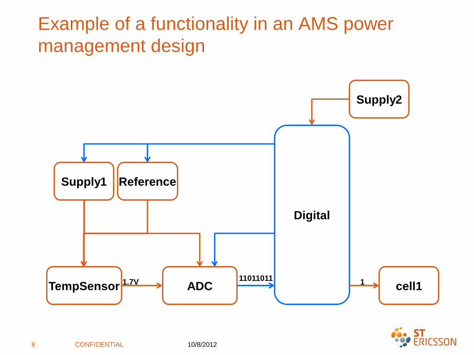
Example of a functionality in an AMS power
management design
10/8/2012CONFIDENTIAL8
ADC
Digital
cell1
Supply1 Reference
Supply2
TempSensor 1.7V11011011
1

What do we want to check in a design?
10/8/2012CONFIDENTIAL9
ADC
Digital
cell1
Supply1 Reference
Supply2
TempSensor1.7V
110110111
Type of errors
Connection errors – wrong signals – wrong power domain
Incorrect buss wires connected
Incorrect register bits used
Misunderstood interface specs – functional issue mismatch
Clock phase-frequency mismatch
Communication / activity during power down.
Delay timing issues. Signals arriving a cycle or two late
Bias mismatch
Current overconsumption
Stability of IP with a real supply especially in startup phases
Electrical behavior like: rise/fall time, loading effects,…..?
Current leakage
Missing level shifter
Floating gate
IP performance, characterization

Mixed
AoT Simulations
(VHDL-AMS)
Simulation flows available today
10/8/2012CONFIDENTIAL10
Analog
Digital
SPICE
Runtime
Fast Slow
Fast SPICE
Full Digital
Fast SPICE
Co-simulations
Mixed
DoT Simulations

Flow Coverage
Type of errors VH
DL
-AM
S
sim
ula
tio
ns
VH
DL
-RN
sim
ula
tio
ns
Do
TM
ixed
sim
ula
tio
ns
Fast-
Sp
ice
co
-sim
ula
tio
n
Sp
ice
sim
ula
tio
n
ER
C
Connection errors – wrong signals – wrong power domain
Incorrect buss wires connected e.g. bit 3, 5, 7 instead of 2, 4, 6
Incorrect register bits used
Misunderstood interface specs – functional issue mismatch
Clock phase-frequency mismatch
Communication / activity during power down.
Delay timing issues. Signals arriving a cycle or two late
Bias mismatch
Current overconsumption
Stability of IP with a real supply especially in startup phases
Electrical performances like: rise/fall time, loading effects,…..?
Current leakage
Missing level shifter
Floating gate
IP performance, caracterisation

Modeling

Modeling: Why do we need models?
∙ To simulate analog behavior with digital blocks
∙ To speed up simulations (clocked blocks)
∙ To do verification in top down approach:
∙ not all of the functionality is implemented yet
∙ Check states that IPs are not intended for:
∙ Connectivity
∙ Power Domain
∙ Biasing
10/8/2012CONFIDENTIAL13
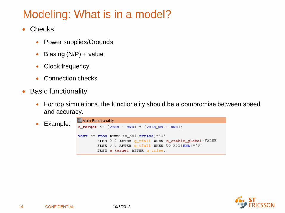
Modeling: What is in a model?
∙ Checks
∙ Power supplies/Grounds
∙ Biasing (N/P) + value
∙ Clock frequency
∙ Connection checks
∙ Basic functionality
∙ For top simulations, the functionality should be a compromise between speed
and accuracy.
∙ Example:
10/8/2012CONFIDENTIAL14
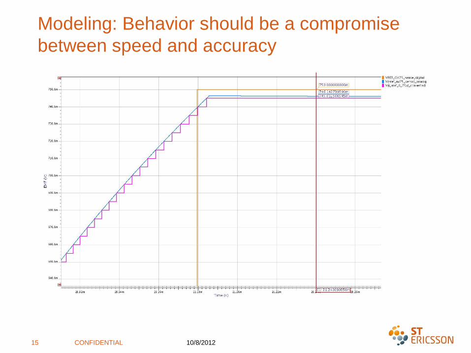
Modeling: Behavior should be a compromise
between speed and accuracy
10/8/2012CONFIDENTIAL15
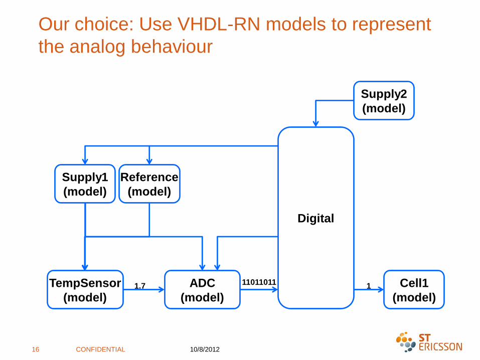
Our choice: Use VHDL-RN models to represent
the analog behaviour
10/8/2012CONFIDENTIAL16
ADC
(model)
Digital
Cell1
(model)
Supply1
(model)
Reference
(model)
Supply2
(model)
TempSensor
(model)1.7
110110111

VHDLRN Modeling Methodology:
VHDL+Real numbers package
∙ Digital pins: type STD_LOGIC
∙ Can be plugged directly to digital blocks
∙ Directions: IN, OUT, INOUT
∙ ANALOG pins : custom resolved type RREAL
∙ Currents and voltages are treated in the same manner
∙ 10.0e-6 for currents and 1.2 for voltage for example.
∙ Currents : + if going to a ground / - if going to a supply
∙ User-defined high impedance value : -10.0
∙ Initial values : -10.0
∙ Netlist: VHDL-RN
10/8/2012CONFIDENTIAL17
Simulations are very fast
No electrical effects. Requires more electrical (fast spice/mixed) simulations
All analog cell need to be modeled

Resolution function
∙ Resolution if value inferior to 1.0e-3 (Current): SUM
∙ Resolution if value superior to 1.0e-3 (Voltage): AVERAGE
∙ High Impedence not taken into account : -10.0 ignored
∙ Possibility to have non controled inouts
10/8/2012CONFIDENTIAL18
VDD_1 VDD_2
Switches
IO ring
Supplies
V1
V1 V1 V1V1
V2
Check V1 = V2
V4
V3
V2
V1
V4
Netlisting Tips
How to fit analog specificities in a digital mold

Netlisting: Analog specificities
∙ Our designs are analog on top. We need to generate a netlist of the design
∙ Several problems:
∙ How can we deal with analog instances that are left on top?
∙ How can we connect types RREAL to STD_LOGIC?
∙ How can we deal with INOUTs
∙ How can we deal with pullup/pulldown, 1 wire communications…
∙ How to check supplies on a digital block?
10/8/2012CONFIDENTIAL20

Netlisting: Analog devices
10/8/2012CONFIDENTIAL21
∙ In VHDL-RN methodology, all components must have a model
∙ Capacitors and Diodes can be removed from the netlist
∙ A resistor can be shorted
∙ A resistor bridge must be modeled

Netlisting: Type conversion functions
∙ Conversion functions are defined in the package (real2stdlogic and stdlogic2real)
∙ They will be inserted automatically by the netlister
MYINST : MYCELL
Port map(
PORT1 => NET1,
PORT2 => real2stdlogic(Net2)
);
10/8/2012CONFIDENTIAL22
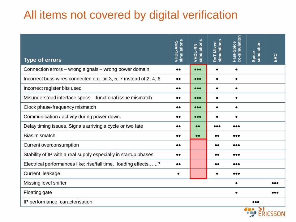
All items not covered by digital verification
Type of errors VH
DL
-AM
S
sim
ula
tio
ns
VH
DL
-RN
sim
ula
tio
ns
Do
TM
ixed
sim
ula
tio
ns
Fast-
Sp
ice
co
-sim
ula
tio
n
Sp
ice
sim
ula
tio
n
ER
C
Connection errors – wrong signals – wrong power domain
Incorrect buss wires connected e.g. bit 3, 5, 7 instead of 2, 4, 6
Incorrect register bits used
Misunderstood interface specs – functional issue mismatch
Clock phase-frequency mismatch
Communication / activity during power down.
Delay timing issues. Signals arriving a cycle or two late
Bias mismatch
Current overconsumption
Stability of IP with a real supply especially in startup phases
Electrical performances like: rise/fall time, loading effects,…..?
Current leakage
Missing level shifter
Floating gate
IP performance, caracterisation

Verification of Electrical Behavior

10/8/2012CONFIDENTIAL25
Mixed simulation for Macrocells Needs
∙ Complement the Digital on top simulations with mixed simulations
∙ Top simulations are based on models: they do not cover analog effects
∙ Need : Simulate the spice behavior of the macrocell in the top environment.
∙ Power-up, power-down : supply stability
∙ Interfaces with other blocks : control currents and voltages, rising time, gain, settling
time
∙ Behavior of the block with a top stimuli
∙ Simulation characteristics:
∙ Transient simulations
∙ Some simulations can have loops between analog and digital

Questa ADMS Platform
ADMS RTL
VHDL/Verilog
Testbench
RTL RTL
SDF
Layout Extraction Schematic
OVM/UVM
Assertions
Coverage
UPF
Eldo Classic
Eldo Premier
ADiT
SPICEAnalog
(RN)
AMS
HDL
DAC 2012 - Questa ADMS Suite Session

VHDL
From digital to mixed simulations
1. Run and optimize the pure
digital simulation inside Questa
ADMS as a sanity check
2. Create the mixed configuration
∙ Converters
∙ Simulation characteristics
∙ Simulator command file
∙ Spice netlists for blocs to be
simulated in analog
3. Run the mixed simulation
10/8/2012CONFIDENTIAL27
Testbench
VHDL/Verilog
VHDL VerilogC
Verilog VHDL Verilog Verilog
VHDL VHDL
Verilog VHDL
VHDL VerilogVerilogSPICE SPICE SPICE
SPICE
VHDL
Configuration
Verilog
GenerateCompilation
Command
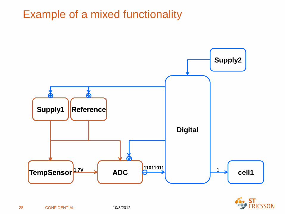
Example of a mixed functionality
10/8/2012CONFIDENTIAL28
ADC
Digital
cell1
Supply1 Reference
Supply2
TempSensor 1.7V 1ADC
Supply1 Reference
TempSensor 1.7V11011011

Automatic converter insertion
∙ Converters are inserted automatically between 2 types:
∙ But the default value may not always be correct:
∙ VOLTAGE/CURRENT converters
∙ Parameters: It may be necessary to change the supply value for digital signals:
∙ D2A_VOLTAGE_STD_LOGIC: ‘1’ VLO=0.0, VHI=1.2
10/8/2012CONFIDENTIAL29
DigitalElectrical ElectricalDigital
STD_LOGIC D2A_VOLTAGE_STD_LOGIC
VHI=1.8; VLO=0.0
A2D_VOLTAGE_STD_LOGIC
VTH1=0.6; VTH2=1.2
RREAL D2A_VOLTAGE_REAL
D2A_CURRENT_REAL
A2D_VOLTAGE_REAL
A2D_CURRENT_REAL
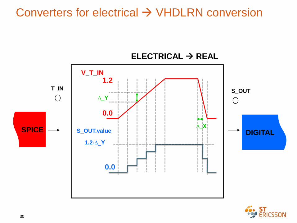
30
ELECTRICAL REAL
SPICE
T_IN S_OUT
DIGITAL
V_T_IN
S_OUT.value
0.0
0.0
∆_X
∆_Y
1.2
1.2-∆_Y
Converters for electrical VHDLRN conversion

Results
Testcases run on a power management SoC

Case 1 : IC startup
∙ Instances generating the mandatory startup powers and controls are
simulated in analog description: SUPPLY1 regulator, REFERENCE,
MONITORING, etc…
∙ Analog content: 12k devices, 5k nodes
10/8/2012CONFIDENTIAL32
Digital
Supply1 Monitor
Reference
cell1 cell1 cell1

Case 1: IC startup - Configuration setup
10/8/2012CONFIDENTIAL33

Case 1: IC Startup - Results
∙ Fast simulation in top level context
-> sanity checks that can be run often
-> enhances confidence in top level behavior
∙ CPU time: 15min Questa ADMS Premier 4CPU
∙ Allows to track bugs that could be missed otherwise
-> found 4 diodes inserted in reverse on the main reference voltage (on the encapsulation of the
IP, so standalone IP simulation could not see it)
-> critical bug highly impacting startup behavior detected during simulation
10/8/2012CONFIDENTIAL34
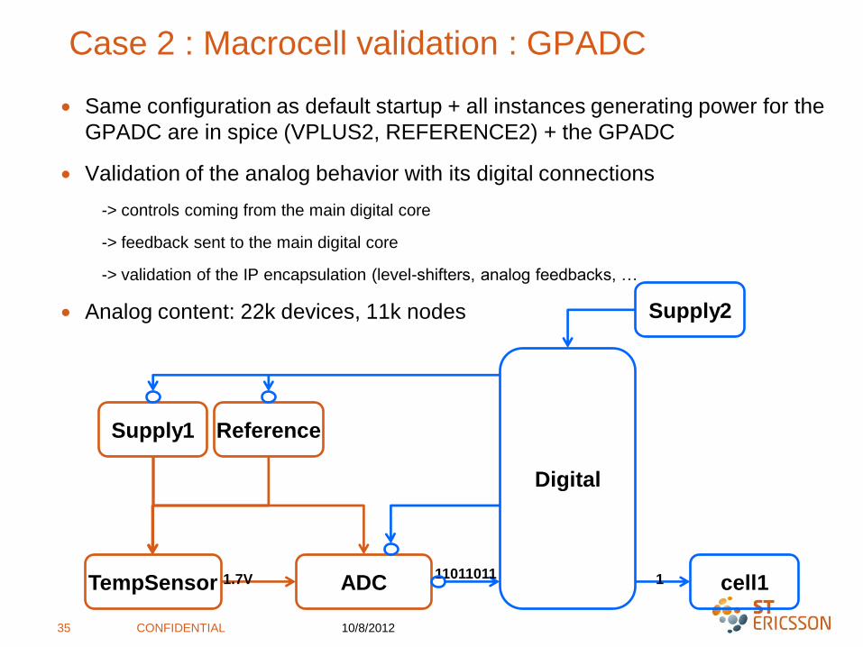
Case 2 : Macrocell validation : GPADC
∙ Same configuration as default startup + all instances generating power for the
GPADC are in spice (VPLUS2, REFERENCE2) + the GPADC
∙ Validation of the analog behavior with its digital connections
-> controls coming from the main digital core
-> feedback sent to the main digital core
-> validation of the IP encapsulation (level-shifters, analog feedbacks, …
∙ Analog content: 22k devices, 11k nodes
10/8/2012CONFIDENTIAL35
ADC
Digital
cell1
Supply1 Reference
Supply2
TempSensor 1.7V 11011011 1

Case 2 : Macrocell validation : GPADC : Results
∙ CPU time: 3h15 Questa ADMS Premier 8CPU
∙ Allows to track bugs that could be missed otherwise
-> found a misalignment in between the digital core and the IP around the DATAREADY behavior,
which caused that the GPADC had 50% of failure on conversion requests!
-> impossible to detect during standalone IP simulation as the controls are generated by the
designer
-> very unlikely to detect during model vs schematic simulation as well, as controls are usually
reused from the standalone IP simulation
-> a critical bug highly impacting the GPADC main behavior detected during simulation
10/8/2012CONFIDENTIAL36

37
Conclusion: Interest of Digital on Top mixed flow
∙ Full digital simulations very fast for
connectivity and functionality verifications
∙ Accuracy depends on model accuracy
∙ Stimuli is the same as a full digital stimuli:
∙ Simulation can be prepared and optimized in digital
∙ The same regression procedures can be used
∙ Possible to switch spice blocks very low in the hierarchy
∙ Possible to use spice or fast spice simulators
∙ Simulations can be done early (does not need spice netlist for all blocks)
∙ A good solution to see details in a design with the accuracy of a spice simulator
ADC
Digital
cell1
Supply1 Reference
Supply2
TempSensor1.7V
110110111

Conclusion: choose the best solution for each
problem
Type of errors VH
DL
-AM
S
sim
ula
tio
ns
VH
DL
-RN
sim
ula
tio
ns
Do
TM
ixed
sim
ula
tio
ns
Fast-
Sp
ice
co
-sim
ula
tio
n
Sp
ice
sim
ula
tio
n
ER
C
Connection errors – wrong signals – wrong power domain
Incorrect buss wires connected e.g. bit 3, 5, 7 instead of 2, 4, 6
Incorrect register bits used
Misunderstood interface specs – functional issue mismatch
Clock phase-frequency mismatch
Communication / activity during power down.
Delay timing issues. Signals arriving a cycle or two late
Bias mismatch
Current overconsumption
Stability of IP with a real supply especially in startup phases
Electrical performances like: rise/fall time, loading effects,…..?
Current leakage
Missing level shifter
Floating gate
IP performance, caracterisation

10/8/2012CONFIDENTIAL39
DISCLAIMER
© Copyright ST-Ericsson, 2009. All Rights Reserved.
The contents of this document are subject to change without prior notice.
ST-Ericsson makes no representation or warranty of any nature whatsoever (neither
expressed nor implied) with respect to the matters addressed in
this document, including but not limited to warranties of merchantability or fitness for a
particular purpose, interpretability or interoperability or, against infringement of third
party intellectual property rights, and in no event shall
ST-Ericsson be liable to any party for any direct, indirect, incidental and or consequential
damages and or loss whatsoever (including but not limited to monetary losses or loss of
data), that might arise from the use of this document or the information in it.
ST-Ericsson and the ST-Ericsson logo are trademarks of the ST-Ericsson group of
companies or used under a license from STMicroelectronics NV or Telefonaktiebolaget
LM Ericsson.
All other names are the property of their respective owners.
For more information on ST-Ericsson, visit www.stericsson.com

THANK YOU


