Digital Video Broadcasting (DVB); Second Generation Common Interface (CI); Part 1: Implementation Using the Universal Serial Bus (USB) DVB Document A173-1 July 2016 NOTE: IMPORTANT WARNING This document is not yet stable. Some incompatible changes may be introduced in the future.
Transcript
Digital Video Broadcasting (DVB); Second Generation Common Interface (CI);
Part 1: Implementation Using the Universal Serial Bus (USB)
DVB Document A173-1
July 2016
NOTE: IMPORTANT WARNING This document is not yet stable.
Some incompatible changes may be introduced in the future.
DVB BlueBook A173-1
3
Contents Contents .............................................................................................................................................................. 3 Intellectual Property Rights ................................................................................................................................ 5 Foreword............................................................................................................................................................. 5 Modal verbs terminology ................................................................................................................................... 5 Introduction ........................................................................................................................................................ 5 Scope 8 1 References ................................................................................................................................................ 9 1.1 Normative references ......................................................................................................................................... 9 1.2 Informative references ....................................................................................................................................... 9 2 Definitions and abbreviations ................................................................................................................. 10 2.1 Definitions ....................................................................................................................................................... 10 2.2 Abbreviations ................................................................................................................................................... 10 3 Mechanical and electrical characteristics ............................................................................................... 10 3.1 Mechanical characteristics ............................................................................................................................... 10 3.1.1 Connector ................................................................................................................................................... 10 3.1.2 Mechanical properties ................................................................................................................................ 10 3.2 Electrical characteristics .................................................................................................................................. 11 4 Module discovery and capabilities description ...................................................................................... 11 4.1 General ............................................................................................................................................................. 11 5 Command interface ................................................................................................................................ 14 5.1 Command endpoints ........................................................................................................................................ 14 5.2 Command data encapsulation .......................................................................................................................... 14 5.2.1 USB transfer format ................................................................................................................................... 14 5.2.2 Example single transfer of 3 300 bytes over 512 byte endpoint (informative) .......................................... 14 5.3 Modification to resources and APDU .............................................................................................................. 14 5.3.1 Introduction ................................................................................................................................................ 14 5.3.2 Application information ............................................................................................................................. 15 5.3.2.1 request_ci_cam_reset APDU ................................................................................................................ 15 5.3.2.2 data_rate_info APDU ........................................................................................................................... 15 5.3.3 Low Speed communication ........................................................................................................................ 15 5.3.4 CAM upgrade ............................................................................................................................................. 15 5.3.4.1 cam_firmware_upgrade_complete APDU ............................................................................................ 15 6 Media interface ....................................................................................................................................... 15 6.1 Introduction...................................................................................................................................................... 15 6.2 Media endpoints ............................................................................................................................................... 16 6.3 Use of USB3.1 bulk streams ............................................................................................................................ 16 6.4 MPEG TS content encapsulation ..................................................................................................................... 16 6.4.1 Mapping MPEG TS packets to fragments .................................................................................................. 16 6.4.2 Protection of MPEG TS content from CICAM to Host ............................................................................. 17 6.5 Sample content encapsulation .......................................................................................................................... 17 6.5.1 Mapping samples to fragments................................................................................................................... 17 6.5.2 Protection of sample content from CICAM to Host ................................................................................... 18 6.5.2.1 Content encryption ............................................................................................................................... 18 6.5.2.2 Native CI+2.0 Encryption..................................................................................................................... 19 6.5.2.3 CI+1.4 Compatible Encryption ............................................................................................................. 19 6.6 Encapsulation rules .......................................................................................................................................... 20 6.7 Fragment header .............................................................................................................................................. 21 6.7.1 Syntax......................................................................................................................................................... 21 6.7.2 Fragment header descriptors ...................................................................................................................... 23 6.7.2.1 General ................................................................................................................................................. 23 6.7.2.2 CI Plus initialization vector descriptor ................................................................................................. 23
DVB BlueBook A173-1
4
6.7.2.3 CI Plus key identifier descriptor ........................................................................................................... 23 6.7.3 Fragment header fields usage (informative) ............................................................................................... 23 7 Networking Interface (NI) ...................................................................................................................... 24 7.1 Introduction...................................................................................................................................................... 24 7.2 Descriptors ....................................................................................................................................................... 25 7.3 USB Control requests ...................................................................................................................................... 25 7.4 Content on the bulk endpoints ......................................................................................................................... 26 7.5 CICAM access to network services ................................................................................................................. 26 7.5.1 IPv4 services .............................................................................................................................................. 26 7.5.2 IPv6 services .............................................................................................................................................. 26 7.5.3 Security and Privacy................................................................................................................................... 26 Annex A (informative): Adapter for first generation CICAMs ........................................................................ 27 A.1 Introduction...................................................................................................................................................... 27 A.2 Adaptation of the command interface .............................................................................................................. 27 A.3 Adaptation of the Transport Stream interface .................................................................................................. 27 Annex B (informative): Providing connectivity with a bridge ......................................................................... 28 B.1 Configuration ................................................................................................................................................... 28 B.2 IGMP snooping description ............................................................................................................................. 29 Annex C (informative): Change History ...................................................................................................... 30 History .............................................................................................................................................................. 30
DVB BlueBook A173-1
5
Intellectual Property Rights IPRs essential or potentially essential to the present document may have been declared to ETSI. The information pertaining to these essential IPRs, if any, is publicly available for ETSI members and non-members, and can be found in ETSI SR 000 314: "Intellectual Property Rights (IPRs); Essential, or potentially Essential, IPRs notified to ETSI in respect of ETSI standards", which is available from the ETSI Secretariat. Latest updates are available on the ETSI Web server (http://ipr.etsi.org).
Pursuant to the ETSI IPR Policy, no investigation, including IPR searches, has been carried out by ETSI. No guarantee can be given as to the existence of other IPRs not referenced in ETSI SR 000 314 (or the updates on the ETSI Web server) which are, or may be, or may become, essential to the present document.
Foreword This Technical Specification (TS) has been produced by Joint Technical Committee (JTC) Broadcast of the European Broadcasting Union (EBU), Comite Europeen de Normalisation ELECtrotechnique (CENELEC) and the European Telecommunications Standards Institute (ETSI).
NOTE: The EBU/ETSI JTC Broadcast was established in 1990 to co-ordinate the drafting of standards in the specific field of broadcasting and related fields. Since 1995 the JTC Broadcast became a tripartite body by including in the Memorandum of Understanding also CENELEC, which is responsible for the standardization of radio and television receivers. The EBU is a professional association of broadcasting organizations whose work includes the co-ordination of its members' activities in the technical, legal, programme-making and programme-exchange domains. The EBU has active members in about 60 countries in the European broadcasting area; its headquarters is in Geneva. European Broadcasting Union CH-1218 GRAND SACONNEX (Geneva) Switzerland Tel: +41 22 717 21 11 Fax: +41 22 717 24 81
The Digital Video Broadcasting Project (DVB) is an industry-led consortium of broadcasters, manufacturers, network operators, software developers, regulatory bodies, content owners and others committed to designing global standards for the delivery of digital television and data services. DVB fosters market driven solutions that meet the needs and economic circumstances of broadcast industry stakeholders and consumers. DVB standards cover all aspects of digital television from transmission through interfacing, conditional access and interactivity for digital video, audio and data. The consortium came together in 1993 to provide global standardization, interoperability and future proof specifications.
The present document is part 1 of a multi-part deliverable covering the Digital Video Broadcasting (DVB); Second Generation Common Interface (CI), as identified below:
x Part 1: “Implementation Using the Universal Serial Bus (USB)”;
x Part 2: “Extensions to the CI Plus™ Specification”.
Modal verbs terminology In the present document "shall", "shall not", "should", "should not", "may", "may not", "need", "need not", "will", "will not", "can" and "cannot" are to be interpreted as described in clause 3.2 of the ETSI Drafting Rules (Verbal forms for the expression of provisions).
"must" and "must not" are NOT allowed in ETSI deliverables except when used in direct citation.
Introduction The DVB Common Interface (DVB-CI) specifications EN 50221 [1] and TS 101 699 [2] describe a system whereby a removable Conditional Access CICAM, given the appropriate rights, unscrambles protected content and routes it back to the Host over the same interface. The DVB Common Interface specifications were extended by the CI Plus
specification [3], developed by CI Plus™ LLP, which provides common methods (i.e. methods that are independent of the up-stream CA system) for mutual authentication of the CICAM and Host, and link encryption over the return interface from the CICAM to the Host. The first generation Common Interface connector was an industry standard PCMCIA slot. The connector for the second generation Common Interface as described in the present document is an industry standard USB Standard-A connector USB 2.0 [5] and USB 3.1 [6].
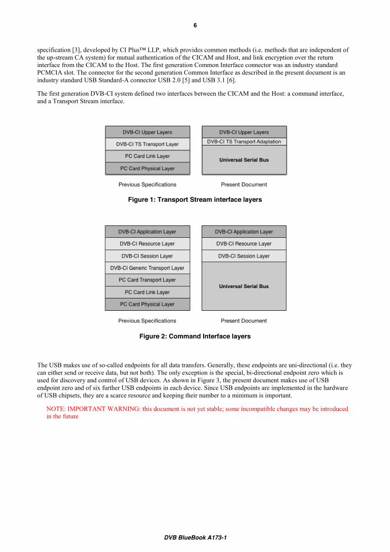
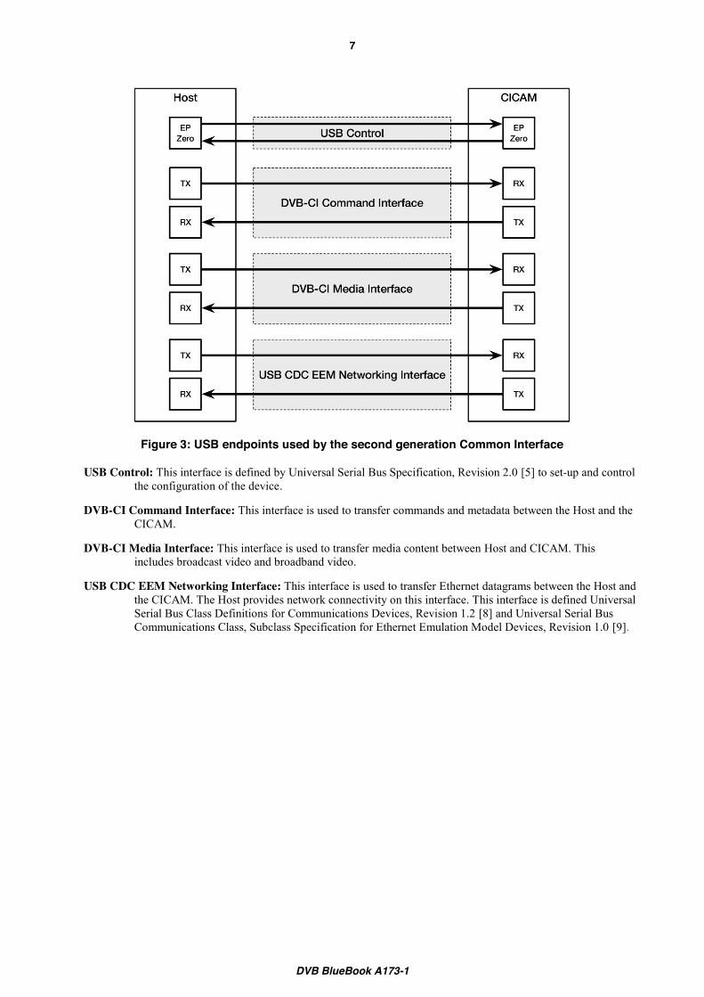
The first generation DVB-CI system defined two interfaces between the CICAM and the Host: a command interface, and a Transport Stream interface.
Figure 1: Transport Stream interface layers
Figure 2: Command Interface layers
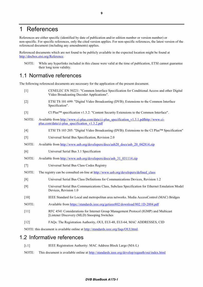
The USB makes use of so-called endpoints for all data transfers. Generally, these endpoints are uni-directional (i.e. they can either send or receive data, but not both). The only exception is the special, bi-directional endpoint zero which is used for discovery and control of USB devices. As shown in Figure 3, the present document makes use of USB endpoint zero and of six further USB endpoints in each device. Since USB endpoints are implemented in the hardware of USB chipsets, they are a scarce resource and keeping their number to a minimum is important.
NOTE: IMPORTANT WARNING: this document is not yet stable; some incompatible changes may be introduced in the future
DVB BlueBook A173-1
7
Figure 3: USB endpoints used by the second generation Common Interface
USB Control: This interface is defined by Universal Serial Bus Specification, Revision 2.0 [5] to set-up and control the configuration of the device.
DVB-CI Command Interface: This interface is used to transfer commands and metadata between the Host and the CICAM.
DVB-CI Media Interface: This interface is used to transfer media content between Host and CICAM. This includes broadcast video and broadband video.
USB CDC EEM Networking Interface: This interface is used to transfer Ethernet datagrams between the Host and the CICAM. The Host provides network connectivity on this interface. This interface is defined Universal Serial Bus Class Definitions for Communications Devices, Revision 1.2 [8] and Universal Serial Bus Communications Class, Subclass Specification for Ethernet Emulation Model Devices, Revision 1.0 [9].
DVB BlueBook A173-1
8
Scope
The present document defines USB physical, link and transport layers for the DVB Common Interface to replace the PC Card interface defined in EN 50221 [1]. The present document also profiles and extends the application layer defined in EN 50221 [1], TS 101 699 [2] and CI Plus specification [3] to cater for the use over USB.
DVB BlueBook A173-1
9
1 References References are either specific (identified by date of publication and/or edition number or version number) or non-specific. For specific references, only the cited version applies. For non-specific references, the latest version of the referenced document (including any amendments) applies.
Referenced documents which are not found to be publicly available in the expected location might be found at http://docbox.etsi.org/Reference.
NOTE: While any hyperlinks included in this clause were valid at the time of publication, ETSI cannot guarantee their long term validity.
1.1 Normative references The following referenced documents are necessary for the application of the present document.
[1] CENELEC EN 50221: "Common Interface Specification for Conditional Access and other Digital Video Broadcasting Decoder Applications".
[2] ETSI TS 101 699: "Digital Video Broadcasting (DVB); Extensions to the Common Interface Specification".
[3] CI Plus™ specification v1.3.2: "Content Security Extensions to the Common Interface".
NOTE: Available from http://www.ci-plus.com/data/ci-plus_specification_v1.3.1.pdfhttp://www.ci-plus.com/data/ci-plus_specification_v1.3.2.pdf
[4] ETSI TS 103 205: "Digital Video Broadcasting (DVB); Extensions to the CI Plus™ Specification"
[5] Universal Serial Bus Specification, Revision 2.0
NOTE: Available from http://www.usb.org/developers/docs/usb20_docs/usb_20_042814.zip
[6] Universal Serial Bus 3.1 Specification
NOTE: Available from http://www.usb.org/developers/docs/usb_31_031114.zip
[7] Universal Serial Bus Class Codes Registry
NOTE: The registry can be consulted on-line at http://www.usb.org/developers/defined_class
[8] Universal Serial Bus Class Definitions for Communications Devices, Revision 1.2
[9] Universal Serial Bus Communications Class, Subclass Specification for Ethernet Emulation Model Devices, Revision 1.0
[10] IEEE Standard for Local and metropolitan area networks. Media AccessControl (MAC) Bridges
NOTE: Available from https://standards.ieee.org/getieee802/download/802.1D-2004.pdf
[11] RFC 4541 Considerations for Internet Group Management Protocol (IGMP) and Multicast [Listener Discovery (MLD) Snooping Switches
[12] FAQs: The Registration Authority, OUI, EUI-48, EUI-64, MAC ADDRESSES, CID
NOTE: this document is available online at http://standards.ieee.org/faqs/OUI.html.
1.2 Informative references [i.1] IEEE Registration Authority: MAC Address Block Large (MA-L)
NOTE: This document is available online at http://standards.ieee.org/develop/regauth/oui/index.html
2 Definitions and abbreviations 2.1 Definitions For the purposes of the present document, the terms and definitions given in [1], [2], [3], [4] apply.
2.2 Abbreviations For the purposes of the present document, the abbreviations given in EN 50221 [1], [2], [3], [4], and the following apply:
MPEG� Moving Pictures Expert Group�CENC Common ENCryption scheme
NOTE: See ISO/IEC 23001-7.
3 Mechanical and electrical characteristics 3.1 Mechanical characteristics 3.1.1 Connector The CICAM shall have a USB 2.0 Standard-A plug as defined in clause 6.5.4 of USB 2.0 [5], or a USB 3.1 Standard-A plug as defined in clause 5.3.1 of USB 3.1 [6].
NOTE: The compatibility between USB 2.0 and USB 3.1 plugs and receptacles is described in clause 5.2.1 of USB 3.1 [6].
Since the Standard-A is the most widespread USB connector type, and as it is interoperable between all versions of USB up to and including 3.1 (the latest version as of this writing), it is expected that future versions of USB retain interoperability with this connector type.
3.1.2 Mechanical properties To be able to be plugged directly into a Host, a CICAM shall not exceed the size limits defined in Table 1. These limits do not include the USB Standard-A plug [5] and USB 3.1 [6]. If a CICAM is designed to not be directly plugged into a Host (e.g. by using a flying lead), it may exceed these size limits. A Host shall provide at least one USB Standard-A receptacle with appropriate spacing to accommodate a CICAM up to the size limits given in Table 1. The USB Standard-A plug [5] and USB 3.1 [6] shall be located as shown in Figure 4. The plug shall be centred relative to dimension W.
Table 1: CICAM size limits
Dimension W D L A Limit 22 mm 12 mm 70 mm <= 1.75 mm
DVB BlueBook A173-1
11
Figure 4: Application of CICAM size limits
NOTE: specification for flying lead can be found in USB 2.0 [5] clause 6.3 and following and in USB 3.1 [6] clause 5.4 and following.
3.2 Electrical characteristics The CICAM shall work within the electrical characteristics defined in USB 2.0 [5] or USB 3.1 [6].
A Host which implements one or more USB 2.0 slots with the mechanical characteristics defined in clause , shall allow for high-power bus-powered functions as defined in clause 7.2.1 of USB 2.0 on these ports.
NOTE: Such devices draw no more than 100 mA upon power-up, and may draw up to 500 mA after being configured.
A Host which implements one or more USB 3.1 slots with the mechanical characteristics defined in clause , shall allow for high-power bus-powered functions as defined in clause 11.4.1 of USB 3.1 on these ports.
NOTE: The amount of current draw for Enhanced SuperSpeed devices is increased to 150 mA for low-power devices and 900 mA for high-power devices when operating at Gen X speed.
4 Module discovery and capabilities description 4.1 General For describing the CICAM during bus enumeration, the following rules shall apply:
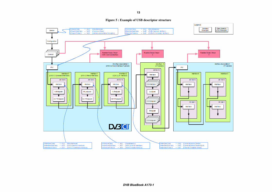
a) In the device descriptor, the CICAM shall report a device Class code of 0xEF, SubClass 0x02, and DeviceProtocol 0x01 to indicate a multi-interface function class, for which the information is given in the Interface Association Descriptor.
b) In each configuration offered by the CICAM, there shall be exactly one Interface Association Descriptor (IAD) for the DVB-CI function.
NOTE: This does not preclude the presence of further IADs for other functions the device may be offering such as for example mass storage.
c) In the Interface Association Descriptor for the DVB-CI function, the CICAM shall report a Class code of 0xEF (miscellaneous class), and SubClass code of 0x07. The CICAM shall report a Protocol code of 0x01 on the Command interface and 0x02 on the Media interface. The Function string shall be set to “DVB Common Interface”.
DVB BlueBook A173-1
12
d) In the Interface Descriptor for the Command Interface (see clause 5) referenced by the IAD for the DVB-CI function, the CICAM shall report a Class code of 0xEF (Miscellaneous device class), and the SubClass and Protocol codes assigned to DVB Common Interface by the USB-IF [7] for this interface. The Interface string shall be set to “DVB-CI Command Interface”.
e) If the CICAM implements the Media Interface (see clause 6), the CICAM shall report a Class code of 0xEF (Miscellaneous device class), and the SubClass and Protocol codes assigned to DVB Common Interface by the USB-IF [7] in the corresponding Interface Descriptor referenced by the IAD for the DVB-CI function. The Interface string shall be set to “DVB-CI Media Interface”.
f) If the CICAM implements the Networking Interfaces (see clause 7), the CICAM shall report the Class, SubClass, and Protocol codes assigned to USB CDC EEM [9] in the corresponding Interface Descriptors referenced by the IAD for the DVB-CI function.
DVB BlueBook A173-1
13
Figure 5 : Example of USB descriptor structure
ETSI
ETSI TS 1xx xxx-1 V1.1.1 (2016-06) 14 or [Release #]
5 Command interface 5.1 Command endpoints CICAM Interface shall contain two endpoints for command transfer: one bulk IN endpoint and one bulk OUT endpoint. Endpoint sizes shall be at least 64 bytes for transfer efficiency.
NOTE: A 64 byte endpoint size with 1 USB packet transferred per micro frame gives around 4Mbit/s transfer rate which is above the required 3.5 Mbit/s for PCMCIA DVB-CI command interface (see clause 5.4.2 of EN 50221 [1]).
5.2 Command data encapsulation 5.2.1 USB transfer format Data transferred over command endpoints shall be SPDUs as defined by EN 50221 [1] Chapter 7.2 Session Layer. Data can be either a standalone SPDU (Topen_session_request, Topen_session_response, Tclose_session_request, Tclose_session_response) or an SPDU Tsession_number followed by an APDU.
Tcreate_session_request and Tcreate_session_response SPDUs shall not be used. DVB CI Resources provided by the CICAM are no longer supported.
A USB transfer on this interface shall contain exactly one SPDU. The SPDU may be a standalone session header or a session header followed by an APDU. This interface uses short or zero length packets to indicate the end of transfer. Hence the last, and only the last, packet of a USB transfer shall be either a short or a zero length packet (USB2.0 [5] section 5.8.3).
NOTE: CENELEC EN 50221 [1] clause 7.2 allows more than one APDU per SPDU. The present document restricts it to a single one.
NOTE: The transport layer as defined in CENELEC EN 50221 [1] clause 7.1 is not used by the present document. Hence no transport connection establishment is needed. The Poll mechanism of transport layer is not required anymore since the CAM can actively send data over the IN endpoint.
5.2.2 Example single transfer of 3 300 bytes over 512 byte endpoint (informative)
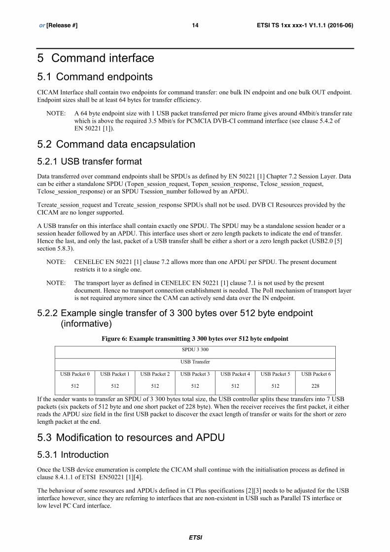
Figure 6: Example transmitting 3 300 bytes over 512 byte endpoint SPDU 3 300
USB Transfer
USB Packet 0
512
USB Packet 1
512
USB Packet 2
512
USB Packet 3
512
USB Packet 4
512
USB Packet 5
512
USB Packet 6
228
If the sender wants to transfer an SPDU of 3 300 bytes total size, the USB controller splits these transfers into 7 USB packets (six packets of 512 byte and one short packet of 228 byte). When the receiver receives the first packet, it either reads the APDU size field in the first USB packet to discover the exact length of transfer or waits for the short or zero length packet at the end.
5.3 Modification to resources and APDU 5.3.1 Introduction Once the USB device enumeration is complete the CICAM shall continue with the initialisation process as defined in clause 8.4.1.1 of ETSI EN50221 [1][4].
The behaviour of some resources and APDUs defined in CI Plus specifications [2][3] needs to be adjusted for the USB interface however, since they are referring to interfaces that are non-existent in USB such as Parallel TS interface or low level PC Card interface.
ETSI
ETSI TS 1xx xxx-1 V1.1.1 (2016-06) 15 or [Release #]
5.3.2 Application information 5.3.2.1 request_ci_cam_reset APDU
This APDU, defined in CI Plus specification [3] clause 11.1.2, shall not be sent by the CICAM.
NOTE: The CICAM can reset itself and force a re-enumeration at USB level as specified in USB 2.0 [5] clause 9.1.
NOTE: This APDU was introduced with version 3 of the resource in CI Plus specification [3].
5.3.2.2 data_rate_info APDU
This APDU, defined in CI Plus specification [3] clause 11.1.3.1, shall not be sent by the Host.
NOTE: This APDU was introduced with version 3 of the resource in CI Plus specification [3].
5.3.3 Low Speed communication This resource, defined in CI Plus specification [3] clause 14.1 and 14.2, shall not be offered by the Host. IP communication shall instead happen over the USB CDC EEM Networking Interface defined in this document at clause 7
This APDU is defined in CI Plus specification [3] clause 14.3.5.5. The reset_request_status field shall be ignored by the Host.
NOTE: The CICAM can reset itself and force a re-enumeration at USB level as specified in USB 2.0 [5] clause 9.1
6 Media interface 6.1 Introduction A CICAM may offer one or more media interfaces as defined in the present clause.
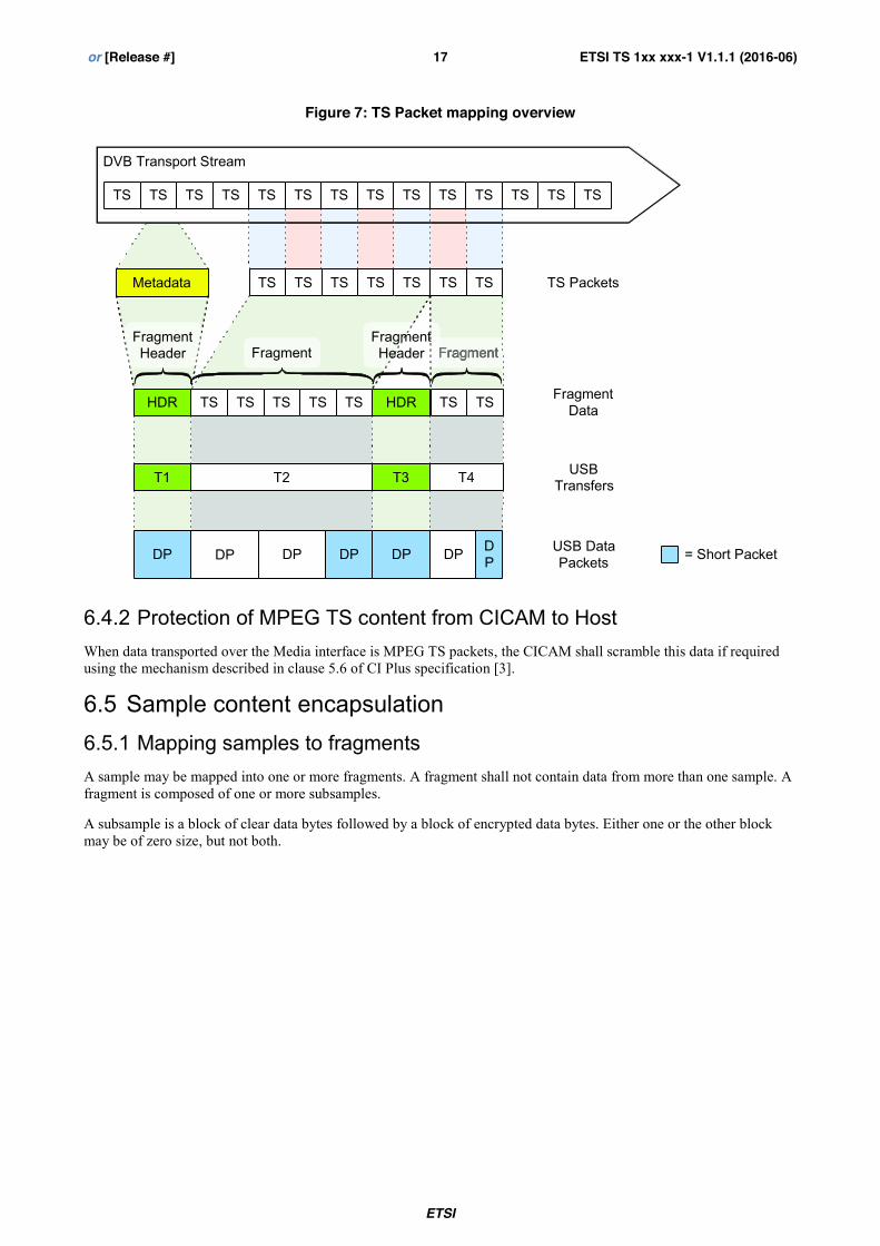
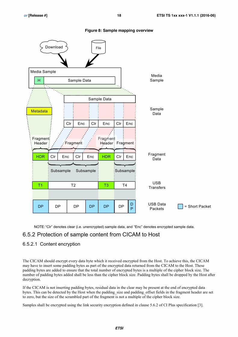
As shown in Figure 8, ISOBMFF samples or MPEG TS packets shall be mapped into one or more fragments according to clauses 6.4 and 6.5, using a fragment header (which is defined in clause 6.7) preceding each fragment. These fragments shall be sent over Media endpoints (which are defined in clause 6.2). Fragment data sent from the CICAM to the Host shall be protected according to clause 6.4.2 and 6.5.2.
The content of the fragment is determined depending on the latest APDU received that relates to the corresponding LTS_id as specified in table 2.
As operations on the command and media interfaces are not synchronised, when transitioning from one scenario to another Host and CICAM shall be ready to receive residual data from the previous scenario, or to initially miss some data from the next scenario. Hence when the CICAM receives data with an LTS_id for which the format is unknown or not matching the active scenario, it may discard this data.
ETSI
ETSI TS 1xx xxx-1 V1.1.1 (2016-06) 16 or [Release #]
Table 2 Format of media data according to application layer information
Command Scenario Data Format
ca_pmt Broadcast MPEG TS packets
sd_start with ts_flag=1 IP delivery Host player mode with TS content MPEG TS packets
sd_start with ts_flag=0 IP delivery Host player mode with non-TS content
ISOBMFF samples
CICAM_player_start_reply “IP delivery” CICAM player mode MPEG TS packets
(CICAM to Host only)
6.2 Media endpoints A CICAM media interface shall offer one pair of media interface stream endpoints.
Media endpoint sizes shall be at least 128 bytes for transfer efficiency.
For the highest transfer efficiency, it is recommended that the CICAM supports the maximum possible endpoint size.
NOTE: For USB 2 the maximum endpoint size is 512 bytes and for USB 3 the maximum endpoint size is 1 024 bytes.
The media endpoints shall be described by the following descriptors:
1) An OUT endpoint descriptor as defined in USB2 clause 9.6.6 of USB 2.0 [5].
2) An IN endpoint descriptor as defined in USB2 clause 9.6.6 USB 2.0 [5].
Both the IN and OUT Endpoint descriptors shall have bmAttributes[1:0] = 0b10 to indicate that they are bulk endpoints.
6.3 Use of USB3.1 bulk streams If the device supports bulk streams and the Host chooses to use them, data for an LTS_id shall only be carried with a single bulk Stream ID. A bulk stream may carry data for more than one LTS_id, however. The CICAM shall not change the LTS_id to bulk Stream ID mapping when returning data received from the Host. For the CAM player modes, the CICAM may use additional LTS_ids and bulk Stream IDs for data it originates.
NOTE: A Host may use bulk streams, for instance, to group similar data streams (e.g. all broadcast streams), or to separate streams which may have different processing delays.
6.4 MPEG TS content encapsulation 6.4.1 Mapping MPEG TS packets to fragments MPEG TS fragments shall be composed of an integral number of MPEG TS packets from the same local transport stream.
ETSI
ETSI TS 1xx xxx-1 V1.1.1 (2016-06) 17 or [Release #]
Figure 7: TS Packet mapping overview
6.4.2 Protection of MPEG TS content from CICAM to Host When data transported over the Media interface is MPEG TS packets, the CICAM shall scramble this data if required using the mechanism described in clause 5.6 of CI Plus specification [3].
6.5 Sample content encapsulation 6.5.1 Mapping samples to fragments A sample may be mapped into one or more fragments. A fragment shall not contain data from more than one sample. A fragment is composed of one or more subsamples.
A subsample is a block of clear data bytes followed by a block of encrypted data bytes. Either one or the other block may be of zero size, but not both.
DVB Transport Stream
DP DP
HDR HDR
USB Data Packets
Metadata
T1 T2 T3 T4 USB Transfers
DP DP DP DP DP
TS Packets
= Short Packet
Fragment
Fragment Data
Fragment Header Fragment
TSTSTSTSTS
TSTSTS TS TSTS TS
TSTS
TS TSTS TS TS TSTS TS TSTS TSTSTSTS
FragmentFragment Header
ETSI
ETSI TS 1xx xxx-1 V1.1.1 (2016-06) 18 or [Release #]
6.5.2 Protection of sample content from CICAM to Host 6.5.2.1 Content encryption
The CICAM should encrypt every data byte which it received encrypted from the Host. To achieve this, the CICAM may have to insert some padding bytes as part of the encrypted data returned from the CICAM to the Host. These padding bytes are added to ensure that the total number of encrypted bytes is a multiple of the cipher block size. The number of padding bytes added shall be less than the cipher block size. Padding bytes shall be dropped by the Host after decryption.
If the CICAM is not inserting padding bytes, residual data in the clear may be present at the end of encrypted data bytes. This can be detected by the Host when the padding_size and padding_offset fields in the fragment header are set to zero, but the size of the scrambled part of the fragment is not a multiple of the cipher block size.
Samples shall be encrypted using the link security encryption defined in clause 5.6.2 of CI Plus specification [3].
Clr EncClr EncClrEnc Sample Data
Media Sample
DP DP
HDR HDR
USB Data Packets
FileDownload
Metadata
Sample DataH
T1 T2 T3 T4 USB Transfers
DP DP DP DP DP
Sample Data
Media Sample
= Short Packet
EncClr EncClr EncClr
EncClr EncClr EncClr
Subsample
Fragment
Fragment Data
Subsample Subsample
Fragment Header
Fragment Header
Fragment Fragment
ETSI
ETSI TS 1xx xxx-1 V1.1.1 (2016-06) 19 or [Release #]
CI+1.4 compatible encryption may be used by USB to PCCard adapter to adapt the encryption used by PCMCIA based CICAM. The CI+2.0 native encryption may be used by a native CI+2.0 to reduce the processing overhead.
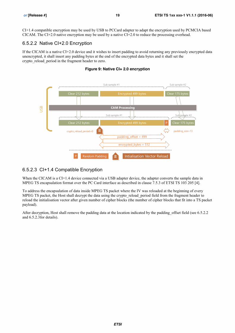
6.5.2.2 Native CI+2.0 Encryption
If the CICAM is a native CI+2.0 device and it wishes to insert padding to avoid returning any previously encrypted data unencrypted, it shall insert any padding bytes at the end of the encrypted data bytes and it shall set the crypto_reload_period in the fragment header to zero.
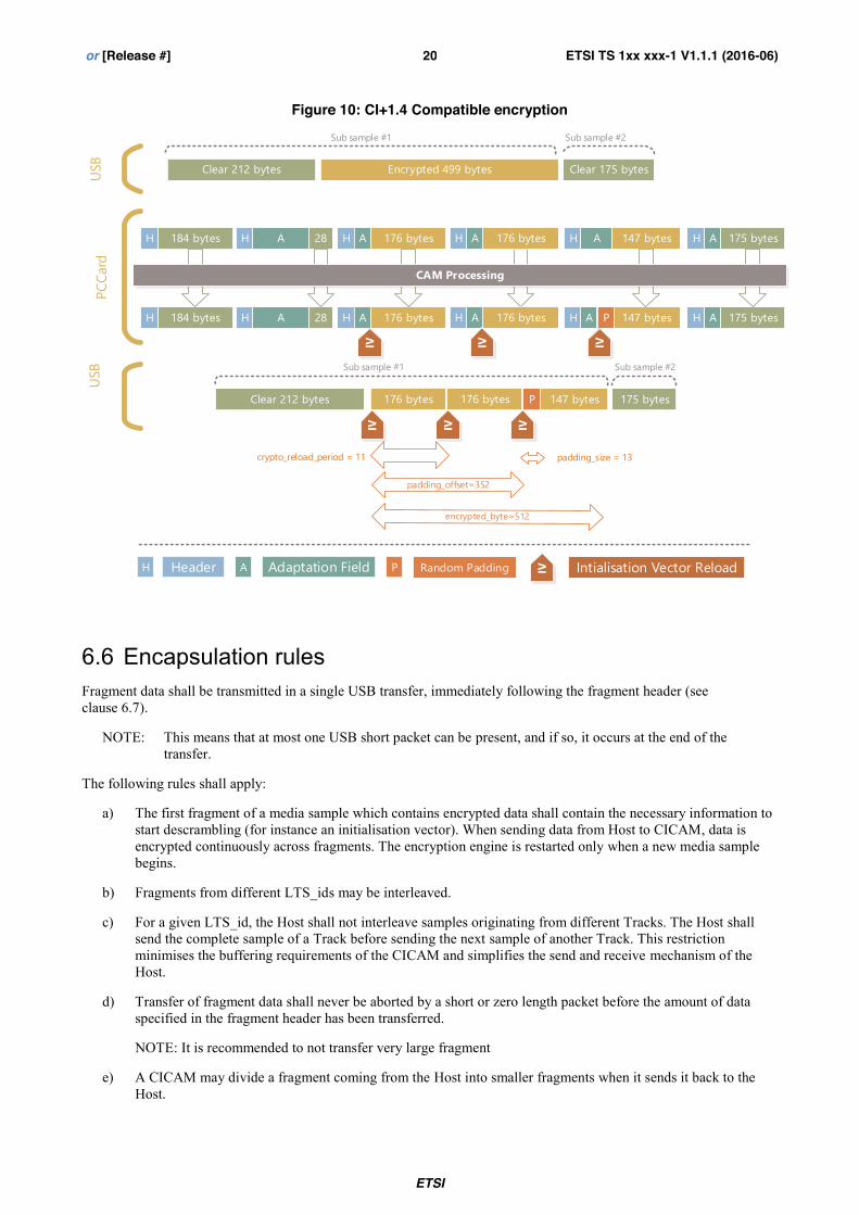
When the CICAM is a CI+1.4 device connected via a USB adapter device, the adapter converts the sample data in MPEG TS encapsulation format over the PC Card interface as described in clause 7.5.3 of ETSI TS 103 205 [4].
To address the encapsulation of data inside MPEG TS packet where the IV was reloaded at the beginning of every MPEG TS packet, the Host shall decrypt the data using the crypto_reload_period field from the fragment header to reload the initialisation vector after given number of cipher blocks (the number of cipher blocks that fit into a TS packet payload).
After decryption, Host shall remove the padding data at the location indicated by the padding_offset field (see 6.5.2.2 and 6.5.2.3for details).
ETSI
ETSI TS 1xx xxx-1 V1.1.1 (2016-06) 20 or [Release #]
184 bytesH AH 28 H 176 bytesA H A 147 bytes AH 175 bytes
184 bytesH AH 28 H 176 bytesA H A 147 bytes AH 175 bytes
CAM Processing
P
Clear 212 bytes 176 bytes P 147 bytes 175 bytes
IV IV
IV IV
PCCa
rdUS
BUS
B
padding_offset=352
Sub sample #1
Sub sample #1
Sub sample #2
Sub sample #2
H 176 bytesA
H 176 bytesA
IV
176 bytes
IV
H A P IVHeader Adaptation Field Random Padding Intialisation Vector Reload
padding_size = 13crypto_reload_period = 11
6.6 Encapsulation rules Fragment data shall be transmitted in a single USB transfer, immediately following the fragment header (see clause 6.7).
NOTE: This means that at most one USB short packet can be present, and if so, it occurs at the end of the transfer.
The following rules shall apply:
a) The first fragment of a media sample which contains encrypted data shall contain the necessary information to start descrambling (for instance an initialisation vector). When sending data from Host to CICAM, data is encrypted continuously across fragments. The encryption engine is restarted only when a new media sample begins.
b) Fragments from different LTS_ids may be interleaved.
c) For a given LTS_id, the Host shall not interleave samples originating from different Tracks. The Host shall send the complete sample of a Track before sending the next sample of another Track. This restriction minimises the buffering requirements of the CICAM and simplifies the send and receive mechanism of the Host.
d) Transfer of fragment data shall never be aborted by a short or zero length packet before the amount of data specified in the fragment header has been transferred.
NOTE: It is recommended to not transfer very large fragment
e) A CICAM may divide a fragment coming from the Host into smaller fragments when it sends it back to the Host.
ETSI
ETSI TS 1xx xxx-1 V1.1.1 (2016-06) 21 or [Release #]
f) A CICAM shall not merge together multiple fragments coming from the Host into bigger fragments when it sends them back to the Host.
For optimal operations the following recommendation should be followed:
a) Fragments should contain 40 to 50 ms of content playtime to reduce system load without impairing channel change time.
b) Whenever possible, the Host should filter the TS sent to the CICAM as defined in clause 6.3 of ETSI TS 103 205 [4], to minimize system load and bandwidth usage.
6.7 Fragment header 6.7.1 Syntax A fragment header shall precede each fragment. This header shall be contained in a single USB transfer, and no other data shall be present in that USB transfer. Each fragment header shall be followed by a fragment.
} descriptor_length 16 uimsbf for (i=0;i<N;i++) { descriptor() } }
Semantics of fields in the fragment header:
protocol_version: This 8-bit field indicates the version of the syntax according to which this fragment header has been encoded. For current version of the present document this shall be set to zero.
LTS_id: This 8-bit field identifies an MPEG transport stream or, together with the track_id a sample track.
NOTE: Whether an LTS uses MPEG transport stream or sample data format is coordinated by the resources on the command interface. Hence the data format in use can be inferred from LTS_id.
track_id: This 8-bit field together with the LTS_id identifies a sample track. This field shall be set to zero when the data format is MPEG transport stream.
ETSI
ETSI TS 1xx xxx-1 V1.1.1 (2016-06) 22 or [Release #]
flush: When this 1 bit field is set to 1 by the Host, the CICAM shall remove from its buffer all the data received for this LTS_id before the present fragment header. The CICAM shall acknowledge the flush by returning the fragment header with the flush bit set to 1 on the first fragment after the completion of the flush operation.
In sample mode, when the flush bit is set to 1 in a header, the following fragment shall be the start of a new sample.
The Host may start the transmission of some new samples after setting the flush bit to 1 without having to wait for the CICAM’s acknowledgement. The Host shall not assume that the flush has been completed and that the CICAM buffer has been flushed until it receives the CICAM’s acknowledgement.
In CICAM player mode the CICAM may also set this flag to 1 to instruct the Host to remove from its buffer all the data received for this LTS_id before the present fragment header. The Host does not reply to the CICAM to confirm completion of the flush. The flush shall be treated by the Host as a discontinuity in the stream where media parameters can change (format, video size, frame rate, etc.).
first_fragment: This 1-bit field indicates the start of a sample. When set to 1, the following fragment data shall be the start of a new sample. When the format of data is MPEG transport stream, it shall always be set to 0.
last_fragment: This 1-bit field indicates the end of a sample. When set to 1, the following fragment data shall be the last data for the sample. When the format of data is MPEG transport stream it shall always be set to 0.
number_subsamples: This 32-bit field indicates the number of subsamples in the fragment. This field shall be set to zero if and only if the data format is MPEG transport stream.
clear_bytes: This 16-bit field indicates the size of the clear data at the beginning of the subsample.
encrypted_bytes: This 16-bit field indicates the size of the encrypted data following the clear data. This number includes any padding data added by the CICAM.
crypto_reload_period: This 8-bit field indicates the number of cipher blocks of encrypted data after which the initialisation vector is reloaded when decrypting subsample encrypted data. When set to 0, the initialisation vector is loaded only at the beginning of the encrypted subsample data. When using AES encryption, the only non-zero valid value is 11. When using DES encryption, the only non-zero valid value is 23. This field shall only be used in CICAM to Host transfers. For Host to CICAM transfers, this field shall be set to 0.
scrambling_control: This 2-bit field indicates which scrambling key is used to encrypt the encrypted bytes of the subsample data in transfers from the CICAM to the Host where the content is Media Sample. In this case, this field shall be set to the same values as defined in clause 5.6.1 of CI Plus specification [3] for the transport scrambling control bits of Transport Stream packets. In all other cases this field shall be set to zero.
padding_size: This 6-bit field indicates the size in bytes of random padding data added to the encrypted data to ensure its length is an integral number of cipher blocks. This field shall only be used in CICAM to Host transfers. For Host to CICAM transfers, this field shall be set to 0. See section 6.5.2
padding_offset: This 16-bit field indicates the number of encrypted bytes before the padding. See section 6.5.2
descriptor_length: This 16-bit field indicates the number of descriptor bytes following. Only the descriptors defined in clause 6.7.2 have defined semantics.
The following rules shall apply when encoding the above fields:
a) If the sample has no clear bytes, number_subsamples shall be set to 1, clear_bytes shall be set to zero and encrypted_bytes shall be set to the size of the sample.
b) If the sample has no encrypted bytes, number_subsamples shall be set to 1, clear_bytes shall be set to the size of the sample and encrypted_bytes shall be set to zero.
Example: When a sample is protected using MPEG CENC and has subsample_count set to 0, implying that all bytes of this sample are either clear or encrypted.
ETSI
ETSI TS 1xx xxx-1 V1.1.1 (2016-06) 23 or [Release #]
6.7.2 Fragment header descriptors 6.7.2.1 General
This clause defines the descriptors that may be used within fragment headers. Zero or more of these descriptors may be inserted into the fragment headers specified in clause 6.7.1 as the construct "descriptor ()".
The semantics defined in ETSI TS 103 205 [4] clause 7.5.5.4 apply to all of the descriptors.
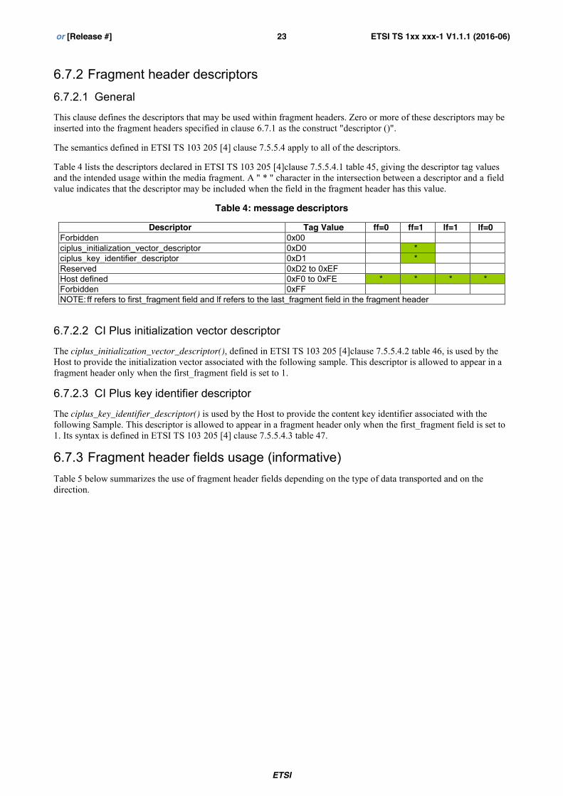
Table 4 lists the descriptors declared in ETSI TS 103 205 [4]clause 7.5.5.4.1 table 45, giving the descriptor tag values and the intended usage within the media fragment. A " * " character in the intersection between a descriptor and a field value indicates that the descriptor may be included when the field in the fragment header has this value.
Table 4: message descriptors
Descriptor Tag Value ff=0 ff=1 lf=1 lf=0 Forbidden 0x00 ciplus_initialization_vector_descriptor 0xD0 * ciplus_key_identifier_descriptor 0xD1 * Reserved 0xD2 to 0xEF Host defined 0xF0 to 0xFE * * * * Forbidden 0xFF NOTE: ff refers to first_fragment field and lf refers to the last_fragment field in the fragment header
6.7.2.2 CI Plus initialization vector descriptor
The ciplus_initialization_vector_descriptor(), defined in ETSI TS 103 205 [4]clause 7.5.5.4.2 table 46, is used by the Host to provide the initialization vector associated with the following sample. This descriptor is allowed to appear in a fragment header only when the first_fragment field is set to 1.
6.7.2.3 CI Plus key identifier descriptor
The ciplus_key_identifier_descriptor() is used by the Host to provide the content key identifier associated with the following Sample. This descriptor is allowed to appear in a fragment header only when the first_fragment field is set to 1. Its syntax is defined in ETSI TS 103 205 [4] clause 7.5.5.4.3 table 47.
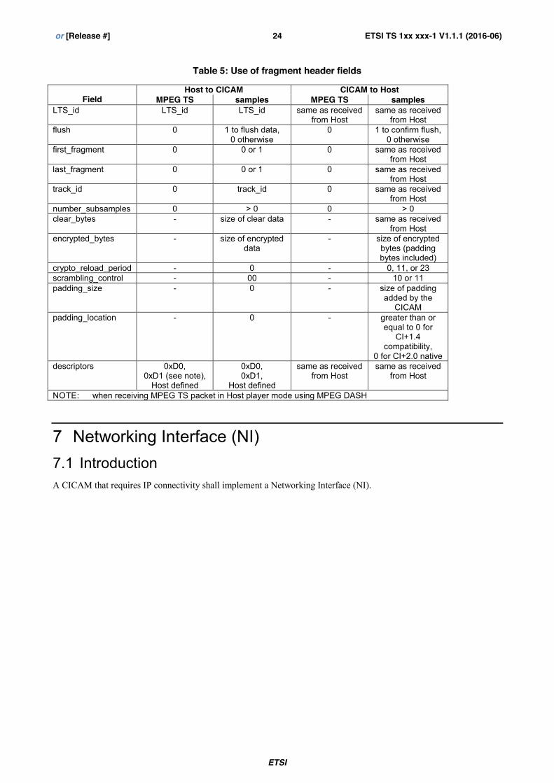
6.7.3 Fragment header fields usage (informative) Table 5 below summarizes the use of fragment header fields depending on the type of data transported and on the direction.
ETSI
ETSI TS 1xx xxx-1 V1.1.1 (2016-06) 24 or [Release #]
Table 5: Use of fragment header fields
Field
Host to CICAM CICAM to Host MPEG TS samples MPEG TS samples
LTS_id LTS_id LTS_id same as received from Host
same as received from Host
flush 0 1 to flush data, 0 otherwise
0 1 to confirm flush, 0 otherwise
first_fragment 0 0 or 1 0 same as received from Host
last_fragment 0 0 or 1 0 same as received from Host
track_id 0 track_id 0 same as received from Host
number_subsamples 0 > 0 0 > 0 clear_bytes - size of clear data - same as received
from Host encrypted_bytes - size of encrypted
data - size of encrypted
bytes (padding bytes included)
crypto_reload_period - 0 - 0, 11, or 23 scrambling_control - 00 - 10 or 11 padding_size - 0 - size of padding
added by the CICAM
padding_location - 0 - greater than or equal to 0 for
CI+1.4 compatibility,
0 for CI+2.0 native descriptors 0xD0,
0xD1 (see note), Host defined
0xD0, 0xD1,
Host defined
same as received from Host
same as received from Host
NOTE: when receiving MPEG TS packet in Host player mode using MPEG DASH
7 Networking Interface (NI) 7.1 Introduction A CICAM that requires IP connectivity shall implement a Networking Interface (NI).
ETSI
ETSI TS 1xx xxx-1 V1.1.1 (2016-06) 25 or [Release #]
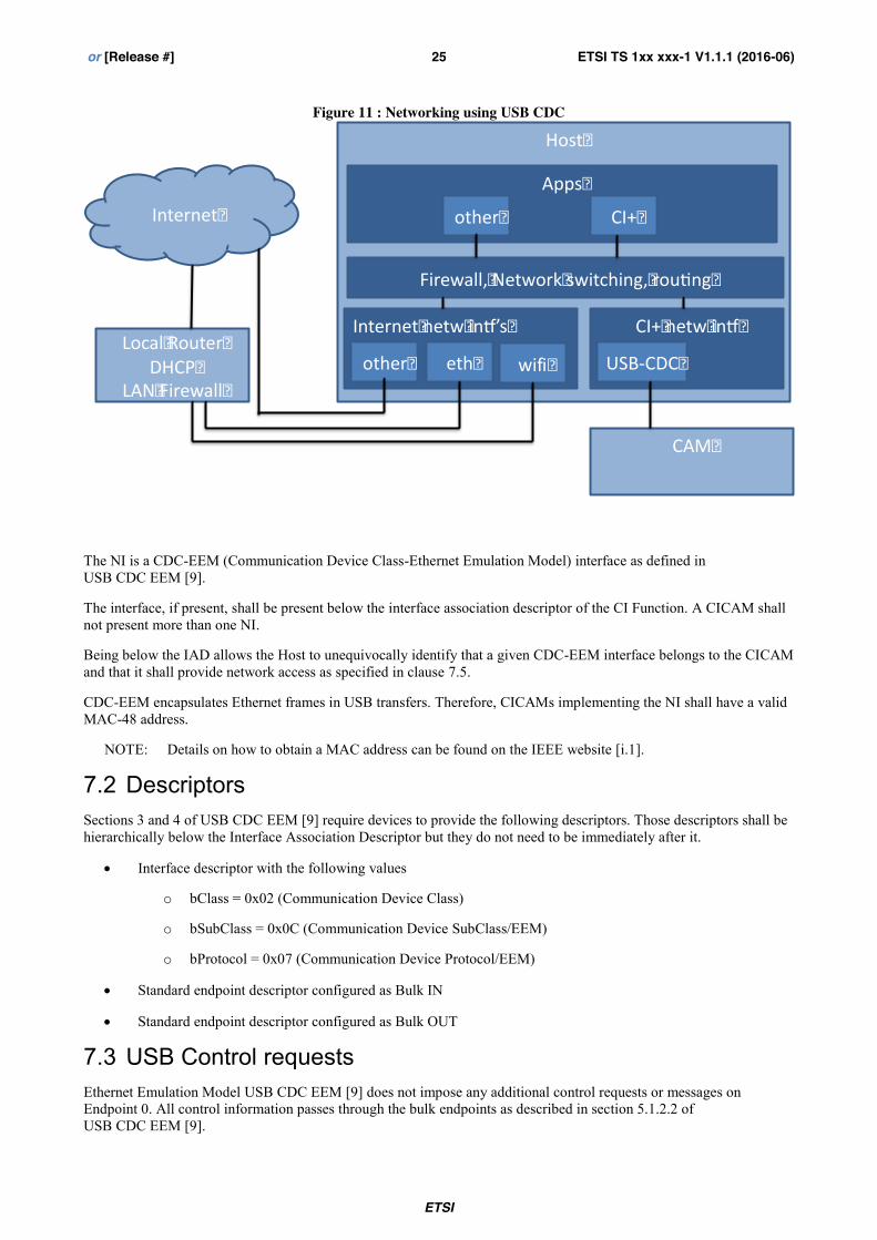
Figure 11 : Networking using USB CDC
The NI is a CDC-EEM (Communication Device Class-Ethernet Emulation Model) interface as defined in USB CDC EEM [9].
The interface, if present, shall be present below the interface association descriptor of the CI Function. A CICAM shall not present more than one NI.
Being below the IAD allows the Host to unequivocally identify that a given CDC-EEM interface belongs to the CICAM and that it shall provide network access as specified in clause 7.5.
CDC-EEM encapsulates Ethernet frames in USB transfers. Therefore, CICAMs implementing the NI shall have a valid MAC-48 address.
NOTE: Details on how to obtain a MAC address can be found on the IEEE website [i.1].
7.2 Descriptors Sections 3 and 4 of USB CDC EEM [9] require devices to provide the following descriptors. Those descriptors shall be hierarchically below the Interface Association Descriptor but they do not need to be immediately after it.
x Interface descriptor with the following values
o bClass = 0x02 (Communication Device Class)
o bSubClass = 0x0C (Communication Device SubClass/EEM)
o bProtocol = 0x07 (Communication Device Protocol/EEM)
x Standard endpoint descriptor configured as Bulk IN
x Standard endpoint descriptor configured as Bulk OUT
7.3 USB Control requests Ethernet Emulation Model USB CDC EEM [9] does not impose any additional control requests or messages on Endpoint 0. All control information passes through the bulk endpoints as described in section 5.1.2.2 of USB CDC EEM [9].
Internet�
Local�Router�DHCP�
LAN�Firewall�
Host�
Internet�netw�in ’s�
eth� wifi�other�
CI+�netw�in �
USB-CDC�
CAM�
Firewall,�Network�switching,�rou ng�
Apps�
CI+�other�
ETSI
ETSI TS 1xx xxx-1 V1.1.1 (2016-06) 26 or [Release #]
7.4 Content on the bulk endpoints Section 5 of USB CDC EEM [9] defines an EEM Packet. It also specifies that a bulk transfer shall contain an integral number of EEM Packets.
There are two types of EEM Packets: Data (in clause 5.1.2.1 of USB CDC EEM [9]) and Command (in clause 5.1.2.2 of USB CDC EEM [9]).
Given that an EEM Data Packet (section 5.1.2.1 of USB CDC EEM [9]) contains an Ethernet frame, the maximum size of the payload for an EEM Data packet is 1 510 bytes.
Hosts and CICAMs shall be able to receive and react to the Command Packets defined in clause 5.1.2.2 of USB CDC EEM [9].
The present document does not require devices to calculate the CRC of the EEM packets. The bmCRC field of EEM Data Packets shall be set according to section 5.1.2.1 of USB CDC EEM [9].
7.5 CICAM access to network services 7.5.1 IPv4 services The Host shall not prevent the CICAM from accessing the following IPv4 network services:
- ICMPv4 - DHCP - DNS - Outbound traffic to the Internet (default gateway) - RTSP - Multicast - IGMP
7.5.2 IPv6 services The Host shall not prevent the CICAM from accessing the following IPv6 network services:
- ICMPv6 - NDP - DNS - Outbound traffic to the Internet (default gateway) - Multicast - RTSP - MLD
7.5.3 Security and Privacy For security and privacy reasons the Host may limit the CICAM access to the home network. For the same reasons the Host may also choose to limit CICAM use of certain Internet services.
ETSI
ETSI TS 1xx xxx-1 V1.1.1 (2016-06) 27 or [Release #]
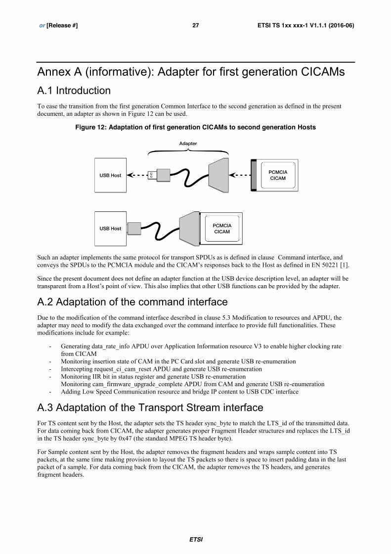
Annex A (informative): Adapter for first generation CICAMs A.1 Introduction To ease the transition from the first generation Common Interface to the second generation as defined in the present document, an adapter as shown in Figure 12 can be used.
Figure 12: Adaptation of first generation CICAMs to second generation Hosts
Such an adapter implements the same protocol for transport SPDUs as is defined in clause Command interface, and conveys the SPDUs to the PCMCIA module and the CICAM’s responses back to the Host as defined in EN 50221 [1].
Since the present document does not define an adapter function at the USB device description level, an adapter will be transparent from a Host’s point of view. This also implies that other USB functions can be provided by the adapter.
A.2 Adaptation of the command interface Due to the modification of the command interface described in clause 5.3 Modification to resources and APDU, the adapter may need to modify the data exchanged over the command interface to provide full functionalities. These modifications include for example:
- Generating data_rate_info APDU over Application Information resource V3 to enable higher clocking rate from CICAM
- Monitoring insertion state of CAM in the PC Card slot and generate USB re-enumeration - Intercepting request_ci_cam_reset APDU and generate USB re-enumeration - Monitoring IIR bit in status register and generate USB re-enumeration
Monitoring cam_firmware_upgrade_complete APDU from CAM and generate USB re-enumeration - Adding Low Speed Communication resource and bridge IP content to USB CDC interface
A.3 Adaptation of the Transport Stream interface For TS content sent by the Host, the adapter sets the TS header sync_byte to match the LTS_id of the transmitted data. For data coming back from CICAM, the adapter generates proper Fragment Header structures and replaces the LTS_id in the TS header sync_byte by 0x47 (the standard MPEG TS header byte).
For Sample content sent by the Host, the adapter removes the fragment headers and wraps sample content into TS packets, at the same time making provision to layout the TS packets so there is space to insert padding data in the last packet of a sample. For data coming back from the CICAM, the adapter removes the TS headers, and generates fragment headers.
ETSI
ETSI TS 1xx xxx-1 V1.1.1 (2016-06) 28 or [Release #]
Annex B (informative): Providing connectivity with a bridge B.1 Configuration
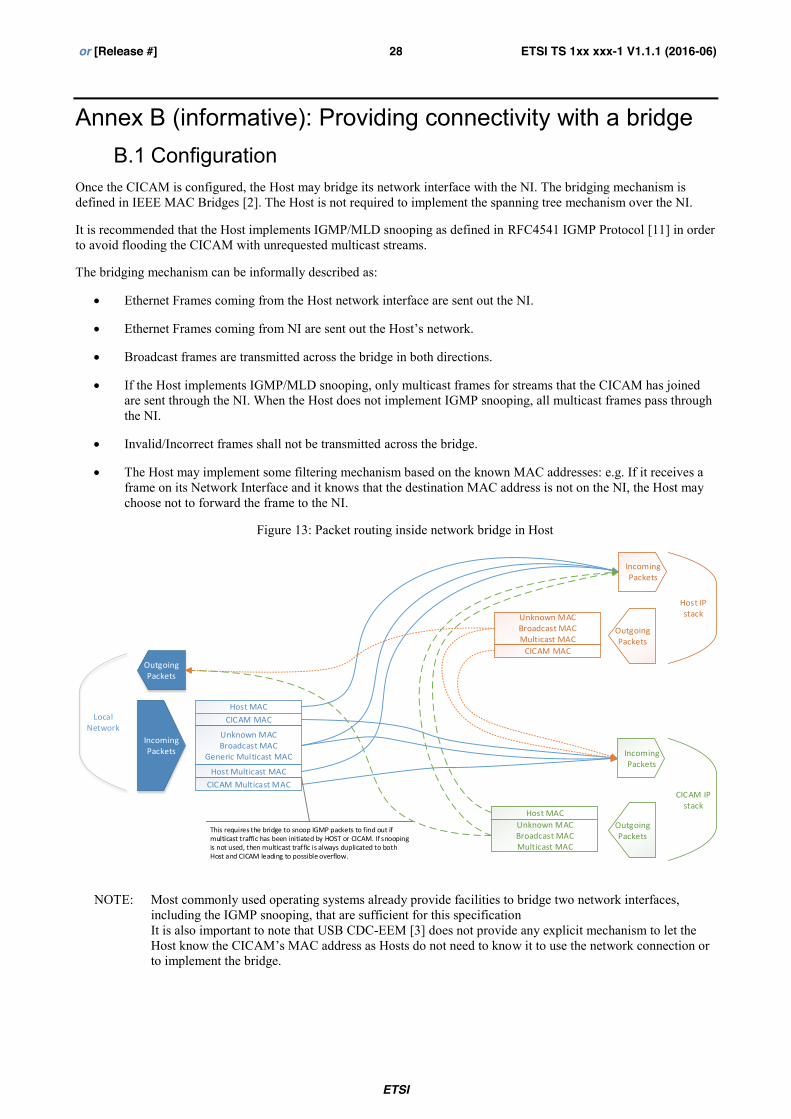
Once the CICAM is configured, the Host may bridge its network interface with the NI. The bridging mechanism is defined in IEEE MAC Bridges [2]. The Host is not required to implement the spanning tree mechanism over the NI.
It is recommended that the Host implements IGMP/MLD snooping as defined in RFC4541 IGMP Protocol [11] in order to avoid flooding the CICAM with unrequested multicast streams.
The bridging mechanism can be informally described as:
x Ethernet Frames coming from the Host network interface are sent out the NI.
x Ethernet Frames coming from NI are sent out the Host’s network.
x Broadcast frames are transmitted across the bridge in both directions.
x If the Host implements IGMP/MLD snooping, only multicast frames for streams that the CICAM has joined are sent through the NI. When the Host does not implement IGMP snooping, all multicast frames pass through the NI.
x Invalid/Incorrect frames shall not be transmitted across the bridge.
x The Host may implement some filtering mechanism based on the known MAC addresses: e.g. If it receives a frame on its Network Interface and it knows that the destination MAC address is not on the NI, the Host may choose not to forward the frame to the NI.
Figure 13: Packet routing inside network bridge in Host
Host MACCICAM MAC
Unknown MACBroadcast MAC
Generic Multicast MAC
Host Multicast MACCICAM Multicast MAC
CICAM MAC
Unknown MACBroadcast MACMulticast MAC
Host MAC
IncomingPackets
OutgoingPackets
LocalNetwork
CICAM IP stack
OutgoingPackets
OutgoingPackets
IncomingPackets
IncomingPackets
Host IP stack
Unknown MACBroadcast MACMulticast MAC
This requires the bridge to snoop IGMP packets to find out if multicast traffic has been initiated by HOST or CICAM. If snooping is not used, then multicast traffic is always duplicated to both Host and CICAM leading to possible overflow.
NOTE: Most commonly used operating systems already provide facilities to bridge two network interfaces, including the IGMP snooping, that are sufficient for this specification It is also important to note that USB CDC-EEM [3] does not provide any explicit mechanism to let the Host know the CICAM’s MAC address as Hosts do not need to know it to use the network connection or to implement the bridge.
ETSI
ETSI TS 1xx xxx-1 V1.1.1 (2016-06) 29 or [Release #]
B.2 IGMP snooping description The present clause presents a brief description of the behaviour of a Host implementing IGMP snooping when receiving a multicast-related frame.
MLD snooping, which is the equivalent of IGMP snooping for IPv6, follows the same principles according to RFC4541 IGMP Protocol [11].
The Host applies the following rules when processing IGMP packets:
x The Host keeps a list of the known multicast routers and the multicast streams that the CICAM has joined.
x The Host only sends IGMP Membership reports through the NI if the CICAM presents itself as a multicast router otherwise they are discarded
x The Host forwards all unrecognized IGMP messages through the NI.
x The Host does not forward IP or IGMP packets with incorrect CRC
x The Host has a timeout to cope with a potential absence of IGMP leave announcements
The Host applies the following rules when processing IP packets with a destination IP address in the multicast range:
x Packets with a multicast IP destination address outside 224.0.0.X are sent through the NI only if the CICAM has joined the multicast group or if the CICAM presents itself as a multicast router
x Packets with a multicast IP destination address in 224.0.0.X that are not IGMP are forwarded through the NI.
x Packets with an unknown multicast IP destination address are sent to the CICAM only if it presents itself as a multicast router
ETSI
ETSI TS 1xx xxx-1 V1.1.1 (2016-06) 30 or [Release #]


![Digital Video Broadcasting (DVB); Implementation …digitus.itk.ppke.hu/~takacsgy/a147_DVB-C2_Imp-Guide[1].pdfDigital Video Broadcasting (DVB); Implementation Guidelines for a second](https://static.documents.pub/doc/80x56/5fd9ac210e2d412ea673fdfd/digital-video-broadcasting-dvb-implementation-takacsgya147dvb-c2imp-guide1pdf.jpg)


