19
Operator’s Manual Digital Water Baths 110-288 06.17.11
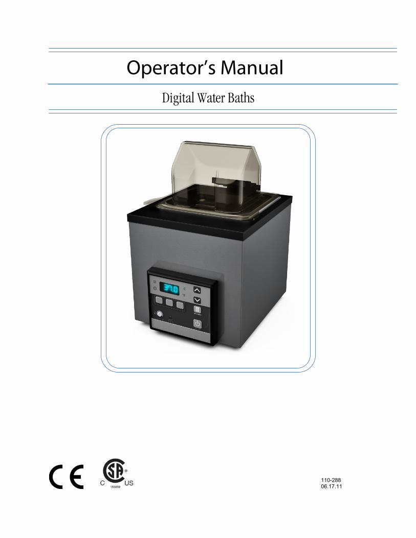
Operator’s Manual Digital Water Baths
110-288 06.17.11

110-288 1
Table of Contents Introduction .................................................................................................................................................2
General Safety Information .......................................................................................................................2 Safety Recommendations .........................................................................................................................3 Regulatory Compliance & Testing.............................................................................................................3 Unpacking Your Water Bath......................................................................................................................4 Contents ....................................................................................................................................................4 Controls .....................................................................................................................................................4
Installation and Startup ..............................................................................................................................5 General Site Requirements .......................................................................................................................5 Adding Liquid to the Reservoir ..................................................................................................................5 Attaching the Reservoir Cover ..................................................................................................................6 Electrical Power.........................................................................................................................................6 Controller Setup.........................................................................................................................................7
Safety Set Temperature.........................................................................................................................7 Normal Operation........................................................................................................................................8
Controls .....................................................................................................................................................8 Turning Your Water Bath ON ....................................................................................................................8 Viewing the Set Point Temperature...........................................................................................................8 Adjusting the Set Point Temperature ........................................................................................................8 Selecting the Temperature Unit.................................................................................................................9 Setting the High Limit Temperature...........................................................................................................9 Setting the Temperature Presets ..............................................................................................................9 Using the Temperature Presets ..............................................................................................................10 Enabling / Disabling the Local Lockout ...................................................................................................10 Setting the Calibration Offset ..................................................................................................................10 Restoring the Factory Default Settings....................................................................................................10
Display Messages .....................................................................................................................................11 Routine Maintenance & Troubleshooting...............................................................................................12
Cleaning the Bath ....................................................................................................................................12 Disassembling the Bath...........................................................................................................................12 Replacing Fuses......................................................................................................................................12 Troubleshooting Chart .............................................................................................................................13
Technical Information...............................................................................................................................14 Performance Specifications.....................................................................................................................14 Reservoir Fluids.......................................................................................................................................15 Application Notes.....................................................................................................................................16
Equipment Disposal (WEEE Directive) ...................................................................................................16 Replacement Parts....................................................................................................................................16 Bath Fluids.................................................................................................................................................17 Service and Technical Support ...............................................................................................................17 Warranty.....................................................................................................................................................18
110-288 2
Introduction Thank you for choosing this Water Bath. It is designed to handle a wide range of laboratory procedures, including: incubation, inactivation, and agglutination as well as most pharmaceutical, serological, biomedical, and industrial procedures.
To ensure optimum temperature uniformity, your Water Bath features an energy efficient, large-area heater and thermostatic control. Its PID microprocessor control (Proportional Integral Derivative) system provides proportional heat control by anticipating the approach to your set point temperature and preventing overshoot. A redundant safety thermostat is standard on all models.
General Safety Information When installed, operated, and maintained according to the directions in this manual and common safety procedures, your Water Bath should provide safe and reliable temperature control. Please ensure that all individuals involved in the installation, operation, or maintenance of this Water Bath read this manual thoroughly prior to working with the unit.
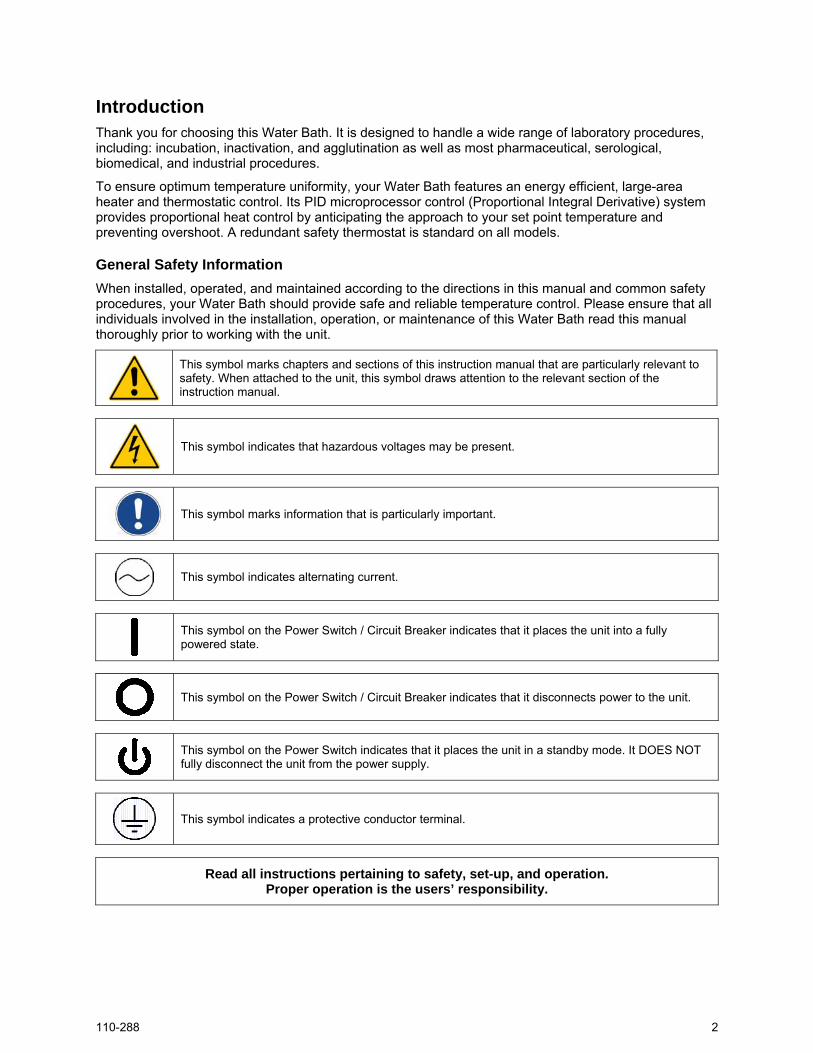
This symbol marks chapters and sections of this instruction manual that are particularly relevant to safety. When attached to the unit, this symbol draws attention to the relevant section of the instruction manual.
This symbol indicates that hazardous voltages may be present.
This symbol marks information that is particularly important.
This symbol indicates alternating current.
This symbol on the Power Switch / Circuit Breaker indicates that it places the unit into a fully powered state.
This symbol on the Power Switch / Circuit Breaker indicates that it disconnects power to the unit.
This symbol on the Power Switch indicates that it places the unit in a standby mode. It DOES NOT fully disconnect the unit from the power supply.
This symbol indicates a protective conductor terminal.
Read all instructions pertaining to safety, set-up, and operation. Proper operation is the users’ responsibility.

110-288 3
Safety Recommendations To prevent injury to personnel and/or damage to property, always follow your workplace’s safety procedures when operating this equipment. You should also comply with the following safety recommendations:
WARNING:
• Always connect the power cord on this Water Bath to a grounded (3-prong) power outlet. Make certain that the outlet is the same voltage and frequency as your unit.
• Never operate the Water Bath with a damaged power cord.
• Always turn the Water Bath OFF and disconnect mains power before performing any maintenance or service.
WARNING:
• Never operate the Water Bath without bath fluid in the reservoir. Periodically check the reservoir to ensure that the liquid depth is within acceptable levels. Always refill the reservoir using the same bath fluid type that is already in the reservoir. Bath oil must not contain any water contaminants and should be preheated to the actual bath temperature before adding as there is an explosion hazard at high temperatures.
• Use compatible bath fluids only.
• Always drain all fluid from the reservoir before moving or lifting your Water Bath. Be sure to follow your organization’s procedures and practices regarding the safe lifting and relocation of heavy objects.
WARNING: Always allow the bath fluid to cool to ambient temperature before draining.
WARNING: It is the user’s responsibility to properly decontaminate the unit in the event hazardous materials are spilled on exterior or interior surfaces. Consult manufacturer if there is any doubt regarding the compatibility of decontamination or cleaning agents.
Regulatory Compliance & Testing
CSA (60 Hz units) CAN/CSA C22.2 No. 0-M91 — General Requirement Canadian Electrical Code, Part II CAN/CSA C22.2 No. 1010.1-92 — Safety Requirements for Electrical Equipment for Measurement, Control, and Laboratory Use; Part I: General Requirements UL Std. No. 61010A-1 — Electrical Equipment for Laboratory Use, Part I: General Requirements IEC 61010-1 — Safety Requirements for Electrical Equipment for Measurement, Control, and Laboratory Use; Part I: General Requirements
CE (50 Hz units) EC Low Voltage Directive 2006/95/EC EC Electromagnetic Compatibility Directive 2004/108/EC IEC 61010-1-2001 IEC 61010-2-2001 IEC 61326:2005 / EN 61326 : 2006

110-288 4
Unpacking Your Water Bath
Your water bath is shipped in a special carton. Retain the carton and all packing materials until the unit is completely assembled and working properly. Set up and run the unit immediately to confirm proper operation. Beyond one week, your unit may be warranty repaired, but not replaced. If the unit is damaged or does not operate properly, contact the transportation company, file a damage claim, then contact the company where your unit was purchased.
WARNING: Keep unit upright when moving. Be sure to follow your company’s procedures and practices regarding the safe lifting and relocation of heavy objects.
Contents The items included with your Water Bath are:
• Water Bath • Gabled Reservoir Cover Assembly • Sample Tray • Operator’s Manual • Power Cord
Controls
Heat Indicator Lit when heater is active.
Digital Display Displays temperature and options.
Not used.
Temperature Preset Buttons – P1, P2, P3 Used to quickly select user-defined set point
temperatures. Also used to set operational
features.
Safety Thermostat Used to adjust safety set
point temperature.
Over Temperature Safety Indicator Lights when bath temperature exceeds
safety set point temperature.
Power Button Turns power to the Controller ON and OFF.
Set/Menu Button Press to allow set point changes and switch digital display between set point and actual temperatures. Also used to enable/disable local lockout.
Selection Buttons Used to increase or decrease temperature settings and option values.
Temperature Units Indicators Lit to indicates unit of measure in which temperature is being displayed. User-selectable.

110-288 5
Installation and Startup Your Water Bath is designed to be simple to setup and install. The only tools required are a flat-head screwdriver and a container for adding water or another suitable fluid to the bath reservoir.
General Site Requirements Locate your Water Bath on a level surface in an area that is free from drafts and wide ambient temperature variations, such as near heater or air conditioning vents. Do not place it where there are corrosive fumes, excessive moisture, or in excessively dusty areas.
Avoid voltage drops by using properly grounded power outlets wired with 14 gauge or larger diameter wire and, if possible, be close to the power distribution panel. The use of extension cords is not recommended; this will reduce the potential for problems caused by low line voltage.
Adding Liquid to the Bath Reservoir
WARNING: Read the safety data sheet for the bath fluid being used carefully before filling reservoir.
WARNING: See Technical Information in the rear of this manual for a list of compatible liquids.
WARNING: If the proper fluid level is not maintained, the unit could possibly be damaged (fluid level too low) or the bath may overflow (fluid level too high).
CAUTION: Fumes from acidic solutions may cause corrosion of the stainless steel reservoir. Care should be taken to maintain a neutral pH at all times.
Fill bath so that liquid level is approximately one inch (2.54 cm) from top when samples are placed in bath.
To ensure accurate reading of temperature, the fluid level should not be less than 2 inches (5.08 cm) from the bottom of the unit. Operation of the bath without fluid will not damage the heater, but will cause permanent discoloration of the tank and will not provide accurate temperature information.
Distilled water is preferred for temperatures from 10° to 90°C (50° to 194°F). A variety of fluids can be used with the bath depending on the application. The fluid must be compatible with 300 series stainless steel. See Technical Information, Reservoir Fluids in the rear of this manual for a list of compatible fluids.
If using water, a few drops of polyclean Algaecide (part number 004-300040) should be used to help prevent algae formation.
WARNING: Always drain all fluid from the reservoir before moving or lifting your Water Bath. Be sure to follow your organization’s procedures and practices regarding the safe lifting and relocation of heavy objects.
WARNING: To avoid the potential for burns, allow the Water Bath to cool completely before cleaning or performing any maintenance.

110-288 6
Attaching the Reservoir Cover Your water bath comes fully assembled. To achieve stable operating temperatures above 60ºC/140ºF, use of the included reservoir cover is required. To attach the reservoir cover, insert the hinge into the bracket on the rear of the bath housing.
When properly installed, the lid tilts up to a 90º position, allowing condensate to drain back into the bath.
Electrical Power
WARNING: The Water Bath’s power cord must be connected to a properly grounded electrical receptacle. Make certain that this electrical outlet is the same voltage and frequency as your Water Bath. The correct voltage and frequency for your Water Bath are indicated on the identification label on the rear of the unit.
CAUTION: The use of an extension cord is not recommended. If one is necessary, it must be properly grounded and capable of handling the total wattage of the unit. The extension cord must not cause more than a 10% drop in voltage to the unit.
Insert female end of included IEC line cord into the IEC electrical outlet on rear of the water bath. Insert the male end of the line cord into a properly grounded wall outlet.
Once the unit is plugged in, will be displayed on the controller, indicating the unit is in stand-by mode. The unit will stay in stand-by mode until powered ON by pressing the Power Button on the front control panel.
Insert reservoir cover hinge into bracket on rear
of bath housing.
IEC electrical connection
Fuse cover

110-288 7
Controller Setup
Safety Set Temperature
This is a “Do Not Exceed” temperature setting for your Water Bath and is the temperature at which the heater will be turned OFF should the liquid level in the bath drop too low or the Water Bath malfunctions. It is normally set about 5° higher than the desired operating temperature. The Safety Set temperature is adjusted as follows:
1. Using a flat blade screwdriver, rotate the Safety Thermostat clockwise until it stops.
2. Turn power to the controller ON by pressing the Power Button.
3. Press the Set/Menu Button. Set point will be displayed and the decimal point will flash.
4. Press the Selection Buttons to adjust the set point temperature to the desired safety set temperature and press the Set/Menu Button to accept the new temperature value.
5. Once the bath temperature has stabilized at the desired value, slowly rotate the Safety Thermostat counter-clockwise until the Safety Indicator light turns ON.
6. Slowly rotate the Safety Thermostat clockwise until the Safety Indicator light turns OFF.
Your bath is now ready for operation.
WARNING: The Safety Thermostat is user-adjustable. Do not force the control dial beyond the stops at either end of the dial’s range.
NOTE: If the Safety Set is activated during normal operation, the Safety Indicator light will turn ON and FT3 will appear on the digital display.

110-288 8
Normal Operation Controls
Power
Turns the Controller ON and OFF.
Set / Menu
Allows changes to temperature set point.
Switches temperature readout between actual and set point temperature.
Used to enable/disable the Local Lockout.
Selection
Used to increase/decrease temperature set point and other operational settings/values.
Temperature Presets
(P1, P2, P3)
Used to quickly select one of three user-defined set point temperatures.
Used in combination to set operational features.
Turning Your Water Bath ON
Press the key.
The firmware version and the set point temperature will appear briefly on the display. After 10 seconds, the actual bath temperature will be displayed. If the actual bath temperature is lower than the set point temperature, the heating symbol will also light.
Viewing the Set Point Temperature
Pressing at any time during normal operation toggles between the set point temperature and actual bath temperature displays.
Adjusting the Set Point Temperature This is the temperature at which the fluid in your bath will be maintained. It may be set to one-tenth of a degree. The factory default set point is +20.0°C / +68.0°F.
To Access: Press . The current set point temperature will be displayed and the decimal point will flash.
To Change: Press the and/or .
To Accept: Press or allow the digital display to return to the main temperature display (approximately 10 seconds).

110-288 9
Selecting the Temperature Unit
CAUTION: Changing the unit in which temperature is displayed also restores the factory default values for the temperature set point, temperature presets, and high limit. If a calibration value has been entered, this setting will be retained. The default temperature unit is °C.
To select °F:
Disconnect the electrical power cord at the rear of unit.
Press and hold while reconnecting the electrical power cord. dEF will be displayed and the unit will be set to operate in °F.
To select °C:
Disconnect the electrical power cord at the rear of unit.
Press and hold while reconnecting the electrical power cord. dEC will be displayed and the unit will be set to operate in °C.
Setting the High Limit Temperature This allows you to limit how high the temperature set point may be set. It also serves as a high limit safety, alerting you if bath temperature rises above the high limit temperature setting. The high limit can be set between 0° and 100°C / 32° and 212°F.
To Access: Press and simultaneously until100 is displayed on the digital readout.
To Change: Press the and/or keys.
To Accept: Press or allow the digital display to return to the main temperature display (approximately 10 seconds).
Setting the Temperature Presets The Temperature Preset Buttons enable you to set and select frequently used temperature set points. The temperature presets are set as follows:
To Access: Press the desired Preset Button — P1, P2, or P3. The LED associated with the selected button will begin to flash.
To Change: Use the and/or keys to adjust the displayed set point temperature to the desired value.
To Accept: Press the selected Preset Button a second time to accept the new set point.
IMPORTANT: The new set point temperature will not be saved unless the Preset Button is pressed this second time.
NOTE: Your Water Bath was supplied with two removable stick-on strips that can be applied below the Preset Buttons. You can write the set point temperature associated with each Preset Button directly on this strip. We recommend that you use an erasable medium, such as a dry erase marker or felt tip pen. The former can be wiped off with a dry cloth or tissue; the later can usually be removed with a cloth or tissue moistened with glass cleaner. Do not use a permanent marker or ballpoint pen. Always do an ink test before writing on these strips.
110-288 10
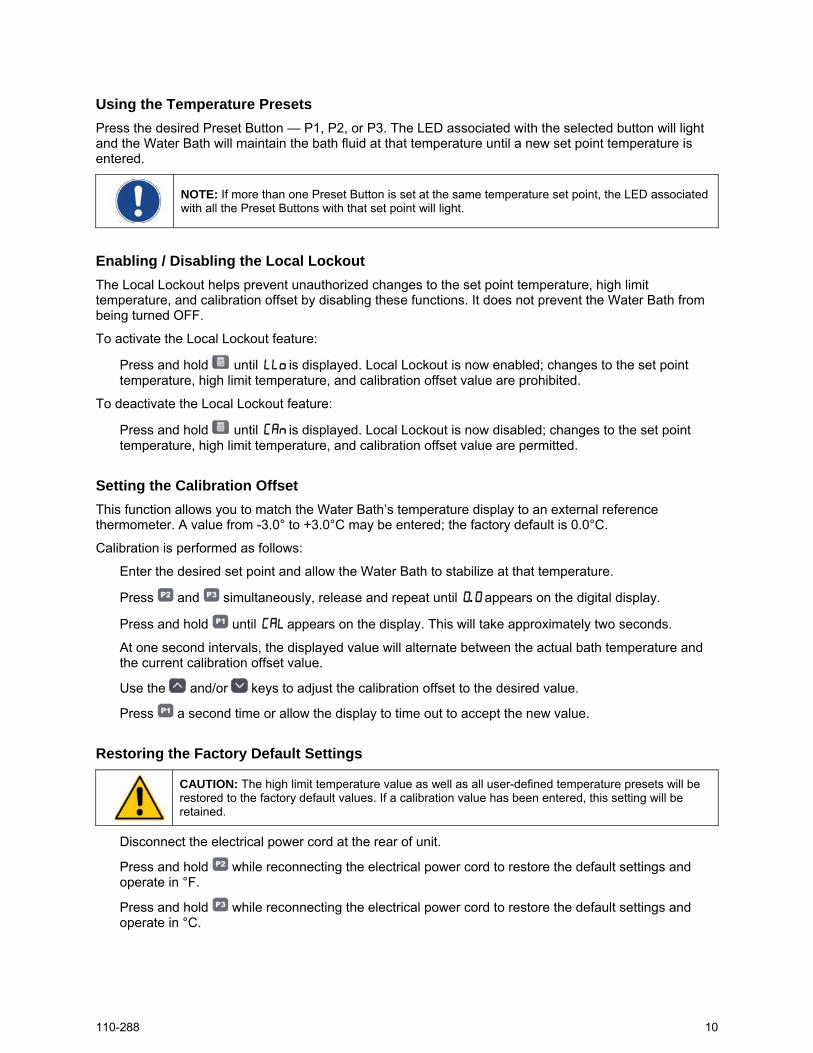
Using the Temperature Presets Press the desired Preset Button — P1, P2, or P3. The LED associated with the selected button will light and the Water Bath will maintain the bath fluid at that temperature until a new set point temperature is entered.
NOTE: If more than one Preset Button is set at the same temperature set point, the LED associated with all the Preset Buttons with that set point will light.
Enabling / Disabling the Local Lockout The Local Lockout helps prevent unauthorized changes to the set point temperature, high limit temperature, and calibration offset by disabling these functions. It does not prevent the Water Bath from being turned OFF.
To activate the Local Lockout feature:
Press and hold until LLo is displayed. Local Lockout is now enabled; changes to the set point temperature, high limit temperature, and calibration offset value are prohibited.
To deactivate the Local Lockout feature:
Press and hold until CAn is displayed. Local Lockout is now disabled; changes to the set point temperature, high limit temperature, and calibration offset value are permitted.
Setting the Calibration Offset This function allows you to match the Water Bath’s temperature display to an external reference thermometer. A value from -3.0° to +3.0°C may be entered; the factory default is 0.0°C.
Calibration is performed as follows:
Enter the desired set point and allow the Water Bath to stabilize at that temperature.
Press and simultaneously, release and repeat until 0.0 appears on the digital display.
Press and hold until CAL appears on the display. This will take approximately two seconds.
At one second intervals, the displayed value will alternate between the actual bath temperature and the current calibration offset value.
Use the and/or keys to adjust the calibration offset to the desired value.
Press a second time or allow the display to time out to accept the new value.
Restoring the Factory Default Settings
CAUTION: The high limit temperature value as well as all user-defined temperature presets will be restored to the factory default values. If a calibration value has been entered, this setting will be retained.
Disconnect the electrical power cord at the rear of unit.
Press and hold while reconnecting the electrical power cord to restore the default settings and operate in °F.
Press and hold while reconnecting the electrical power cord to restore the default settings and operate in °C.

110-288 11
Display Messages Display Description Action Required
. . Standby mode Normal — Indicates that the unit is plugged in and the Power Switch is OFF.
tx.xx Power up self-test Normal — Appears momentarily at startup, indicates software code version.
0 Calibration offset value Normal — Current calibration offset value.
Cal Calibration Mode Normal — Indicates unit is in Calibration mode.
h00 High Limit value Normal — Current High Limit value.
LLo Local Lockout Enabled Normal — Indicates Local Lockout has been enabled.
Can Local Lockout Disabled Normal — Indicates Local Lockout has been disabled.
eh1 High Limit set point too low Error — The High Limit value entered is below the temperature set point. Lower set point or increase high limit value.
ft1 High Limit value exceeded Error — Indicates bath temperature has exceeded the High Limit value. Increase High Limit value or lower set point.
ft2 EEPROM reset Error — Default unit to factory settings. If error persists, contact supplier.
ft3 Safety Set temperature exceeded Error — Bath temperature has exceeded the Safety set point. Lower temperature set point or increase Safety set point.
ft4 Heating Triac failure Error — Service required, contact supplier.
ft5 Temperature probe failure Error — Service required, contact supplier.
ft6 Communication error Error — Service required, contact supplier.
0.0 Internal fault Error — Service required, contact supplier.
p0x Factory setting Normal — Factory setting.
a0x Factory setting Normal — Factory setting.
.x.x Factory Calibration Offset Normal — Indicates calibration offset set by factory.

110-288 12
Routine Maintenance & Troubleshooting
WARNING: Hazardous voltages may be present. Disconnect power before performing maintenance.
Cleaning the Bath Thoroughly clean the bath before each use. Use only mild soap and water when cleaning. Do not use steel wool as damage to the unit may result. Non-steel scouring pads are acceptable. The entire unit is housed in a tough, well-insulated stainless steel casing that is corrosion and chemical resistant.
Disassembling the Bath The following procedure should only be performed by a qualified service technician. 1. Unplug the bath from its power source. 2. Drain the bath of all fluid; remove the cover and sample tray. 3. Turn the bath upside down to expose the bottom. Remove the screws around the outer edge of the
tank bottom plate. 4. Slide the bottom plate toward the front of the unit and lift off. 5. At this point, all the internal components are accessible for replacement.
Replacing Fuses To check / replace fuses: 1. Unplug the power cord from the rear of the unit. 2. Locate and remove the fuse cover located on the top of the
IEC power receptacle on the rear of the unit. 3. Check and replace fuses as needed; replace cover.

110-288 13
Troubleshooting Chart
Problem Cause Corrective Action No display No power to unit
Blown or loose fuse
Controller turned OFF
Check that power cord is connected to the bath and is plugged into an operating electrical outlet.
Check that fuse is in place and intact.
Turn Controller ON
No heating Set point lower than bath temperature
Bath temperature above Safety Set temperature
Bath temperature above High Limit temperature
Liquid level in bath is too low
Check set point temperature; increase as required.
Check if Safety Set indicator light is lit; adjust Safety Set temperature as required.
Verify that High Limit temperature is higher than current set point temperature; adjust as required.
Check that liquid level is at least 2 inches (5.08 cm) above bottom of tank; add fluid as required.
Insufficient heating Improper line voltage
Recent change in set point or heat load
Bath cover not in place
Check that line voltage meets specifications.
Allow sufficient time for bath temperature to stabilize when changes in heat load or set point are made.
Check that bath cover is in place.
Inaccurate bath temperature
Incorrect calibration Calibrate bath as required.

110-288 14
Technical Information Performance Specifications Working Temperature: Ambient +5° to 100°C (ambient +10° to 212°F)
60°C (140°F) without cover
Temperature Uniformity: ±0.2°C @ 37°C (±0.4°F @ 98.6°F)
Temperature Stability: ±0.25°C (±0.5°F)
Electrical Requirements Reservoir Size Reservoir Dimensions
(L x W x D) Heater
Wattage 120 V, 60 Hz 240 V, 50 Hz
2 liter 3.9 x 4.3 x 5.5” 9.9 x 10.9 x 14 cm 300 2.5 A 1.25 A
2 liter shallow 5 x 10.8 x 1.9” 12.7 x 27.4 x 4.8 cm 300 2.5 A 1.25 A
5 liter 5 x 10.8 x 5.5” 12.7 x 27.4 x 14 cm 500 4.2 A 2.1 A
10 liter 10.6 x 11.6 x 5.5” 26.9 x 29.5 x 14 cm 500 4.2 A 2.1 A
20 liter 9.5 x 17.5 x 5” 24.1 x 44.5 x 12.7 cm 1000 8.3 A 4.15 A
28 liter 9.5 x 17.5 x 7” 24.1 x 44.5 x 17.8 cm 1000 8.3 A 4.15 A
Environmental Conditions Indoor use only Maximum Altitude: 2000 meter Operating Ambient: 5° to 35°C (41° to 95°F) Relative Humidity: 80%, non-condensing Installation Category: II Pollution Degree: 2

110-288 15
Reservoir Fluids
WARNING: Do not operate unit with any potentially flammable materials, as a fire hazard may result.
Specific Heat
Fluid Description @ Fluid Temperature BTU/lb°F KJ/Kg°C
Normal Temperature
Range
Extreme Temperature
Range
distilled water 50°C 1.00 4.18 10° to 90°C 2° to 100°C
polyclear MIX 30 50°C 1.00 4.18 15° to 90°C 2° to 100°C
polycool HC -50 -30°C 0.62 2.59 -50° to 100°C -62° to 118°C
polycool EG -25 (50/50 mix with distilled H2O) -20°C 0.78 3.26 -25° to 100°C -30° to 115°C
polycool EG -25 (30/70 mix with distilled H2O) 0°C 0.89 3.72 0° to 95°C -15° to 107°C
polycool PG -20 (50/50 mix with distilled H2O) -10°C 0.83 3.47 -20° to 100°C -30° to 115°C
polycool PG -20 (30/70 mix with distilled H2O) 5°C 0.92 3.85 5° to 90°C -10° to 107°C
polycool MIX -25 (50/50 mix with distilled H2O) -20°C 0.78 3.26 -25° to 100°C -30° to 115°C
polycool MIX -25 (30/70 mix with distilled H2O) 0°C 0.89 3.72 0° to 95°C -15° to 107°C
WARNING: DO NOT USE THE FOLLOWING LIQUIDS • Automotive antifreeze with additives**
• Hard tap water**
• Deionized water with a specific resistance > 1 meg ohm
• Any flammable fluids
• Concentrations of acids or bases
• Solutions with halides: chlorides, fluorides, bromides, iodides or sulfur
• Bleach (Sodium Hypochlorite)
• Solutions with chromates or chromium salts
• Glycerine
• Syltherm fluids
** At temperatures above 40°C, additives or mineral deposits may develop. If deposits are allowed to build up, the unit may overheat and fail. Higher temperatures and higher concentrations of additives will hasten deposit build up.
CAUTION: Fumes from acidic solutions may cause corrosion of the stainless steel reservoir. Care should be taken to maintain a neutral pH at all times.
Stay within the fluid’s normal range for best temperature stability and low vaporization. At fluid’s high temperature extreme:
• A fume hood may be required to prevent the buildup of vapors inside the room.
• Fluid lost from vapor will have to be frequently replenished.
• Caution must be taken to stay well below the fluid’s flashpoint.
110-288 16
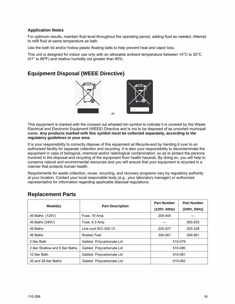
Application Notes For optimum results, maintain fluid level throughout the operating period, adding fluid as needed. Attempt to refill fluid at same temperature as bath.
Use the bath lid and/or hollow plastic floating balls to help prevent heat and vapor loss.
This unit is designed for indoor use only with an allowable ambient temperature between +5°C to 30°C (41° to 86ºF) and relative humidity not greater than 80%.
Equipment Disposal (WEEE Directive)
or
This equipment is marked with the crossed out wheeled bin symbol to indicate it is covered by the Waste Electrical and Electronic Equipment (WEEE) Directive and is not to be disposed of as unsorted municipal waste. Any products marked with this symbol must be collected separately, according to the regulatory guidelines in your area.
It is your responsibility to correctly dispose of this equipment at lifecycle-end by handing it over to an authorized facility for separate collection and recycling. It is also your responsibility to decontaminate the equipment in case of biological, chemical and/or radiological contamination, so as to protect the persons involved in the disposal and recycling of the equipment from health hazards. By doing so, you will help to conserve natural and environmental resources and you will ensure that your equipment is recycled in a manner that protects human health.
Requirements for waste collection, reuse, recycling, and recovery programs vary by regulatory authority at your location. Contact your local responsible body (e.g., your laboratory manager) or authorized representative for information regarding applicable disposal regulations.
Replacement Parts
Model(s) Part Description Part Number
(120V, 60Hz)
Part Number
(240V, 50Hz)
All Baths (120V) Fuse, 10 Amp 200-455 ---
All Baths (240V) Fuse, 6.3 Amp --- 200-253
All Baths Line cord IEC-320-13 225-227 225-228
All Baths Rubber Feet 300-561 300-561
2 liter Bath Gabled Polycarbonate Lid 510-079
2 liter Shallow and 5 liter Baths Gabled Polycarbonate Lid 510-080
10 liter Bath Gabled Polycarbonate Lid 510-081
20 and 28 liter Baths Gabled Polycarbonate Lid 510-082

110-288 17
Bath Fluids
Circulating Bath Fluids Quantity Part Number
polyclean Algaecide 8 oz / 236 ml 004-300040
polyclean Algaecide Twelve 8 oz / 236 ml bottles 004-300041
polyclean Bath Cleaner 8 oz / 236 ml 004-300050
polyclean Bath Cleaner Twelve 8 oz / 236 ml bottles 004-300051
polycool EG -25 (ethylene glycol) 1 gal / 4.5 liter 060340
polycool PG -20 (propylene glycol) 1 gal / 4.5 liter 060320
polycool HC -50 (water-based heat transfer fluid) 1 gal / 4.5 liter 060330
polycool MIX -25 (50/50 blend polycool EG -25 / H2O plus polyclean algaecide)
Five 0.5 gal / 2.27 liter 004-300060
polyclear MIX 30 (distilled water plus polyclean algaecide)
Five 0.5 gal / 2.27 liter 004-300062
Service and Technical Support If you have followed the troubleshooting steps outlined previously and your Water Bath still fails to operate properly, contact the supplier from whom the unit was purchased. Have the following information available for the customer service person:
• Model, Serial Number, and Voltage (from back panel label)
• Date of purchase and purchase order number
• Supplier’s order number or invoice number
• A summary of the problem
110-288 18
Warranty The manufacturer agrees to correct for the original user of the product, either by repair (using new or refurbished parts), or at the manufacturer’s election, by replacement (with a new or refurbished product), any defects in material or workmanship which develop during the warranty period. The standard warranty is twenty-four (24) months after delivery of the product. In the event of replacement, the replacement unit will be warranted for the remainder of the original warranty period or ninety (90) days, whichever is longer. For purposes of this limited warranty, “refurbished” means a product or part that has been returned to its original specifications. In the event of a defect, these are your exclusive remedies.
If the product should require service, contact the manufacturer’s/supplier’s office for instructions. When return of the product is necessary, a return authorization number is assigned and the product should be shipped, transportation charges pre-paid, in either its original packaging or packaging affording an equal degree of protection to the indicated service center. To insure prompt handling, the return authorization number must be placed on the outside of the package. A detailed explanation of the defect should be enclosed with the item.
The warranty shall not apply if the defect or malfunction was caused by accident, neglect, unreasonable use, improper service, acts of God, modification by any party other than the manufacturer, or other causes not arising out of defects in material or workmanship.
EXCLUSION OF IMPLIED WARRANTIES. THERE ARE NO WARRANTIES, EXPRESSED OR IMPLIED, INCLUDING, BUT NOT LIMITED TO, THOSE OF MERCHANTABILITY OR FITNESS FOR A PARTICULAR PURPOSE WHICH EXTEND BEYOND THE DESCRIPTION AND PERIOD AS STATED IN THE OPERATOR’S MANUAL INCLUDED WITH EACH PRODUCT.
LIMITATION ON DAMAGES. THE MANUFACTURER’S SOLE OBLIGATION UNDER THE WARRANTY IS LIMITED TO THE REPAIR OR REPLACEMENT OF A DEFECTIVE PRODUCT AND THE MANUFACTURER SHALL NOT, IN ANY EVENT, BE LIABLE FOR ANY INCIDENTAL OR CONSEQUENTIAL DAMAGES OF ANY KIND RESULTING FROM USE OR POSSESSION OF THIS PRODUCT.
Some states do not allow: (A) limitations on how long an implied warranty lasts; or (B) the exclusion or limitation of incidental or consequential damages, so the above limitations or exclusions may not apply to you. This warranty gives you specific legal rights and you may have other rights that vary from state to state.
Manufactured by:
PolyScience 6600 W. Touhy Avenue Niles, IL 60714 U.S.A.
1-800-229-7569 ● 1-847-647-0611 www.polyscience.com


