114
8530 DigiTOL® INDICATOR Technical Manual A13012500A 12/95
8530DigiTOL®INDICATOR
TechnicalManual
A13012500A12/95

INTRODUCTION
This publication is provided solely as a guide for individuals who have received TechnicalTraining in servicing the METTLER TOLEDO product.
Information regarding METTLER TOLEDO Technical Training may be obtained by writing to: METTLER TOLEDO Training Center P.O. Box 1705 Columbus, Ohio 43216 (614) 438-4400
FCC NOTE
NOTE: This equipment has been tested and found to comply with the limits of the UnitedStates of America FCC rules for a Class A digital device, pursuant to Part 15 of the FCC Rulesand the Radio Interference Regulations of the Canadian Department of Communications. These limits are designed to provide reasonable protection against harmful interference whenthe equipment is operated in a commercial environment. This equipment generates, uses, andcan radiate radio frequency energy and, if not installed and used in accordance with theinstruction manual, may cause harmful interference to radio communications. Operation ofthis equipment in a residential area is likely to cause harmful interference in which case theuser will be required to correct the interference at his own expense.
This manual describes the installation and operation of the Model 8530 DigiTOL® Indicatorwith software part number [128831] and software revision level [L09]. The software partnumber and revision level are the second and third prompts displayed at power up.
If the software part number displayed at power up is [134621] then the 8530 contains theVehicle Scale software version which this manual does not cover. Refer to the 8530 VehicleScale Technical manual TMVS8530 I00 for installation and operating instructions for thisversion of software.
If the software revision level displayed at power up is [L08] or lower then this technical manualwill describe several features which your unit does not provide. A software upgrade KOP, partnumber M128510 00A can be ordered and installed in the 8530 if the features of the latestversion are required.
IMPORTANT!It is most important that the correct part number is used when ordering parts. Parts orders aremachine processed, using only the part number and quantity as shown on the order. Ordersare not edited to determine if the part number and description agree.
METTLER TOLEDO RESERVES THE RIGHT TO MAKE REFINEMENTS OR CHANGES WITHOUT NOTICE.

PRECAUTIONS
WARNINGONLY PERMIT QUALIFIED PERSONNEL TO SERVICETHIS EQUIPMENT. EXERCISE CARE WHEN MAKINGCHECKS, TESTS AND ADJUSTMENTS THAT MUST BEMADE WITH POWER ON. FAILING TO OBSERVETHESE PRECAUTIONS CAN RESULT IN BODILYHARM.
WARNINGFOR CONTINUED PROTECTION AGAINST SHOCKHAZARD CONNECT TO PROPERLY GROUNDEDOUTLET ONLY.DO NOT REMOVE THE GROUND PRONG.
WARNINGDISCONNECT ALL POWER TO THIS UNIT BEFOREREMOVING THE FUSE OR SERVICING.
CAUTIONBEFORE CONNECTING/DISCONNECTING ANY INTERNALELECTRONIC COMPONENTS OR INTERCONNECTING WIRINGBETWEEN ELECTRONIC EQUIPMENT, ALWAYS REMOVE POWER ANDWAIT AT LEAST THIRTY (30) SECONDS BEFORE ANY CONNECTIONSOR DISCONNECTIONS ARE MADE. FAILURE TO OBSERVE THESEPRECAUTIONS COULD RESULT IN DAMAGE TO, OR DESTRUCTIONOF THE EQUIPMENT OR BODILY HARM.
CAUTIONOBSERVE PRECAUTIONS FOR HANDLING ELECTROSTATIC SENSITIVEDEVICES.
READ this manualBEFORE operating orservicing thisequipment.
FOLLOW theseinstructions carefully.
SAVE this manual forfuture reference.
DO NOT allowuntrained personnel tooperate, clean, inspect,maintain, service, ortamper with thisequipment.
ALWAYSDISCONNECT thisequipment from thepower source beforecleaning or performingmaintenance.

CONTENTS
1. GENERAL DESCRIPTION ................................................................................. 1-11.1 STANDARD FEATURES .......................................................................................1-11.2 OPTIONAL FEATURES.........................................................................................1-2
2. SYSTEM DESCRIPTION................................................................................... 2-12.1 8530 MAJOR COMPONENTS...............................................................................2-12.2 DIGITOL® POWER CELL VEHICLE SCALE SYSTEM DESCRIPTION ...............2-1
2.2.1 Power Cell ......................................................................................................................................2-12.2.2 Pit Power Supply (NMOS Power Cells Only)...............................................................................2-12.2.3 Auxiliary Power Supply .................................................................................................................2-2
2.3 SINGLE DIGITOL LOAD CELL BASE DESCRIPTION..........................................2-22.4 MODEL 2160 DIGITOL® FLOOR SCALE AND DIGITAL J-BOX DESCRIPTION.2-22.5 MODEL 8530 FACTORY NUMBER REFERENCE................................................2-2
3. SPECIFICATIONS ........................................................................................... 3-13.1 ENVIRONMENT.....................................................................................................3-13.2 HAZARDOUS AREAS ...........................................................................................3-13.3 STANDARDS COMPLIANCE ................................................................................3-13.4 POWER REQUIREMENTS....................................................................................3-23.5 RADIO FREQUENCY INTERFERENCE ...............................................................3-23.6 APPEARANCE AND DIMENSIONS.......................................................................3-23.7 JN PRINTER PORT...............................................................................................3-4
3.7.1 Continuous Output.........................................................................................................................3-43.7.2 Demand Mode Output....................................................................................................................3-43.7.3 Remote ASCII Control Input .........................................................................................................3-4
3.8 OPTIONAL JW HOST PORT.................................................................................3-4
4. INSTALLATION INSTRUCTIONS........................................................................ 4-14.1 UNPACKING..........................................................................................................4-14.2 OPENING THE ENCLOSURE ...............................................................................4-1
4.2.1 Opening the Desk Enclosure..........................................................................................................4-14.2.2 Opening the Wall Enclosure...........................................................................................................4-14.2.3 Opening the Rack Enclosure..........................................................................................................4-1
4.3 SELECT DigiTOL® LOAD CELL INTERFACE ......................................................4-24.3.1 Install the Single DLC Harness, (If Required)...............................................................................4-24.3.2 Install the Multiple DLC Harness, (If Required)...........................................................................4-2
4.4 AC POWER VOLTAGE SELECTION, EXPORT VERSIONS ONLY .....................4-44.4.1 Desk and Rack Enclosure Versions AC Line Voltage Selection....................................................4-44.4.2 Wall Enclosure Version AC Line Voltage Selection ......................................................................4-4
4.5 MAIN PCB PREPARATIONS.................................................................................4-54.6 TERMINATE EXTERNAL WIRING........................................................................4-6
4.6.1 Terminate Vehicle Scale Home Run Cable (If Used).....................................................................4-64.6.2 Terminate Single DigiTOL® Load Cell Cable (If Used) ..............................................................4-64.6.3 Terminate JN Printer Port Interface Cable.....................................................................................4-64.6.4 Terminate JW Host Port Interface Cable .......................................................................................4-6

4.7 NEW SCALE INSTALLATION NOTES..................................................................4-74.7.1 DigiTOL® Vehicle Scale Installation Notes ..................................................................................4-74.7.2 Single DLC, Model 2157, Model 2160/Digital J-box Installation Notes .....................................4-8
4.8 PROGRAMMING AND CALIBRATION................................................................4-104.8.1 Keyboard Functions During Setup...............................................................................................4-104.8.2 Access the Setup Mode ................................................................................................................4-104.8.3 Model 8530 Setup Quick Reference Chart ..................................................................................4-114.8.4 Setup Parameters..........................................................................................................................4-14
4.9 FINAL INSTALLATION INSTRUCTIONS ............................................................4-424.9.1 Record Setup Parameters .............................................................................................................4-424.9.2 Remove the Setup Jumper............................................................................................................4-424.9.3 Closing the Desk Enclosure .........................................................................................................4-424.9.4 Sealing The NEMA 4X Wall Mount Enclosure...........................................................................4-42
5. OPERATING INSTRUCTIONS ............................................................................5-15.1 DISPLAY ...............................................................................................................5-1
5.1.1 Display Description........................................................................................................................5-15.1.2 Display Cursors..............................................................................................................................5-1
5.2 KEYBOARD............................................................................................................5-25.3 POWERUP SEQUENCE.......................................................................................5-35.4 FUNCTION KEY DESCRIPTIONS ........................................................................5-3
5.4.1 FUNCTION 0 - Manual Shift Adjust (Power Cell Vehicle Scales Only) .....................................5-45.4.2 FUNCTION 1 THROUGH FUNCTION 4 - Display/Change Setpoint Data ..............................5-45.4.3 FUNCTION 5 - Display/Change Consecutive Numbering (CN)..................................................5-45.4.4 FUNCTION 6 - Display/Set Time.................................................................................................5-45.4.5 FUNCTION 7 - Display/Change Date...........................................................................................5-45.4.6 FUNCTION 8 - Print/Clear Accumulators....................................................................................5-4
5.5 SCALE MEMORY..................................................................................................5-55.5.1 Permanent Stored Tare Weight Operation, Setup Step [38 0] .....................................................5-55.5.2 Inbound/Outbound Temporary Stored Weight Operations, Setup Step [38 1] ...........................5-7
5.6 BASIC WEIGHING CONCEPTS ...........................................................................5-95.6.1 Zero.................................................................................................................................................5-95.6.2 Tare .................................................................................................................................................5-95.6.3 Sections.........................................................................................................................................5-105.6.4 Setpoints .......................................................................................................................................5-105.6.5 Inbound/Outbound Weighing.......................................................................................................5-105.6.6 Net Sign Correction......................................................................................................................5-105.6.7 One Pass Weighing.......................................................................................................................5-10
5.7 AUTORANGE OPERATION................................................................................5-11
6. INTERFACING AND I/O CONNECTORS ..............................................................6-16.1 MAIN PCB CONNECTIONS AND JUMPERS........................................................6-16.2 ENCLOSURE CONNECTOR LOCATIONS...........................................................6-2
6.2.1 Desk Enclosure (Rear View) ..........................................................................................................6-26.2.2 Wall Enclosure (Bottom View).......................................................................................................6-26.2.3 Rack Enclosure (Rear View) ...........................................................................................................6-3
6.3 LOAD CELL INTERCONNECT .............................................................................6-36.3.1 Load Cell Connector Installation Instructions ...............................................................................6-46.3.2 Vehicle Scale, Power Cell Home Run Cable Termination .............................................................6-56.3.3 Single DigiTOL® Load Cell Termination .....................................................................................6-5

6.4 JN SERIAL PORT..................................................................................................6-76.4.1 JN Port Printer Interconnect...........................................................................................................6-86.4.2 Remote Contact Closure Input.....................................................................................................6-10
6.5 JW OPTION PORT..............................................................................................6-106.6 DEMAND MODE OUTPUT ..................................................................................6-13
6.6.1 Weight Field Format.....................................................................................................................6-136.6.2 Time and Date Format..................................................................................................................6-156.6.3 Print Interlock...............................................................................................................................6-156.6.4 Autoprint ......................................................................................................................................6-156.6.5 Net Sign Correction......................................................................................................................6-16
6.7 CONTINUOUS OUTPUT MODE .........................................................................6-166.7.1 Status Byte Definition, Setpoint Mode [41A 0] or [51A 0]......................................................6-176.7.2 Status Byte Definition, Non-setpoint Mode [41A 1] or [51A 1] ..............................................6-186.7.3 <ENQ> Continuous Format Mode ..............................................................................................6-18
6.8 HOST MODE INTERFACE PROTOCOL.............................................................6-196.8.1 Host Mode Data Packet Format...................................................................................................6-196.8.2 Host Port Function Codes ............................................................................................................6-20
7. PREVENTIVE MAINTENANCE........................................................................... 7-17.1 REQUIRED TOOLS AND SUPPLIES ....................................................................7-17.2 CLEANING.............................................................................................................7-17.3 TROUBLESHOOTING PROCEDURES.................................................................7-1
7.3.1 AC Power and Ground Tests..........................................................................................................7-17.3.2 Cabling and External Equipment Tests .........................................................................................7-17.3.3 Error Codes ....................................................................................................................................7-27.3.4 Main PCB Voltage Checks.............................................................................................................7-57.3.5 Transformer Assembly Power Supply Tests..................................................................................7-67.3.6 Power Cell Weighbridge Troubleshooting .....................................................................................7-87.3.7 Troubleshooting Intermittent Power Cell [E8] Error Codes........................................................7-127.3.8 Weighing Problems with Single DigiTOL© Load Cell ...............................................................7-137.3.9 Other Problems ............................................................................................................................7-13
7.4 MAIN PCB REPLACEMENT................................................................................7-147.5 NOVRAM BATTERY REPLACEMENT ................................................................7-14
8. GENERAL INFORMATION ................................................................................ 8-18.1 RECOMMENDED SPARE PARTS ........................................................................8-18.2 CABLES AND MATING CONNECTORS ...............................................................8-1
8.2.1 Desk and Rack Versions Mating Connectors.................................................................................8-18.2.2 Wall Versions Mating Connectors..................................................................................................8-18.2.3 Desk/Rack Enclosure Printer Interconnect Cables ........................................................................8-28.2.4 Wall Enclosure Printer Interconnect Cables...................................................................................8-2
8.3 OPTIONAL ACCESSORIES ..................................................................................8-38.3.1 Desk Enclosure Optional KOPs.....................................................................................................8-38.3.2 Wall Enclosure Optional KOPs......................................................................................................8-38.3.3 Rack Enclosure Optional KOPs.....................................................................................................8-3
9. INTERCONNECT DIAGRAM.............................................................................. 9-1
Chapter 1: GENERAL DESCRIPTION
(2/97) 1-1
1. GENERAL DESCRIPTIONThe Model 8530 DigiTOL® is a multi-range, high performance indicator intended for use withMETTLER TOLEDO scale single DigiTOL® load cell base Models 1996, 1997, 2096, 2097, 2196, 2197,the Model 2160 DigiTOL® Floor scale, and DigiTOL® J-box (Power Module). The 8530 is alsocompatible with the DigiTOL® Power Cells used in the DigiTOL® TRUCKMATE and RAILMATE vehiclescales, Models 7260, 7531, 7541, 7560, 7565 and the 760 DC.
The three enclosure styles available, permit the 8530 to be used in virtually any non-hazardousindustrial environment. The desk enclosure version is intended for table top applications in typicaloffice environments. The NEMA 4X rated, stainless steel wall mount enclosure is intended for wall orcolumn mounting applications and also for wet or extremely dusty environments. The rack enclosureversion is intended for rack or panel mount applications.
1.1 STANDARD FEATURESMM Operator input via a tactile feedback, 20 position membrane keyboard.
MM Display of either gross or net weight on a seven digit, seven segment, blue-green, fluorescentdisplay with 0.7" high digits.
MM The 8530 provides keyboard calibration, setup and shift adjustment. Shift adjustment can beperformed as sectional pairs or for individual cells.
MM Span, zero, and shift adjust calibration data can be printed, recalled and entered from the keyboardin the setup mode.
MM The 8530 supports pound (lb), kilogram (kg) or ton (t) weight units with units switching between lband kg weight units.
MM Keyboard entered tare and or pushbutton autotare are supported. Additive, chain tare is supportedfor repeated keyboard entered tare weight.
MM Time and Date, Consecutive numbering, setpoint data, numeric ID, and stored tare weight data arestored in battery backed memory to prevent loss of data during a power outage.
MM A digital filter provides a more stable weight reading in the presence of vibration.
MM Auto zero maintenance (AZM) automatically compensates for small changes in gross zero.
MM The pushbutton zero function is available to permit the operator to compensate for changes in grosszero. Pushbutton zero is limited to either ±2% or ±20% of programmed scale capacity as selectedin setup.
MM Auto zero capture at power up is available, over a range of either ±2% or ±10 of programmed scalecapacity as selected in setup. Display or output of weight data is inhibited until zero has beencaptured after a power loss.
MM The 8530 continuously tests its internal circuitry and the DigiTOL® load cells. Comprehensive errorreporting assists in troubleshooting malfunctions.
MM Over capacity blanking can be programmed independently of scale capacity, up to 5 incrementsabove programmed scale capacity.

METTLER TOLEDO 8530 Service Manual
(2/97)1-2
MM The 8530 provides a motion (unstable weight) detector, selectable from ±0.5 increments to ±3increments. AZM, pushbutton zero, tare and print functions are inhibited when the weight displayis unstable.
MM The 8530 provides 10, battery backed, memory address that can be used for temporary orpermanent stored tare weights.
MM The JN serial port provides RS-232C and 20mA current loop, bi-directional serial communicationinterfaces with demand or continuous data output formats.
MM When a serial port is programmed for the continuous mode, a fixed format message with weight andstatus information is output every display update. The continuous output mode is intended forremote display, setpoint, or real time computer interfacing applications.
MM The demand mode output provides a flexible ticket format that is compatible with METTLERTOLEDO Printers, Models 8806, 8844, 8856, 8860 and 8865.
MM Print interlock prevents printing multiple copies of the same transaction. If print interlock is enabled,the weight on the scale must return to zero and a new weight be placed on the scale before printingcan occur.
MM Time, date, consecutive numbering, and a 12 digit numeric ID data field can be printed.
MM Single ASCII character serial input commands, are accepted for remote CLEAR, PRINT, TARE andZERO functions.
MM The 8530 provides a subtotal and total accumulator selectable for net, gross or displayed weightwith consecutive numbering.
MM The 8530 provides four, single speed, setpoint cutoff outputs when combined with the METTLERTOLEDO Model 3015 Setpoint Controller. Setpoint operation requires the use of a serial port.
1.2 OPTIONAL FEATURES
MM The optional JW port provides a second, bi-directional RS-232C serial interface selectable betweendemand, continuous or host output mode.
Note: Only one of the two ports JN or JW can be configured for demand mode output. Both the JN andJW ports can be configured for continuous mode output without a problem.
MM The host interface mode of the optional JW port can be configured for use in a Master/Satellitenetwork to permit up to eight 8530 indicators to be interfaced to one RS-485 serial port of acomputer.

Chapter 2: SYSTEM DESCRIPTION
(2/97) 2-1
2. SYSTEM DESCRIPTION
The 8530 provides an unregulated +22 VDC supply for DigiTOL® Power Cells, and a regulated +20VDC supply for single DigiTOL® load cells and the DigiTOL® J-Box (Power Module). DigiTOL® loadcells contain an analog load cell, and analog to digital converter (A/D) and a microprocessor to handlethe A/D conversion, error detection and digital communication with the 8530.
2.1 8530 MAJOR COMPONENTS1 - Transformer: Steps down the AC power to lower voltages for use by the PCB's and DigiTOL®
Load Cells.
2 - Main PCB: Contains the DC power Supplies, control logic, serial I/O ports, single fluorescentdisplay, keyboard interface, Power Cell interface and single DLC interface.
3 - EPROM and Carrier: Contains the software that controls the operation of the 8530.
4 - Keyboard: Provides an operator interface for functions such as tare, print, clear, test unitsselection, accumulation and calibration/setup.
2.2 DIGITOL® POWER CELL VEHICLE SCALE SYSTEM DESCRIPTIONThe 8530 uses a two wire, multi-drop, RS-485, Master/Satellite network to communicate with PowerCells in a DigiTOL® vehicle scale. Data communication takes place over two wires identified as COMA and COM B. The data lines are wired in parallel from the 8530 to all Power Cells. The 8530 updaterate is fifteen weight readings per second.
2.2.1 Power Cell
Each Power Cell performs an A/D conversion and internal diagnostic self test and then waits for the8530 to request data from that particular Power Cell. Each Power Cell has an internal resolutionof 100,000 counts.
The 8530 requests a data transmission from the Power Cell fifteen times per second. An [E8 XX]error code (where XX = Power Cell address) will be displayed if a Power Cell does not respond toa request for data from the 8530.
Each Power Cell stores the address that is assigned to it in setup and outputs data only when the8530 requests data from its address. The 8530 can initiate an analog verify operation at four hourintervals.
2.2.2 Pit Power Supply (NMOS Power Cells Only)
The pit power supply converts the +22 VDC supply from the 8530 to the +18.5 VDC and +8.5 VDCrequired by NMOS Power Cells. The pit power supply also supplies cable termination points for upto six Power Cells. Pit power supply expanders are added to supply additional cable terminationpoints for systems that require more than six Power Cells.
Note: CMOS Power Cells can operate with the Pit Power supply or else operate directly from the +22VDC supplied by the 8530, without requiring the Pit Power Supply.

METTLER TOLEDO 8530 Service Manual
(2/97)2-2
2.2.3 Auxiliary Power Supply
The auxiliary power supply is required for vehicle scales with more than 10 NMOS Power Cells. Theauxiliary power supply is not required for CMOS vehicle scales.
2.3 SINGLE DIGITOL LOAD CELL BASE DESCRIPTIONThe 8530 uses an RS-422 interface to communicate with the single DigiTOL® load cell. Datacommunication takes place over three wires identified as TxD A, TxD B and RxD A. The 8530 updaterate is nine weight reads per second.
The single DigiTOL® load cell performs an A/D conversion, an internal diagnostic self test and thenoutputs raw count weight data to the 8530. During calibration the 8530 can download span calibrationvalues to the load cell in order to get more counts from the load cell.
2.4 MODEL 2160 DIGITOL® FLOOR SCALE AND DIGITAL J-BOX DESCRIPTIONThe 8530 uses an RS-422 interface to communicate with the digital j-box inside the Model 2160DigiTOL® Floor scale. Data communication takes place over four wires identified as TxD A, TxD B,TxD A and RxD B. The 8530 update rate is twelve weight reads per second.
The digital j-box converts two to four analog load cells into a DigiTOL® load cell signal that the 8530can understand. The digital j-box performs an A/D conversion on the analog signal from each analogload cell. The digital j-box then performs a shift adjustment on the individual cell weight data toeliminate corner errors. The digital j-box then performs internal self tests and outputs the summed rawcount weight data to the 8530.
2.5 MODEL 8530 FACTORY NUMBER REFERENCE
Factory Number Enclosure Type AC Power Input Market Versions
8530-00018530-10018530-2001
DeskWall MountRack Mount
120 VAC120 VAC120 VAC
USA&
Canada
8530-00118530-10118530-2011
DeskWall MountRack Mount
220/240 VAC220/240 VAC220/240 VAC
GeneralExport
8530-00218530-10218530-2021
DeskWall MountRack Mount
220/240 VAC220/240 VAC220/240 VAC
ExportEC
Table 2-1 Factory Number Reference

Chapter 3: SPECIFICATIONS
(2/97) 3-1
3. SPECIFICATIONS
3.1 ENVIRONMENTThe 8530 operates from -10 to +45 degrees C (14 to 113degrees F) at 10 to 95% relative humidity,non-condensing. The 8530 storage temperature range is from -40 to+70 degrees C (-40 to +158degrees F) at 10 to 95% relative humidity, non-condensing.
The desk and rack enclosure versions must not be used in wet or extremely dusty environments. Thewall mount enclosure version meets NEMA 4X hosedown requirements.
3.2 HAZARDOUS AREASSingle DigiTOL® load cell bases, NMOS Power Cell vehicle scales, CMOS Power Cell vehicle scalesthat do not use the 0917-0198 Intrinsic Safety Barrier, the Model 2160 DigiTOL® Floor scale, and thedigital j-box are not intrinsically safe and MUST NOT be operated in areas classified as Hazardousby the National Electrical Code (NEC) because of combustible or explosive atmospheres.
The 8530 indicator combined with the 0917-0198 CMOS Intrinsic Safety Barrier can be operated withCMOS Power Cell vehicle scales that are located in hazardous areas. The 8530 MUST be located inthe non-hazardous area if used with the 0917-0198 Intrinsic Safety Barrier and CMOS Power Cellvehicle scale weighbridges.
Contact Mettler-Toledo Inc. for more information about hazardous area vehicle scale applications. Refer to the 0917-0198 CMOS Intrinsic Safety Barrier installation instruction manual and the DigiTOL®Hazardous Area Wiring Diagram, TC100442, for installation and troubleshooting information.
WARNINGThe Model 8530 DigiTOL® Indicator is not intrinsicallysafe! DO NOT operate the Model 8530 in locationsclassified as HAZARDOUS by the National Electrical Code(NEC) because of combustible or explosive atmospheres.
3.3 STANDARDS COMPLIANCE
The Model 8530 is U.L. listed to meet specifications 114, Office Appliances and Equipment.
The Model 8530 is certified by C.S.A. to meet standard C22.2 No. 143-1975, Office Machines.
The Model 8530 meets or exceeds both FCC docket 80-284 and VDE 0871 class B specifications forradiated and conducted emissions.
The 8530, with [128831] software, is NTEP approved and has Certificate of Conformance number 88-259 for legal-for-trade applications as a class II, III, or IIIL device.
METTLER TOLEDO 8530 Service Manual
(2/97)3-2
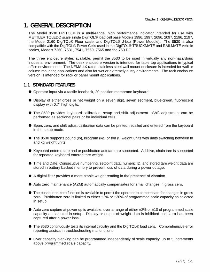
3.4 POWER REQUIREMENTSThe 8530 requires clean AC power with a true earth ground for reliable operation. The power line forthe 8530 must not be shared with equipment that generates line noise (such as motors, relays,heaters, copy machines, etc.). If adverse power conditions exits, a power line conditioner may berequired. Versions of the 8530 are available for 120 or 220/240 VAC operation.
The 8530 meets the NIST H-44, Canadian Gazette Part 1 and OIML-SP7/SP2 line voltage variationspecifications. The 8530-0001, 1001 and 2001 operate on 120 VAC (+10%, -15%) at a line frequencyof 60 Hz (±2%). The 8530-0011, 1011 and 2011 operate on 220/240 VAC (+10%, -15%) at a linefrequency of 50 Hz (±2%). Maximum power consumption is 75 watts.
AC Line Voltage Line Frequency in HzLine VoltageVariation
Specification
8530FactoryNumber Min Nominal Max Min Nominal Max
NIST H-44 100 120 130 59.5 60 60.5
Canadian 108 120 132 58.2 60 61.2
OIML-SP7/SP2
8530-00018530-10018530-2001 102 120 132 58.8 60 61.2
OIML-SP7/SP28530-00118530-10118530-2011
187204
220240
242264
49.049.0
5050
5151
Table 3-2 AC Line Voltage Variation Specifications
3.5 RADIO FREQUENCY INTERFERENCEThe 8530 meets U.S.A., Canadian and VDE 0871 class B requirements for RFI susceptibilityspecifications as listed with a maximum change of one displayed increment.
Specification Frequencies in MHz Field StrengthU.S.A.
CanadianVDE 0871 class B
27, 169 and 46427 and 464
27, 144, 169 and 464
3 volts/meter4 watts at 2 meters
3 volts/meter
Table 3-3 Radio Frequency Interference Susceptibility
3.6 APPEARANCE AND DIMENSIONSThe desk mount versions are a charcoal black painted, two piece, die cast aluminum enclosure. Thedesk enclosure is 8.4" (213 mm) high, 12.6" (320 mm) wide by 6.5" (165 mm) deep. The deskenclosure version weighs 15 lb (6.8 kg).
The rack versions are a charcoal black painted, sheet metal enclosure with a black painted, die castaluminum display bezel. The rack mount enclosure is 3.5" (89 mm) high, 17" (432 mm) wide by 9.3"(236 mm) deep. The rack enclosure version weighs 15.4 lb (7 kg).

Chapter 3: SPECIFICATIONS
(2/97) 3-3
Figure 3-1 Desk Enclosure Dimensions Figure 3-2 Rack Enclosure Dimensions
The wall versions are an unpainted, brushed stainless steel enclosure. The wall mount enclosure is11.3" (287 mm) high, 13.9" (353 mm) wide by 5.5" (140 mm) deep. The wall mount enclosure can bewall or column mounted. The wall mount version weighs 19 lb (8.6 kg).
Figure 3-3 Wall Mount Enclosure Front and Rear Dimensions
The rack enclosure versions can be mounted into a panel with the optional panel mount KOP (0917-0005). Refer to Figure 3-4 for panel mounting cutout dimensions.
Figure 3-4 Panel Mounting Detail For Rack Mount Enclosure

METTLER TOLEDO 8530 Service Manual
(2/97)3-4
3.7 JN PRINTER PORTThe 8530 provides the JN bi-directional serial port with RS-232C and 20 mA current loop interfaces.The JN port provides two modes of operation, demand and continuous. The demand mode output hasthree flexible ticket formats available that are compatible with METTLER TOLEDO Printers, Models8806, 8843, 8856 and 8860.
3.7.1 Continuous Output
The Toledo® continuous format output is transmitted after every display update, 15 times persecond. The continuous output is available from 1200 to 9600 baud. Refer to Section 6.7 for acomplete description of the continuous mode output.
3.7.2 Demand Mode Output
The demand output is subject to print interlock if enabled. The data output is available from 300to 9600 baud and can include expanded print format as well as an optional checksum character. Refer to Section 6.6 for a complete description of the demand mode output.
3.7.3 Remote ASCII Control Input
The 8530 can accept single ASCII characters into the serial port for remote CLEAR, PRINT, TAREand ZERO functions in either the demand or the continuous output mode.
3.8 OPTIONAL JW HOST PORTThe optional JW interface KOP provides a second bi-directional serial port with RS-232C andRS422/485 interfaces. The JW port provides three modes of operation: demand, continuous and hostmode. The JW port continuous and demand modes output selection is identical to the JN portcontinuous and demand mode output. The JW port can accept single ASCII characters into the serialport for remote CLEAR, PRINT, TARE and ZERO functions in either the demand or the continuousoutput mode.
Note: Only one serial port (either JN or JW) can be programmed for demand mode output, the other serialport must be configured for continuous mode (or host mode for JW port).
The JW port Host mode provides a master/satellite network protocol for interfacing with a hostcomputer. The host mode allows the host computer to read weight, status and setpoint data from thescale. The host mode also permits the host computer to upload and download tare and setpoint datato and from the 8530.
The JW port RS-232 interface can be used in the host mode for single scale interfacing applications.The JW port RS-422/485 interface can be used to connect up to eight 8530's to a single serial port ona host computer.
The host mode has been enhanced to provide greater functionality and troubleshooting capabilities.The host mode can now be used to read raw count output from individual Power cells in a vehiclescale, with error code information. Calibration data can also be uploaded and downloaded by meansof the host port.
The original 8530 host mode is still available by setup selection to provide compatibility with existingapplications.

Chapter 4: INSTALLATION INSTRUCTIONS
(2/97) 4-1
4. INSTALLATION INSTRUCTIONS4.1 UNPACKING
Inspect the shipping container and scale for loose or damaged parts. If any damage is found, immediatelynotify the freight carrier. Open the carton and continue the inspection, check for damaged or missing parts.
All versions are shipped with the following components:Model 8530 Technical Manual, TM008530 I01Model 8530 Operators Manual, OM008530 I02Single DLC Adapter Harness, PN 131612 00ABlank Key Overlay, PN 12281100A, Qty 4Capacity Label, PN 136595 00AQuality Feedback Card
The desk enclosure version also includes:Model 8530-00X1 Desk Enclosure IndicatorAC Line Cord, PN 109445 00ADE-9-P Load Cell Cable Connector, PN 117599 00BLoad Cell Connector Shell, PN 125384 00A5" of Embossed Copper Tape, PN 154360001
The wall enclosure version also includes:Model 8530-10X1 Wall Mount Enclosure IndicatorLoad Cell Cable Connector, PN 123492 00ATube, Gasket Sealant, PN 118251 00ACable Termination Instructions, PN 133528 00A
The rack enclosure version also includes:Model 8530-20X1 Rack Enclosure IndicatorAC Line Cord, PN 103867 00ADE-9-P Load Cell Cable Connector, PN 117599 00BLoad Cell Connector Shell, PN 125384 00A3" of Embossed Copper Tape, PN 154360001
4.2 OPENING THE ENCLOSUREOpen the enclosure as described next. Verify that all internal harnesses are securely fastened.
WARNING CAUTIONDISCONNECT ALL POWER TOTHIS UNIT BEFORE REMOVINGTHE FUSE OR SERVICING.
OBSERVE PRECAUTIONS FOR HANDLINGELECTROSTATIC SENSITIVE DEVICES.
4.2.1 Opening the Desk Enclosure
Removing the four screws from the corners of the rear cover opens the desk enclosure. Be careful notto damage the keyboard harness when removing the front cover. DO NOT over tighten the coverscrews when reinstalling them.
4.2.2 Opening the Wall Enclosure
The wall enclosure is opened by flipping the wing type handle of each fastener up and turning them 1800counter clockwise. Loosen the hinge fasteners on the left side last (be sure to loosen them both at thesame time to prevent jamming).
4.2.3 Opening the Rack Enclosure
Loosening the two front panel screws and sliding the chassis out of the outer case opens the rackenclosure. Remove the three inner cover retaining screws and the inner cover. Use caution reinstallingthe front panel screws to prevent cross threading.

METTLER TOLEDO 8530 Service Manual
(2/97)4-2
4.3 SELECT DigiTOL® LOAD CELL INTERFACEDigiTOL® load cells, referred to from here as "DLC", use one of two different communication methods,single load cell and multiple load cells. The 8530 provides both the single DLC interface and the multipleDLC interface. The single and multiple DLC interfaces use different wiring pinouts and communicationprotocols and are not compatible. Selection between the single and multiple DLC interfaces is performedby software selection and by installing a DLC adapter harness between the load cell extension harnessand the 8530 Main PCB.
The 8530 is compatible with the DigiTOL® Power Cells used in the DigiTOL® TRUCKMATE andRAILMATE vehicle scales, Models 7260, 7531, 7541, 7560, 7565 and the 760 DC when the multiple DLCadapter harness is installed.
The 8530 is compatible with single DigiTOL® Load Cell bases such as the Models 1996, 1997, 2096, 2097,2196, 2197, the Model 2160 DigiTOL® Floor Scale and the digital j-box, when the single DLC adapterharness is installed.
The 8530 is shipped with the multiple DLC adapter harness installed and is ready to be used withDigiTOL® Vehicle scales. If the 8530 is to be used with a single DLC base, the Model 2157 DigiTOL®floor scale or the digital j-box then the multiple DLC adapter harness must be removed from the 8530and the single DLC adapter harness, part number 131612 00A, must be installed between the loadcell extension harness and connector J3 on the 8530 Main PCB.
CAUTION!Single DLC scale bases, the Model 2160 Floor Scale and the digital j-box require the single DLC adapterharness be installed between the load cell extension harness and connector J3 on the 8530 Main PCB or elsedamage to the load cell may result.
REMOVE AC POWER FROM THE 8530 AND WAIT A MINIMUM OF 30 SECONDS BEFORE CONNECTING ORDISCONNECTING ANY HARNESSES FROM PCB'S OR LOAD CELLS OR ELSE DAMAGE MAY RESULT.
4.3.1 Install the Single DLC Harness, (If Required)
To convert the 8530 from the multiple DLC interface to the single DLC interface begin by removing ACpower to the 8530. Unplug the multiple DLC adapter harness from the J7 connector on the 8530 MainPCB. Disconnect the inline, nine pin connector end of the multiple DLC adapter harness from themating nine pin connector on the load cell extension harness. Refer to Figure 4-1.
Plug the inline, 9-pin connector end of the single DLC adapter harness (p/n 131612 00A), into themating connector on the load cell extension harness. Plug the 16 pin, dual row connector end of thesingle DLC adapter harness into connector J3 on the 8530 Main PCB. Refer to Figure 4-1.
Note: The desk enclosure version of the 8530 requires that the Main PCB be removed from the enclosurein order to change the DLC adapter harness.
4.3.2 Install the Multiple DLC Harness, (If Required)
To convert the 8530 from the single DLC interface to the multiple DLC interface, begin by removing ACpower to the 8530. Unplug the single DLC adapter harness from the J3 connector on the 8530 MainPCB. Disconnect the inline, nine pin connector end of the single DLC adapter harness from the matingconnector on the load cell extension harness. Refer to Figure 4-1.

Chapter 4: INSTALLATION INSTRUCTIONS
(2/97) 4-3
Plug the inline, nine pin connector end of the multiple DLC adapter harness, part number 131612 00A,into the mating connector on the load cell extension harness. Plug the 16 pin, dual row connector endof the multiple DLC adapter harness into connector J7 on the 8530 Main PCB. Refer to Figure 4-1.
Note: The desk enclosure version of the 8530 requires that the Main PCB be removed from the enclosure inorder to change the DLC adapter harness.
Figure 4-1 8530 Main PCB

METTLER TOLEDO 8530 Service Manual
(2/97)4-4
4.4 AC POWER VOLTAGE SELECTION, EXPORT VERSIONS ONLYUSA and Canadian versions of the 8530, factory numbers 8530-0001, 1001, and 2001 are shippedconfigured for 120 VAC input only and are not selectable for 220/240 VAC operation. The voltage selectioncard in the AC line filter assembly of the desk and rack enclosure versions MUST be to 120. If the voltageinput card in the line filter on these units is changed to anything other than 120 VAC the 8530 will notoperate.
General export versions of the 8530, factory numbers 8530-0011, 1011, and 2011 are shipped configuredfor 220 VAC operation and are selectable for 240 VAC operation.
4.4.1 Desk and Rack Enclosure Versions AC Line Voltage Selection
Remove the AC power cord from the AC filter assembly located on the right side of the Desk enclosureor on the rear of the Rack enclosure. Refer to Figure 4-2.
Slide the clear plastic fuse cover to the side, exposing the fuse. Pull the handle labeled FUSE PULLand remove the fuse. With the fuse removed, use a small screwdriver or similar object and gently prythe voltage selection card straight out of the AC filter assembly. A small hole in the card is provided toassist removal.
Insert the voltage selection card so that the desired voltage marking is readable and located on the leftside of the card. Reinstall the fuse in the fuse holder. Slide the fuse cover back into place and connectthe AC power cord to the AC filter assembly.
Figure 4-2 Export, Desk and Rack Version, AC Line Voltage Selection
4.4.2 Wall Enclosure Version AC Line Voltage Selection
AC voltage selection for the 8530-1011, is performed by rotating the voltage selection switch on the ACline filter fuse assembly, located in the bottom left corner of the 8530 enclosure. To switch between 220and 240 VAC, first remove AC power to the 8530 and open the enclosure. Next, insert the blade of asmall, flat-bladed screwdriver into the slot in the center of the voltage selection switch. Rotate theswitch clockwise to select 220 VAC, rotate the switch counter-clockwise to select 240 VAC. Refer toFigure 4-3.
Chapter 4: INSTALLATION INSTRUCTIONS
(2/97) 4-5
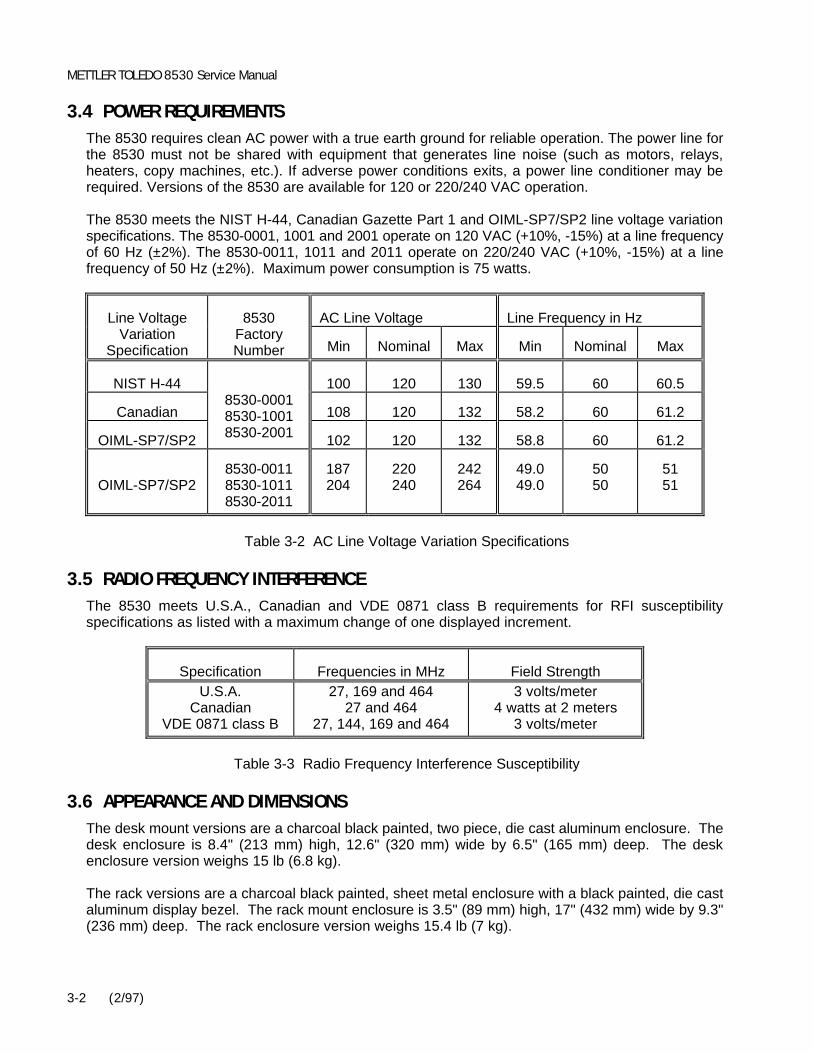
Figure 4-3 Export, Wall Mount Version, AC Line Voltage Selection
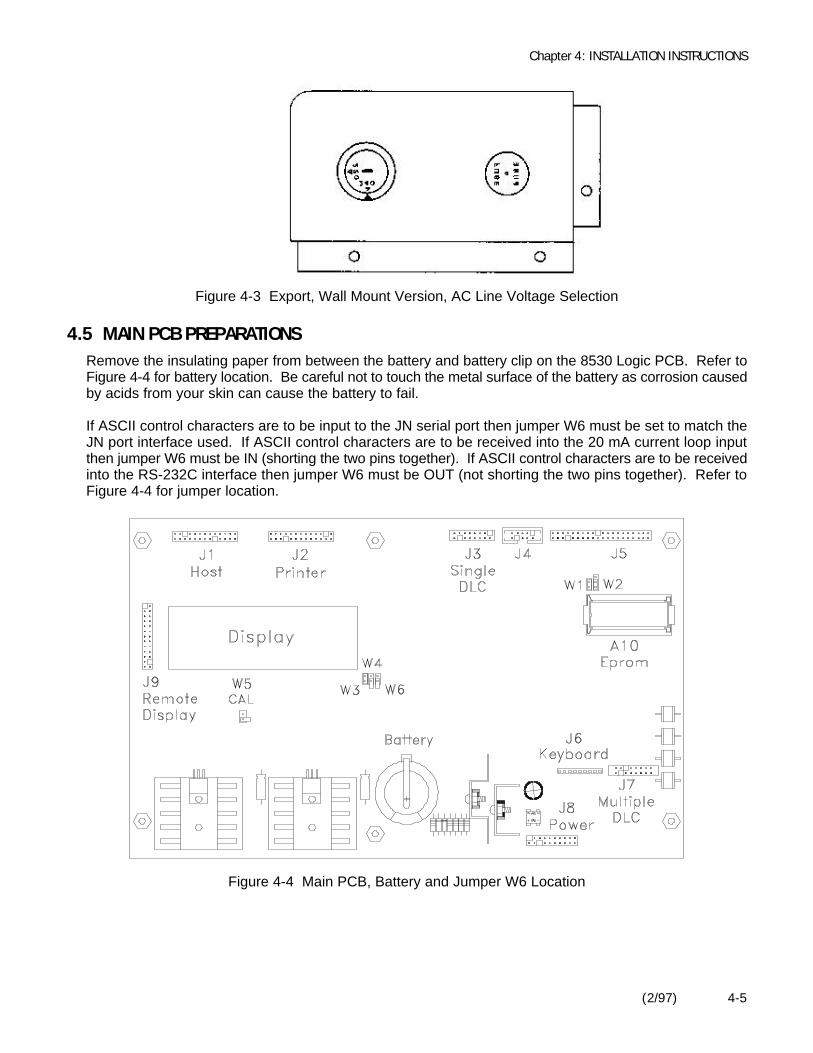
4.5 MAIN PCB PREPARATIONSRemove the insulating paper from between the battery and battery clip on the 8530 Logic PCB. Refer toFigure 4-4 for battery location. Be careful not to touch the metal surface of the battery as corrosion causedby acids from your skin can cause the battery to fail.
If ASCII control characters are to be input to the JN serial port then jumper W6 must be set to match theJN port interface used. If ASCII control characters are to be received into the 20 mA current loop inputthen jumper W6 must be IN (shorting the two pins together). If ASCII control characters are to be receivedinto the RS-232C interface then jumper W6 must be OUT (not shorting the two pins together). Refer toFigure 4-4 for jumper location.
Figure 4-4 Main PCB, Battery and Jumper W6 Location

METTLER TOLEDO 8530 Service Manual
(2/97)4-6
4.6 TERMINATE EXTERNAL WIRING
CAUTION!The 8530 is compatible with DigiTOL® load cells only. The 8530 MUST NOT beconnected directly to analog load cells as damage to the 8530 Main PCB may result. Analog load cells can be connected to the 8530 by using the digital j-box to convert theanalog load cells into a DigiTOL® load cell compatible interface.
Damage to the DigiTOL load cell or the 8530 Main PCB may result if the 8530 isconnected using the wrong DigiTOL load cell interface. Refer to Section 4.1.3 before connecting the 8530 to a scale base.
REMOVE AC POWER FROM THE 8530 AND WAIT A MINIMUM OF 30 SECONDSBEFORE CONNECTING OR DISCONNECTING ANY HARNESSES FROM PCB'S ORLOAD CELLS AS DAMAGE MAY RESULT.
4.6.1 Terminate Vehicle Scale Home Run Cable (If Used)
Verify that the multiple DLC adapter harness, part number 131613 00A, has been installed between theexternal load cell harness and the multiple DLC connector J7 on the 8530 Main PCB. Refer to Figure4-4 for connector J7 location. If the single DLC adapter harness, part number 131612 00A, is installedat connector J3 on the main PCB then refer to Section 4.1.3.
Refer to Section 6.3 of this manual and to the weighbridge installation manual for weighbridge andhome run cable wiring information.
4.6.2 Terminate Single DigiTOL® Load Cell Cable (If Used)
Verify that the single DLC adapter harness, part number 131612 00A, has been installed between theexternal load cell harness and the single DLC connector J3 on the 8530 Main PCB. Refer to Figure 4-4for connector J3 location. If the multiple DLC adapter harness, part number 131613 00A, is installedat connector J7 on the main PCB then refer to Section 4.1.3.
Refer to Section 6.3. of this manual for load cell cable termination instruction.
4.6.3 Terminate JN Printer Port Interface Cable
Refer to section 6.4 for interface cable termination instruction if JN printer port is used.
4.6.4 Terminate JW Host Port Interface Cable
Refer to section 6.5 for interface cable termination instruction if JW host port is used.

Chapter 4: INSTALLATION INSTRUCTIONS
(2/97) 4-7
4.7 NEW SCALE INSTALLATION NOTES4.7.1 DigiTOL® Vehicle Scale Installation Notes
When installing a new vehicle scale refer to the installation manual supplied with the DigiTOL®weighbridge.
Once the weighbridge is physically installed, configure the 8530 according to the recommended setupparameters in the quick setup reference chart in Section 4.2.3. Refer to the indicator setup section ofthe weighbridge installation manual for the correct scale capacity, increment size and number of PowerCells.
After the 8530 has been configured, perform the Power Cell addressing procedure, setup step [04]. If problems occur during the addressing procedure then refer to the troubleshooting procedure inSection 7 of this manual.
Once the load cells have been successfully addressed, let the 8530 warm up for 30 minutes and recordthe raw count output of each Power Cell using setup step [99]. Refer to the indicator setup section ofthe weighbridge installation manual for maximum raw count deviation and final shimming instructionsif necessary. Record and save the Power Cell raw count output readings after final shimming iscompleted, for future use.
Once the 8530 has been configured, the Power Cells have been addressed and correct Power Cellshimming has been verified, the scale is now ready for calibration. Perform sectional pair shift adjust,step [18], with either a weight cart or the rear axles of your test truck. Immediately after shift adjust iscompleted, before you exit the setup mode, perform the calibration procedure, step [19] using the sameweight used for shift adjust. Once the shift adjust and scale calibration have been performedsuccessfully the first time, the shift adjust and scale calibration steps can be accessed independentlywithout causing a problem.
Note: Steps [18] and [19] must be performed in order without leaving the setup mode, for first timeinstallations. Do not perform the calibration procedure, step [19], unless the shift adjust procedure, step[18], has been successfully performed at least once. Do not perform the zero or span adjust, steps [21]or [22], unless the calibration procedure, step [19], has been successfully performed at least once.
After the shift adjust and calibration procedures, steps [18] and [19], have been performed, exit thesetup mode and verify weighing performance. Some installations may require individual load cell shiftadjust to eliminate side to side errors.
If individual cell adjust is required, then select individual cell adjust, setup step [02 1], and repeat theshift adjust procedure, step [18]. A weight cart or a large fork lift truck that can concentrate the weightdirectly over the load cell being adjusted will be much more effective during shift adjustment than therear axle of a test truck.
If step [18] is unable to reduce shift errors to within required limits, use the manual shift adjustprocedure, step [96], to bring the shift errors within tolerance.
RECORD AND SAVE the calibration data from step [97] once scale calibration is completed. If the8530 Main PCB is replaced then the calibration data saved from step [97] of the old Main PCB can bereentered into the new Main PCB at step [97] and the scale will not require calibration.

METTLER TOLEDO 8530 Service Manual
(2/97)4-8
4.7.2 Single DLC, Model 2157, Model 2160/Digital J-box Installation Notes
Refer to the data plate located on the scale base for the recommended scale capacity and incrementsize. If you intend to use the recommended capacity and increment size printed on the data plate thenrefer to Section 4.8 for programming and calibration information.
The 8530 is capable of displaying up to a maximum of 60,000 displayed increments. If you intend touse an increment size that is smaller than the recommended increment size selection printed on thescale base data plate then the minimum increment size for the scale base must be determined beforecalibration. Refer to Section 4.7.2.1 for DigiTOL® J-Box minimum increment size. Refer to Section4.7.2.2 for Model 2157 DigiTOL® Floor Scale minimum increment size. Refer to Section 4.7.2.3 forBench and Portable Single DLC scale base minimum increment size.
Note: The minimum increment size selections listed in Sections 4.7.2.1, 4.7.2.2, and 4.7.2.3. are not legal-for-trade. The increment size selected for a scale used in a legal-for-trade application MUST NOT BESMALLER than the minimum increment size (e-min) listed on the scale base or load cell dataplate.
Note: Multi-range operation is also subject to the minimum increment size selection listed in Sections 4.7.2.1,4.7.2.2, and 4.7.2.3.
4.7.2.1 Minimum Increment Size For DigiTOL® J-Box Applications
Table 4-1 lists the minimum increment size possible for the DigiTOL® J-Box when connected to thefollowing Toledo/Masstron analog load cells. Find the individual capacity of the load cells you areconnecting to the DigiTOL® J-Box in Table 4-1 and compare the desired increment size to theminimum increment size listed.
Minimum Increment SizeRated Load CellCapacity in lb Load Cell Type
lb kg
5001,0003,0005,000
10,00020,00045,00050,00075,000100,000100,000
Bending BeamShear BeamShear BeamShear BeamShear BeamShear BeamShear BeamCap CheckShear BeamCap CheckDual Shear Beam
0.10.20.51.02.05.0
20.010.020.020.050.0
0.050.10.20.51.02.0
10.05.0
10.010.020.0
Table 4-1 DigiTOL® J-Box Minimum Increment Size

Chapter 4: INSTALLATION INSTRUCTIONS
(2/97) 4-9
4.7.2.2 Minimum Increment Size For Model 2157, 2160 DigiTOL® Floor Scale
Table 4-2 lists the minimum increment size possible for the Model 2157 DigiTOL® Floor scale. Findthe rated capacity of the scale base you are interfacing to in Table 4-2 and compare the desiredincrement size to the minimum increment size listed.
Minimum Increment SizeRated ScaleCapacity
in lb
Individual LoadCell Capacity
in lb lb kg
2,0005,000
10,00020,000
1,0003,0005,000
10,000
0.20.51.02.0
0.10.20.51.0
Table 4-2 Model 2157 DigiTOL® Floor Scale Minimum Increment Size
4.7.2.3 Minimum Increment Size for Bench and Portable Single DLC Scale Bases
Table 4-3 lists the minimum increment size possible for the DigiTOL® Bench and portable single DLCscale base models listed by factory number. Find the base you are connecting in Table 4-3 andcompare the desired increment size to the minimum increment size listed.
Minimum Increment SizeScale Base Factory # Load Cell
Capacity lb kg1996-00011997-0001 30 kg 0.0005 0.00051996-00022096-0002 60 kg 0.001 0.0005
1997-00022096-00032097-0001 100 kg 0.005 0.002
1996-00032096-0001 140 kg 0.001 0.0005
2096-00022096-00042097-0002 300 kg 0.005 0.005
2196-00012196-00032197-0001 500 kg 0.01 0.005
2196-00022196-00042197-0002 1000 kg 0.02 0.01
Table 4-3 Single DigiTOL® Load Cell, Minimum Increment Size

METTLER TOLEDO 8530 Service Manual
(2/97)4-10
4.8 PROGRAMMING AND CALIBRATION
WARNING CAUTIONONLY PERMIT QUALIFIED PERSONNEL TO
SERVICE THIS EQUIPMENT. EXERCISE CAREWHEN MAKING CHECKS, TESTS AND
ADJUSTMENTS THAT MUST BE MADE WITHPOWER ON. FAILING TO OBSERVE THESE
PRECAUTIONS CAN RESULT IN BODILY HARM.
OBSERVE PRECAUTIONS FORHANDLING ELECTROSTATIC
SENSITIVE DEVICES.
4.8.1 Keyboard Functions During Setup
The keyboard is redefined as shown while in the setup mode.
Numeric The numeric keys (0 - 9) are used to enter data as required.
1 Press the 1 key to access a sequence or to select (YES).
0 Press the 0 key to select (NO) or to skip a step. The 0 key is also used to display thenext selection when a menu of choices is presented.
CLEAR Press the CLEAR key to erase the current value and permit reentry of data.
ENTER Press the ENTER key to accept the displayed selection and to advance to the nextsetup step.
PRINT The PRINT key is used in step [97] to print just the calibration parameters.
ZERO Press the ZERO key to accept the displayed selection and back up to the previous setupstep.
4.8.2 Access the Setup Mode
Remove AC power from the 8530. Place the W5 jumper (marked CAL) to the IN position (shorting thetwo pins together), on the 8530 Logic PCB. Refer to Figure 4-1 for W5 jumper location. Apply ACpower to the 8530. After the power up display tests and the software part number and revision levelis displayed, the 8530 enters the setup mode. Double dashes [--] are displayed, indicating the 8530is in the setup mode.
Note: DO NOT remove the W5 (CAL) jumper or remove power from the 8530, while the 8530is in setup mode, unless the 8530 is at the double dash [--] display. If the setupmode is exited incorrectly then the 8530 may display an [E3] error code on power up. Refer to Section 7 of this manual for clearing error codes.

Chapter 4: INSTALLATION INSTRUCTIONS
(2/97) 4-11
4.8.3 Model 8530 Setup Quick Reference Chart
00 SCALE GROUP
01 Load Cell Type 0 = Single DigiTOL® Load Cell1 = Power Cell Vehicle Scales2 = Model 2157 or Digital J-box
02 Shift Adjust Mode 1 = Sectional Pairs0 = Independent DLC
03 Number of Load Cells (Note 3)04 Auto Address Power Cells (Note 3)05 Reset Shift Adjustment Values (Note 4)
10 CALIBRATION GROUP
11 Calibration Units 0 = kilograms1 = pounds
12 Linearity Compensation 0 = Linearity Disabled1 = Linearity Enabled
13 Autorange (Note 2) 1 = Single Range Mode2 = Double Range Mode3 = Triple Range Mode
14 Scale Capacity (Note 2)15 High Range Increment Size (Note 2)16 Mid Range Increment Size17 Low Range Increment Size18 Auto Shift Adjust Procedure (Notes 1 and 2)19 Calibration
20 ZERO AND FILTERING GROUP
21 Zero Adjustment22 Span Adjustment23 AZM Range (Note 2) 0 = Disable AZM
1 = AZM Within ±0.5 Division2 = AZM Within ±1.0 Division3 = AZM within ±3 Divisions
23A AZM in Net Mode 0 = AZM in gross mode only1 = AZM in net and gross mode
24 Powerup Zero Capture 0=Disable Zero Capture1=Zero Capture ±2%Capacity2=Zero Capture ±10%Capacity
24A Powerup Delay 0 = Display weight at powerup1 = Delay display 30 seconds
25 Pushbutton Zero Range 0 = Disable Pushbutton Zero1 = ±2% of Capacity2 = ±20% of Capacity
26 Motion Detect (Note 2) 0 = Disable Motion Detection1 = ±0.5 Increments2 = ±1.0 Increments3 = ±2 Increments4 = ±3 Divisions
27 Display Filtering 0 = Disable Filtering1 = Light Filtering2 = Light-Medium Filtering3 = Medium Filtering4 = Medium-Heavy Filtering5 = Heavy Filtering
27A Cell Filter (Note 2, 3) 0 = Disable Internal Cell Filter1 = Enable Internal Cell Filter
28 Overcapacity (Note 2) Blank at Capacity+5 Increments
29 Accumulator Mode 0 = Accumulator disabled1 = Accumulate Net Weight2 = Accumulate Gross Weight3 = Displayed Weight
30 TARE GROUP
31 Tare Mode 0 = Disable Tare1 = Autotare Only2 = Autotare and Keyboard tare
32 Tare Interlock (Note 2) 0 = Disable Tare Interlocks1 = Enable Tare Interlocks
33 Manual Tare Mode 0 = Manual Tare All Ranges1 = Low Range Only
34 Autoclear Tare 0 = Disable Autoclear Tare1 = Enable Autoclear Tare
35 Gross/Net Switching 0 = Gross/Net key disabled1 = Gross/Net key enabled
36 Function Key Enable 0 = Disable Function key1 = Enable all except setpoints2 = All functions enabled
37 Stored Tare Memory 0 = Memory Disabled1 = Memory Enabled
38 Memory Mode 0 = Permanent Memory1 = Inbound/Outbound Memory
Notes:1: Recommended default selections are shown in Bold Italics.2: These steps require specific selection for legal-for-trade applications.3: These steps are for Power Cell Vehicle Scales only and are skipped for other load cell types.4: These steps are for Model 2157 or digital j-box only and are skipped for other load cell types.

METTLER TOLEDO 8530 Service Manual
(2/97)4-12
4.8.3 Model 8530 Setup Quick Reference Chart Continued
40 JN PORT GROUP SELECTION
41 Output Data Format 0 = Continuous Output1 = Demand Output2 =<ENQ> Continuous Output
41A Status Bytes Mode 0 = Setpoint Data1 = Increment Data
42 Baud Rate 9600
43 Parity Selection 0 = No Parity1 = Odd Parity2 = Even Parity3 = Parity always a "0"
44 Checksum 0 = Disable Checksum1 = Enable Checksum
45 Stop Bits 1 = 1 stop bit2 = 2 stop bits
50 JW PORT GROUP SELECTION
51 Port Output 0 = Continuous output1 = Original Host Mode2 = Demand output3 =<ENQ> Continuous Output4 = Expanded Host Mode
51A Status Bytes Mode 0=Setpoint Data in continuous1=Increment Type in continuous
52 Baud Rate 4800
53 Parity Bit 0 = 7 data bits, no parity1 = 7 data bits, odd parity2 = 7 data bits, even parity3 = 8 data bits, no parity
54 Checksum Enable 0 = No checksum1 = Checksum enable
55 Stop Bits 1 = 1 stop bit2 = 2 stop bits
56 Host Port Address 02
57 MultiDrop Mode Select 0 = RS-485 (Multidrop)1 = RS-422 (Single Drop)
60 PRINTER DEMAND GROUP SELECTION
61 Clear Tare After Print 0 = Disable Autoclear1 = Enable Autoclear
62 AutoPrint/Interlock 0 = Demand Print1 = Single Print2 = Auto Print
63 Minimum Print 0 = No minimum1 = 10 increments2 = 100 increments3 = 500 increments
64 Net Sign Correction 0 = Normal Net Weight Printing1 = Net Sign Corrected Printing
65 Enable "STX" 0 = To Disable "STX"1 = To Enable "STX"
66 Weight Format 0= Single Line Displayed Weight1= Single Line Gross, Tare, Net2= Multiple Line Gross, Tare, Net
67 Expanded Size Print 0 = Normal Weight Print1 = Expanded Size Weight Print
68 Weight Units 0=Print "lb" or "kg"1=Print "g", gram units2=Print "oz", ounce units3=Print "oz t", Troy ounce units4 = Print "t", ton units5 = Disable weight units
69 Print I.D. 0 = Disable printing of I.D.1 = Print I.D.2 = Print I.D. expanded
71 Clear I.D. after Print 0 = Enable Autoclear of I.D.1 = Disable Autoclear of I.D.
72 Print C.N. 0 = Disable printing of C.N.1 = Enable printing of C.N.
73 Time/Date Format 0 = No Time and Date1 = MM DD YY2 = DD.MM.YY3 = YY MM DD4 = HH:MM PM MM DD YY5 = DD.MM.YY HH:MM6 = YY MM DD HH:MM
Notes:1: Recommended default selections are shown in Bold Italics.2: These steps require specific selection for legal-for-trade applications.3: These steps are for Power Cell Vehicle Scales only and are skipped for other load cell types.4: These steps are for Model 2157 or digital j-box only and are skipped for other load cell types.

Chapter 4: INSTALLATION INSTRUCTIONS
(2/97) 4-13
4.8.3 Model 8530 Setup Quick Reference Chart Continued
74 Demand Output Format 1 = WT, ID, T&D, CN2 = ID
T&DWT, CN
3 = IDT&D, CNWT
4 = IDT&DCNWT
5 = T&DIDCNWT
6 = T&DIDWT, CN
7 = ID, T&D, CNWT
8 = IDT&DCN, WT
80 INTERNATIONAL GROUP SELECTION
81 Analog/Display Verify 0 = Disable Verification(Note 5) 1 = Enable Verification
82 lb/kg Switching 0 = lb/kg switching Disabled1 = lb/kg Switching Enabled
83 Power-Up Weight Units 0 = Power-Up in kg1 = Power-Up in lb
84 Bracketed Weight Print 0 = Print weights brackets1 = Print weights with brackets
85 Manual Tare Legend 0=Print (TRH) after manual tare1=Print (PT) after manual tare
86 Remote ASCII Input 0 = ASCII input disabled1 = ASCII input enabled
87 Remote Pulse Input 0 = Pulse input Disabled1 = Print output on pulse2 = Zero scale on pulse3 = Tare scale on pulse
88 Zero Curser Mode 0 = Gross zero only1 = Gross and net zero
90 DIAGNOSTIC GROUP
91 Manual Load Cell Addressing (Note 3)92 Auto Replacement Load Cell Addressing (Note 3)93 Shift Adjust an Individual Cell or Sectional Pair (Note 3)94 Temporarily Set Shift Constants to "1" (Note 3)
95 Expanded Display Mode 0 = Normal Weight1 = Display Minor Increments
96 Manual Shift (Note 3) 0 = Manual shift adjust disabled1 = Manual shift adjust enabled
97 Access Calibration Data 0=Bypass short cut calibration1=Access short cut calibrationPrint=Print calibration constants
98 Set Default Parameters 0 = Skip default parameters1 = Set default parameters
99 Display Individual Load Cell Raw Count Output (Note 3)
Notes:1: Recommended default selections are shown in Bold Italics.2: These steps require specific selection for legal-for-trade applications.3: These steps are for Power Cell Vehicle Scales only and are skipped for other load cell types.4: These steps are for Model 2157 or digital j-box only and are skipped for other load cell types.5: Analog verify is for export Power Cell applications only.

METTLER TOLEDO 8530 Service Manual
(2/97)4-14
4.8.4 Setup Parameters
[00] ACCESS LOAD CELL CONFIGURATION AND ADDRESSING
Enter the digits "0" then "0" to access this group. The 8530 begins at step [01] and can advance as faras step [05] if Digital j-box is selected.
[01 1] Select Load Cell Type
This step selects the type of DigiTOL® load cells the 8530 is to be used with. Refer to Section 4.3 ofthis manual before connecting the 8530 to the load cells.
Selection Load Cell Type
012
Single DigiTOL® Load CellPower Cell Vehicle ScaleDigital J-box, Model 2160
Notes:Steps [02], [03], [04], and [05] are skipped if single DigiTOL® load cell is selected, [01 0].Step [05] is skipped if Power Cell Vehicle Scale is selected, [01 1].Step [03] is limited to 4 cells max and step [04] is skipped if digital j-box is selected, [01 2].
[02 1] Shift Adjust in Sectional Pairs
Power Cells can be shift adjusted either in sectional pairs or individually. Sectional pairs shift adjust isfaster and simpler than individual shift adjust. Individual shift adjust is used in installations that haveexcessive side to side shift errors.
Press:0 - Select Individual Power Cell Shift Adjust1 - Select Sectional Pairs Shift Adjust
Note: Shift adjust MUST be set to sectional pairs with 16 or more Power Cells.
[03 10] Number of Power Cells in Scale Base
Enter the total number of Power Cells used in the weighbridge. The 8530 can operate with up to 24Power Cells maximum. If more than 16 power cells are used the 8530 MUST use sectional pairs shiftadjust. The Auxiliary Power Supply must be installed if more than 10 NMOS Power Cells are used. Thedigital j-box will only accept entries of from 2 to 4 cells.

Chapter 4: INSTALLATION INSTRUCTIONS
(2/97) 4-15
[04 ] Automatic Power Cell Addressing
Before a Power Cell can be used in a scale base the Power Cell MUST have a unique addressprogrammed into it. All new load cells are sent from the factory with a default address of 240. Step [04]automatically prompts the technician through the addressing procedure for all of the load cells in thescale base. Automatic Power Cell addressing is normally begun with all Power Cells disconnected. Refer to the indicator setup section of the weighbridge installation manual for the correct location ofPower Cell addresses in the weighbridge.
Press:0 - To skip Power Cell addressing1 - To access Power Cell addressing
Note: Power Cell addressing is normally performed during initial installation ONLY! Addresses are storedin the Power Cell. Power Cells do not need to be readdressed if the 8530 Logic PCB is replacedor the software is upgraded. Once a Power Cell has been successfully addressed it should neverneed to be addressed again. IF A POWER CELL THAT HAS BEEN OPERATING IS NO LONGERCOMMUNICATING, DISPLAYING AN [E8] ERROR, THEN DO NOT TRY TO READDRESS THEPOWER CELL. THE PROBLEM IS MOST LIKELY DUE TO A BAD CABLE, A DEFECTIVEPOWER CELL, OR A DEFECTIVE 8530 LOGIC PCB. If a Power Cell has lost its address, then thePower cell is defective and MUST be replaced. The only reason to readdress a working Power Cellis if you wish to move it to a different location in the weighbridge.
The procedure for auto assigning Power Cell addresses is as follows:
Power down the 8530 and verify that all Power Cells are disconnected from the scale base. Placethe W5 CAL jumper on the 8530 Logic PCB to the IN position, (shorting the two pins together), andapply power to the 8530. Press the 0 key twice, the 8530 display will then show [02 1]. Press theENTER key two times until the 8530 is displaying [04]. Press the 1 key to access cell addressing. The 8530 will display [04 1] briefly and then display [Add 1]. At this time connect load cell #1 tothe scale and press the ENTER key.
The 8530 then displays [LC 1] while load cell #1 is being addressed. If the load cell is successfullyaddressed the 8530 will then display [Add 2] to prompt the technician to connect load cell #2 andrepeat the addressing procedure. This procedure is repeated until all remaining load cells have beenaddressed.
If the 8530 is unable to communicate with a load cell during the addressing procedure an [E8 XX] errorcode is displayed, (XX = load cell that was not addressed). Press the CLEAR key to clear the errorcode and reset the 8530 back to the [--] display. Refer to Section 7. of this manual for troubleshootinginformation.
Once the source of the cell communication problem is corrected then remove power to the 8530 andconnect all load cells that have already been successfully addressed. Enter the setup mode and restartstep [04]. The 8530 will check for the presence of correctly addressed load cells. When the 8530detects a missing load cell address, this display will hold on [04 XX] (XX = next load cell to beaddressed) for a few seconds then display [Add XX] to prompt the technician to connect load cell XXand continue the addressing procedure. This procedure is then repeated until all cells have beenaddressed.

METTLER TOLEDO 8530 Service Manual
(2/97)4-16
[05 ] ERASE SHIFT ADJUSTMENT VALUES
The step lets you erase any current shift adjust values that are stored in the digital j-box. This stepshould be performed when first installing a digital j-box.
Press:0 - Retain current shift adjustment values1 - Erase current shift adjustment values
[10] ACCESS SCALE CALIBRATION GROUP
Enter the digits "1" then "0" to access this group. The 8530 begins at step [11] and advances though step[19].
[11 0] WEIGHT UNITS
Select the weight units the 8530 will use during calibration and for display of weight. Setup step [F68]selects the weight units printed in the demand mode.
Selection Weight Units Units Symbol
01
kilogramspounds
kglb
[12 0] LINEARITY COMPENSATION
Linearity compensation corrects for nonlinearity in weighing performance of the load cell. This isaccomplished by recording a weight reading at zero, full scale capacity and at half scale capacity. Inorder for linearity compensation to work correctly, it is important to use test weight that are as close tothe programmed full scale and half scale capacity as possible.
Press:0 - Disable Linearity Compensation1 - Enable Linearity Compensation
[13 1] AUTORANGE® SELECTION
The 8530 can be programmed for one, two or three display increment sizes. Enter the number ofweight display ranges the 8530 is to use: [1], [2], or [3]. Refer to section 5.7. for a detailed descriptionof Autorange® operation.
Press:1 - Select Single Range Mode2 - Select Dual Range Mode3 - Select Triple Range Mode

Chapter 4: INSTALLATION INSTRUCTIONS
(2/97) 4-17
[14 ] [XXXXXX] SCALE CAPACITY
Enter the total scale capacity [XXXXXX] in the weight units selected in step [11]. Enter the desiredcapacity using the digits on the numeric keyboard of the 8530 then press the PRINT key. Press theCLEAR key to clear the display if an error is made during entry.
[15 X0] HIGH RANGE INCREMENT SIZE
The 8530 displays the current increment size and decimal point selection of the high range incrementsize. If the displayed data is not correct, press the "0" key until the desired decimal point position isdisplayed then press the increment size digit (either "1", "2" or "5") on the keyboard to terminate theentry. This will select both the decimal position and increment size in one step. The standardincrement size for vehicle scales is 20 lb, 10 kg, or 0.01 t. If Autorange® is being used with acombination rail/truck scale then select a high range increment size of 50 lb, 20 kg, or 0.02 t.
Press:0 - Toggles the display through all available decimal point positions.1 - Selects an increment size of 1 after the decimal point has been selected.2 - Selects an increment size of 2 after the decimal point has been selected.5 - Selects an increment size of 5 after the decimal point has been selected.
[16 X0] MID RANGE INCREMENT SIZE
The display will show the increment size and decimal point position of the mid range increment sizeused when the 8530 was last calibrated. If the displayed data is not correct, use the proceduredescribed for setup step [15] to select a new mid range increment size.
Note: Step [16] is skipped if single range weighing is selected, step [13 1].
[17 X0] LOW RANGE INCREMENT SIZE
The display will show the increment size and decimal point position of the low range increment sizeused when the 8530 was last calibrated. If the displayed data is not correct, use the proceduredescribed for setup step [15] to select a new low range increment size.
Note: Step [17] is skipped if single or dual range weighing is selected, step [13 1] or [13 2].
METTLER TOLEDO 8530 Service Manual
(2/97)4-18
[18] ACCESS AUTO SHIFT ADJUST
Shift adjustment is used to compensate for differences in weight readings as a load is applied atdifferent positions on the scale platform. For new installations, drive the test truck across theweighbridge three to five times in both directions to seat the Power Cells and receivers beforeperforming the shift adjust procedure.
Vehicle Scale Shift Adjust Procedure:
If the 8530 is not in the setup mode then power down the 8530. Place the W5 CAL jumper on the8530 Logic PCB to the IN position, (shorting the two pins together), and apply power to the 8530. The 8530 will then display [--]. Press the 1 key then the 8 key, the 8530 will then display [18 0].
Press:0 - Skip shift adjust procedure.1 - Access shift adjust procedure.
The 8530 displays [E SCL]. Verify the scale is empty and press the ENTER key.
The 8530 then counts down from [16 CAL] to [01 CAL] as zero reading is recorded.
The 8530 then displays [SEC 01] or [CELL 01]. Center the test cart (or rear axle of the test truck)over section 1 or cell 1. Make sure the test cart or truck axle is centered from side to side over thesection. After coming to a complete stop on the section, release the brakes. If the truck rolls, putthe truck in gear and shut off the engine rather than holding position with the brakes. Wait 15seconds after the truck stops moving to let the weighbridge settle, then press the ENTER key.
The 8530 then counts down from [16 CAL] to [01 CAL] as the weight reading for section 1 isrecorded.
The 8530 then displays [SEC 02]. Reposition the test cart (or test truck) over section 2 (Power Cells3 and 4) and continue as before. Repeat this procedure for each section in the weighbridge.
Notes: Some installations may require individual load cell shift adjust to eliminate side to sideerrors. If individual cell adjust is required, then select individual cell adjust, setupstep [02 1], and repeat the shift adjust procedure, step [18]. If individual cell adjustis used the 8530 will prompt for [CELL XX] instead of [SEC XX] (XX = Power Cell orsection number). Place the test cart directly over the Power Cell specified. A weightcart or a large fork lift truck that can concentrate the weight directly over the load cellor section being adjusted will be more effective during shift adjustment than the rearaxle of a test truck.
If step [18] is unable to reduce shift errors to within required limits then use themanual shift adjust procedure, step [96], to bring the shift errors within tolerance. Problems with shift adjustment are usually caused by: a mechanical bind in theweighbridge, an incorrectly shimmed weighbridge, or not concentrating the testweight over the section or Power Cell during shift adjust.

Chapter 4: INSTALLATION INSTRUCTIONS
(2/97) 4-19
Model 2160 DigiTOL® Floor Scale Shift Adjust Procedure:
If 8530 is not in the setup mode then power down the 8530. Place the W5 CAL jumper on the 8530Logic PCB to the IN position, (shorting the two pins together), and apply power to the 8530. The8530 will then display [--]. Press the 1 key then the 8 key, the 8530 will then display [18 0]. Press:
0 - Skip shift adjust procedure.1 - Access shift adjust procedure.
The 8530 then displays [E SCL]. Verify the scale is empty and press the ENTER key.
The 8530 then counts down from [16 CAL] to [01 CAL] as the zero reading is recorded.
The 8530 then displays [CEL 01]. Place the test weight over load cell #1 then press the ENTER key. Refer to Figure 4-5.
2 4
1 J-Box 3
Figure 4-5 Model 2157 Load Cell Location in Deck
The 8530 then counts down from [16 CAL] to [01 CAL] as the weight reading for load cell #1 isrecorded. The 8530 then displays [CEL 02]. Move the test weight to directly over load cell #2 andpress the ENTER key.
The 8530 then counts down from [16 CAL] to [01 CAL] as the weight reading for load cell #2 isrecorded. The 8530 then displays [CEL 03]. Move the test weight to directly over load cell #3 andpress the ENTER key.
The 8530 then counts down from [16 CAL] to [01 CAL] as the weight reading for load cell #3 isrecorded. The 8530 then displays [CEL 04]. Move the test weight to directly over load cell #4 andpress the ENTER key. The 8530 will then count down form [16 CAL] to [01 CAL] as the weight reading for load cell # 4 isrecorded.
[19 ] ACCESS CALIBRATION PROCEDURE
Full calibration is used to set the initial zero (initial) reference and to set span. Full calibration can beperformed either with a known vehicle weight or with certified test weights. If a known vehicle weightis used for full calibration, then span adjust, step [22], should be performed after calibration withcertified test weights to ensure accurate calibration.
Note: For Power Cell Vehicle Scale installations this step MUST be performed immediately afterperforming shift adjust, step [18], for the first time. Do not exit the setup mode or power downthe 8530 without first performing a full calibration, step [19], or else the shift adjust datacalculated in step [18] will be lost and an error code will be displayed. Full calibration is notrequired for subsequent shift adjust after a full calibration has been successfully performed atleast once.
METTLER TOLEDO 8530 Service Manual
(2/97)4-20
To perform full calibration:
If 8530 is not in the setup mode then power down the 8530. Place the W5 CAL jumper on the 8530Logic PCB to the IN position, (shorting the two pins together), and apply power to the 8530. The8530 will then display [--]. Press the 1 key then the 9 key, the 8530 will then display [19 0].
Press:0 - Skip calibration procedure.1 - Access calibration procedure.
The 8530 will follow one of two calibration procedure depending on how linearity compensationenable is selected, step [12]. If linearity compensation is enabled then the 8530 will prompt for anadditional calibration step. Linearity compensation will give the best results if test weights equal to100% and 50% of programmed capacity are used.
Calibration Procedure, Linearity Compensation Disabled (Step [12 0]
[E SCL] EMPTY SCALE
Remove all weights from the scale platform then press the ENTER key. The display then countsdown from 16 to 1 as a zero reference weight is recorded for the scale.
[Add Ld] ADD LOAD
Apply test weight to the scale platform. Press the ENTER key.
[ . ] ENTER TEST WEIGHT VALUE
Enter the known weight of the test truck or the value of the test weights, using the numeric keys onthe 8530 keyboard. Press the ENTER key to terminate entry. The test weight value entered mustagree with the increment size used by the scale. The display then counts down from 16 to 1 whilespan is recorded.
[CAL d] CALIBRATION DONE
This prompt is displayed for a few seconds to indicate that calibration was successful, then thedisplay returns to the [--] prompts.
Note: If an [E36] error code is displayed during calibration of a Power Cell® vehicle scale then checkthe shift adjust coefficients in step [97]. If the shift adjust coefficients are equal to zero[0.000000] then the 8530 will not calibrate. Either perform the shift adjust procedure [18] or entera shift adjust value of [1.000000] for each section or cell in step [97].
Note: Single DigiTOL® Load Cell Scale bases may perform an additional [E SCL] count down sequenceafter the [Add Ld] step if calibrated with an increment size smaller than the recommendedincrement size.

Chapter 4: INSTALLATION INSTRUCTIONS
(2/97) 4-21
Calibration Procedure, Linearity Compensation Enabled (Step [12 1])
[E SCL] EMPTY SCALE
Remove all weights from the scale platform then press the ENTER key. The display then countsdown from 16 to 1 as a zero reference weight is recorded for the scale.
[Add FL] ADD FULL LOAD
Apply full capacity test weight to the scale platform. Test weights used should be as close to 100%of full scale capacity as possible. Press the ENTER key.
[ . ] ENTER FULL TEST WEIGHT VALUE
Enter the value of the test weights, using the numeric keys on the 8530 keyboard. Press the ENTERkey to terminate entry. The test weight value entered must agree with the increment size used bythe scale. The display then counts down from 16 to 1 while span is recorded.
[Add LO] ADD LOW LOAD
Apply half capacity test weight to the scale platform. Test weights used should be as close to 50%of full scale capacity as possible. Press the ENTER key.
[ . ] ENTER LOW TEST WEIGHT VALUE
Enter the value of the test weights, using the numeric keys on the 8530 keyboard. Press the ENTERkey to terminate entry. The test weight value entered must agree with the increment size used bythe scale. The display then counts down from 16 to 1 while span is recorded.
[CAL d] CALIBRATION DONE
This prompt is displayed for a few seconds to indicate that calibration was successful, then thedisplay returns to the [--] prompts.
Note: If an [E32] error code is displayed during calibration of a Power Cell® vehicle scale then checkthe shift adjust coefficients in step [97]. If the shift adjust coefficients are equal to zero[0.000000] then the 8530 will not calibrate. Either perform the shift adjust procedure [18] or entera shift adjust value of [1.000000] for each section or cell in step [97].
Note: Single DigiTOL® Load Cell Scale bases may perform an additional [E SCL] count down sequenceafter the [Add Ld] step if calibrated with an increment size smaller than the recommendedincrement size.

METTLER TOLEDO 8530 Service Manual
(2/97)4-22
[20] ACCESS FILTERING, AZM GROUP
Enter the digits "2" then "0" to access this group. The 8530 begins at step [21] and advances though step[29].
Note: Steps [21] and [22] can't be accessed until the 8530 has been calibrated with step [19] and isdisplaying weight when the setup is entered.
[21 ] ZERO ADJUSTMENT
Press:0 - Skip zero adjustment.1 - Record the current weight as the new zero reference.
[22 ] SPAN ADJUSTMENT
This step adjusts the span reference recorded in step [19]. Place a known test weight on the scaleplatform before entering the setup mode.
Press:0 - Skip span adjustment.1 - Access span adjust. Enter the value of the weight on the scale using and press the PRINT
key. Span adjust value entered must agree with the increment size of the scale.
[23 3] AUTO ZERO MAINTENANCE (AZM)
AZM removes small changes in zero caused by temperature change or build up of material on theplatform. This step selects the range of weight around zero that AZM operates in. AZM will adjust forzero changes at the rate of 0.03 increments per second when the weight is within the AZM range. AZMwill operate up to total weight equal to the pushbutton zero range selected in setup step [25], ±2% or±20 of scale capacity.
Selection AZM Range Legal-For-Trade Applications
0123
AZM Disabled±0.5 Increment±1 Increment±3 Increment
Not ApplicableAnimal, Food and Retail ScalesAll other Industrial ScalesVehicle Scales
[23A 0] AZM IN NET WEIGHT MODE
If this step is enabled, AZM will operate anytime the weight on the scale is within the AZM rangeselected at step [23]. If this step is disabled then AZM is disabled in the net weight mode.
Press:0 - AZM in gross weight mode only1 - AZM in gross and net weight mode

Chapter 4: INSTALLATION INSTRUCTIONS
(2/97) 4-23
[24 1] AUTO ZERO CAPTURE AT POWER UP
If this step is enabled, the 8530 will attempt to capture zero at power up. Flashing [ E E E] or [-E E E]is displayed if the 8530 is unable to capture zero at powerup.
Press:0 - Disable Auto Zero Capture at Power Up1 - Enable Auto Zero Capture, limited to ± 2% of Scale Capacity2 - Enable Auto Zero Capture, limited to ± 10% of Scale Capacity
Note: USA and Canadian legal-for-trade applications limit zero capture at power up to ±2%.
[24A 0] POWERUP DISPLAY TIMER
If this step is enabled the weight display will remain blank and the cursors will blink for 30 seconds afterpowerup to allow the circuitry to warmup before displaying weight.
Press:0 - Disable Powerup Display Timer1 - Enable Powerup Display Timer
[25 2] PUSHBUTTON ZERO RANGE
Pushbutton zero recaptures the center of zero reference. This function is used to compensate formaterial build up on the scale. Zero capture is inhibited if the scale is in motion.
Press:0 - Disable Pushbutton Zero1 - Enable Pushbutton Zero Capture, limited to ± 2% of Scale Capacity2 - Enable Pushbutton Zero Capture, limited to ± 20% of Scale Capacity
Note: Canadian legal-for-trade applications are limited to ±2% pushbutton zero operation.
[26 4] MOTION DETECT WINDOW
The Model 8530 includes an stability detector (weight in motion) which requires three successive weightreadings within the motion detect window for a "no motion" signal. Zero, tare and demand modeprinting are inhibited during motion. Vehicle scales use selection 4, ±3 increments
Press:0 - Motion Detect Disabled, not legal-for-trade.1 - Motion Detected for weight change greater than ±0.5 Increment.2 - Motion Detected for weight change greater than ±1 Increment.3 - Motion Detected for weight change greater than ±2 Increment.4 - Motion Detected for weight change greater than ±3 Increment.

METTLER TOLEDO 8530 Service Manual
(2/97)4-24
[27 4] DISPLAY FILTERING RATE
The Model 8530 has a low pass, multi-pole vibration filter that is selectable for various conditions. Thedisplay settling time will be slowed as heavier filtering is selected. Valid selections are from 0 (nofiltering) to 5 (very heavy filtering). Filtering should be disabled for setpoint and filling applications thata require a fast response to weight change.
[27A 1] DigiTOL© LOAD CELL INTERNAL FILTER
This step disables the internal filter in a single DigiTOL® Load cell or digital j-box. The internal filtershould be disabled for setpoint and filling applications that a require a fast response to weight change.
0 - Disable internal load cell filter1 - Enable internal load cell filter
Note: This step is skipped if Power Cell load cell type is selected, step [01 1].
[28 ] [XXXXXX] OVERCAPACITY BLANKING VALUE
Enter the weight value [XXXXXX] at which the 8530 indication will blank over capacity. Press theENTER key to accept entry. Legal-for-trade applications must not exceed 105% of scale capacity. Default selection is capacity plus five increments.
[29 0] SCALE ACCUMULATOR
The scale accumulator adds the selected weight data to the total and subtotal accumulators when datais printed.
Press:0 - Accumulator Disabled1 - Accumulate Net Weight2 - Accumulate Gross Weight
Note: The FUNCTION key must be enabled, setup step [36 1] or [36 2], and print interlock or autoprintmust be selected, setup step [62 1] or [62 2], to permit accumulation. Units switching shouldbe disabled, setup step [82 0], when accumulation is used.
[30 ] TARE AND DISPLAY TIMER GROUP
Enter the digits "3" then "0" to access the tare and display group. The 8530 begins at step [31] andadvances through step [39].
[31 2] Tare Mode
Tare is used to subtract the empty weight of the container or vehicle from the gross weight on the scale. Tare is inhibited if the scale is in motion. Refer to Section 5 for tare explanation.
Press:1 - Tare Disabled.2 - Pushbutton Tare Enabled, Keyboard Tare Disabled.3 - Pushbutton Tare Enabled, Keyboard Tare Enabled.

Chapter 4: INSTALLATION INSTRUCTIONS
(2/97) 4-25
[32 0] TARE INTERLOCKS
Tare interlocks meet legal-for-trade requirements by including the following restrictions:Tare weights can be cleared only at gross zero. Tare can only be entered when the scale is the grossmode. Keyboard tare can be entered only at gross zero. Previous tare values must be cleared beforea new tare value can be entered. Multiple or chain tares are inhibited.
Press:0 - Disable Tare interlocks.1 - Tare interlock enabled.
Note: Tare interlocks should be disabled for setpoint or filling applications.
[33 0] KEYBOARD TARE IN LOW RANGE ONLY
Press:0 - Keyboard tare is allowed up to total (high range) scale capacity.1 - Keyboard tare may not exceed the low weight range capacity.
[34 0] AUTOCLEAR TARE
Press:0 - Disable Autoclear Tare.1 - Tare is automatically cleared when weight on the scale returns to within ±0.25 increments of
gross zero.
[35 1] GROSS/NET SWITCHING
Gross/net switching permits the operator to display the gross weight on the scale without losing thecurrent tare weight. Press the GROSS/NET key to toggle the display between the gross and net weight.
Press:0 - Disable GROSS/NET key.1 - Enable GROSS/NET key.
Note: GROSS/NET key is disabled if Autorange® is selected, step [13 2] or [13 3].
[36 1] FUNCTION KEY ENABLE
This step selects the functions that can be accessed through the Function mode during normaloperation. Time, date, consecutive numbering, and setpoints can only be accessed by using theFUNCTION key.
Press:0 - Disable FUNCTION key.1 - Enable FUNCTION key for all Functions except Setpoints.2 - Enable FUNCTION key for all Functions.
METTLER TOLEDO 8530 Service Manual
(2/97)4-26
[37 0] STORED TARE MEMORY ENABLE
This step enables the MEMORY key and permits up to 10 tare weights to be stored in memory. Storedtare weights can be used for inbound/outbound weighing transactions or for one pass permanent storedtare weighing.
Press:0 - Disable MEMORY key.1 - Enable MEMORY key.
[38 0] MEMORY MODE
This step switches between permanent stored tare weights and temporary inbound/outbound weightmemories. If temporary inbound/outbound memories is selected, the operator stores an inbound weightinto the next available memory location by pressing the MEMORY key followed by the PRINT key. Ifthe permanent stored tare weight mode is selected the operator selects the memory location the tareweight is to be stored into.
Press:0 - Permanent Memory.1 - Inbound/Outbound Temporary Memory.
[40 ] JN PORT GROUP
Enter the digits "4" then "0" to access the JN port group. The 8530 begins with step [41] and advancesthrough step [45].
[41 1] OUTPUT DATA FORMAT
The JN port supplies three modes of data output: continuous, demand or <Enq> continuous.
The continuous mode is a fixed format message of weight and status information output every displayupdate. The continuous mode is normally used with remote displays, setpoint controllers orBCD/Analog converters.
The demand mode output is a configurable format output that is normally used to drive a printer. Thedemand mode data is output only when a print request occurs either by pressing the PRINT key, anautoprint function or by an external print request. Demand mode output is inhibited if the weight on thescale is unstable, out of range or if zero has not been captured after powerup.
The <Enq> continuous mode is a variation of the continuous output mode that is intended for interfacingto computers. The computer sends an ASCII <Enq>, hex 05, to request one continuous format output. The 8530 will only output data when requested by the computer.
Press:0 - Select Continuous Format Output1 - Select Demand Mode Output2 - Select <Enq> Continuous Format Output

Chapter 4: INSTALLATION INSTRUCTIONS
(2/97) 4-27
[41A 0] JN PORT CONTINUOUS FORMAT STATUS BYTE MODE SELECT
The 8530 continuous output includes three status bytes that indicate the operating conditions in the8530. There are two different versions of the status bytes, setpoint and nonsetpoint. The 3015 setpointcontroller requires setpoint mode status bytes. The 9325 Analog Output converter requires nonsetpointmode status bytes.
Press:0 - Setpoint Mode Status Bytes1 - NonSetpoint Mode Status Bytes
Note: This step is skipped if the JN port is not configured for continuous.
[42 9600] BAUD RATE
Select the desired baud rate for the JN port by toggling through the available selections using the 0 key. When the desired baud rate is displayed, press the 1 key or the ENTER key to accept the selection. Baud rate selections are: 300, 1200, 2400, 4800 and 9600.
[43 2] DATA BITS, PARITY BIT
Select the desired data format for the JN port. METTLER TOLEDO products normally use 7 data bits,even parity. 7 data bits, even parity is required for Models 307, 8806 and 8860 printers to operate.
Press:0 - 7 Data Bits, No Parity Bit1 - 7 Data Bits, Odd Parity Bit2 - 7 Data Bits, Even Parity Bit3 - 8 Data Bits, No Parity Bit
[44 0] CHECKSUM
Checksum is used to detect errors in the transmission of data. Checksum is defined as the 2'scomplement of the seven low order bits of the binary sum of all characters preceding the checksumcharacter, including the <STX> and <CR> characters. The checksum calculation for multiple lines ofdata includes the <LF> character from the previous line of data.
Press:0 - Disable Checksum1 - Enable Checksum
[45 1] STOP BITS
Press:1 - Select 1 stop bit.2 - Select 2 stop bits.

METTLER TOLEDO 8530 Service Manual
(2/97)4-28
[50 ] JW PORT GROUP
Enter the digits "5" then "0" to access the JW port group. The 8530 begins with step [51] and advancesthrough step [55]. If host mode is selected then steps 56 and 57 are accessible.
[51 0] OUTPUT DATA FORMAT
The JW port supplies the continuous, demand and <Enq> continuous modes the same as the JN port. In addition the JW port adds a host interface mode. The host interface mode has been enhanced withextended features to permit remote troubleshooting. The original 8530 host mode is still available forcompatibility with existing applications.
Press:0 - Select Continuous Format Output1 - Select Original Host Mode2 - Select Demand Mode Output3 - Select <Enq> Continuous Format Output4 - Select Enhanced Host Mode
Note: The 8530 will permit only one of the two serial ports to be configured for demand mode output. Bothports can be configured for continuous mode without any conflict.
[51A 0] JW PORT CONTINUOUS FORMAT STATUS BYTE MODE SELECT
The 8530 continuous output includes three status bytes that indicate the operating conditions in the8530. There are two different versions of the status bytes, setpoint and nonsetpoint. The 3015 setpointcontroller requires setpoint mode status bytes. The 9325 Analog Output converter requires nonsetpointmode status bytes.
Press:0 - Setpoint Mode Status Bytes1 - NonSetpoint Mode Status Bytes
Note: This step is skipped if the JW port is not configured for continuous mode.
[52 4800] Baud Rate
Select the desired baud rate for the JW port by toggling through the available selections using the 0 key. When the desired baud rate is displayed, press the 1 key or the ENTER key to accept the selection. Valid baud rate selections are: 300, 1200, 2400, 4800 and 9600.
[53 2] DATA BITS, PARITY BIT
Select the desired data format for the JW port. METTLER TOLEDO products normally use 7 data bits,even parity. 7 data bits, even parity is required for Models 307, 8806 and 8860 printers to operate.
Press:0 - 7 Data Bits, No Parity Bit1 - 7 Data Bits, Odd Parity Bit2 - 7 Data Bits, Even Parity Bit3 - 8 Data Bits, No Parity Bit

Chapter 4: INSTALLATION INSTRUCTIONS
(2/97) 4-29
[54 0] CHECKSUM
Checksum is used to detect errors in the transmission of data. Checksum is defined as the 2'scomplement of the seven low order bits of the binary sum of all characters preceding the checksumcharacter, including the <STX> and <CR> character. The checksum calculation for multiple lines ofdata includes the <LF> character from the previous line of data.
Press:0 - Disable Checksum1 - Enable Checksum
[55 1] STOP BITS
Press:1 - Select 1 stop bit.2 - Select 2 stop bits.
[56 2] HOST PORT ADDRESS
This step selects the address the 8530 will respond to in the host interface mode. The 8530 host portcan be used in a multidrop network. Each 8530 on the network must have a unique address from 2 to9 inclusive. Press the key that corresponds to the desired address.
[57 0] HOST PORT MULTI-DROP MODE SELECT
The JY port supplies both RS-232 and RS-422/485 serial interfaces. The RS-422/485 interface can beused in either a four wire, full duplex, single-drop mode or a two wire, half duplex, multi-drop mode. This selection has no effect on the RS-232 host mode interface.
Press:0 - Select RS-485 multi-drop host interface mode.1 - Select RS-422 single-drop host interface mode.
Note: Steps [56] and [57] are skipped if JY port is configured for demand or continuous mode.
[60 ] DEMAND MODE OUTPUT GROUP
Enter the digits "6" then "0" to access the demand mode output group. The 8530 begins with step [61] andadvances through step [75]. Step 70 is skipped. If neither serial port is selected to demand mode thenonly steps [61], [62] and [63] are accessible, all other steps are skipped.
[61 0] AUTOCLEAR TARE AFTER PRINT
Press:0 - Tare is retained after printing, tare must be manually cleared.1 - Tare is automatically cleared after printing.

METTLER TOLEDO 8530 Service Manual
(2/97)4-30
[62 0] PRINT INTERLOCK/AUTOPRINT
Print interlock prevents repeat printing. If enabled, print interlock requires that the weight on the scalereturn to zero (or below the minimum print selection) and then settle to a weight greater than theminimum print selection before a subsequent print request is acted on.
Autoprint causes a print request to occur every time the weight on the scale settles on a positive valuelarger than the minimum print selection. DO NOT USE AUTOPRINT WITH A MINIMUM PRINTSELECTION OF 0, THIS WILL CAUSE ERRATIC OPERATION OF AUTOPRINT.
Press:0 - Normal Print1 - Select Print Interlock2 - Select Autoprint
[63 0] MINIMUM PRINT
The displayed weight must exceed the minimum print selection to allow a print function to occur. Minimum print also controls resetting autoprint and print interlock.
Press:0 - No Minimum Print1 - Minimum Print = 10 Increments2 - Minimum Print = 100 Increments3 - Minimum Print = 500 Increments
NOTE: Minimum print must be set to a non-zero value for autoprint to operate properly.
[64 0] NET SIGN CORRECTION
This step allows storage of a gross weight as well as a tare weight in the tare register. When the tareweight value is larger than the weight currently on the scale, the demand mode printer output isrearranged so that the larger value is the gross weight, the smaller value is the tare weight and the netdifference is positive. The display will show a negative net weight value but the data printed is apositive net weight.
Press:0 - Net sign correction is disabled.1 - Net sign correction is enabled.
[65 1] ENABLE STX CHARACTER
Demand mode output normally has an ASCII Start of Text <STX> character, hex 02, at the beginningof the data transmission. The leading <STX> character can be inhibited for application that are notcompatible with the <STX> character. The <STX> character is required for use with Mettler-ToledoScale Printers Models 307, 8806 and 8860.
Press:0 - Do not sent <STX> character.1 - Send the <STX> character.

Chapter 4: INSTALLATION INSTRUCTIONS
(2/97) 4-31
[66 0] WEIGHT DATA LINE FORMAT
This step selects whether the 8530 will print displayed weight (gross or net) or gross, tare and netweight. This step also selects single or multiple line printing.
Press:0 - Print displayed weight only.1 - Print gross, tare and net weight on a single line.2 - Print gross, tare and net weight on separate lines.
[67 0] EXPANDED SIZE WEIGHT PRINT ENABLE
This step selects whether an ASCII shift out <SO>, and an ASCII shift in <SI>, character is inserted inthe data transmission to select double width printing for the gross weight field (net weight field if a tarehas been taken). Model 307, 8804, 8806, 8855, 8856 and 8860 printers use the <SO><SI> charactersto select expanded size printing.
Press:0 - Disable expanded size printing.1 - Enable expanded size printing.
[68 0] PRINTED WEIGHT UNIT DESCRIPTION
This step selects the weight unit symbol that will be printed immediately after the weight fields.
Press:0 - Print "lb" or "kg" weight units as selected by display weight units.1 - Print "g" for gram weight units.2 - Print "oz" for ounce weight units.3 - Print "oz t" for troy ounce weight units.4 - Print "t" for ton weight units.5 - Disable weight units printing.
Note: Selections 1 through 5 disable lb/kg switching and extinguish the weight units cursor.
[69 1] PRINT ID ENABLE
This step selects whether the identification ID is printed. This step also permits the ID field to be printedwith the ASCII <SO> and <SI> characters to select double width printing for ID
Press:0 - Disable ID printing.1 - Print ID.2 - Print ID with expanded size print.
[71 0] CLEAR ID AFTER PRINT
Press:0 - ID must be manually cleared.1 - ID is automatically cleared after a print.

METTLER TOLEDO 8530 Service Manual
(2/97)4-32
[72 1] ENABLE CONSECUTIVE NUMBERING
Press:0 - Disable consecutive numbering.1 - Enable consecutive numbering.
[73 0] Time/Date Format Selection
This step selects the time and date format printed. Time is entered in Function 6 as 24 hour militarytime. Date is entered in Function 7 in the format selected here.
Press:0 - No TIme and Date1 - MM DD YY2 - DD.MM.YY3 - YY MM DD4 - HH:MM PM MM DD YY5 - DD.MM.YY HH:MM6 - YY MM DD HH:MM
Note: Selection 4 is a 12 hour time format with AM or PM. Other selections are 24 hour format.
[74 4] DEMAND OUTPUT FORMAT
This step selects the order that data is printed in the demand mode output. The weight field is eitherdisplayed weight or gross, tare and net weight in the format selected in step [66].
Press:
1 - WT, ID, T&D, CN
2 - IDT&DWT, CN
3 - IDT&D, CNWT
4 - IDT&DCNWT
5 - T&DIDCNWT
6 - T&DIDWT, CN
7 - ID, T&D, CNWT
8 - IDT&DCN, WT
Note: WT = weight fields, CN = consecutive numbering, T&D = time and date, ID = Identification.
Chapter 4: INSTALLATION INSTRUCTIONS
(2/97) 4-33
[80 ] INTERNATIONAL GROUP
Enter the digits "8" then "0" to access the demand mode output group. The 8530 begins with step [81] andadvances through step [89A].
[81 0] ANALOG AND DISPLAY VERIFY
European legal-for-trade applications require analog and display verification. The display testcontinuously checks the display segments for proper functioning, an [E5] error code is displayed if thedisplay verify test is failed. The analog verify test is a check on the analog to digital converters in thePower cells. The analog verify test is performed every four hours, an [E6] error code is displayed if theanalog verify test is failed.
Press:0 - Disable analog/display verify tests.1 - Enable analog/display verify tests.
[82 0] lb/kg UNITS SWITCHING
Press:0 - Disable lb/kg switching1 - Enable lb/kg switching
Note: lb/kg switching is inhibited until zero has been captured after power up. lb/kg switching shouldbe disabled for accumulation, setpoint or stored tare applications. If power up kg is selected andlb/kg switching is disabled the decimal point in the demand mode output will be replaced with acomma
[83 1] POWERUP WEIGHT UNITS
Press:0 - Select kg powerup weight units.1 - Select lb powerup weight units.
Note: If power up kg is selected and lb/kg switching is disabled the decimal point in the demand modeoutput will be replaced with a comma
[84 0] MEASURED WEIGHT BRACKETED PRINTING
European legal-for-trade applications require a leading "<" and a trailing ">" bracket around printedweights if the weight is an actual measured value rather than a keyboard "hand" entered value. If boththe gross and tare weight values are actual, measured values then the net weight field will also havebrackets printed around it.
0 - Disable Measured Weight Brackets.1 - Enable Measured Weight Brackets.

METTLER TOLEDO 8530 Service Manual
(2/97)4-34
[85 0] PRINT "PT" FOR KEYBOARD ENTERED TARE
Certain export legal-for-trade applications require printing the abbreviation "TRH" after keyboard "hand"entered tare weights and the abbreviation "NETC" after net weights that result from keyboard enteredtare. German legal-for-trade applications use the abbreviation "PT" to indicate hand (keyboard) enteredtare. "THR", "PT" and "NETC" abbreviations are only printed if power up kg with lb/kg switchingdisabled is selected, [82 0] and [83 0].
0 - Print "TRH" after hand entered tare.1 - Print "PT" after hand entered tare.
[86 0] REMOTE ASCII INPUT CHARACTER
Both the JN and JW ports on the 8530 can be use to accept ASCII control characters to emulate theCLEAR, PRINT, TARE and ZERO keys on the 8530 keyboard.
Note: The W6 jumper on the 8530 Main PCB MUST be (OUT), not shorting the pins together, for the RS-232 interface of the JN serial port to accept ASCII characters.
Press:0 - Disable ASCII input for both JN and JW port.1 - Enable ASCII input for both JN and JW port.
[87 1] CONTACT CLOSURE INPUT
The JN port 20 mA current loop input can be used as a contact closure input to emulate the PRINT,TARE or ZERO keys on the 8530 keyboard. The contact closure input is a momentary contact (0.3 to3 seconds). The contact closure input must be disabled for ASCII character input to the JN port, [86 1]. Refer to Section 6.2. for wiring information on the contact closure input.
Press:0 - Disable contact closure input.1 - Select remote PRINT key function.2 - Select remote ZERO key function.3 - Select remote TARE key function.
[88 0] NET ZERO CURSOR
Press:0 - Zero cursor is illuminated at gross zero only.1 - Zero cursor is illuminated at both gross and net zero.
Notes: US and Canadian legal-for-trade applications require zero cursor at gross zero only. Australian legal-for-trade applications require zero cursor at gross and net zero.

Chapter 4: INSTALLATION INSTRUCTIONS
(2/97) 4-35
[90 ] DIAGNOSTICS GROUP
The steps in diagnostics are accessed individually. The diagnostics group includes steps [91] through [99]. Enter the digits of the specific step you wish to access. The diagnostic steps are normally accessed onlyduring initial installation or in the event of a malfunction. Diagnostic steps [91], [92], [93], [94] and [96]are accessible for Power Cell vehicle scale bases only.
[91] MANUAL ADDRESSING AN INDIVIDUAL POWER CELL (Power Cell Vehicle Scales Only)
Step [91] is used to manually force an address into a Power cell that already has been addressed. Step[91] can also be used to clear the addresses of all Power cells to the factory default address of 240. An [E8] error code is displayed if step [91] is unsuccessful in addressing a Power cell.
With the 8530 displaying [--], Press the 9 then the 1 key. The 8530 then displays [91].
Press:0 - To skip manual Power cell addressing and return to double dash display, [--].1 - To access manual Power cell addressing and advance to the [LC OFF] display.
[LC OFF] LOAD CELL POWER OFF
When [LC OFF] displayed, the 8530 has removed all power to the Power cells. Disconnect allPower cells except the Power cell that is to be readdressed. Press the ENTER key.
[CELL] ENTER CELL ADDRESS
Enter the new address (from 01 to 24) for the Power cell. Enter an address of [00] to readdress thepower cell to the default factory address of 240.
Note: If step [91] is accessed with more than one Power cells connected, then the Power cell with thecurrent highest address is readdressed. If [00] is entered for a new address at the [CELL] displayprompt, then all Power cells connected to the 8530 are readdressed to the default factory addressof 240.
[LC OFF] LOAD CELL POWER OFF
When [LC OFF] is displayed, the 8530 has removed all power to the Power cells. If finished withaddressing Power cells then reconnect all Power cells. Press the ENTER key. The 8530 will thenreturn to the double dash [--] prompt. If more Power cells are to be addressed then reenter [91].
Note: Power Cell addressing is normally performed during initial installation ONLY! Addresses are storedin the Power Cell. Power Cells do not need to be readdressed if the 8530 Logic PCB is replaced orthe 8530 software is upgraded. Once a Power Cell has been successfully addressed it should neverneed to be addressed again. If a Power Cell has lost its address, then the Power cell is defectiveand MUST be replaced. The only reason to readdress a working Power Cell is if you wish to moveit to a different location in the weighbridge.
IF A POWER CELL THAT HAS BEEN OPERATING IS NO LONGER COMMUNICATING,DISPLAYING AN [E8] ERROR, THEN DO NOT TRY TO READDRESS THE POWERCELL. THE PROBLEM IS MOST LIKELY DUE TO A BAD CABLE, A DEFECTIVEPOWER CELL, OR A DEFECTIVE 8530 LOGIC PCB.

METTLER TOLEDO 8530 Service Manual
(2/97)4-36
[92] AUTOMATIC ADDRESSING A REPLACEMENT POWER CELL (Power Cell Vehicle Scales Only)
This step is used to address a replacement Power Cell. This step automatically addresses a new(default address of 240) Power Cell to the same address as the Power Cell that is being replaced. Thisstep will work correctly only if there is only one Power cell to be replaced and if the replacement PowerCell has an address of 240. If more than one Power cell is to be replaced or the replacement PowerCell has already been addressed then use step [91] to manually address the replacement Power cell.
With the 8530 displaying [--], Press the 9 then the 2 key. The 8530 then displays [92].
Press:0 - To skip automatic Power cell addressing and return to double dash display, [--].1 - To access automatic Power cell addressing and advance to the [LC OFF] display.
[LC OFF ] LOAD CELL POWER OFF
When [LC OFF] is displayed, the 8530 has removed all power to the Power cells. Disconnect thedefective Power cell and connect the replacement Power cell.
Press the ENTER key. The 8530 applies power to the Power cells. The 8530 then checks for amissing cell address. Once the 8530 has identified the missing Power cell address it then programsthe address into the replacement Power Cell. After the replacement Power Cell has been installedand addressed then the perform step the automatic single section shift adjust, step [93], for thereplacement Power cell.
[93] AUTOMATIC SINGLE SECTION SHIFT ADJUST (Power Cell Vehicle Scales Only)
Individual automatic shift adjust provides the ability to perform a shift adjust for a single section (orindividual Power Cell if step individual cell shift adjust mode has been selected, step [02 0]). Shiftadjust does not require the use of certified test weights, but the load used must be concentrated directlyover the section or cell for best results.
With the 8530 displaying [--], Press the 9 then the 3 key. The 8530 then displays [93].
Press:0 - To skip automatic single section shift adjust and return to double dash display, [--].1 - To access automatic single section shift adjust procedure.
[SEC ] or [CELL ] ENTER SECTION OR CELL TO BE SHIFT ADJUSTED
Enter the section or Power cell address to be shift adjusted and press the ENTER key.
[E SCL] EMPTY SCALE
Remove all weights from the scale platform then press the ENTER key. The display then countsdown from 16 to 1 as a zero reference weight is recorded for the scale.

Chapter 4: INSTALLATION INSTRUCTIONS
(2/97) 4-37
[LOAD XX] PLACE THE TEST LOAD OVER SECTION OR CELL TO BE SHIFT ADJUSTED
Place the load to be used for the shift adjustment directly over the specified section or Power celland press the ENTER key. The display then counts down from 16 to 1 as a weight reading isrecorded.
[LOAD XX] PLACE THE TEST LOAD OVER COMPARISON SECTION OR CELL
Place the load to be used for the shift adjustment directly over the specified section or Power celland press the ENTER key. The display then counts down from 16 to 1 as a weight reading isrecorded.
[E SCL] EMPTY SCALE
Remove all weights from the scale platform then press the ENTER key. The display then countsdown from 16 to 1 as the zero reference weight is verified. The 8530 then returns to the double dashdisplay [--].
The section or cell has now been shift adjusted. Exit the setup mode and retest the weighbridge forshift errors. If shift errors persist then the test weight you are using during the shift adjust may not byconcentrated sufficiently over the sections or cell. Verify that the raw count output of the individualPower cells is within the range specified in the indicator setup section of the weighbridge installationmanual for maximum raw count deviation. Perform final shimming as described in the instructionsweighbridge installation manual if necessary and repeat the shift adjust procedure as necessary.
[94 0] TEMPORARILY RESET SHIFT CONSTANTS (Power Cell Vehicle Scales Only)
This step permits you to observe the weighbridge weighing performance as though no shift adjustcompensation had been performed. Using this function does not erase the actual shift adjustcoefficients they are simply not used while this step is enabled. If power is cycled to the 8530 or ifcalibration is attempted, step [19], then this step is automatically disabled.
With the 8530 displaying [--], Press the 9 then the 4 key. The 8530 then displays [94 0].
Press:0 - Normal operation, shift adjust coefficients are used.1 - Test mode enabled, shift coefficients are not used.
[95 0] DISPLAY EXPANDED COUNTS (Power Cell Vehicle Scales Only)
This step gives access to an expanded display. The number displayed is equal to the number ofincrements that would normally be displayed times ten. For example a displayed weight of 10,000 lbis actually 500, 20 lb increments (500 X 20 = 10,000). If step 95 is enabled and 10,000 lb is placed onthe weighbridge then the 8530 would display 5000 with each count being equal to 2 lb.
With the 8530 displaying [--], Press the 9 then the 5 key. The 8530 then displays [95 0].
Press:0 - Display normal weight.1 - Display increments times ten.
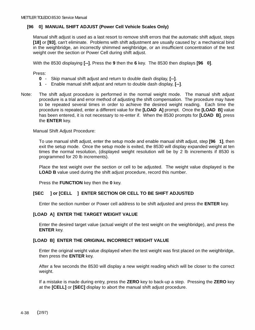
METTLER TOLEDO 8530 Service Manual
(2/97)4-38
[96 0] MANUAL SHIFT ADJUST (Power Cell Vehicle Scales Only)
Manual shift adjust is used as a last resort to remove shift errors that the automatic shift adjust, steps[18] or [93], can't eliminate. Problems with shift adjustment are usually caused by: a mechanical bindin the weighbridge, an incorrectly shimmed weighbridge, or an insufficient concentration of the testweight over the section or Power Cell during shift adjust.
With the 8530 displaying [--], Press the 9 then the 6 key. The 8530 then displays [96 0].
Press:0 - Skip manual shift adjust and return to double dash display, [--].1 - Enable manual shift adjust and return to double dash display, [--].
Note: The shift adjust procedure is performed in the normal weight mode. The manual shift adjustprocedure is a trial and error method of adjusting the shift compensation. The procedure may haveto be repeated several times in order to achieve the desired weight reading. Each time theprocedure is repeated, enter a different value for the [LOAD A] prompt. Once the [LOAD B] valuehas been entered, it is not necessary to re-enter if. When the 8530 prompts for [LOAD B], pressthe ENTER key.
Manual Shift Adjust Procedure:
To use manual shift adjust, enter the setup mode and enable manual shift adjust, step [96 1], thenexit the setup mode. Once the setup mode is exited, the 8530 will display expanded weight at tentimes the normal resolution, (displayed weight resolution will be by 2 lb increments if 8530 isprogrammed for 20 lb increments).
Place the test weight over the section or cell to be adjusted. The weight value displayed is theLOAD B value used during the shift adjust procedure, record this number.
Press the FUNCTION key then the 0 key.
[SEC ] or [CELL ] ENTER SECTION OR CELL TO BE SHIFT ADJUSTED
Enter the section number or Power cell address to be shift adjusted and press the ENTER key.
[LOAD A] ENTER THE TARGET WEIGHT VALUE
Enter the desired target value (actual weight of the test weight on the weighbridge), and press theENTER key.
[LOAD B] ENTER THE ORIGINAL INCORRECT WEIGHT VALUE
Enter the original weight value displayed when the test weight was first placed on the weighbridge,then press the ENTER key.
After a few seconds the 8530 will display a new weight reading which will be closer to the correctweight.
If a mistake is made during entry, press the ZERO key to back-up a step. Pressing the ZERO keyat the [CELL] or [SEC] display to abort the manual shift adjust procedure.

Chapter 4: INSTALLATION INSTRUCTIONS
(2/97) 4-39
Note: Manual shift adjust may not totally correct the shift error on the first attempt. If the displayedweight value is still out of tolerance after performing the manual shift adjust, repeat the manualshift adjust procedure until the weight reading is correct.
Once the shift adjustment is completed, enter the setup mode and disable manual shift adjustment,step [96 0]. The 8530 will then display [SA CAL]. Press the 1 key to permanently store the newshift constants. If you press the 0 key at this point the changes made with manual shift adjustmentare lost and the shift constants will revert back to their previous values.
After the manual shift adjust procedure is completed, it may be necessary to recalibrate the scaleas span or zero may have been affected. Verify that all sections weigh within tolerance and thenrecalibrate the scale using step [19] if necessary.
Manual Shift Adjust Example:
Displayed value with weight concentrated over section 1 is equal to 13458 lb. The target value(actual test weight value) is equal to 13500 lb, with a resulting error of 42 lb.
Press the FUNCTION key then the 0 key.
Enter 01 for section number followed by the ENTER key.After [LOAD A] is displayed, enter "13500", and press the ENTER key.
After [LOAD B] is displayed, enter "13458", and press the ENTER key.
The adjusted weight is now displayed. If the displayed weight did not reach the desired target valueof 13500, then repeat the procedure and enter a larger value for the [LOAD A] value. If thedisplayed weight is over the desired target value then repeat the procedure and enter a smaller[LOAD A] value.
[97 ] ACCESS SHORT CUT CALIBRATION DATA
This step provides direct access to the span, zero calibration coefficients. Power Cell vehicle scalesbases also permit access the shift adjust coefficients. In the event the 8530 Main PCB is replaced, the8530 can be recalibrated by entering the previously recorded short cut calibration data. SHIFT ADJUSTAND RECALIBRATION WITH TEST WEIGHTS IS NOT REQUIRED, if the short cut calibration datais entered into a replacement 8530 Main PCB.
With the 8530 displaying [--], Press the 9 then the 7 key. The 8530 then displays [97].
Press:0 - Skip Short Cut Calibration and return to double dash [--] display.1 - Access Short Cut Calibration Display and or Modify.
PRINT - Print Short Cut Calibration Values.
[97A ] DISPLAY SPAN VALUE[X.XXXXXX]
The span value is displayed. Enter a new value if desired. Press the ENTER key to accept thedisplayed value.
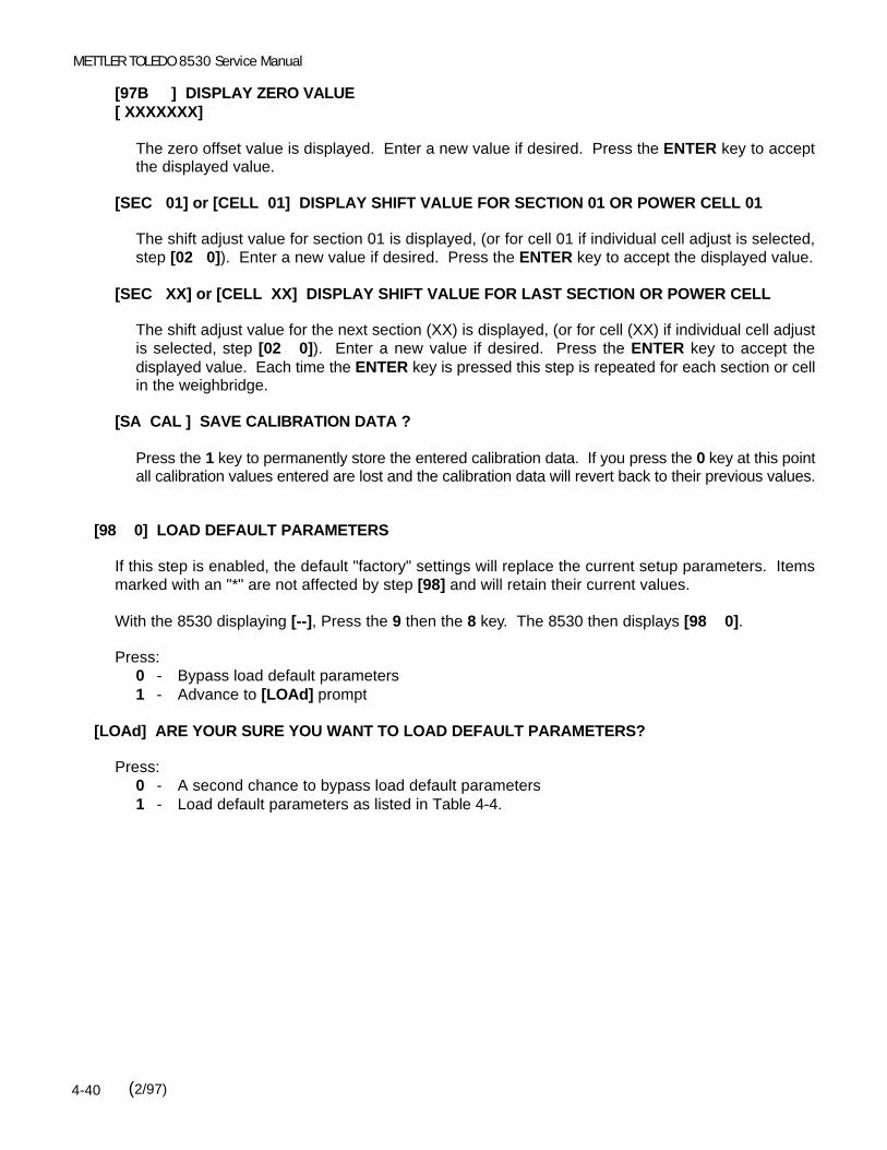
METTLER TOLEDO 8530 Service Manual
(2/97)4-40
[97B ] DISPLAY ZERO VALUE[ XXXXXXX]
The zero offset value is displayed. Enter a new value if desired. Press the ENTER key to acceptthe displayed value.
[SEC 01] or [CELL 01] DISPLAY SHIFT VALUE FOR SECTION 01 OR POWER CELL 01
The shift adjust value for section 01 is displayed, (or for cell 01 if individual cell adjust is selected,step [02 0]). Enter a new value if desired. Press the ENTER key to accept the displayed value.
[SEC XX] or [CELL XX] DISPLAY SHIFT VALUE FOR LAST SECTION OR POWER CELL
The shift adjust value for the next section (XX) is displayed, (or for cell (XX) if individual cell adjustis selected, step [02 0]). Enter a new value if desired. Press the ENTER key to accept thedisplayed value. Each time the ENTER key is pressed this step is repeated for each section or cellin the weighbridge.
[SA CAL ] SAVE CALIBRATION DATA ?
Press the 1 key to permanently store the entered calibration data. If you press the 0 key at this pointall calibration values entered are lost and the calibration data will revert back to their previous values.
[98 0] LOAD DEFAULT PARAMETERS
If this step is enabled, the default "factory" settings will replace the current setup parameters. Itemsmarked with an "*" are not affected by step [98] and will retain their current values.
With the 8530 displaying [--], Press the 9 then the 8 key. The 8530 then displays [98 0].
Press:0 - Bypass load default parameters1 - Advance to [LOAd] prompt
[LOAd] ARE YOUR SURE YOU WANT TO LOAD DEFAULT PARAMETERS?
Press:0 - A second chance to bypass load default parameters1 - Load default parameters as listed in Table 4-4.

Chapter 4: INSTALLATION INSTRUCTIONS
(2/97) 4-41
Default Parameters
Parameter Value Parameter Value Parameter Value
02030411131415161723
23A24
24A2526272829313233
*********3010244*0200
343536373841
41A4243444551
51A5253545556576162
0110010
960020100
48002012000
6364656667686971727374758182838485868788
0010021114***0*00000
Table 4-4 Load Default Parameters
Note: Items marked with a * are not effected by load default parameters, setup step [98].
[99 ] DISPLAY RAW COUNT OUTPUT OF INDIVIDUAL POWER CELLS
This step displays the raw count output of individual Power cells. Step [99] is used to verify that the8530 is communicating with individual Power cells and to determine that the Power cells have beenshimmed correctly. An error code is displayed if the 8530 is unable to communicate with the specifiedPower cell.
With the 8530 displaying [--], Press the 9 then the 9 key. The 8530 then displays [99 ].
Enter the address of the Power cell you wish to view (01 to 24) then press the ENTER key. The rawcount output of the cell is then displayed. Press the ENTER key to display the raw count output of thenext cell. Press the CLEAR key to return to the double dash [--] display. If a cell address of 00 isentered, the 8530 will return to the double dash [--] display.
Note: It is highly recommended that the raw count output of each cell be recorded after installation iscompleted. This data can be very useful troubleshooting information if a weighing problem occurslater.

METTLER TOLEDO 8530 Service Manual
(2/97)4-42
4.9 FINAL INSTALLATION INSTRUCTIONS
4.9.1 Record Setup Parameters
Once the 8530 has been configured and calibrated then it is important to record the raw count outputof the load cells at step [99], and either record or print out the calibration parameters. Save the rawcount outputs and calibration information for future use.
4.9.2 Remove the Setup Jumper
Remove the shorting block from the CAL jumper W5. Place the shorting block back onto one of the twopins of jumper W5.
4.9.3 Closing the Desk Enclosure
Carefully secure the front cover to the rear cover with the four screws in the corners of the rear cover. Be careful not to pinch the keyboard tail between the front and rear covers. DO NOT over tighten thecover screws when reinstalling them.
4.9.4 Sealing The NEMA 4X Wall Mount Enclosure
A small tube of sealant (*118251 00A) is included with the stainless steel wall mount enclosure versionof the 8530. This sealant MUST be applied to the cover gasket before final closure of the wall mountenclosure to ensure a water tight seal.
Clean the gasket, located on the inside of the door of the enclosure, with a clean cloth to remove anydebris. Apply an even bead of sealant to the gasket.
Smooth out the sealant with the tip of a finger so it is applied in an even, thin coat completely coveringthe gasket.
Close the door. Be careful to avoid pinching the keyboard extension harness between the enclosureand the door.
Snap each of the fasteners over the lip of the front cover. Tighten the wing type handle of each fastenerby turning 1800 clockwise. The lower right latch does not have a wing-type handle. Use an 11/16"wrench to tighten this latch.
Wipe off any excess sealant and snap the wing type handles down. Apply AC power to the indicator. The scale is now ready to use.
Clean the gasket, located on the inside of the door of the enclosure, with a clean cloth to remove anydebris.
4.9.5 Closing the Rack Enclosure
Replace the inner cover and the 3 inner cover retaining screws.
Slide the chassis back into the outer case.
Use caution when reinstalling the front panel screws to prevent cross threading. Do not overtighten thefront panel screws.

Chapter 5: OPERATING INSTRUCTIONS
(2/97) 5-1
Funct Zero lb kg Gross Net Tare
Weight
5. OPERATING INSTRUCTIONS5.1 DISPLAY
5.1.1 Display Description
The 8530 has a gray display lens with a seven digit, blue-green, seven segment, vacuumfluorescent display. Cursors are provided for function, zero, lb, kg, gross, net and tare.
Figure 5-1 Weight Display and Cursors
5.1.2 Display Cursors
Funct - The Function cursor illuminates to indicate that the FUNCTION key has been pressed.
Zero - The Zero cursor illuminates to indicate that the weight on the scale is within ±0.25increments of gross zero and that the 8530 is in the gross weight mode. If net zerocursor is enabled, step [88 1], then the zero cursor also indicates when the weight onthe weighbridge is within ±0.25 increments of gross or net zero.
lb - The lb cursor illuminates to indicate a that pound weight units are in use and that theweight on the scale is stable.
kg - The kg cursor illuminates to indicate that kilogram weight units are in use and that theweight on the scale is stable.
Gross - The Gross cursor illuminates to indicate that a gross weight value is being displayed.
Net - The Net cursor illuminates to indicate that a tare has been entered and that a net weightis being displayed.
Tare - The Tare cursor illuminates to indicate that a tare weight is being displayed. The tarecursor is illuminated when the displaying the stored tare value of a permanent register.

METTLER TOLEDO 8530 Service Manual
(2/97)5-2
5.2 KEYBOARD
Figure 5-2 Keyboard Layout
CLEAR - The CLEAR key is used to clear a tare weight and return to gross weight mode. TheCLEAR key also erases incorrect data entries and permits reentry of data.
ENTER - The ENTER key is used to terminate numeric data entry for consecutive numbering,time, date and setpoints.
ID - The ID key is used to enter a 12 digit numeric identification value.
GROSS/NET - The Gross/Net key is used to toggle between net and gross weight display. This keyhas no affect if the 8530 is in the gross weight mode.
Function - The Function key is used with the numeric keys to enter consecutive numbering, time,date, setpoint and accumulator data.
lb/kg - The lb/kg key toggles the 8530 between pound and kilogram weight units, if lb/kgswitching is enabled, step [82 1]. The increment size and decimal point of thedisplayed weight are adjusted to the nearest equivalent when switching between units. For example: 1 lb increment size changes to 0.5 kg, 2 lb increment size changes to1 kg, 5 lb increment size changes to 2 kg, etc.
MEMORY - The MEMORY key is used to access the 10 stored tare weight memories.
Numeric - The numeric keys are used to enter numeric data for tare, ID, time, date,Digits (0-9) setpoints, special functions, and other numeric entries.
PRINT - The PRINT key is used to request a demand mode output. If the weight on the scaleis unstable when a print request occurs the print request is saved and a data is outputwhen the weight on the scale is stable.
TARE - The TARE key is used to request the 8530 take an autotare. The 8530 will not take anautotare if the weight on the scale is unstable or at gross zero. The TARE key is alsoused to terminate a keyboard (numeric) tare entry. The least significant digit (LSD) ofa keyboard tare entry must correspond to the displayed increment size of the 8530 orelse the tare value entered is not accepted. If tare interlocks are enabled, step [32 1],then a keyboard tare can only be entered at gross zero.
ZERO - ZERO captures a new center of zero reference. The weight on the scale must be stableand within the pushbutton zero range (either ±2% or ±20% of the full scale capacity, asselected in setup step [25]) for a zero reference to be captured.

Chapter 5: OPERATING INSTRUCTIONS
(2/97) 5-3
5.3 POWERUP SEQUENCEThe 8530 performs internal self tests on all internal memory devices, display drivers and load cellcommunication during the power up procedure. At powerup the 8530 displays the following promptsin the order listed.
- The top segments of all seven display digits are illuminated for one second.
- The software part number, [128831 ] is displayed for a second.
- The revision level of the software is displayed for a second. For example: [L09 ] is the revisionlevel displayed for the 9th revised version of the software.
- All segments of all seven display digits [8888888] are illuminated for a second.
- All cursors are illuminated.
- All decimal points are illuminated.
- The 8530 will display [ E E E ] or [-E E E ] while attempting to capture zero. Once zero issuccessfully captured the 8530 displays weight. If autozero capture and tare interlocks aredisabled, the 8530 will display the current weight without attempting to capture zero.
Note: Zero MUST be captured after powerup before a demand mode data output can occur or beforelb/kg switching can occur. This requirement is not eliminated by disabling autozero capture ortare interlocks.
5.4 FUNCTION KEY DESCRIPTIONSSeveral of the 8530's special features are accessed by means of pressing the FUNCTION key followedby one of the numeric keys. Refer to Table 5-1.
Keys DescriptionFUNCTION 0 Access Manual Shift AdjustFUNCTION 1 Access Setpoint 1 (6 digits max)FUNCTION 2 Access Setpoint 2 (6 digits max)FUNCTION 3 Access Setpoint 3 (6 digits max)FUNCTION 4 Access Setpoint 4 (6 digits max)FUNCTION 5 Enter Consecutive NumberingFUNCTION 6 Enter Time (HHMMSS)FUNCTION 7 Enter Date (DDMMYY)FUNCTION 8 Access Subtotal and Total Accumulators
Table 5-1 Function Key Definitions

METTLER TOLEDO 8530 Service Manual
(2/97)5-4
5.4.1 FUNCTION 0 - Manual Shift Adjust (Power Cell Vehicle Scales Only)
To access the manual shift adjust procedure, press the FUNCTION key and then the 0 key. Referto Section 4.2, setup step [96], for manual shift adjust procedure description.
5.4.2 FUNCTION 1 THROUGH FUNCTION 4 - Display/Change Setpoint Data
To display the setpoint value, press the FUNCTION key and then the number of the setpoint to bedisplayed, (1 through 4). The 8530 will then display the current value of the setpoint for fiveseconds. Setpoint functions are only accessible if setpoints are enabled, setup step [36 2].
To change the displayed setpoint value, enter a new setpoint value while the 8530 is displaying thecurrent setpoint value. Press the ENTER key to accept the displayed setpoint value and return tothe weight display mode.
Note: The least significant digit of the setpoint value entered must match the displayed increment sizeselected in setup. If the setpoint value entered does not match the increment size then thesetpoint entry is ignored.
5.4.3 FUNCTION 5 - Display/Change Consecutive Numbering (CN)
To display the consecutive numbering counter, press the FUNCTION key and then the 5 key. The8530 will then display the current CN value for five seconds.
To change the displayed consecutive numbering value, enter a new CN value while the 8530 isdisplaying the current CN value. Press the ENTER key to accept the displayed CN value and returnto the weight display mode.
5.4.4 FUNCTION 6 - Display/Set Time
To display the current time, press the FUNCTION key and then the 6 key. The 8530 will then displaythe current time for five seconds.
To change the time, enter a new time while the 8530 is displaying the current time. Time is enteredin a 24 hour format including seconds, "HHMMSS". For example: 2:35 PM would be entered as"143500". Press the ENTER key to accept the displayed time and return to the weight displaymode.
5.4.5 FUNCTION 7 - Display/Change Date
To display the current date, press the FUNCTION key and then the 7 key. The 8530 will then displaythe current date for five seconds.
To change the date, enter a new date while the 8530 is displaying the current date. Date is enteredin the format selected at setup step [73]. Press the ENTER key to accept the displayed date andreturn to the weight display mode.
5.4.6 FUNCTION 8 - Print/Clear Accumulators
The 8530 is equipped with two nine digit accumulators. One accumulator functions as a subtotalweight accumulator and the other functions as a total weight accumulator. The 8530 canaccumulate gross weight, net weight or displayed weight as selected in setup step [29]. Weightdata is accumulated every time a print request occurs.

Chapter 5: OPERATING INSTRUCTIONS
(2/97) 5-5
To access the subtotal and total accumulators, press the FUNCTION key and then the 8 key. The8530 will then display the prompt [ACC] to indicate you are accessing the accumulators.
With the 8530 displaying [ACC], press the PRINT key to print the contents of the subtotal and totalaccumulators. The subtotal accumulator is cleared when totals are printed. To clear the total andsubtotal accumulators, press the CLEAR key while the 8530 is displaying [ACC]. Both the subtotaland total accumulators are cleared.
5.5 SCALE MEMORYThe 8530 provides ten memory location that can be used for either permanent or temporary storedvehicle weights that can be recalled to complete a transaction and print a ticket with gross, tare andnet weight. The available memory locations are numbered 0 though 9. Tare memories must beenabled, setup step [37 1] to permit stored tare weight operation. Step [38] selects permanent orinbound/outbound stored tare mode.
To view a stored weight value, press the Memory key and then the memory location (0 through 9) thatthe tare weight is stored in. The 8530 will then display the current contents of the memory location forfive seconds and then return to the weigh mode. If you press the MEMORY key while the 8530 isdisplaying a tare memory then the 8530 will display the next tare memory.
5.5.1 Permanent Stored Tare Weight Operation, Setup Step [38 0]
Permanent stored tare weight registers are normally used when the user has a fleet of vehicles withknown empty (tare) weights and can use a fixed tare value. The loaded vehicle is driven on thescale, the tare weight is recalled by ID from memory and a ticket is printed.
Permanent stored tare weights can be entered either by manually entering the known empty weightof the vehicle using the keyboard or by storing the current weight on the scale.
5.5.1.1 Manually Entering a Tare Weight Into a Permanent Memory Location
To manually enter a known tare weight, into a permanent memory location perform the followingprocedure:
- Press the Memory key and then the memory location (0 through 9) that the tare weight is tobe stored into. The 8530 will then display the current contents of the memory location for fiveseconds.
- Enter the desired stored tare value using the numeric keys, while the 8530 is displaying thecurrent stored tare weight value. Press the Enter key to terminate the tare entry. The tarevalue entered will be held in memory until manually replaced or cleared.
Note: Manually entered permanent stored tare weights replace the current value stored in memory.

METTLER TOLEDO 8530 Service Manual
(2/97)5-6
5.5.1.2 Storing an Empty Truck Weight Into a Permanent Memory
To store the current weight on the scale into a permanent memory location, perform the followingprocedure:
- Drive the empty vehicle on the scale platform and verify the 8530 is in the gross mode.
- Press the Memory key and then the memory location (0 through 9) that the tare weight is tobe stored into. The 8530 will then display the current contents of the memory location for fiveseconds.
- Press the Enter key while the 8530 is displaying the contents of the memory location to storethe current weight into the memory location.
Note: This mode of tare entry can only be used with a memory location that is empty, displaying astored tare value of [000000] when recalled. If a nonzero tare weight value is displayed for thememory location selected then the contents of this memory location will have to be clearedbefore you can store the weight on the scale into this memory location. Refer to Section 5.5.1.4for instructions on how to clear a permanent memory location. Repeat the weight storingprocedure once the memory location has been cleared.
5.5.1.3 Retrieving a Permanent Stored Tare Weight from Memory
To retrieve a permanent stored tare weight from memory, perform the following procedure:
- Verify the 8530 is in the gross mode, then drive the loaded vehicle onto the scale platform.
- Press the Memory key and then the memory location (0 through 9) that the tare weight forthis vehicle is stored in. The 8530 will then display the current contents of the memorylocation for five seconds.
- Press the Tare key while the 8530 is displaying the contents of the memory location to recallthe stored weight into the tare weight register and display the difference between the weightcurrently on the scale and the stored tare weight as a net weight.
- Press the Print key to print a ticket. The weight value recalled from memory will have thememory location in parentheses printed after it. Refer to Figure 5-3.
62040 lb18060 lb TR (4)43980 lb NET
Figure 5-3 Example Ticket Printout of Tare Weight Recalled From Memory Location 4

Chapter 5: OPERATING INSTRUCTIONS
(2/97) 5-7
5.5.1.4 Clearing a Permanent Stored Tare Weight from Memory
To clear a permanent stored tare weight from memory, perform the following procedure:
- Press the Memory key and then the memory location (0 through 9) that is to be cleared. The8530 will then display the current contents of the memory location for five seconds.
- Press the Clear key while the 8530 is displaying the contents of the memory location to erasethe current contents of the memory location.
5.5.2 Inbound/Outbound Temporary Stored Weight Operations, Setup Step [38 1]
The inbound/outbound weighing mode is most commonly used with random, over the road haulersthat are delivering or picking up product. The vehicle is weighed twice, once inbound and onceoutbound. The inbound weight is stored in a temporary register. When the outbound vehicle isweighed, the stored inbound weight is recalled from memory and used to calculate the net weightof the contents of the vehicle. Once an inbound stored tare weight is recalled the memory locationis cleared and is free to store a new inbound weight.
Net sign correction permits a temporary memory register to be used for both shipping and receiving. If net sign correction is enabled, setup step [64 1], then the stored inbound weight can be eitherthe full or the empty weight of the vehicle. When the inbound weight is recalled from memory, the8530 will automatically select the larger of the two weights (current weight on the scale or theinbound weight recalled from memory) as the gross weight. The smaller weight becomes the tareweight and the difference between the two is a positive net weight.
5.5.2.1 Storing an Inbound Vehicle Weights
To store the current weight on the scale into an temporary memory location, perform thefollowing procedure:
- Drive the inbound vehicle on the scale platform and verify the 8530 is in the gross mode.
- Press the Memory key and then the Print key. The 8530 will store the current weight on thescale into the next available memory location (0 through 9) and print the inbound weight withthe memory location in parentheses printed after it. Refer to Figure 5-4.
12540 lb (1)
Figure 5-4 Example Inbound Ticket Printout of Inbound Weight Stored in Memory Location 1
Note: If all ten memory locations are already full and the operator attempts to store an additionalinbound weight the 8530 will display [ FLL ] to indicate that no more inbound weights can beentered into memory until memory locations are emptied.

METTLER TOLEDO 8530 Service Manual
(2/97)5-8
5.5.2.2 Retrieving an Inbound Stored Vehicle Weight
To retrieve an inbound stored vehicle weight from memory, perform the following procedure:
- Verify the 8530 is in the gross mode, then drive the loaded vehicle (or unloaded vehicle if netsign correction is enabled) onto the scale platform.
- Press the Memory key and then the memory location (0 through 9) that the inbound weightfor this vehicle was stored in. The memory location (0 through 9) was printed in parenthesesafter the inbound weight, when the weight was stored. The 8530 will then display the currentcontents of the memory location for five seconds.
- Press the Tare key while the 8530 is displaying the contents of the memory location to recallthe stored weight into the tare weight register and display the difference between the weightcurrently on the scale and the stored tare weight as a net weight.
- Press the Print key to print a ticket. The weight value recalled from memory will have thememory location in parentheses printed after it. Refer to Figure 5-5.
62040 lb18060 lb TR (4)43980 lb NET
Figure 5-5 Example Ticket Printout of Tare Weight Recalled From Memory Location 4
Note: If net sign correction is enabled and the inbound weight was larger than the outbound weight thenthe 8530 will swap the gross and tare weight values on the printed ticket so that the larger weightis the gross weight and the smaller weight is the tare weight and difference between them isprinted as a positive net weight. Refer to Figures 5-6 and 5-7.
62040 lb (1)18060 lb TR43980 lb NET
-18060 lb 62040 lb TR (1)-43980 lb NET
Figures 5-6 and 5-7 Example Ticket Printouts with and without Net Sign Correction
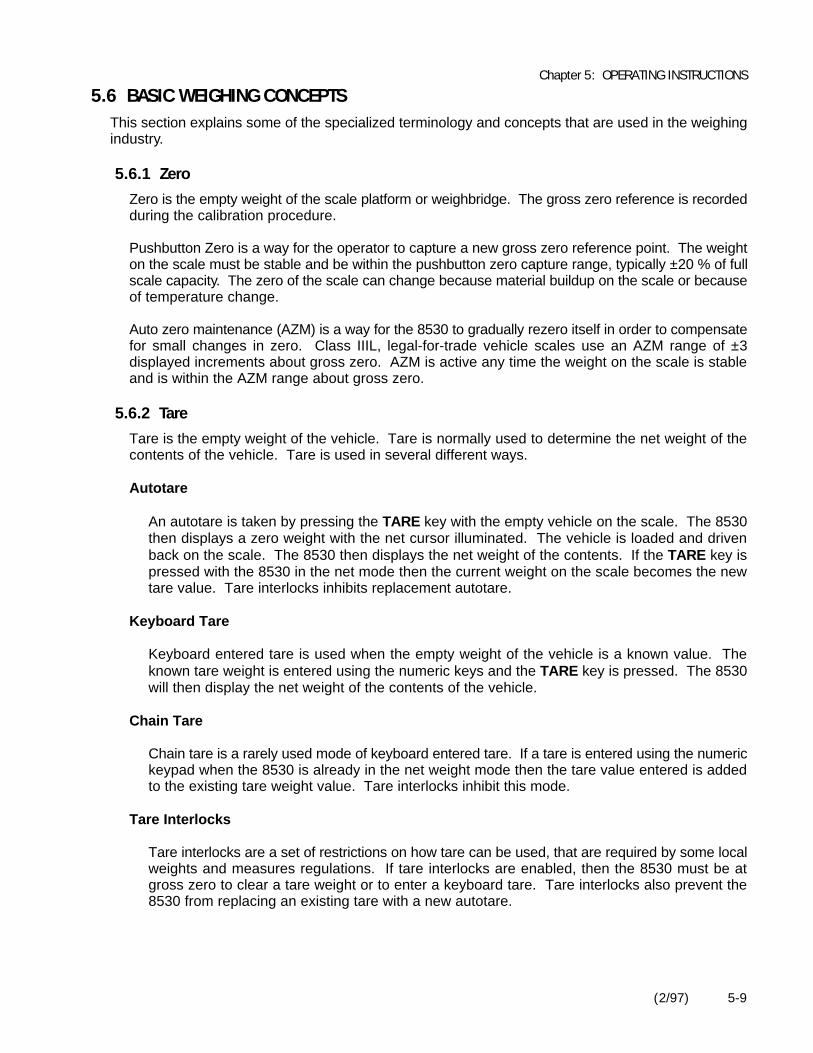
Chapter 5: OPERATING INSTRUCTIONS
(2/97) 5-9
5.6 BASIC WEIGHING CONCEPTSThis section explains some of the specialized terminology and concepts that are used in the weighingindustry.
5.6.1 Zero
Zero is the empty weight of the scale platform or weighbridge. The gross zero reference is recordedduring the calibration procedure.
Pushbutton Zero is a way for the operator to capture a new gross zero reference point. The weighton the scale must be stable and be within the pushbutton zero capture range, typically ±20 % of fullscale capacity. The zero of the scale can change because material buildup on the scale or becauseof temperature change.
Auto zero maintenance (AZM) is a way for the 8530 to gradually rezero itself in order to compensatefor small changes in zero. Class IIIL, legal-for-trade vehicle scales use an AZM range of ±3displayed increments about gross zero. AZM is active any time the weight on the scale is stableand is within the AZM range about gross zero.
5.6.2 Tare
Tare is the empty weight of the vehicle. Tare is normally used to determine the net weight of thecontents of the vehicle. Tare is used in several different ways.
Autotare
An autotare is taken by pressing the TARE key with the empty vehicle on the scale. The 8530then displays a zero weight with the net cursor illuminated. The vehicle is loaded and drivenback on the scale. The 8530 then displays the net weight of the contents. If the TARE key ispressed with the 8530 in the net mode then the current weight on the scale becomes the newtare value. Tare interlocks inhibits replacement autotare.
Keyboard Tare
Keyboard entered tare is used when the empty weight of the vehicle is a known value. Theknown tare weight is entered using the numeric keys and the TARE key is pressed. The 8530will then display the net weight of the contents of the vehicle.
Chain Tare
Chain tare is a rarely used mode of keyboard entered tare. If a tare is entered using the numerickeypad when the 8530 is already in the net weight mode then the tare value entered is addedto the existing tare weight value. Tare interlocks inhibit this mode.
Tare Interlocks
Tare interlocks are a set of restrictions on how tare can be used, that are required by some localweights and measures regulations. If tare interlocks are enabled, then the 8530 must be atgross zero to clear a tare weight or to enter a keyboard tare. Tare interlocks also prevent the8530 from replacing an existing tare with a new autotare.

METTLER TOLEDO 8530 Service Manual
(2/97)5-10
5.6.3 Sections
Vehicle scale weighbridges are normally divided up into what are called "sectional pairs" or sections. A section is a pair of load cells that are side by side in the weighbridge. For example the two loadcells that are at one end of the scale make up a section. Refer to Figure 5-8. Sections are primarilya consideration when dealing with shift errors.
Section 1 Section 2 Section 3 Section 4 Section 5
1
2
3
4
5
6
7 9
8 10
Figure 5-8 Load Cells and Sections in a Typical Vehicle Scale
5.6.4 Setpoints
Setpoints are on/off outputs that indicate whether the displayed weight on the scale is greater thanor less than a preprogrammed weight value. Setpoints are typically used in material fillingapplications in order to fill a vehicle to a preset weight. The 8530 provides 4, single speed, setpointcapability. The 8530 does not provide discrete electrical outputs. The setpoint information is codedinto the continuous serial data output. In order to use the 8530 setpoint capabilities an additionalpiece of equipment that understands the continuous format data output is required. The METTLERTOLEDO Models 3015 Filing controller and the Model 9215 Batching controller are examples ofdevices that understand the continuous format data output and can convert the setpoint data intohigh level on/off outputs designed to control material feeders.
5.6.5 Inbound/Outbound Weighing
Vehicle scales are often used in an inbound/outbound mode of operation where the vehicle isloaded or unloaded at the users site. In the inbound/outbound mode the vehicle empty (tare) weightis not known so the vehicle must be weighed twice, once empty and once loaded. In the past thiswas normally done by printing the inbound weight, printing the outbound weight and then handcalculating the difference or net weight.
The 8530 simplifies inbound/outbound weighing by permitting the operator to store the inboundvehicle weight in memory and then recalling that weight at a later time. Once the inbound weightis recalled, the 8530 calculates the net weight and prints an outbound ticket.
5.6.6 Net Sign Correction
Net sign correction is a feature that permits the 8530 to be used for both shipping (inbound empty)and receiving (inbound loaded) operations. If net sign correction is enabled, the 8530 will swap thegross and tare weight field on the printed ticket, if necessary, so that larger weight is the grossweight, the smaller weight is the tare weight, and the difference is always a positive net weight.
5.6.7 One Pass Weighing
One pass weighing is a mode where the user has a fleet of vehicles with known empty (tare) weight. The tare weight is recalled by ID with the loaded vehicle on the scale.

Chapter 5: OPERATING INSTRUCTIONS
(2/97) 5-11
Low Range Capacity = Scale Capacity, Step [14] x Low Range Increment Size, Step [17]
High Range Increment Size, Step [15]
Mid Range Capacity = Scale Capacity, Step [14] x Mid Range Increment Size, Step [16]
High Range Increment Size, Step [15]
5.7 AUTORANGE OPERATIONRange switching occurs when the total number of displayed increments for a range is equal to thetotal number of displayed increments of the high range. Refer to following Autorange example, the8530 is programmed as follows:
[11 0] Calibrate in pounds[13 2] Dual range operation is selected.[14 ] [400000] Scale Capacity[15 ] [ 50] High Range Increment Size[17 ] [ 20] Low Range Increment Size
Refer to equations 5-1 and 5-2 to calculate the largest weight that can be displayed in the lowerranges. Refer to the indicator setup section of the weighbridge installation manual for the correctscale capacity, and minimum increment size selection.
Equation 5-1 Low Range Capacity Calculation
Equation 5-2 Mid Range Capacity Calculation
DisplayDisplayedIncrement
SizeRange Calculation Formula
ActiveWeightRange
LowIncrement
Range20 lb
Capacity X Low Increment ÷ High Increment =Low Increment Range
(400,000 X 20) ÷ 50 = 160,000 lb
0 lbto
160,000 lb
HighIncrement
Range50 lb From Top of the Low Increment Range to Capacity
160,050 lbto
400,000 lb
Table 5-3 Autorange Operation Example
Note: Autorange works on the displayed weight value. Once a tare is taken the net weight is displayedin the low increment size until the net weight exceeds the low increment range. If the gross, tareand net weight are not all in the same increment range then the total of the net and tare weightmay not exactly equal the gross weight. Example: A tare weight of 46,020 lb is taken. The netweight of the contents of the vehicle is 180,050 lb. The total of the tare and net weight is226,070 lb, which is an invalid increment size. The 8530 will use the valid increment size for thegross weight which in this case would be by 50 lb increments resulting in a printed gross weightof 226,100 lb. This value is the same gross weight that would be displayed if the tare weight wascleared.

Chapter 6: INTERFACING AND I/O CONNECTORS
(2/97) 6-1
6. INTERFACING AND I/O CONNECTORS6.1 MAIN PCB CONNECTIONS AND JUMPERS
Figure 6-1 Main PCB
Main PCB Jumpers
W1 - OE Jumper (IN) W4 - Comma Jumper (Out)(Out) = Period for Decimal Point(IN) = Comma for Decimal Point
W2 - EPROM Select Jumper (2-3) W5 - Cal Jumper (Out)(IN) = Access Setup Mode(OUT) = Normal Operation
W3 - Filament Jumper (IN) W6 - Receive Data Jumper (Out)(IN) = Select 20 mA RxD(OUT) = Select RS-232 RxD
Main PCB Connectors
J1 - JW Host Port J6 - KeyboardJ2 - JN Printer Port J7 - Multi DLCJ3 - Single DLC J8 - PowerJ4 - Keyboard/Barcode (Not Used) J9 - Remote DisplayJ5 - Data Bus (Not Used)

METTLER TOLEDO 8530 Service Manual
(2/97)6-2
6.2 ENCLOSURE CONNECTOR LOCATIONS6.2.1 Desk Enclosure (Rear View)
Figure 6-2: Desk Enclosure (Rear View)
J1 - Load CellJN - Printer PortJW - Optional Host Port
6.2.2 Wall Enclosure (Bottom View)
Figure 6-3: Wall Enclosure (Bottom View)
JW - Optional Host PortJN - Printer PortJ1 - Load Cell

Chapter 6: INTERFACING AND I/O CONNECTORS
(2/97) 6-3
6.2.3 Rack Enclosure (Rear View)
Figure 6-5: Rack Enclosure (Rear View)
J1 - Load CellJN - Printer PortJW - Optional Host Port
6.3 LOAD CELL INTERCONNECTThe 8530 is compatible with the DigiTOL® Power Cells used in the DigiTOL® TRUCKMATE andRAILMATE vehicle scales, Models 7260, 7531, 7541, 7560, 7565 and the 760 DC when the multiple DLCadapter harness is installed.
The 8530 is compatible with single DigiTOL® Load Cell bases such as the Models 1996, 1997, 2096, 2097,2196, 2197, the Model 2160 DigiTOL® Floor Scale and the digital j-box, when the single DLC adapterharness is installed.
The 8530 is shipped with the multiple DLC adapter harness installed and is ready to be used withDigiTOL® Vehicle scales. If the 8530 is to be used with a single DLC base, the Model 2160 DigiTOL®floor scale or the digital j-box then the multiple DLC adapter harness must be removed from the 8530and the single DLC adapter harness, part number 131612 00A, must be installed between the loadcell extension harness and connector J3 on the 8530 Main PCB. Refer to Section 4.3 for load celladapter harness installation instructions.
CAUTION!Single DLC scale bases, the Model 2160 Floor Scale and the digital j-box require the single DLCadapter harness be installed between the load cell extension harness and connector J3 on the8530 Main PCB or else damage to the load cell may result.
REMOVE AC POWER FROM THE 8530 AND WAIT A MINIMUM OF 30 SECONDS BEFORECONNECTING OR DISCONNECTING ANY HARNESSES FROM PCB'S OR LOAD CELLS OR ELSEDAMAGE MAY RESULT.
The 8530 uses two different types of load cell connectors. The desk and rack enclosures use a DE-9connector, the wall enclosure version uses a 10 pin twist lock connector. Refer to Section 6.3.1 forconnector termination information.

METTLER TOLEDO 8530 Service Manual
(2/97)6-4
6.3.1 Load Cell Connector Installation Instructions
For wall enclosure version mating load cell connector termination instructions refer to the load cellconnector installation instructions, PN 133528 00A, packed with the 8350.
Note: The wall enclosure load cell connector uses letters to identify pins instead of numbers.
For desk and rack enclosure versions load cell connector termination, refer to the following instructions:
- The J1 load cell connector has a key plug installed in pin 3. Refer to Figure 6-6 for key pin location. This key is installed to insure that an analog scale base cannot be plugged into this connector. Thiskey pin MUST NOT be removed. The mating DE-9-P connector, PN 117599 00B, included with the8530 has pin 3 removed. If a different connector is used it will be necessary to remove pin 3 of themating connector. To accomplish this, grab as much of the pin as possible with a pair of needle nosepliers and bend the pin back and forth until it breaks off. Verify that all adjacent pins are straight afteryou finish.
Figure 6-6 DigiTOL® Load Cell Connector
- Slide the snuggest fitting rubber grommet from the connector shell assembly (PN 125384 00A) overthe un-terminated end of load cell cable.
- Strip back about 1¼" of the cable jacket and push the braided shield back over the rubber grommet. Refer to Figure 6-7.
Figure 6-7 Cable Shield Termination
- Solder the load cell cable wires to the pins of the mating connector. Refer to Section 6.3.2 forvehicle scale Power Cell wiring information. Refer to Section 6.3.3 for single DLC cable wiringinformation.
- Remove the paper backing from the embossed copper tape, PN 154360001, and wrap the coppertape around the braided shield that was pushed back over the rubber grommet. Trim any excessbraided shield that extends past the edge of the copper tape.
- Install the connector shell, PN 125384 00A, onto the DE-9-P mating connector. The rubber grommetwill fit into a recess in the connector shell to provide strain relief for the cable wiring and groundtermination through the connector shell for the braided shield.

Chapter 6: INTERFACING AND I/O CONNECTORS
(2/97) 6-5
6.3.2 Vehicle Scale, Power Cell Home Run Cable Termination
Verify that the Multiple DLC adapter harness, part number 131613 00A, has been installed between theexternal load cell harness and the multi DLC connector J7 on the 8530 Main PCB. Refer to Figure 6-1for connector J7 location.
If the Single DLC harness, part number 131612 00A, is installed between the external load cell harnessand the single DLC connector J3 on the 8530 Main PCB then remove the single DLC load cell harnessand install the multi DLC harness between the external load cell harness and connector J7 on the 8530Main PCB as described in Section 4.3 of this manual.
The pinout of the J1 load cell connector, located on the rear of the desk and rack enclosure or on thebottom of the wall enclosure is as listed in Table 6-1. Refer to the weighbridge installation manual forweighbridge and home run cable wiring information.
J1 Pin # Function Color Code
123456789
ABCDEFGHJK
COM AGround
Not UsedCOM B
+24 VDCGroundGround
+24 VDC+24 VDCNot Used
YellowGreen
BlueWhiteBrownBlackRed
Orange
Table 6-1 J1, Vehicle Scale Power Cell Connector Termination
Note: The J1 connector for desk and rack enclosure versions uses pin numbers, the wall enclosure versionuses pin letters.
6.3.3 Single DigiTOL® Load Cell TerminationError! Bookmark not defined.
Verify that the Single DLC adapter harness, part number 131612 00A, has been installed between theexternal load cell harness and the single DLC connector J3 on the 8530 Main PCB. Refer to Figure 6-1for connector J3 location. Refer to Section 4.3 of this manual for Single DLC adapter harnessinstallation instructions.
The Single DLC interface of the 8530 provides a single DigiTOL® load cell interface to permit operationwith the Models 1996, 1997, 2096, 2097, 2196, 2197 DigiTOL® Bench and Portable scale bases, andthe Model 2157 Digital J-Box Floor Scale. The Models 1996, 2096, and 2196 bases include a 10'interface cable, part number 130115 00A. The Models 1997, 2097, and 2197 bases supply an integral10' cable. The 8530 single DLC input is compatible with up to four analog load cells when used with thedigital j-box. The maximum length for a DLC home run cable is 300', use cable part number 510624-370, ordered by the foot.

METTLER TOLEDO 8530 Service Manual
(2/97)6-6
DigiTOL® Single DLC Scale Base Connector
Model 8530 199620962196
199720972197
Model 2160Digital J-Box
J-1 Pin Color
Function
Pin Color TB-5
123456789
ABCDEFGHJK
Red
Key PinWhiteGreenYellowBlueBlack
RxD ANot UsedNot UsedRxD B+20 VDCTxD BGroundTxD ANot UsedNot Used
1
Not Used5678
Red
Not UsedGreenYellowBlueBlack
3
46251
Table 6-2 DigiTOL® Scale Base Interconnect
CAUTION!The white wire MUST NOT be connected to Model 1996, 1997, 2096, 2097, 2196 and 2197bases or damage to the DigiTOL® load cell and single DLC input may result!
6.3.3.1 Digital J-Box and Model 2160 Floor Scale Termination
Connect the open end of the digital load cell cable to terminal strip TB5 of the digital j-box as listedin Table 6-2. Refer to Figure 6-8 for terminal strip TB-5 location.
Figure 6-8 Digital J-Box PCB

Chapter 6: INTERFACING AND I/O CONNECTORS
(2/97) 6-7
The Model 2160 is shipped with the four analog load cells already connected to the digital j-box PCB. If usingthe digital j-box with Flexmount or Centerline load cells then connect from two to four analog load cells toTerminal strips TB1 through TB4 of the digital j-box PCB. If two load cells are used they must be connectedto terminal strips TB1 and TB2. If three load cells are used they must be connected to terminal strips TB1,TB2 and TB3. Refer to Table 6-3 for analog load cell cable wiring information.
Digital J-Box Analog Load Cell Connectors
Analog Load Cell Cable Color Code
Pin Number Function Six Wire Four WireWith Sense Jumpers
123456
- Excitation- Sense- Signal+ Signal+ Sense+ Excitation
BlueRedBlackGreenYellowWhite
����
����
Black
RedWhite
Green
Table 6-3 Digital J-Box Analog Load Cell Connectors (TB1, TB2, TB3, and TB4)
Note: Sense leads for six wire load cell cables are connected to terminal strip TB1 only. Disconnect andtape back the sense leads on all other six wire load cell cables. Four wire load cell cables willrequire a jumper wire connecting +Excitation to +Sense and a second jumper wire connecting -Excitation to -Sense at TB1.
Be sure to install a jumper wire between pins 3 and 4 of any unused analog load cell inputs.
6.4 JN SERIAL PORTThe 8530 JN serial port supplies 20 mA current loop (CL) and RS-232 interfaces for both input and outputof serial data in either demand or continuous format output. Serial data is formatted as either 7 data bits,1 parity bit and 1 stop bit or as 8 data bits, no parity bit and 1 stop bit. A selectable checksum characterensures integrity of the data transmission. Refer to Tables 6-4, 6-5 and 6-6 and Figures 6-9 and 6-10 forJN Port interconnect information. Refer to Section 8.2. for a list of available printer interface cables andmating connectors.
Note: Only one of the serial ports, JN or JW can be configured for demand mode output. Either or bothof the ports can be configured for continuous mode output.
Both the 20 mA CL and RS-232 interfaces output data simultaneously and are usable at the same time.This lets the 8530 to send data to two different devices at the same time.
Serial ASCII command characters for remote CLEAR, TARE, PRINT and ZERO are accepted into eitherthe RS-232 or the 20 mA CL interfaces. Only one of the interfaces, RS-232 or 20 mA CL can be used toreceive ASCII characters (selected by jumper W6 on the 8530 Main PCB.
The 20 mA CL input can also be configured as a momentary contact input to provide a remote PRINT,TARE or ZERO key input. This mode does not interfere with receiving ASCII control characters into theRS-232 port.

METTLER TOLEDO 8530 Service Manual
(2/97)6-8
6.4.1 JN Port Printer Interconnect
8530JN Port
SignalDescription
301307
88068860
8860WD
8844 88568865
23789
10132224
TxD RS-232CRxD RS-232CGND/-TxD 20 mA+RxD 20 mA+20 mA Supply-RxD 20 mA+20 mA Supply+TxD 20 mALogic Ground
6
7
111622
18
H
K
25
23
3
7
None Jumpers None 12-23 None J101(B-C) None
Table 6-4 JN Port Printer Interface Cable Interconnect
Printer Interface Cable Notes:
M The 8806/8860 pin numbers are for the 8806 printer and the desk version of the 8860 using the adapterplug supplied with the 8860. The 8860 WD pin letters are for the washdown version of the 8860 printer.
M The jumper shown between pins 12 and 23 must be installed in the 8806 end of the interface cable andremote print pulse input must be enabled, setup step [87 1], for the remote print button on the Model8806 printer to operate.
M The J101 jumper shown for the 8844 document printer is located on the serial interface PCB inside the8844 printer.
86148616
8623861793239325
9330 9360 *8530JN Port
SignalDescription
TB1 PN or PY TB2 TB2 CH 2 or 42378910132224
TxD RS-232CRxD RS-232C
Logic GND/-TxD 20 mA+RxD 20 mA
+20 mA Supply-RxD 20 mA
+20 mA Supply+TxD 20 mALogic Ground
2
31
8
10
8
9
4
2
9822
10
None Jumpers None None W2-20 mA None None
Table 6-5 JN Port Accessory Interface Cable Interconnect

Chapter 6: INTERFACING AND I/O CONNECTORS
(2/97) 6-9
Accessory Interface Cable Notes:
M The W2 jumper shown for the Model 8617 Scoreboard Display, the Model 9323 BCD Converter and theModel 9325 Analog Output Converter is located on the serial interface PCB inside the accessory.
M ASCII input must be enabled, setup step [86 1], and jumper W6 on the 8530 Main PCB must be (IN),shorting the pins together, for the 9330 remote ASCII 20 mA CL input to work.
M Recommended JN port connection to the 9360 is by 20 mA current loop. Channels 2 and 4 on the 9360provide 20 mA current loop interfaces.
8530 JN Port PC Compatible Computer
Pin Description DB-25-S DB-9-S237
TxD RS-232RxD RS-232Logic Ground
327
235
PC Interface Cable Jumpers
4 �� 5 �� 6 �� 8 ��20��
1 ��4 ��6 ��7 ��8 ��
Table 6-6 JN Port Computer Interface Cable Interconnect
PC Compatible Interface Cable Notes:
M The jumpers shown in table 6-6 are located in the computer end of the interface cable.
M ASCII input must be enabled, setup step [86 1], and jumper W6 on the 8530 Main PCB must be (OUT),not shorting the pins together, for bidirectional RS-232 communication between the 8530 and thecomputer to work.
Figure 6-9 Desk and Rack Enclosure DB-25 Serial Connector
Figure 6-10 Wall Enclosure 26 Pin Twist Lock Serial Connector

METTLER TOLEDO 8530 Service Manual
(2/97)6-10
6.4.2 Remote Contact Closure Input
The JN port 20 mA RxD input can be used for a remote contact closure input for the function selectedin setup step [87]. The contact closure input can be used as a remote PRINT, TARE or ZERO key ifconnected to a momentary contact pushbutton.
The remote pushbutton can be located up to 2000 feet from the 8530. Use a shielded, twisted pair, datacable and ground the shield of the cable to the shell of the DB-25 connector on the 8530 end of thecable. Figure 6-11 details the remote contact closure input wiring.
Figure 6-11 20 mA Remote Print Pushbutton
6.5 JW OPTION PORTThe optional JW port supplies RS-232 and RS-422/485 interfaces for both input and output of serial datain demand, continuous or host mode. Serial data is formatted with either 7 data bits, 1 parity bit and 1 stopbit or as 8 data bits, no parity bit and 1 stop bit. A selectable checksum character ensures integrity of thedata transmission.
Refer to Tables 6-7, 6-8, 6-9 and 6-10 and Figures 6-9 and 6-10 for JW Port interconnect information. Refer to Section 8.2. for a list of available interface cables and mating connectors.
Both the RS-232 and the RS-422 interfaces output demand or continuous data simultaneously and areusable at the same time. This lets the 8530 to send output data to two different devices at the same time.
Serial ASCII command characters for remote CLEAR, TARE, PRINT and ZERO are accepted into eitherthe RS-232 or the RS-422/485 interfaces. Only one of the interfaces RS-232 or RS-422 can be used toreceive ASCII characters.
The Host mode interface provides advanced computer interfacing capabilities to permit a remote computerto access weight, setpoint and status information from the 8530. Control bytes permit remote operationof the 8530 by the computer. Setpoint and tare weight data can be uploaded to the 8530.
The host mode uses the RS-232C interface for short distance (50' or less) single scale to computerinterfacing applications. The host mode can use the RS-422, 4 wire, full duplex interface for long distance(up to 4000') single scale to computer interfacing applications. The host mode can also use the RS-485,2 wire, half duplex interface to connect up to eight, 8530 indicators in a multidrop network to a single, RS-485 interface of a host computer. Both the single scale and multidrop host mode interfaces use the samecommunication protocol. The host mode will only operate with one of the interfaces at a time, either RS-232 or RS-422/485.
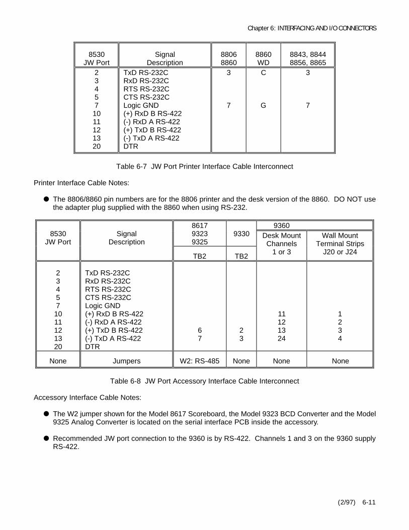
Chapter 6: INTERFACING AND I/O CONNECTORS
(2/97) 6-11
8530JW Port
SignalDescription
88068860
8860WD
8843, 88448856, 8865
234571011121320
TxD RS-232CRxD RS-232CRTS RS-232CCTS RS-232CLogic GND(+) RxD B RS-422(-) RxD A RS-422(+) TxD B RS-422(-) TxD A RS-422DTR
3
7
C
G
3
7
Table 6-7 JW Port Printer Interface Cable Interconnect
Printer Interface Cable Notes:
M The 8806/8860 pin numbers are for the 8806 printer and the desk version of the 8860. DO NOT usethe adapter plug supplied with the 8860 when using RS-232.
9360861793239325
93308530JW Port
SignalDescription
TB2 TB2
Desk MountChannels
1 or 3
Wall MountTerminal Strips
J20 or J24
234571011121320
TxD RS-232CRxD RS-232CRTS RS-232CCTS RS-232CLogic GND(+) RxD B RS-422(-) RxD A RS-422(+) TxD B RS-422(-) TxD A RS-422DTR
67
23
11121324
1234
None Jumpers W2: RS-485 None None None
Table 6-8 JW Port Accessory Interface Cable Interconnect
Accessory Interface Cable Notes:
M The W2 jumper shown for the Model 8617 Scoreboard, the Model 9323 BCD Converter and the Model9325 Analog Converter is located on the serial interface PCB inside the accessory.
M Recommended JW port connection to the 9360 is by RS-422. Channels 1 and 3 on the 9360 supplyRS-422.
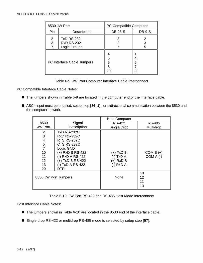
METTLER TOLEDO 8530 Service Manual
(2/97)6-12
8530 JW Port PC Compatible Computer
Pin Description DB-25-S DB-9-S
237
TxD RS-232RxD RS-232Logic Ground
327
235
PC Interface Cable Jumpers
4 �� 5 �� 6 �� 8 ��20��
1 ��4 ��6 ��7 ��8 ��
Table 6-9 JW Port Computer Interface Cable Interconnect
PC Compatible Interface Cable Notes:
M The jumpers shown in Table 6-9 are located in the computer end of the interface cable.
M ASCII input must be enabled, setup step [86 1], for bidirectional communication between the 8530 andthe computer to work.
Host Computer8530
JW PortSignal
DescriptionRS-422
Single DropRS-485
Multidrop23457
1011121320
TxD RS-232CRxD RS-232CRTS RS-232CCTS RS-232CLogic GND(+) RxD B RS-422(-) RxD A RS-422(+) TxD B RS-422(-) TxD A RS-422DTR
(+) TxD B(-) TxD A(+) RxD B(-) RxD A
COM B (+)COM A (-)
8530 JW Port Jumpers None10 ��12 ��11 ��13 ��
Table 6-10 JW Port RS-422 and RS-485 Host Mode Interconnect
Host Interface Cable Notes:
M The jumpers shown in Table 6-10 are located in the 8530 end of the interface cable.
M Single drop RS-422 or multidrop RS-485 mode is selected by setup step [57].

Chapter 6: INTERFACING AND I/O CONNECTORS
(2/97) 6-13
6.6 DEMAND MODE OUTPUTDemand mode output will occur any time a print request occurs either by pressing the Print pushbutton,an AutoPrint function, or a remote print command from either a remote print pushbutton, a host protocolcommand, or a single ASCII command character input from a host computer. The line format, baud rateand checksum are selectable in the setup mode.
Demand output is inhibited when the scale is "in motion", when the weight is under gross zero or overcapacity. If the demand output is inhibited because of motion or an over capacity or under zero conditionthen the print request will be stored and acted upon as soon as the 8530 is no longer inhibited to outputdata. Demand mode output can also be inhibited by minimum print and print interlock. Zero must becaptured at powerup before a demand mode output can occur.
6.6.1 Weight Field Format
6.6.6.1 Displayed Weight Format (Gross or Net)Gross Weight
DataSTX
SO
MSD
- - - - -LSD
SP Units
SI
CR
CKS
LF
Note A B C D E B F G H
Net Weight
DataSTX
SO
MSD
- - - - - -LSD
SP Units
SP N E T
SI
CR
CKS
LF
Note A B I D E D J B F G H
6.6.1.2 Single Line: Gross, Tare, Net
Single line gross weight format is output if no tare weight has been taken.
Single Line: Gross, Tare, Net
DataSTX
MSD
- - - - -LSD
SP Units
SP
MSD
- - - - -LSD
SP Units
Note A C D E D C D E
Single Line: Gross, Tare, Net (Continued)
DataSP T R
SP
SO
MSD
- - - - - -LSD
SP Units
SP N E T
SI
CR
CKS
LF
Note D J D B I D E D J B F G H
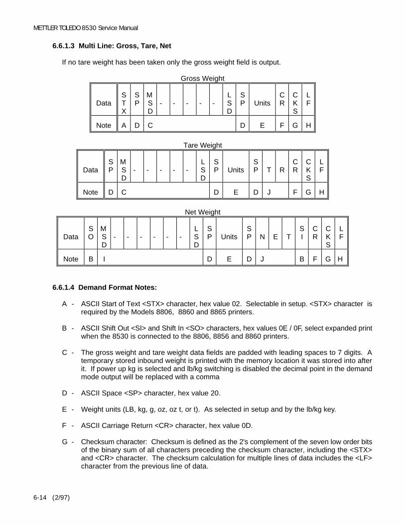
METTLER TOLEDO 8530 Service Manual
(2/97)6-14
6.6.1.3 Multi Line: Gross, Tare, Net
If no tare weight has been taken only the gross weight field is output.
Gross Weight
DataSTX
SP
MSD
- - - - -LSD
SP Units
CR
CKS
LF
Note A D C D E F G H
Tare Weight
DataSP
MSD
- - - - -LSD
SP Units
SP T R
CR
CKS
LF
Note D C D E D J F G H
Net Weight
DataSO
MSD
- - - - - -LSD
SP Units
SP N E T
SI
CR
CKS
LF
Note B I D E D J B F G H
6.6.1.4 Demand Format Notes:
A - ASCII Start of Text <STX> character, hex value 02. Selectable in setup. <STX> character isrequired by the Models 8806, 8860 and 8865 printers.
B - ASCII Shift Out <SI> and Shift In <SO> characters, hex values 0E / 0F, select expanded printwhen the 8530 is connected to the 8806, 8856 and 8860 printers.
C - The gross weight and tare weight data fields are padded with leading spaces to 7 digits. Atemporary stored inbound weight is printed with the memory location it was stored into afterit. If power up kg is selected and lb/kg switching is disabled the decimal point in the demandmode output will be replaced with a comma
D - ASCII Space <SP> character, hex value 20.
E - Weight units (LB, kg, g, oz, oz t, or t). As selected in setup and by the lb/kg key.
F - ASCII Carriage Return <CR> character, hex value 0D.
G - Checksum character: Checksum is defined as the 2's complement of the seven low order bitsof the binary sum of all characters preceding the checksum character, including the <STX>and <CR> character. The checksum calculation for multiple lines of data includes the <LF>character from the previous line of data.

Chapter 6: INTERFACING AND I/O CONNECTORS
(2/97) 6-15
H - ASCII Line Feed <LF> character, hex value 0A.
I - The net weight field is right justified and padded with spaces to 8 digits.
A negative net weight is indicated by a minus character before the most significant digit of theweight value. For example a weight of -5500 is printed with three leading spaces: SP
SP
SP-34.5
(SP = Space).
If bracketed printing is enabled, all truly measured weight values (instead of hand enteredvalues) are preceded by an ASCII < character and followed by an ASCII >.
If power up kg is selected and lb/kg switching is disabled the decimal point in the demandmode output will be replaced with a comma
J - Weight field descriptors. The TR and Net legends are printed after the tare and net weightfields to identify them, the gross weight field does not have a legend.
6.6.2 Time and Date Format
The time and date format is output as listed in Table 6-11. The abbreviations in Table 6-11 are definedas:
MM = monthDD = day of monthYY = yearsHH = hours
MM = minutesPM = AM or PMS
P = Space
Step [73] Selection Time and Date Format Clock Format
123456
MMSPDDS
PYYDD.MM.YYYYS
PMMSPDD
HH:MMSPPMS
PMMSPDDS
PYYDD.MM.YYS
PHH:MMYYS
PMMSPDDS
PHH:MM
NoneNoneNone12 Hour24 Hour24 Hour
Table 6-11 Time and Date Output Formats
6.6.3 Print Interlock
When print interlock is enabled, only one print per weighment is permitted. The weight on the scalemust return to a stable that is less than the minimum print value to reset the interlock. After theinterlock has reset, the weight on the scale must settle to a stable weight greater than minimum printvalue before another print can occur.
6.6.4 Autoprint
Autoprint enables the 8530 to automatically print a ticket when the weight on the scale settles to nomotion greater than the minimum print value. After an autoprint, the net weight on the scale must returnto a weight value less than the minimum print value to reset the autoprint feature. The PRINT key isdisabled when autoprint is enabled.
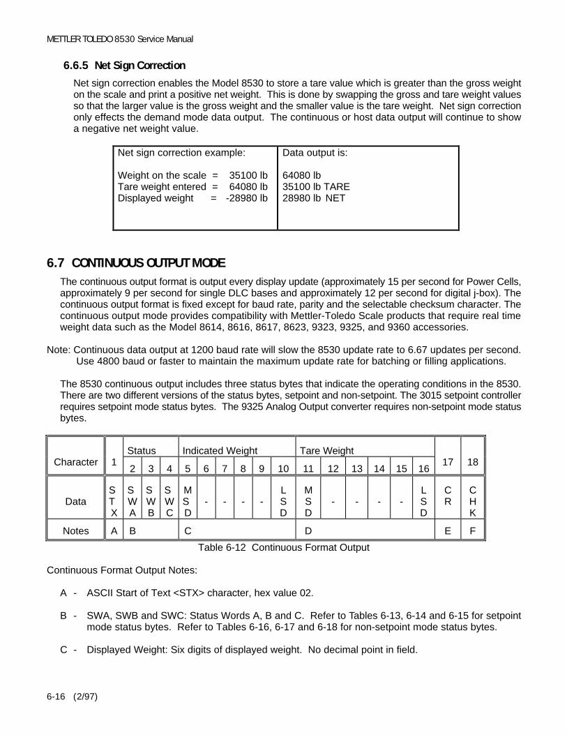
METTLER TOLEDO 8530 Service Manual
(2/97)6-16
6.6.5 Net Sign Correction
Net sign correction enables the Model 8530 to store a tare value which is greater than the gross weighton the scale and print a positive net weight. This is done by swapping the gross and tare weight valuesso that the larger value is the gross weight and the smaller value is the tare weight. Net sign correctiononly effects the demand mode data output. The continuous or host data output will continue to showa negative net weight value.
Net sign correction example:
Weight on the scale = 35100 lbTare weight entered = 64080 lbDisplayed weight = -28980 lb
Data output is:
64080 lb35100 lb TARE28980 lb NET
6.7 CONTINUOUS OUTPUT MODEThe continuous output format is output every display update (approximately 15 per second for Power Cells,approximately 9 per second for single DLC bases and approximately 12 per second for digital j-box). Thecontinuous output format is fixed except for baud rate, parity and the selectable checksum character. Thecontinuous output mode provides compatibility with Mettler-Toledo Scale products that require real timeweight data such as the Model 8614, 8616, 8617, 8623, 9323, 9325, and 9360 accessories.
Note: Continuous data output at 1200 baud rate will slow the 8530 update rate to 6.67 updates per second. Use 4800 baud or faster to maintain the maximum update rate for batching or filling applications.
The 8530 continuous output includes three status bytes that indicate the operating conditions in the 8530.There are two different versions of the status bytes, setpoint and non-setpoint. The 3015 setpoint controllerrequires setpoint mode status bytes. The 9325 Analog Output converter requires non-setpoint mode statusbytes.
Status Indicated Weight Tare WeightCharacter 1
2 3 4 5 6 7 8 9 10 11 12 13 14 15 1617 18
DataSTX
SWA
SWB
SWC
MSD
- - - -LSD
MSD
- - - -LSD
CR
CHK
Notes A B C D E F
Table 6-12 Continuous Format Output
Continuous Format Output Notes:
A - ASCII Start of Text <STX> character, hex value 02.
B - SWA, SWB and SWC: Status Words A, B and C. Refer to Tables 6-13, 6-14 and 6-15 for setpointmode status bytes. Refer to Tables 6-16, 6-17 and 6-18 for non-setpoint mode status bytes.
C - Displayed Weight: Six digits of displayed weight. No decimal point in field.

Chapter 6: INTERFACING AND I/O CONNECTORS
(2/97) 6-17
D - Tare Weight: Six digits of tare weight data. No decimal point in field.
E - ASCII carriage return <CR> character, hex value 0D.
F - Optional Checksum character. Checksum is defined as the 2's complement of the seven low orderbits of the binary sum of all characters preceding the checksum character, including the <STX> and<CR> character.
6.7.1 Status Byte Definition, Setpoint Mode [41A 0] or [51A 0]
BitFunction
DecimalPoint
Selection 2 1 0
DecimalPoint
orDummy
Zero
X00X0X
0.X0.0X
0.00X0.000X
0.0000X
00001111
00110011
01010101
Function Bit
Setpoint 1, Feeding = 0Setpoint 2, Feeding = 0Always a 1Setpoint 3, Feeding = 0
3456
Table 6-13 Status Word A Bit Definitions
Function Bit Function Bit
Gross/Net, Net = 1Under Zero, Negative = 1Overcapacity = 1Motion = 1lb/kg, kg = 1Always a 1Powerup Not Zeroed = 1
0123456
Always a 0Always a 0Always a 0Print Request = 1Setpoint 4, Feeding = 0Always a 1Hand Tare, Metric = 1
0123456
Table 6-14 Status Word B Bit Definitions Table 6-15 Status Word C Bit Definitions
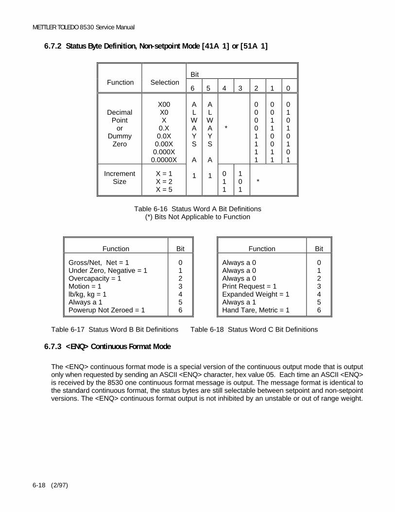
METTLER TOLEDO 8530 Service Manual
(2/97)6-18
6.7.2 Status Byte Definition, Non-setpoint Mode [41A 1] or [51A 1]
BitFunction Selection
6 5 4 3 2 1 0
DecimalPoint
orDummy
Zero
X00X0X
0.X0.0X
0.00X0.000X
0.0000X
*
00001111
00110011
01010101
IncrementSize
X = 1X = 2X = 5
ALWAYS
A
1
ALWAYS
A
1 011
101
*
Table 6-16 Status Word A Bit Definitions(*) Bits Not Applicable to Function
Function Bit Function Bit
Gross/Net, Net = 1Under Zero, Negative = 1Overcapacity = 1Motion = 1lb/kg, kg = 1Always a 1Powerup Not Zeroed = 1
0123456
Always a 0Always a 0Always a 0Print Request = 1Expanded Weight = 1Always a 1Hand Tare, Metric = 1
0123456
Table 6-17 Status Word B Bit Definitions Table 6-18 Status Word C Bit Definitions
6.7.3 <ENQ> Continuous Format Mode
The <ENQ> continuous format mode is a special version of the continuous output mode that is outputonly when requested by sending an ASCII <ENQ> character, hex value 05. Each time an ASCII <ENQ>is received by the 8530 one continuous format message is output. The message format is identical tothe standard continuous format, the status bytes are still selectable between setpoint and non-setpointversions. The <ENQ> continuous format output is not inhibited by an unstable or out of range weight.

Chapter 6: INTERFACING AND I/O CONNECTORS
(2/97) 6-19
6.8 HOST MODE INTERFACE PROTOCOLThe JW port never transmits without a command to do so from the host computer. The RS-485 interfaceprovides a master/satellite protocol to permit up to eight 8530's to be connected in a daisy chain networkto a single host device. Each 8530 is assigned a unique scale address in setup, from 2 to 9, to distinguishone 8530 from another. The RS-232 interface can be used to connect one 8530 to one computer usingthe same protocol as the multidrop interface.
There are 2 basic types of communication that occur between the host and the 8530.
Upload The host requests information from the 8530, and the 8530 responds to the request.Download The host transmits new data to the 8530.
The host interface mode has been enhanced with extended features to permit remote troubleshooting ofthe scale system. The original 8530 host mode is also available for compatibility with existing applications.
6.8.1 Host Mode Data Packet Format
All transmissions by the host or the 8530 are in the format shown in Table 6-19.
DataSTX
ADR
DIR
FCT
Data FieldCR
CHK
Notes A B C D E F G
Table 6-19 Host Interface Message Format
Host Interface Message Format Notes:
A - <STX> ASCII Start of Text Character, Hex 02.
B - <ADR> 8530 scale address selected in setup, valid addresses are from 2 to 9 (from 32 hex to 39hex).
C - <DIR> Data Direction, "U" = Upload (8530 to Host), "D" = Download (Host to 8530)
D - <FCT> Function code, refer to Function Code Table 6-20.
E - <Data Field> The data field is either the uploaded data from the 8530 or the downloaded datafrom the host. Not all function codes use the data field.
F - <CR> ASCII Carriage Return, hex value 0D.
G - <CKS> Optional Checksum Character. Checksum is defined as the 2's complement of the sevenlow order bits of the binary sum of all characters preceding the checksum character, including the<STX> and <CR> character.
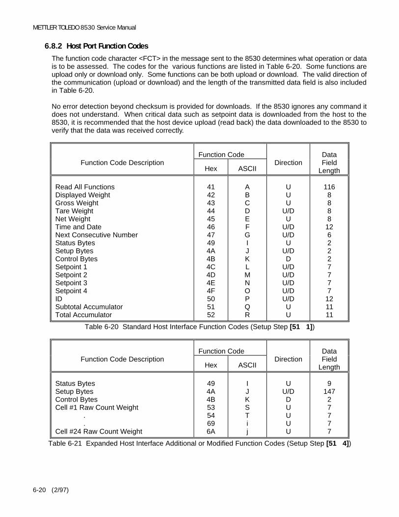
METTLER TOLEDO 8530 Service Manual
(2/97)6-20
6.8.2 Host Port Function Codes
The function code character <FCT> in the message sent to the 8530 determines what operation or datais to be assessed. The codes for the various functions are listed in Table 6-20. Some functions areupload only or download only. Some functions can be both upload or download. The valid direction ofthe communication (upload or download) and the length of the transmitted data field is also includedin Table 6-20.
No error detection beyond checksum is provided for downloads. If the 8530 ignores any command itdoes not understand. When critical data such as setpoint data is downloaded from the host to the8530, it is recommended that the host device upload (read back) the data downloaded to the 8530 toverify that the data was received correctly.
Function CodeFunction Code Description
Hex ASCIIDirection
DataField
Length
Read All FunctionsDisplayed WeightGross WeightTare WeightNet WeightTime and DateNext Consecutive NumberStatus BytesSetup BytesControl BytesSetpoint 1Setpoint 2Setpoint 3Setpoint 4IDSubtotal AccumulatorTotal Accumulator
41424344454647494A4B4C4D4E4F505152
ABCDEFGIJKLMNOPQR
UUU
U/DU
U/DU/DU
U/DD
U/DU/DU/DU/DU/DUU
1168888
1262227777
121111
Table 6-20 Standard Host Interface Function Codes (Setup Step [51 1])
Function CodeFunction Code Description
Hex ASCIIDirection
DataField
Length
Status BytesSetup BytesControl BytesCell #1 Raw Count Weight
.
.Cell #24 Raw Count Weight
494A4B5354696A
IJKSTij
UU/DDUUUU
914727777
Table 6-21 Expanded Host Interface Additional or Modified Function Codes (Setup Step [51 4])
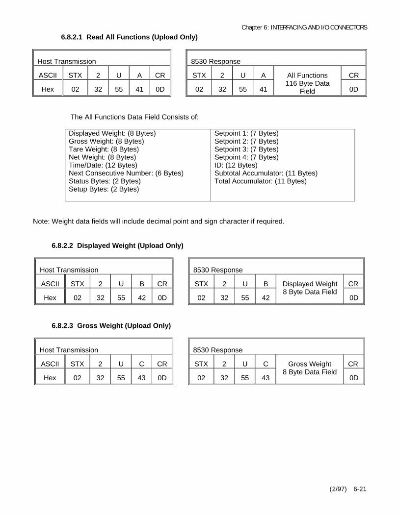
Chapter 6: INTERFACING AND I/O CONNECTORS
(2/97) 6-21
6.8.2.1 Read All Functions (Upload Only)
Host Transmission 8530 Response
ASCII STX 2 U A CR STX 2 U A CR
Hex 02 32 55 41 0D 02 32 55 41
All Functions116 Byte Data
Field 0D
The All Functions Data Field Consists of:
Displayed Weight: (8 Bytes)Gross Weight: (8 Bytes)Tare Weight: (8 Bytes)Net Weight: (8 Bytes)Time/Date: (12 Bytes)Next Consecutive Number: (6 Bytes)Status Bytes: (2 Bytes)Setup Bytes: (2 Bytes)
Setpoint 1: (7 Bytes)Setpoint 2: (7 Bytes)Setpoint 3: (7 Bytes)Setpoint 4: (7 Bytes)ID: (12 Bytes)Subtotal Accumulator: (11 Bytes)Total Accumulator: (11 Bytes)
Note: Weight data fields will include decimal point and sign character if required.
6.8.2.2 Displayed Weight (Upload Only)
Host Transmission 8530 Response
ASCII STX 2 U B CR STX 2 U B CR
Hex 02 32 55 42 0D 02 32 55 42
Displayed Weight8 Byte Data Field
0D
6.8.2.3 Gross Weight (Upload Only)
Host Transmission 8530 Response
ASCII STX 2 U C CR STX 2 U C CR
Hex 02 32 55 43 0D 02 32 55 43
Gross Weight8 Byte Data Field
0D
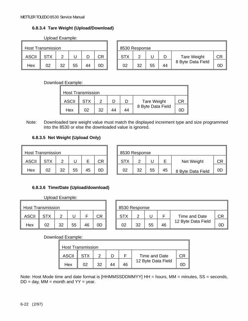
METTLER TOLEDO 8530 Service Manual
(2/97)6-22
6.8.3.4 Tare Weight (Upload/Download)
Upload Example:
Host Transmission 8530 Response
ASCII STX 2 U D CR STX 2 U D CR
Hex 02 32 55 44 0D 02 32 55 44
Tare Weight8 Byte Data Field
0D
Download Example:
Host Transmission
ASCII STX 2 D D CR
Hex 02 32 44 44
Tare Weight8 Byte Data Field
0D
Note: Downloaded tare weight value must match the displayed increment type and size programmedinto the 8530 or else the downloaded value is ignored.
6.8.3.5 Net Weight (Upload Only)
Host Transmission 8530 Response
ASCII STX 2 U E CR STX 2 U E CR
Hex 02 32 55 45 0D 02 32 55 45
Net Weight
8 Byte Data Field 0D
6.8.3.6 Time/Date (Upload/download)
Upload Example:
Host Transmission 8530 Response
ASCII STX 2 U F CR STX 2 U F CR
Hex 02 32 55 46 0D 02 32 55 46
Time and Date12 Byte Data Field
0D
Download Example:
Host Transmission
ASCII STX 2 D F CR
Hex 02 32 44 46
Time and Date12 Byte Data Field
0D
Note: Host Mode time and date format is [HHMMSSDDMMYY] HH = hours, MM = minutes, SS = seconds,DD = day, MM = month and YY = year.

Chapter 6: INTERFACING AND I/O CONNECTORS
(2/97) 6-23
6.8.3.7 Next Consecutive Number (Upload/Download)
Upload Example:
Host Transmission 8530 Response
ASCII STX 2 U G CR STX 2 U G CR
Hex 02 32 55 47 0D 02 32 55 47
Next ConsecutiveNumber
6 Byte Data Field 0D
Download Example:
Host Transmission
ASCII STX 2 D G CR
Hex 02 32 44 47
Next ConsecutiveNumber
6 Byte Data Field 0D
Note: Host command function code H (hex value 48) is not used with the 8530 host interface.
6.8.3.8 Status Bytes (Upload Only)
Status bytes 1 and 2 provide information about the operation of the 8530. In addition if the expandedhost mode is selected, setup step [51 4], setup bytes 3 through 9 include any displayed errorcodes.
Standard Host Mode Status Bytes:
Host Transmission 8530 Response
ASCII STX 2 U I CR STX 2 U I CR
Hex 02 32 55 49 0D 02 32 55 49
Status Bytes:2 or 9 bytes
0D
Function Bit Function Bit
Gross/Net, Net = 1Negative Weight = 1Overcapacity = 1Motion = 1lb/kg, kg = 1Always a 1Powerup Not Zeroed = 1
0123456
Setpoint 1 Feeding = 1Setpoint 2 Feeding = 1Setpoint 3 Feeding = 1Setpoint 4 Feeding = 1Print Request = 1Expanded Weight Display = 1Always = 1
0123456
Status Byte 1 Bit Definitions Status Byte 2 Bit Definitions
Status bytes 3 through 9 are used for displayed error codes. These bytes will be all spaces whenthe 8530 is in the normal weighing mode. If the 8530 is in an error condition displaying an error codethen these bytes will contain the ASCII characters that are displayed on the 8530. Refer to Section7.3.3 for error code descriptions.

METTLER TOLEDO 8530 Service Manual
(2/97)6-24
6.8.3.10 Setup Bytes (Upload/Download)
Setup bytes permits the host computer to change the demand mode output on the fly. if theexpanded host mode is selected, setup step [51 4], the status bytes will also include the numberof active Power Cells, span, zero and shift adjust calibration coefficients.
Upload Example:
Host Transmission 8530 Response
ASCII STX 2 U J CR STX 2 U J CR
Hex 02 32 55 4A 0D 02 32 55 4A
Setup Bytes2 or 147 Byte
Data Field 0D
Download Example:
Host Transmission
ASCII STX 2 D J CR
Hex 02 32 44 4A
Setup Bytes2 or 147 Byte
Data Field 0D
BitFunction Bit Function
1 0
Enable ID Autoclear = 1Print CN = 1Shift Adjust Sectional Pairs = 1 *Always a 0Always a 1
23456
Don't Print IDPrint ID Normal SizePrint ID Expanded Size
001
010
Setup Byte 1 Bit Definition
Note: (*) Bit 4 of setup byte #1 is determines shift adjust mode (individual cell adjust or sectional pairs) sameas setup step [02], if expanded host mode is selected, setup step [51 4].
Bit Bits Bits
6
Print FormatStep 74 Selection
5 4 3
Time and Data FormatStep 73 Selection
2 1 0
Always=1
12345678
00001111
00110011
01010101
0123456
0000111
0022001
0101010
Setup Byte 2 Bit Definition

Chapter 6: INTERFACING AND I/O CONNECTORS
(2/97) 6-25
The expanded host mode adds the number of Power Cells selected at setup step [03], and the span,zero and shift adjust calibration coefficients from setup step [97] to the setup byte command. Theadditional setup data fields are defined as follows:
Number of Power Cells: (2 Bytes)Span Multiplier: (8 Bytes)Zero Offset: (7 Bytes)Shift 1 Multiplier: (8 Bytes)Shift 2 Multiplier: (8 Bytes)Shift 3 Multiplier: (8 Bytes)Shift 4 Multiplier: (8 Bytes)Shift 5 Multiplier: (8 Bytes)Shift 6 Multiplier: (8 Bytes)Shift 7 Multiplier: (8 Bytes)
Shift 8 Multiplier: (8 Bytes)Shift 9 Multiplier: (8 Bytes)Shift 10 Multiplier: (8 Bytes)Shift 11 Multiplier: (8 Bytes)Shift 12 Multiplier: (8 Bytes)Shift 13 Multiplier: (8 Bytes)Shift 14 Multiplier: (8 Bytes)Shift 15 Multiplier: (8 Bytes)Shift 16 Multiplier: (8 Bytes)
Note: Span, zero and shift adjust calibration coefficients can only be downloaded when the 8530 is in thesetup mode, (displaying the double dash [--] prompt).
6.8.3.11 Control Bytes
Only 1 control byte function can be used at a time. If more than 1 control byte function is desiredthen repeat the control byte function once for each function required.
Download:Host Transmission
ASCII STX 2 D K CR
Hex 02 32 44 4B
CB1
CB2 0D
Function Bit Function Bit
Print Request = 1Switch to lb = 1Switch to kg = 1Clear tare = 1Autotare = 1Zero = 1Always a 1
0123456
Clear Accumulators = 1Reload Default Parameters = 1 *Always a 0Always a 0Always a 0Always a 0Always a 1
0123456
Control Byte 1 Bit Definitions Control Byte 2 Bit Definitions
Note: (*) Bit 1 of control byte #2 will reload default setup parameters only if expanded host mode isselected, setup step [51 4].
Control Byte 1 example:Print: A @ (41, 40 hex)Switch to lb: B @ (42, 40 hex)Switch to kg: D @ (44, 40 hex)Clear tare: H @ (48, 40 hex)
Control Byte 2 example:Autotare: P @ (50, 40 hex)Zero: ` @ (60, 40 hex)Clear Accumulators: @ A (40, 41 hex)Set Default Parameters: @ B (40, 42 hex)

METTLER TOLEDO 8530 Service Manual
(2/97)6-26
6.8.3.12 Setpoints 1, 2, 3 and 4 (Upload/Download)
The setpoint values for setpoints 1, 2, 3 or 4, are accessed individually by function codes "L", "M","N" or "P", (hex values 4C, 4D, 4E or 4F) for setpoints 1, 2, 3 or 4.
Upload Setpoint 1 Example:
Host Transmission 8530 Response
ASCII STX 2 U L CR STX 2 U L CR
Hex 02 32 55 4C 0D 02 32 55 4C
Setpoint 17 Byte
Data Field 0D
Download Setpoint 1 Example:
Host Transmission
ASCII STX 2 D L CR
Hex 02 32 44 4C
Setpoint 17 Byte
Data Field 0D
Note: Downloaded setpoint value must match the displayed increment type and size programmed into the8530 or else the downloaded value is ignored. It is highly recommended that you upload the setpointdata after a download to verify that the 8530 has accepted the downloaded setpoint value.
6.8.3.13 Numeric ID (Upload/Download)
Upload:
Host Transmission 8530 Response
ASCII STX 2 U P CR STX 2 U P CR
Hex 02 32 55 50 0D 02 32 55 50
ID12 Byte Field
0D
Download:
Host Transmission
ASCII STX 2 D P CR
Hex 02 32 44 50
ID12 Byte Field
0D
6.8.3.14 Subtotal Accumulator (Upload Only)
Host Transmission 8530 Response
ASCII STX 2 U Q CR STX 2 U Q CR
Hex 02 32 55 51 0D 02 32 55 51
SubtotalAccumulator11 Byte Field 0D

Chapter 6: INTERFACING AND I/O CONNECTORS
(2/97) 6-27
6.8.3.15 Total Accumulator (Upload Only)
Host Transmission 8530 Response
ASCII STX 2 U R CR STX 2 U R CR
Hex 02 32 55 52 0D 02 32 55 52
TotalAccumulator11 Byte Field 0D
6.8.3.16 Read Load Cell Raw Count Output (Upload Only)
The expanded host mode permits the host computer to read the raw count output of each of thePower Cells in a vehicle scale. If a load cell is in an error condition then the error code is outputinstead of the raw count. The raw count output of each load cell is accessed individually by meansof functions codes "S", "T", "U" ... "h", "i" or "j", (hex values 53, 54, 55 ... 68, 69 or 6A), for load celladdresses 1, 2, 3 ... 22, 23, or 24.
Verify the number of active load cells listed in setup bytes 3 and 4 before attempting to read the rawcount output of the load cells. The 8530 will respond with a raw count value of 0000000 if youattempt to read the raw count output of a cell that does not exist.
Read Cell #1 Raw Count Output Example:
Host Transmission 8530 Response
ASCII STX 2 U S CR STX 2 U S CR
Hex 02 32 55 53 0D 02 32 55 53
Cell 1 RawCount 7 Byte
Data Field 0D
Read Cell #10 Raw Count Output Example:
Host Transmission 8530 Response
ASCII STX 2 U \ CR STX 2 U \ CR
Hex 02 32 55 5C 0D 02 32 55 5C
Cell 10 RawCount 7 Byte
Data Field 0D
Note: If the load cell you are attempting to read raw count data from is in an error condition the error codefor that condition is sent instead of the raw count output. Refer to Section 7.3.3 for error codedescriptions.

Chapter 7: PREVENTIVE MAINTENANCE
(2/97) 7-1
7. PREVENTIVE MAINTENANCE
This section provides instructions and procedures for maintenance of the 8530, as well as atroubleshooting guide to aid in the correction of malfunctions.
7.1 REQUIRED TOOLS AND SUPPLIES
Volt-Ohm MeterMultiple DLC Simulator 0964-0033Single DLC Simulator 0917-0178
Soft, Lint Free, Cleaning ClothStatic Protection Bags for PCB'sStatic Wrist Strap
7.2 CLEANINGClean the keyboard and covers with a clean, soft cloth that has been dampened with a mild glass cleaner. Do not use any type of industrial solvent or the finish of the unit may be damaged. Do not spray cleanerdirectly onto the unit.
7.3 TROUBLESHOOTING PROCEDURESIf problems occur, record as much information as possible about the symptoms the scale is exhibitingbefore attempting to repair the scale. Perform the troubleshooting tests described next in the order listedto determine the cause of the malfunction. Always check power supply voltages before replacing anycomponents in the scale. If the 8530 is displaying an error code then record the error code and refer toSection 7.3.3.
7.3.1 AC Power and Ground Tests
Check the AC input power. The 8530 is rated to operate at an AC line voltage of 120 VAC +10%, -15%(102 to 130 VAC). Operation with line voltage outside this range may damage the 8530 Main PCB ortransformer. AC line voltages close to these minimum or maximum values indicate a marginal powersource that could cause unreliable operation.
Check for AC voltage between neutral and ground on the AC input. Neutral to ground voltages greaterthan 0.1 VAC indicate that the ground supplied to the 8530 is low quality. The 8530 requires a highquality, true earth ground for reliable operation. Neutral to ground voltage is an indication of the qualityof the power ground. Refer to the weighbridge installation manual for proper grounding procedures.
If the AC line voltage is incorrect or if there is excessive neutral to ground voltage then have a qualifiedelectrician correct the AC power. In cases of low or high line voltage a power line conditioner may berequired to correct the adverse power condition.
7.3.2 Cabling and External Equipment Tests
Visually inspect all interconnect cables for signs of damage. If an abraded or pinched cable is found,replace the damaged cable and retest the scale.
Disconnect all nonessential external equipment (printers, computers, remote displays, remote contactclosure input) and retest the scale. If the problem is corrected then try reconnecting the externalequipment, one piece at a time to determine the source of the problem.

METTLER TOLEDO 8530 Service Manual
(2/97)7-2
7.3.3 Error Codes
If an error code is displayed then record the error code, disconnect AC power to the 8530, wait 15seconds, then reconnect AC power. If this does not clear the error then perform the corrective measuresrecommended in Tables 7-1, 7-2 and 7-3.
If more than one corrective measure is listed for an error code then perform the corrective measuresin the order listed and retest between measures. Check the 8530 power supplies as described inSection 7.3.4 before replacing any parts. A malfunctioning 8530 Main PCB could be due to an incorrectpower supply voltage.
Error Error Description Corrective Measures
E1 Fatal Rom Error 1. Replace EPROM and Carrier.2. Replace Main PCB.
E2 Fatal Internal RAM Error 1. Replace Main PCB.
E3 Corrupt SETUP Memory Error 1. Enter setup and reprogram.2. Replace Main PCB.
E4 Fatal External RAM Error 1. Replace Main PCB.
E5 Display Verify Error 1. Replace Main PCB.
E6E7E8E9
E10E11E13
Load Cell Analog VerifyLoad Cell Data FormatLoad Cell no communicationLoad Cell out of range underLoad Cell RAM faultLoad Cell ROM faultLoad Cell NOVRAM fault
Refer to the appropriate Load Cell Error Table.Table 7-2 is for Vehicle Scale Power Cells.Table 7-3 is for Single DLC bases.
E14 Battery Backed Ram Memory Lost1. Replace Battery2. Check 8530 Power Supply Voltages.3. Replace Main PCB.
E16 Math Overflow Error 1. Enter setup and reprogram.2. Replace Main PCB.
E21 Incorrect scale capacity Press CLEAR key, then enter correct capacity.
E24 Illegal high range division Press CLEAR key, then enter correct division size.
E25 Illegal mid range division Press CLEAR key, then enter correct division size.
E26 Illegal low range division Press CLEAR key, then enter correct division size.
E27 Illegal Overcapacity Entry Press CLEAR key, enter legal overcapacity value.
E32 Insufficient Test WeightCalibration Error
1. Verify correct capacity has been entered.2. Use more test weight.
E34 Test weight larger than capacityCalibration Error
Press CLEAR key, test weight must be less than 105% ofcapacity. Verify correct capacity has been entered
E35 Incorrect Test Weight IncrementCalibration Error
Press CLEAR key, test weight value entered must matchthe increment size entered in setup.
Table 7-1 Error Codes

Chapter 7: PREVENTIVE MAINTENANCE
(2/97) 7-3
Error Error Description Corrective Measures
E36Insufficient Counts orBuild to small for load cell capacityCalibration Error
1. Press CLEAR key to clear.2. Check weighbridge for mechanical bind.3. Verify correct capacity and increment size has been entered.4. (Power Cell Scales Only)
4A. Verify shift adjust values at step [97] not = 0.0000004B. Check pit power supply voltages.
5. Recalibrate with larger test weight.6. Verify raw count cell output increases as load increases.7. Replace Main PCB.
E37 Calibration Data Checksum Error1. Recalibrate 8530.2. Check 8530 Power Supply Voltages.3. Replace Main PCB.
E50 Illegal Power Cell Command1. Verify AC power and ground.2. Check 8530 Power Supply Voltages.3. Replace Main PCB.
E E Eor
-E E EScale not zeroed
1. Press ZERO key.2. Check weighbridge for mechanical bind.3. Recalibrate scale.
Table 7-1 Error Codes Continued
Load cell errors are handled differently for Power Cells and single DLC scale bases. Power Cell errorscodes are followed by a two digit number to identify the Power Cell at fault. Table 7-2 describes PowerCell error codes.
The recommended corrective measures listed in Table 7-2, assume that the load cell cable for theeffected load cell cable and the pit power supply voltages are checked before any parts are replaced. Most load cell errors are caused by defective load cell cables.
Error Error Description Corrective Measures
E7 XX Data format error in Power Cell XX1. Recalibrate scale.2. Replace load cell.3. Replace Main PCB.
E8 XX No communication Power Cell XX 1. Refer to Sections 7.3.6 and 7.3.7.
E9 XX Power Cell XX out of range under 1. Check weighbridge for mechanical bind.4. Refer to Section 7.3.6.
E10 XX RAM fault in Power Cell XX1. Verify Eprom is L08 revision or higher.2. Replace Power Cell XX.3. Replace Main PCB.
E11 XX ROM fault in Power Cell XX 1. Replace Power Cell XX.2. Replace Main PCB.
E13 XX NOVRAM fault in Power Cell XX 1. Replace Power Cell XX.2. Replace Main PCB.
Table 7-2 Vehicle Scale Power Cell Error Codes

METTLER TOLEDO 8530 Service Manual
(2/97)7-4
Error Error Description Corrective Measures
E6 Single DLC Analog Verify
1. Recalibrate scale.2. Check load cell cable.3. Check 8530 Power Supply Voltages.4. Check 8530 Main PCB with Single DLC Simulator. 4A. If 8530 OK with DLC Simulator then replace load cell. 4B. If error with DLC Simulator, then replace 8530 Main PCB
E7 Single DLC Format Error
1. Check load cell cable.2. Check 8530 Power Supply Voltages.3. Check 8530 Main PCB with Single DLC Simulator. 3A. If 8530 OK with DLC Simulator then replace load cell. 3B. If error with DLC Simulator, then replace 8530 Main PCB
E8 No communication with Single DLC
1. Check load cell cable.2. Check 8530 Power Supply Voltages.3. Check 8530 Main PCB with Single DLC Simulator. 3A. If 8530 OK with DLC Simulator then replace load cell. 3B. If error with DLC Simulator, then replace 8530 Main PCB
E9 Single DLC out of range under
1. Check platform for mechanical bind.2. Check load cell cable.3. If Digital J-box verify valid increment size selection.4. Recalibrate scale5. Check 8530 Power Supply Voltages.6. Check 8530 Main PCB with Single DLC Simulator. 6A. If 8530 OK with DLC Simulator then replace load cell. 6B. If error with DLC Simulator, then replace 8530 Main PCB
E10 Single DLC RAM fault
1. Check load cell cable.2. Check 8530 Power Supply Voltages.3. Check 8530 Main PCB with Single DLC Simulator. 3A. If 8530 OK with DLC Simulator then replace load cell. 3B. If error with DLC Simulator, then replace 8530 Main PCB
E11 Single DLC ROM fault
1. Check load cell cable.2. Check 8530 Power Supply Voltages.3. Check 8530 Main PCB with Single DLC Simulator. 3A. If 8530 OK with DLC Simulator then replace load cell. 3B. If error with DLC Simulator, then replace 8530 Main PCB
E13 Single DLC NOVRAM fault
1. Check load cell cable.2. Check 8530 Power Supply Voltages.3. Check 8530 Main PCB with Single DLC Simulator. 3A. If 8530 OK with DLC Simulator then replace load cell. 3B. If error with DLC Simulator, then replace 8530 Main PCB
Table 7-3 Single DLC Error Codes
Note: The Digital J-box will display an E9 error after calibration if an increment size is selected that issmaller than the minimum increment size listed in Section 4.7.2 of this manual. If an invalidincrement size was selected then select a valid increment size and recalibrate the 8530.

Chapter 7: PREVENTIVE MAINTENANCE
(2/97) 7-5
7.3.4 Main PCB Voltage Checks
The transformer assembly provides AC and DC power supply voltages to the 8530 Main PCB. The8530 Main PCB converts the AC and DC power supply voltages from the transformer assembly into thepower supply voltages required for scale operation.
All DC voltages listed are measured with respect to logic ground, black meter lead connected to V1 onthe 8530 Main PCB. Refer to Table 7-4 and Figure 7-1. The Power Cell supply voltage is not regulatedand the value measured is determined by both the number of Power Cells in the weighbridge and theAC line voltage. The DC voltage values are based on a power AC line voltage of from 103 to 130 VAC.
Acceptable DC VoltageVoltage Description
Minimum Maximum
MaximumAC
Ripple
PlusMeterLead
Notes
+24 VDC Raw Supply +22 +17 VDC +28.5 VDC 0.2 VAC R41 1
+22 VDC Power Cell Supply +16.5 VDC +28 VDC 0.2 VAC V4 2
+18 VDC Single DLC Supply 17 VDC 21 VDC .05 VAC +C40 3
+5 VDC A +5 Logic Supply +4.75 VDC +5.25 VDC 0.01 VAC +C31 4
+5 VDC B +5 Logic Supply +4.75 VDC +5.25 VDC 0.01 VAC +C32 5
+12 VDC Raw +5 Supply+ RS-232 Supply
+9.5 VDC +14 VDC 0.2 VAC A1-Pin 14 6
-12 VDC - RS-232 Supply -10 VDC -14.5 VDC 0.2 VAC A1-Pin 1 7
-37 VDC Display Supply -33 VDC -38 VDC 0.02 VAC -CR26 8
Battery RAM Memory +2.4 VDC +3 VDC 0.02 VAC +Battery 9
COM A Power Cell Data Line +1.9 VDC +2.7 VDC N.A. V2
COM B Power Cell Data Line +1.9 VDC +2.7 VDC N.A. V310
Table 7-4 Main PCB DC Power Supply Voltage Checks
Main PCB DC Voltage Notes:1 - +24 VDC: Raw Power Cell supply voltage, measured at top end of resistor R41.2 - +22 VDC: Power Cell supply voltage, measured at left end of V4. The +22 volt supply is switched
off during cell addressing, setup steps [04], [91] and [92].3 - +18 VDC: Single DLC supply voltage, measured at positive (top) end of capacitor C40.4 - +5 VDC A: Regulated control logic supply, measured at positive end of capacitor C31.5 - +5 VDC B: Regulated display logic supply, measured at positive end of capacitor C32.6 - +12 VDC: + RS-232 and raw +5 VDC supply, measured at pin 14 of IC A1.7 - -12 VDC: - RS-232 Supply, measured at pin 1 of IC A1.8 - -37 VDC: Display voltage, measured at negative end of diode CR26.9 - Battery: Battery Backed RAM Memory, measured at positive terminal of battery with AC power
disconnected.10 - COM A and COM B: The Power Cell COM A and COM B data lines are toggling between ground
and +5 VDC approximately 375,000 times per second. The COM line will measure about 2.4 VDCwith the home run load cell cable disconnected from the J1 load cell connector the 8530 indicator. Replace the 8530 Main PCB if the COM voltages are incorrrect with the home run cabledisconnected.

METTLER TOLEDO 8530 Service Manual
(2/97)7-6
Figure 7-1 8530 Main PCB Test Points
7.3.5 Transformer Assembly Power Supply Tests
If any of the Main PCB DC voltages listed in Section 7.3.4 are missing or incorrect, or if the 8530 displayis totally blank, then check the AC transformer voltages.
The transformer assembly supplies three AC supply voltages and the raw +24 VDC Power Cell supplyto the 8530 Main PCB. All AC supply voltage checks are measured across the pins indicated in Table7-5 and Figures 7-2 and 7-3.
CAUTION!Do not apply AC power to the 8530 with the transformer assembly unplugged from theJ8 connector on the 8530 Main PCB. The 22,000 TF capacitor in the TransformerAssembly will be charged and will retain a charge after the AC power is disconnected.
If this situation occurs, measure the DC voltage across the 22,000 TF capacitor. Wait for thecharge on the capacitor to totally dissipate before plugging the Transformer Assembly backinto the J8 connector on the 8530 Main PCB.
Damage to the 8530 Main PCB could occur if the Transformer Assembly is plugged intothe J8 connector on the 8530 Main PCB while the 22,000 TTF capacitor is still charged.
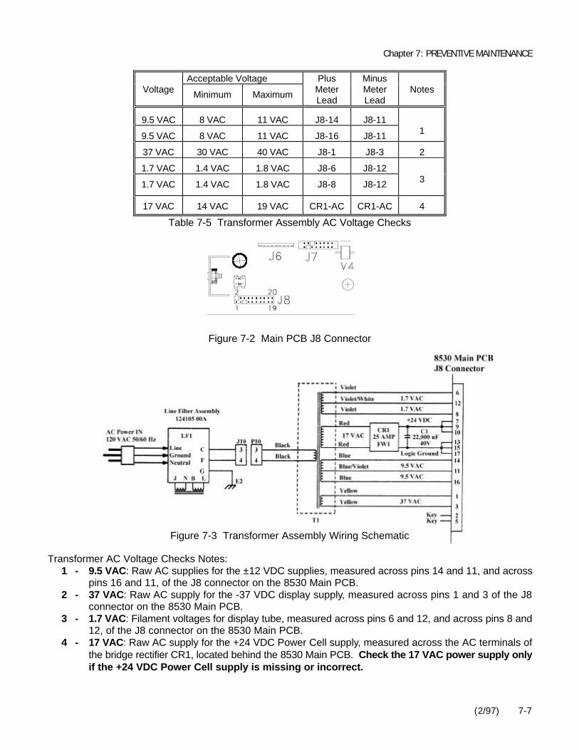
Chapter 7: PREVENTIVE MAINTENANCE
(2/97) 7-7
Acceptable VoltageVoltage Minimum Maximum
PlusMeterLead
MinusMeterLead
Notes
9.5 VAC 8 VAC 11 VAC J8-14 J8-11
9.5 VAC 8 VAC 11 VAC J8-16 J8-11 1
37 VAC 30 VAC 40 VAC J8-1 J8-3 2
1.7 VAC 1.4 VAC 1.8 VAC J8-6 J8-12
1.7 VAC 1.4 VAC 1.8 VAC J8-8 J8-12 3
17 VAC 14 VAC 19 VAC CR1-AC CR1-AC 4
Table 7-5 Transformer Assembly AC Voltage Checks
Figure 7-2 Main PCB J8 Connector
Figure 7-3 Transformer Assembly Wiring Schematic
Transformer AC Voltage Checks Notes:1 - 9.5 VAC: Raw AC supplies for the ±12 VDC supplies, measured across pins 14 and 11, and across
pins 16 and 11, of the J8 connector on the 8530 Main PCB.2 - 37 VAC: Raw AC supply for the -37 VDC display supply, measured across pins 1 and 3 of the J8
connector on the 8530 Main PCB.3 - 1.7 VAC: Filament voltages for display tube, measured across pins 6 and 12, and across pins 8 and
12, of the J8 connector on the 8530 Main PCB.4 - 17 VAC: Raw AC supply for the +24 VDC Power Cell supply, measured across the AC terminals of
the bridge rectifier CR1, located behind the 8530 Main PCB. Check the 17 VAC power supply onlyif the +24 VDC Power Cell supply is missing or incorrect.

METTLER TOLEDO 8530 Service Manual
(2/97)7-8
7.3.6 Power Cell Weighbridge Troubleshooting
There are two type of Power Cells used in DigiTOL® weighbridges, the NMOS Power Cell and theCMOS Power Cell. The CMOS Power Cell is a new type of cell that can operate directly from the +22VDC supply from the 8530 and does not require the Pit Power Supply PCB. The CMOS Power Cell canbe used to replace a NMOS Power Cell in an existing weighbridge and will operate with the Pit PowerSupply PCB. The NMOS Power Cell can not be used in CMOS weighbridges that do not have the PitPower Supply PCB.
The CMOS Power Cells can also be used with the Intrinsic Safety Barrier, Model Number 0917-0198in areas classified as Hazardous by the National Electrical Code (NEC) because of combustible orexplosive atmospheres. The 8530 indicator MUST be located in the nonhazardous are if used withthe CMOS Power Cell and the intrinsic safety barrier. Refer to the 0917-0198 CMOS Intrinsic SafetyBarrier installation instruction manual and the DigiTOL® Hazardous Area Wiring Diagram, TC100442,for troubleshooting information.
The 8530 communicates with the Power Cells using a master/satellite, two wire, half duplex, multi-dropcommunication protocol at 375,000 baud. The 8530 is the master and the Power Cells are satellitesthat transmit data only when the 8530 requests data. The COM A and COM B data lines from the 8530are wired in parallel, to all Power Cells. A shorted data line can result in [E8] error codes for some orall Power Cells in the weighbridge.
7.3.6.1 NMOS Weighbridges (Pit Power Supply PCB)
The home run cable from the 8530 terminates in the weighbridge at the Pit Power Supply PCB. ThePit Power Supply converts the +22 VDC Power Cell supply from the 8530 into the +18.5 VDC and+8.5 VDC power supplies required by NMOS Power Cells. The Pit Power Supply has connectionsfor six Power Cells. Weighbridges with more cells use the Pit Power Supply Expander PCB toprovide more Power Cell connections.
All DC voltages listed are measured with respect to logic ground, black meter lead connected to pin5 of Terminal strip J6 on the Pit Power Supply PCB. The +22 VDC Power Cell supply voltage is notregulated and the value measured is determined by both the number of Power Cells in theweighbridge the AC line voltage and the length of the home run cable. The DC voltage values arebased on a power AC line voltage of from 103 to 130 VAC. Refer to Table 7-6 and Figure 7-4 for testpoints.
Acceptable DC VoltageVoltage Description
Minimum Maximum
MaximumAC
Ripple
PlusMeterLead
Notes
+22 VDC Power Cell Supply +16 VDC +28 VDC 0.2 VAC J6-Pin 1
+8.5 VDC Cell Logic Supply +7.5 VDC +9 VDC 0.2 VAC J1-Pin 4
+18.5 VDC Cell Analog Supply +17 VDC +19 VDC 0.2 VAC J1-Pin 31
COM A Data Line +1.9 VDC +2.7 VDC N.A. J6-Pin 8
COM B Data Line +1.9 VDC +2.7 VDC N.A. J6-Pin 72
Chassis Ground Chassis Ground -1 VDC +1 VDC 1 VAC Ground Pad 3
Table 7-6 Pit Power Supply PCB Voltage Checks

Chapter 7: PREVENTIVE MAINTENANCE
(2/97) 7-9
Figure 7-4 Pit Power Supply PCB
Pit Power Supply Voltage Checks Notes:
1 The Pit Power Supply is short circuit protected, if the +8.5 or +18.5 VDC power supplies are shorted toground, the Pit Power Supply PCB will shut down to prevent damage. When the short is removed thepower supply voltage will come back. If the +8.5 or the +18.5 VDC power supply voltages are missing orvery low, disconnect all Power Cells and cell cables from the Pit Power Supply and retest. If the missingpower supply voltage is now ok, reconnect one Power Cell and cable at a time to find the fault.
2 The COM A and COM B data lines are toggling between ground and +5 VDC at 375,000 times per second. A voltmeter will measure the average voltage of the COM line which should be about 2.3 VDC. The actuallevel of the voltage measured is not critical, the important thing is that the COM lines are the same andare not high or low. If one of the COM lines is high or low, then disconnect all of the Power Cells and loadcell cables from the Pit Power Supply and measure the COM line voltages again. If the COM line voltagestested ok at the 8530 Main PCB but are bad with the Pit Power Supply connected then Pit Power Supplyis probably defective.
The Pit Power Supply includes surge voltage suppression devices on the power supply lines and on theCOM A and COM B data lines to protect the Power Cells and 8530 from lightning induced surge voltages. The surge suppression devices can fail by shorting to chassis ground. Testing the Pit Power Supply PCBrequires a digital multimeter that has a diode test setting.
A good Pit Power Supply will measure as an open circuit between the COM lines and chassis ground whenusing the diode test setting on you digital multimeter. Reverse the polarity of your meter leads and recheckbetween the COM lines to chassis ground, you should get the same open circuit reading. If the diode testsetting on your digital multimeter shows a measurable resistance between chassis ground and either ofthe COM A or COM B data lines, then the Pit Power Supply is defective.

METTLER TOLEDO 8530 Service Manual
(2/97)7-10
3 An excessive voltage between chassis ground and logic ground (greater than 1.5 volts) can cause aproblem with intermittent [E8] error codes. This condition is aggravated by connecting to the RS-232interface on either the JN or JW serial port. Voltage between chassis ground and logic ground is typicallycaused by leakage between the +18.5 VDC supply and chassis ground. Disconnect any externalequipment from the 8530 and disconnect all Power Cells and cell cables from the Pit Power Supply andretest. Reconnect one Power Cell and cable at a time to find the source of the chassis ground to logicground voltage.
7.3.6.2 CMOS Weighbridge (Nonhazardous Area Version Only)
CMOS Power Cell Weighbridges use a Connector PCB in place of the Pit Power Supply. The homerun cable from the 8530 terminates at terminal strip J8 of the Connector PCB. The Connector PCBhas terminations for six CMOS Power Cells. Weighbridges with more that six cells add a secondor third Connector PCB in a daisy chain fashion with terminal strip J1 of the first Connector PCBwired to terminal strip J8 on the next Connector PCB.
All DC voltages are measured with respect to logic ground, black meter lead connected to terminalstrip J2-GND on the Connector PCB. The DC voltage values listed in Table 7-7 are based on apower AC line voltage of from 103 to 130 VAC. Refer to Table 7-7 and Figure 7-5 for test points.
Acceptable DC VoltageVoltage Description
Minimum Maximum
MaximumAC
Ripple
PlusMeterLead
Notes
+22 VDCPower Cell Supplies:+VA, +VB and +VC +16 VDC +28 VDC 0.2 VAC
J2-VAJ3-VBJ4-VC
1
COM A Data Line +0.8 VDC +2.7 VDC N.A. J2-A
COM B Data Line +0.8 VDC +2.7 VDC N.A. J2-B2
Ground Chassis Ground -1 VDC +1 VDC 1 VAC J2-CGND 3
Table 7-7 Connector PCB Voltage Checks
Note: Intrinsically Safe versions use a reduced Power Cell supply voltage that will typically measurebetween 8.0 to 10.5 VDC.
Intrinsically Safe versions Power Cell COM A and COM B data line voltages will typically measure0.5 VDC with 6 Power Cells connected to a home run cable.

Chapter 7: PREVENTIVE MAINTENANCE
(2/97) 7-11
Figure 7-5 CMOS Power Cell Connector PCB Test Points
CMOS Power Cell Connector PCB Voltage Checks Notes:
1 The +22 VDC Power Cell Supply voltage is split into three, +22 VDC supply lines +VA, +VB and +VC. Each+22 VDC power supply is wired and measured independently.
2 The COM A and COM B data lines are toggling between ground and +5 VDC 375,000 times per second. The average DC voltage measured between the COM lines and ground for the CMOS Power cells varieswith the number of Power Cells in the system. COM line voltage will vary from 2.5VDC (with no cellsconnected) to 0.8 VDC, with 12 cells connected). The COM A and COM B voltage will drop with eachsuccessive load cell plugged into the system. The actual level of the voltage measured is not critical, theimportant thing is that the COM lines are close to the same value and are not high or low.
If one of the COM lines is high or low, then disconnect all of the Power Cells and load cell cables from theConnector PCB and measure the COM line voltages again. If the COM line voltages tested ok at the 8530Main PCB but are bad with the Connector PCB connected then Connector PCB is probably defective.
The Connector PCB includes surge voltage suppression devices on the power supply lines and on theCOM A and COM B data lines, to protect the Power Cells and 8530 from lightning induced surge voltages. The surge suppression devices can fail by shorting to chassis ground. To test the Connector PCBrequires a digital multimeter with a diode test setting. A good Connector PCB will measure as an opencircuit between the COM lines and chassis ground when using the diode test setting on you digitalmultimeter. Reverse the polarity of your meter leads and recheck between the COM lines to chassisground, you should get the same open circuit reading. If the diode test setting on your digital multimetershows a measurable resistance between chassis ground and either of the COM A or COM B data lines,then the Connector PCB is defective.
3 An excessive voltage between chassis ground and logic ground can cause a problem with intermittent [E8]error codes. This condition is aggravated by connecting to the RS-232 interface on either the JN or JWserial port. Voltage between chassis ground and logic ground is typically caused by leakage between the+22 VDC supply and chassis ground. Disconnect any external equipment from the 8530 and disconnectall Power Cells and cell cables from the Connector PCB and retest. Reconnect one Power Cell and cableat a time to find the source of the chassis ground to logic ground voltage.

METTLER TOLEDO 8530 Service Manual
(2/97)7-12
7.3.7 Troubleshooting Intermittent Power Cell [E8] Error Codes
A reoccurring problem with intermittent E8 error codes displayed on the 8530 display may result fromseveral different problems. Listed below are suggestions to assist you in eliminating intermittent E8error codes.
1 Visually inspect all load cell cables and load cell connectors for damage. Flex the load cell cablewhere the cable comes out of the load cell connector and observe the 8530 for errors. Any load cellcable that is bent very sharply at the load cell connector may be damaged internally. Verify that allload cell connectors are clean and greased and show no signs of corrosion. A damaged load cellcable may also result in intermittent [E9] error codes.
2 Verify that all cable wiring is tightly terminated at j-box terminal strips. Gently pull on individual wiresand tighten any loose terminal strip screws in the pit power supply and pit supply expanders. Checkfor corrosion on cable wiring.
3 For NMOS Power Cells check the +18.5 VDC, +8.5 VDC power supplies from the pit power supply. The pit power supply is short circuit protected and DC output voltages turn off automatically if ashort occurs. The output voltages turn back on automatically when the short is removed. For CMOSPower Cells check the +22 VDC power supply to the Connector PCB.
4 Disconnect ALL external equipment such as scoreboards, printers, computers, etc. from the 8530and determine if the intermittent E8 error codes are eliminated. Connection of the 8530communication ports to external equipment can result in intermittent E8 error codes. Data cablesrouted in the same conduit as AC power lines can cause erratic operation and [E8] error codes tobe displayed on the 8530. There is another possible problem with external equipment connectedto the 8530 by means of the RS-232 or RS-422/485 interfaces:
Most computers and printers connect logic ground to chassis ground. The 8530 is designed witha floating logic ground for increased protection from lightning damage. When the RS-232 interfaceof the 8530 is connected to a computer that connects logic ground to chassis ground this alsoconnects the logic ground of the 8530 to chassis ground. This logic ground to chassis groundconnection can cause intermittent "E8" errors in the 8530.
Caution: Connecting the logic ground of the 8530 to chassis ground will degrade the lightning immunity ofthe 8530.
If the RS-232 or RS-422/485 interfaces are the cause of the [E8] error codes or if there is a historyof lightning related damage, an optical isolator should be installed between the 8530 and the externaldevice. Contact technical support at 1-(800)-786-0040, for optical isolator recommendations for RS-232 or RS-422/485 interfacing. The JN Port 20 mA current loop interface is optically isolated anddoes not require additional isolation.
5 Measure between the COM A to ground and COM B to ground. The COM lines toggle between 0and +5 VDC. A typical DVM will read between 1.9 VDC and 2.7 VDC between a COM line andground for NMOS Power Cells (0.8 to 2.7 for CMOS Power Cells) when the 8530 and Power Cellsare communicating properly. If one of the COM lines is disconnected from the 8530, a commonsymptom is a constant [E8] error code for a particular cell which suddenly changes to a constant[E8] error code for a different cell.

Chapter 7: PREVENTIVE MAINTENANCE
(2/97) 7-13
If one of the COM lines is "dead" (sitting solid at a voltage near 0 VDC or +5 VDC) and is nottoggling, then the 8530 Main PCB may be defective. A "dead" COM line can also be caused by adamaged pit power supply, a shorted cell cable or a damaged cell. Try disconnecting part of thescale from the indicator (example: disconnect the expander PCB) and see if the "dead" COM linevoltage becomes active.
6 Check the +22 VDC supply from the 8530 at the pit power supply terminal strip TB6. If the +22 VDCsupply is below +16.5 VDC then refer to the weighbridge installation manual and for the maximumcable length allowed for scale base used. Also verify the AC line voltage. Low AC line voltage cancause intermittent [E8] error codes. Large office machines such as photocopiers or refrigerators cancause a low line voltage if powered from the same AC power source as the 8530. A constantvoltage AC power source should be installed if low AC line voltage is detected. Contact technicalsupport at 1-(800)-786-0040 for constant voltage power source recommendations.
7.3.8 Weighing Problems with Single DigiTOL© Load Cell
If there is a problem with a single DigiTOL© load cell that is unstable, changing weight readings, ordisplaying a cell error code, first check the +18 VDC cell excitation supply. Refer to Section 7.3.4 forpower supply voltage checks. If the load cell excitation voltage is correct then the problem is most likelyeither a mechanical problem in the scale base or a defective cell. To verify that the problem is in thebase replace the scale base with the Single DLC simulator. The single DLC interface will only work withthe single DLC simulator, factory number 0917-0178. The multiple load cell simulator, factory number0964-0033, will not work with the single DLC interface.
If the 8530 operates correctly with the load cell simulator then the problem most likely is either adefective or incorrectly wired load cell cable or a malfunction in the DigiTOL© load cell. If the 8530 hasthe same weighing problem when connected to a load cell simulator then the problem is most likely dueto a defective Main PCB.
7.3.9 Other Problems
Operational or data output problems may be due to incorrect setup. Verify setup parameters, jumperselections and operating procedures as described in Sections 4 and 5 of this manual. If the problemis with data output, verify that the interconnect cable is wired correctly. Refer to Section 6.3 and 6.4.
Malfunctions in the 8530 can often be located most quickly by parts substitution. Verify all indicatorpower supply voltages as described in Section 7.3.4 before replacing any components in the 8530. Refer to the Interconnect Diagram in Section 10. for additional troubleshooting information.
Replacing it with a known good PCB, and then observing whether the problem is corrected can checka printed circuit board believed to be defective. Do not automatically program the replacement PCBlike the suspect PCB as the problem could be caused by a programming error. Refer to Section 4 forprogramming information.
Use a properly grounded static wrist strap when handling PCBs. Use an antistatic bag to store both thenew and the suspect PCB. Once the problem is corrected, reinstall all replaced PCBs, one at a timeand retest. This step will eliminate replacing good PCBs. Exchange PCBs or sub-assemblies areavailable from your authorized METTLER TOLEDO representative.

METTLER TOLEDO 8530 Service Manual
(2/97)7-14
7.4 MAIN PCB REPLACEMENT
WARNING CAUTIONDISCONNECT ALL POWER TOTHIS UNIT BEFORE REMOVING
THE FUSE OR SERVICING.
OBSERVE PRECAUTIONS FORHANDLING ELECTROSTATIC
SENSITIVE DEVICES.
Open the enclosure as described in Section 4.2 of this manual.
Remove the Main PCB by removing the six phillips head PCB retaining screws. Remove the two displaymask standoffs. Disconnect all harnesses from the Main PCB.
There is a EPROM and chip carrier near the right top edge of the Main PCB. A red adhesive label on topof the IC (integrated circuit) designates it with the part number 12883100A. Grab the ends of the carrierassembly and lift the carrier and EPROM from the mating socket on the PCB.
Install the EPROM and chip carrier assembly into the replacement Main PCB. Remove the white insulatorcard from the battery holder. Verify Main PCB jumper settings.
Reinstall the Main PCB into the 8530 enclosure, reconnect all harnesses and seal the enclosure.
7.5 NOVRAM BATTERY REPLACEMENTTime and date, stored tare weights, setpoint values, ID, CN and accumulated data is stored in batterybacked nonvolatile RAM to prevent loss of data if AC power is removed.
If the 8530 loses battery backed data when the AC power is removed, then the lithium battery on the MainPCB may have failed. Refer to Section 7.3.3 for battery voltage test points.
Open the enclosure as described in Section 4.2 of this manual.
Put on the rubber gloves provided with the lithium battery kit. The gloves are to protect the battery surfacefrom oils and acids from your skin. The conductive surface of the battery MUST be kept clean or thebattery will fail prematurely.
Carefully slide the battery out of the holder. Slide the replacement battery into the holder. Be sure to installthe new battery with the plus side of the battery showing. Be careful not to contaminate the surface of thenew battery.
Enter the setup mode and reprogram the 8530. Time and date, stored tare weights, setpoint values, ID,CN and accumulated data will be lost and will need to be reentered.

Chapter 8: GENERAL INFORMATION
(2/97) 8-1
8. GENERAL INFORMATION8.1 RECOMMENDED SPARE PARTS
It is recommended that these spare parts be kept in stock in order to keep downtime to a minimum. Contact your local authorized METTLER TOLEDO service representative.
Part Number Description Qty.
134604 00A128150 00A130119 00A134054 00A112509 00A
Main PCBEPROM and CarrierKeyboard AssemblyReplacement Lithium Battery (RAM memory backup)Fuse, 1 A, Slow Blow
11111
Note: Part Numbers listed may have a letter prefix
In addition to the items listed, an 8530 Parts Catalog, part number PC008530 I00, should be ordered tohave on hand for replacement of items not listed.
8.2 CABLES AND MATING CONNECTORSTo remove wall version connectors press the connector in toward the enclosure and twist the connectorcounterclockwise.
8.2.1 Desk and Rack Versions Mating Connectors
Connector Part Number Factory Number
J1 Load Cell Connector Kit 125819 00A 0917-0117
J1 Load Cell Pigtail Adapter TA100357-C N.A.
Serial I/O Connector JN, JW 128881 00A 0917-0144
8.2.2 Wall Versions Mating Connectors
Connector Description Part Number Factory Number
Load Cell: J1 Connector 125820 00A 0917-0118
Serial, JN Connector KOP 126232 00A 0917-0121
Serial, JW Connector 128860 00A 0917-0138
Note: Wall mount connectors require cleaning and potting KOPs, refer to Section 8.3.2.

METTLER TOLEDO 8530 Service Manual
(2/97)8-2
8.2.3 Desk/Rack Enclosure Printer Interconnect Cables
Model CableLength
InterfaceUsed
Part Number FactoryNumber
307 6'20'
20 mA CL 119714 00A119715 00A
0900-01910900-0199
8806,8860 Desk
6'20'
20 mA CL 115544 00A115545 00A
0900-01360900-0137
8843, 8844 6' 20 mA CL 138216 00A n/a
8855 6'20'
20 mA 119722 00A119723 00A
0900-01970900-0198
8856, 8865 6' RS-232 128220 00A 0900-0214
Notes:
Part Numbers listed may have a letter prefix
8860 Desk version cables require the 20 mA CL adapter plug supplied with 8860.
The cable listed for the 8843 and 8844 document printers uses the 20 mA CL interface, the 8843 isshipped from the factory configured for RS-232. The serial interface PCB in the document printer mustbe configured for 20 mA CL to be used with the 8530. Refer to the 8843 and 8844 technical manuals,TM008843 I00 or TM008844 I00, for serial interface PCB configuration instructions.
8.2.4 Wall Enclosure Printer Interconnect Cables
Model Length Interface Part Number FactoryNumber
307 6'20'
20 mA CL 122570 00A122571 00A
0900-01800900-0181
8806,8860 Desk
6'20'
20 mA CL 122574 00A122575 00A
0900-01880900-0189
8855 6'20'
20 mA 122578 00A122579 00A
0900-01860900-0187
8856, 8865 20' RS-232 128221 00A 0900-0215
8860 WD 25' RS-232 125058 00A 0900-0203
Note: Refer to Desk/Rack Enclosure printer interconnect cable notes in section 4.2.3

Chapter 8: GENERAL INFORMATION
(2/97) 8-3
8.3 OPTIONAL ACCESSORIES
8.3.1 Desk Enclosure Optional KOPs
Option Description Part Number Factory Number
JW Serial Port 130109 00A 0917-0146
Base Mounting Plate 124159 00A 0901-0178
Panel Mounting KOP 133149 00A 0917-0201
8.3.2 Wall Enclosure Optional KOPs
Option Description Part Number Factory Number
JW Serial Port 130108 00A 0917-0145
Connector Potting KOP 125839 00A 0901-0194
Connector Potting KOP Refills 125874 00A 0901-0195
Connector Cleaning KOP 125875 00A 0901-0196
8.3.3 Rack Enclosure Optional KOPs
Option Description Part Number Factory Number
Panel Mount KOP 106299 00A 0917-0005
JW Serial Port 130109 00A 0917-0146


Chapter 9: INTERCONNECT DIAGRAM
(2/97) 9-1
9. INTERCONNECT DIAGRAM

METTLER TOLEDOScales & Systems350 W. Wilson Bridge RoadWorthington, Ohio 43085-2273(614) 438-4511
2/97
P/N A13012500A
METTLER TOLEDO and DigiTOL® are Trademarks of Mettler-Toledo, Inc.Printed in U.S.A.


