36
Effective May 2010 Supersedes IL 33-856-5C Dated 11/02 Instruction Leaflet IL 33-856-5D Digitrip Retrofit System for General Electric AK-1-25 Manually Operated Breakers
Effective May 2010Supersedes IL 33-856-5C Dated 11/02Instruction Leaflet IL 33-856-5D
Digitrip Retrofit System for General ElectricAK-1-25 Manually Operated Breakers
Digitrip Retrofit System for General ElectricAK-1-25 Manually Operated Breakers
Instructional Leaflet IL 33-856-5DEffective May 2010
2 EATON CORPORATION www.eaton.com
Description
Introduction .......................................................... 5Step 1: General Breaker Preparation .............. 6Step 2: Removing the Original
Components ......................................... 7Step 3: Installing the Copper
Adapters, Sensors, andSensor Harness .................................... 8
Step 4: Installing the Trip Finger and DTAAssembly ............................................. 10
Step 5: Preparing and Installing the Aux. CTModule ................................................. 13
Step 6: Adjusting the DTA............................... 16Step 7: Preparing and Installing the Trip
Unit Assembly ..................................... 17Step 8: Installing the Breaker Mounted
CPT ...................................................... 20Step 9: Installing the External Harness and
Final Wiring ......................................... 26Step 10: Testing the Breaker ............................ 27Step 11: Mounting the Cell Harness ................ 30Step 12: Installing the Retrofitted Breaker
in the Cell ............................................ 30
Figures
1. Overview: Original Components Removedfrom the Breaker. ........................................... 7
2. Modification of the Center Trip Paddle. ........ 7 3. Overview: Copper Adapters, Sensors, and
Sensor Harness Installed in the Breaker. ...... 8
CONTENTS
4. One Set of Copper Adapters beforeAssembly. ...................................................... 8
5. Sensor Installed in a Copper AdapterAssembly. ...................................................... 8
6. Sensor Harness Connected to the Sensors. 9
7. Copper Adapter / Sensor AssembliesInstalled on the Lower Pole Unit Bases. ....... 9
8. Braided Copper Cables “Sandwiched”Between the Left Side of the CopperAdapter / Sensor Assembly and theLower Pole Unit Base. ................................... 9
9. Overview: DTA Assembly and Trip FingerInstalled in the Breaker. ............................... 10
10. Trip Finger Installed on the
Breaker Trip Bar. .......................................... 10
11. Breaker Mechanism Held Open to ProvideAccess to the Hex-shaped Cut-outs. ......... 11
12. DTA Mounting Bracket Installed on theBreaker Operating Mechanism. .................. 11
13. Microswitch Arm Bent into Shape. ............. 11
14. Microswitch Arm Bending Pattern. ............. 11
15 Auxiliary Switch Assembly Installed onthe DTA Assembly. ...................................... 12
16. Auxiliary Switch Arm Contacting theBreaker Throw Bar Insulating Link. ............. 12
17. DTA Assembly Installed on the DTAMounting Bracket. ....................................... 12
18. Overview: Aux. CT Module Installed inthe Breaker. ................................................. 13
Digitrip Retrofit System forGeneral Electric AK-1-25Manually Operated Breakers

Instructional Leaflet IL 33-856-5DEffective May 2010
Digitrip Retrofit System for General ElectricAK-1-25 Manually Operated Breakers
EATON CORPORATION www.eaton.com 3
19. Mounting Brackets Installed on the Aux.CT Module. .................................................. 13
20. PT Module Mounted to the Aux.CT Module. .................................................. 13
21. Insulation Barrier Installed on the Aux.CT Module Assembly. ................................. 13
22. PT Wires Connected to the CopperAdapter / Sensor Assemblies. .................... 14
23. Sensor Harness Connected to the Aux.CT Module Terminal Block. ......................... 14
24. DTA Wires Connected to the Aux. CTModule Terminal Block. ............................... 15
25. Aux. CT Module Assembly Installed inthe Breaker. ................................................. 15
26. Overview: DTA Assembly Installed andReady for Adjustment. ................................ 16
27. DTA Adjusting Disk to Trip Finger Gap. ....... 16
28. DTA Cross Plate to Reset Fork Gap. ........... 17 29. Overview: Trip Unit Assembly Installed
on the Breaker. ............................................ 17
30. Trip Unit’s Initial Installation on the TripUnit Mounting Bracket. ............................... 17
31. Trip Unit Support Clips Installed on theTrip Unit and Mounting Bracket. ................. 18
32. Insulation Barrier Mounting BracketsSecured to the Insulation Barrier. ................ 18
33. Trip Unit Insulation Barrier AssemblyInstalled on the Trip Unit Assembly. ............ 18
34. Trip Unit Assembly with Rating PlugInstalled. ...................................................... 19
35. Arc Quencher Outer and Inner Barriers. ..... 19
36. Trip Unit Assembly Mounted on theBreaker. ....................................................... 19
37. Overview: Breaker Mounted CPTInstalled in the Breaker. ............................... 20
38. Fuse Clips and Spade ConnectorRemoved from the CPT. .............................. 20
39. Breaker Mounted CPT Installed on theMounting Bracket. ....................................... 20
40. Location of the Bottom, Left CarriageCam Plate Bolts. ......................................... 21
41. CPT Assembly Installed in the Breaker. ...... 21
42. Load and Line Sides of the HV Wires. ........ 22
43. Suggested Location for the HV Fuses. ....... 22
44. Load Side HV Wires and CPT HarnessConnected to the Terminals of the CPTModule. ....................................................... 23
45. Finger Safe Covers Installed on the CPT. ... 23 46. Measuring the Cage Heights on the
Primary Disconnects Before Removal. ....... 24
47. HV Wires Connected to the Upper StudAssemblies. ................................................. 24
48. HV Fuses Secured to the Left BreakerFrame. ......................................................... 25
49. CPT Voltage Labels Supplied with theCPT Kit. ....................................................... 25
50. CPT Voltage Label and Retrofit LabelInstalled on the Top of the Breaker Frame. . 25
51. Overview: External Harness Installedon the Breaker. ............................................ 26
52. Routing and Connection of the Aux.CT Harness. ................................................ 26
53. 510 Basic Kit External Harness ShortingPlug. ............................................................ 27
54. External Harness Wires Connected tothe Auxiliary Switch. .................................... 27
55. External Harness Connections at theTrip Unit. ...................................................... 28
56. Securing the External Harness and theAux. CT and PT Extension Harnesses tothe Trip Unit and DTA Assemblies. .............. 28
57. Retrofit Components ................................... 35
Tables
1 Available Retrofit Kits .................................... 5
2 Sensor Taps Rating ....................................... 8 3 CPT Low Voltage Taps for Standard
and Special Order CPTs(After Removing Fuse Clips) ........................ 21
4 CPT High Voltage Taps for Standardand Special Order CPTs .............................. 23
5 Torque Values for General Mounting andScrew Size Conversion ............................... 34
6 Torque Values for Copper BUSConnectors .................................................. 34
4
Instruction Leaflet IL 33-856-5DEffective May 2010
Digitrip Retrofit System for General ElectricAK-1-25 Manually Operated Breakers
EATON CORPORATION www.eaton.com
WARNINGPOWER CIRCUIT BREAKERS ARE EQUIPPED WITH HIGH SPEED, HIGH ENERGY OPERATING MECHANISMS. THE BREAKERS AND THEIR ENCLOSURES ARE SIGNED WITH SEVERAL BUILT-IN INTERLOCKS AND SAFETY FEATURES INTENDED TO PROVIDE SAFE AND PROPER OPERATING SEQUENCES. TO PROVIDE MAXIMUM PROTECTION FOR PERSONNEL ASSOCIATED WITH THE INSTALLATION, OPERATION, AND MAINTENANCE OF THESE BREAKERS, THE FOLLOWING PRACTICES MUST BE FOLLOWED. FAILURE TO FOLLOW THESE PRACTICES MAY RESULT IN DEATH, PERSONAL INJURY, OR PROPERTY DAMAGE.
Safety Precautions
• Only qualified persons, as defined in the National Electric Code, who are familiar with the installation and maintenance of power circuit breakers and their associated switchgear assemblies should perform any work associated with these breakers .
• Completely read and understand all instructions before attempting any installation, operation, maintenance, or modification of these breakers .
• Always turn off and lock out the power source feeding the breaker prior to attempting any installation, maintenance, or modi-fication of the breaker . Do not use the circuit breaker as the sole means for isolating a high voltage circuit . Follow all lockout and tagging rules of the National Electric Code and all other applicable codes, regulations, and work rules .
• Do not work on a closed breaker or a breaker with the closing springs charged . Trip (open) the breaker and be sure the stored energy springs are discharged before performing any work . The breaker may trip open or the charging springs may discharge, causing crushing or cutting injuries .
• For drawout breakers, trip (open), and then remove the breaker to a well-lit work area before beginning work .
• Do not perform any maintenance: including breaker charging, clos-ing, tripping, or any other function which could cause significant movement of the breaker while it is on the extension rails . Doing so may cause the breaker to slip from the rails and fall, potentially causing severe personal injury to those in the vicinity .
• Do not leave the breaker in an intermediate position in the switch-gear cell . Always leave it in the connected, disconnected, or (optional) test position . Failure to do so could lead to improper positioning of the breaker and flashover, causing death, serious personal injury, and / or property damage .
• Do not defeat any safety interlock . Such interlocks are intended to protect personnel and equipment from damage due to flash-over and exposed contacts . Defeating an interlock could lead to death, severe personal injury, and / or property damage
5
Instruction Leaflet IL 33-856-5DEffective May 2010
Digitrip Retrofit System for General ElectricAK-1-25 Manually Operated Breakers
EATON CORPORATION www.eaton.com
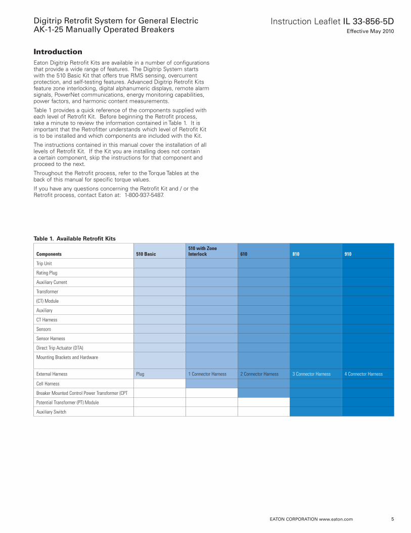
IntroductionEaton Digitrip Retrofit Kits are available in a number of configurations that provide a wide range of features . The Digitrip System starts with the 510 Basic Kit that offers true RMS sensing, overcurrent protection, and self-testing features . Advanced Digitrip Retrofit Kits feature zone interlocking, digital alphanumeric displays, remote alarm signals, PowerNet communications, energy monitoring capabilities, power factors, and harmonic content measurements .
Table 1 provides a quick reference of the components supplied with each level of Retrofit Kit . Before beginning the Retrofit process, take a minute to review the information contained in Table 1 . It is important that the Retrofitter understands which level of Retrofit Kit is to be installed and which components are included with the Kit .
The instructions contained in this manual cover the installation of all levels of Retrofit Kit . If the Kit you are installing does not contain a certain component, skip the instructions for that component and proceed to the next .
Throughout the Retrofit process, refer to the Torque Tables at the back of this manual for specific torque values .
If you have any questions concerning the Retrofit Kit and / or the Retrofit process, contact Eaton at: 1-800-937-5487 .
Table 1. Available Retrofit Kits
Components 510 Basic510 with Zone Interlock 610 810 910
Trip Unit
Rating Plug
Auxiliary Current
Transformer
(CT) Module
Auxiliary
CT Harness
Sensors
Sensor Harness
Direct Trip Actuator (DTA)
Mounting Brackets and Hardware
External Harness Plug 1 Connector Harness 2 Connector Harness 3 Connector Harness 4 Connector Harness
Cell Harness
Breaker Mounted Control Power Transformer (CPT
Potential Transformer (PT) Module
Auxiliary Switch
Digitrip Retrofit System for General ElectricAK-1-25 Manually Operated Breakers
Instructional Leaflet IL 33-856-5DEffective May 2010
6 EATON CORPORATION www.eaton.com
STEP 1: GENERAL BREAKER PREPARATION
Before attempting to remove the Breaker from theCell or perform any Retrofit Operation, be sure toread and understand the Safety Precautionssection of this manual. In addition, be sure to readand understand the Instructions for the Applicationof Digitrip RMS Retrofit Kits on Power CircuitBreakers (Retrofit Application Data - PublicationAD 33-855), supplied with the Digitrip Retrofit Kit.
WARNING
DO NOT ATTEMPT TO INSTALL OR PERFORMMAINTENANCE ON EQUIPMENT WHILE IT ISENERGIZED. SEVERE PERSONAL INJURY ORDEATH CAN RESULT FROM CONTACT WITHENERGIZED EQUIPMENT. VERIFY THAT NOVOLTAGE IS PRESENT BEFORE PROCEEDING.
A. Trip the Breaker and remove it from the Cell.Move the Breaker to a clean, well-lit work area.
NOTE: It is the responsibility of the Retrofitter toinsure that the Breaker and all originalcomponents are in good condition. Visu-ally inspect all Breaker components forsigns of damage or wear. If any signs ofdamage or wear are detected for compo-nents not included in the Retrofit Kit,secure the necessary replacement partsbefore beginning the Retrofit Process.
The force necessary to trip the Breakershould not exceed three (3) lbs.
NOTE: It is the responsibility of the Retrofitter toinsure that the proper, manufacturer’srecommended crimping tools and termi-nals are used for each type of connector.It is also the responsibility of the Retrofitterto insure that all wire preparations, con-nections, strippings, terminations, andwiring techniques are performed accord-ing to the latest IEEE, NEC, and / or NEMAindustry standards, specifications, codes,and guidelines.
To begin the Retrofit Process, refer to the compo-nents list at the end of this manual. Layout thecomponents and hardware according to the stepsoutlined. The parts bags are labeled with thecorresponding step number. The components andhardware will be used to complete each step in theRetrofit Process.
Instructional Leaflet IL 33-856-5DEffective May 2010
Digitrip Retrofit System for General ElectricAK-1-25 Manually Operated Breakers
EATON CORPORATION www.eaton.com 7
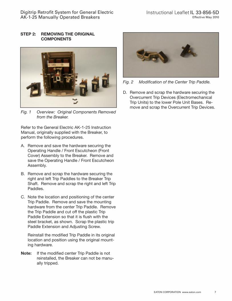
STEP 2: REMOVING THE ORIGINALCOMPONENTS
Fig. 1 Overview: Original Components Removedfrom the Breaker.
Refer to the General Electric AK-1-25 InstructionManual, originally supplied with the Breaker, toperform the following procedures.
A. Remove and save the hardware securing theOperating Handle / Front Escutcheon (FrontCover) Assembly to the Breaker. Remove andsave the Operating Handle / Front EscutcheonAssembly.
B. Remove and scrap the hardware securing theright and left Trip Paddles to the Breaker TripShaft. Remove and scrap the right and left TripPaddles.
C. Note the location and positioning of the centerTrip Paddle. Remove and save the mountinghardware from the center Trip Paddle. Removethe Trip Paddle and cut off the plastic TripPaddle Extension so that it is flush with thesteel bracket, as shown. Scrap the plastic tripPaddle Extension and Adjusting Screw.
Reinstall the modified Trip Paddle in its originallocation and position using the original mount-ing hardware.
Note: If the modified center Trip Paddle is notreinstalled, the Breaker can not be manu-ally tripped.
Fig. 2 Modification of the Center Trip Paddle.
D. Remove and scrap the hardware securing theOvercurrent Trip Devices (ElectromechanicalTrip Units) to the lower Pole Unit Bases. Re-move and scrap the Overcurrent Trip Devices.
Digitrip Retrofit System for General ElectricAK-1-25 Manually Operated Breakers
Instructional Leaflet IL 33-856-5DEffective May 2010
8 EATON CORPORATION www.eaton.com
STEP 3: INSTALLING THE COPPERADAPTERS, SENSORS, ANDSENSOR HARNESS
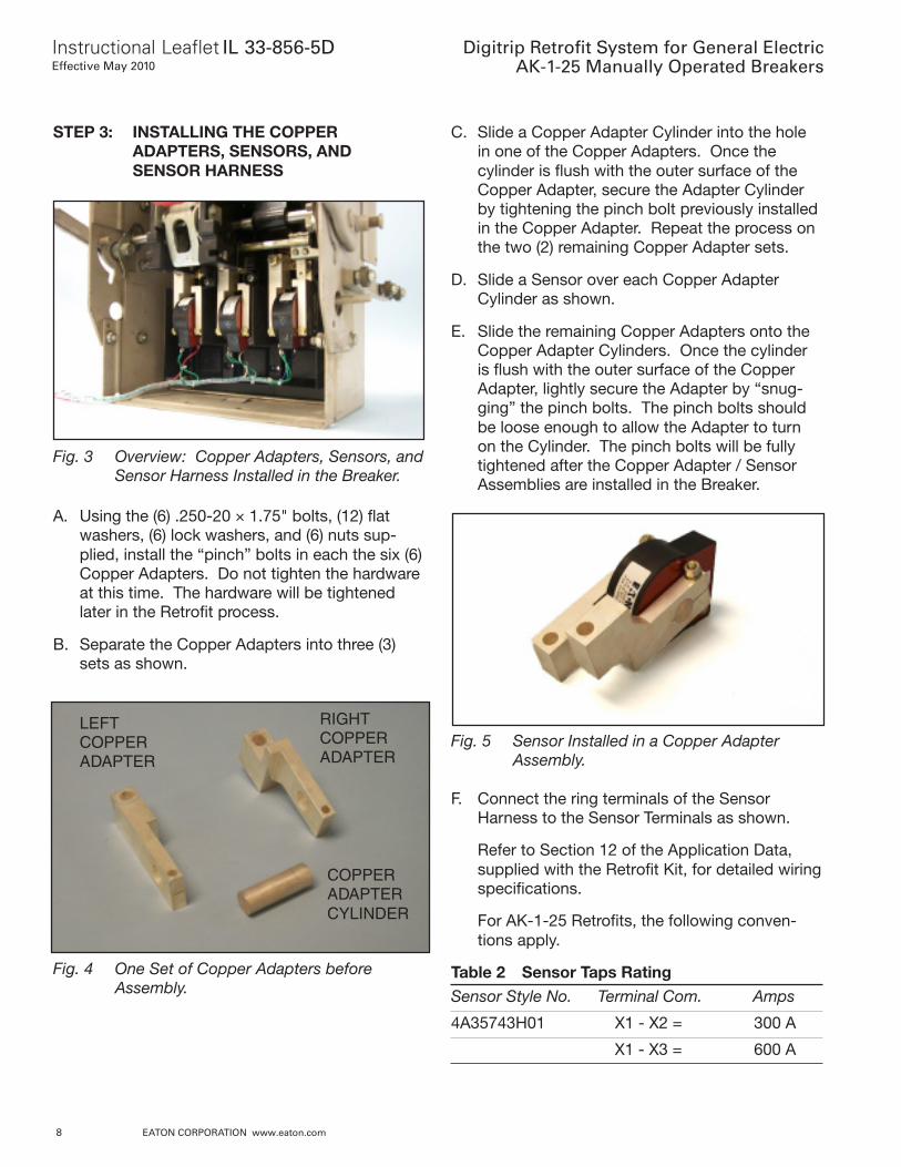
Fig. 3 Overview: Copper Adapters, Sensors, andSensor Harness Installed in the Breaker.
A. Using the (6) .250-20 × 1.75" bolts, (12) flatwashers, (6) lock washers, and (6) nuts sup-plied, install the “pinch” bolts in each the six (6)Copper Adapters. Do not tighten the hardwareat this time. The hardware will be tightenedlater in the Retrofit process.
B. Separate the Copper Adapters into three (3)sets as shown.
LEFTCOPPERADAPTER
RIGHTCOPPERADAPTER
COPPERADAPTERCYLINDER
Fig. 4 One Set of Copper Adapters beforeAssembly.
C. Slide a Copper Adapter Cylinder into the holein one of the Copper Adapters. Once thecylinder is flush with the outer surface of theCopper Adapter, secure the Adapter Cylinderby tightening the pinch bolt previously installedin the Copper Adapter. Repeat the process onthe two (2) remaining Copper Adapter sets.
D. Slide a Sensor over each Copper AdapterCylinder as shown.
E. Slide the remaining Copper Adapters onto theCopper Adapter Cylinders. Once the cylinderis flush with the outer surface of the CopperAdapter, lightly secure the Adapter by “snug-ging” the pinch bolts. The pinch bolts shouldbe loose enough to allow the Adapter to turnon the Cylinder. The pinch bolts will be fullytightened after the Copper Adapter / SensorAssemblies are installed in the Breaker.
Fig. 5 Sensor Installed in a Copper AdapterAssembly.
F. Connect the ring terminals of the SensorHarness to the Sensor Terminals as shown.
Refer to Section 12 of the Application Data,supplied with the Retrofit Kit, for detailed wiringspecifications.
For AK-1-25 Retrofits, the following conven-tions apply.
Table 2 Sensor Taps RatingSensor Style No. Terminal Com. Amps
4A35743H01 X1 - X2 = 300 A
X1 - X3 = 600 A
Instructional Leaflet IL 33-856-5DEffective May 2010
Digitrip Retrofit System for General ElectricAK-1-25 Manually Operated Breakers
EATON CORPORATION www.eaton.com 9
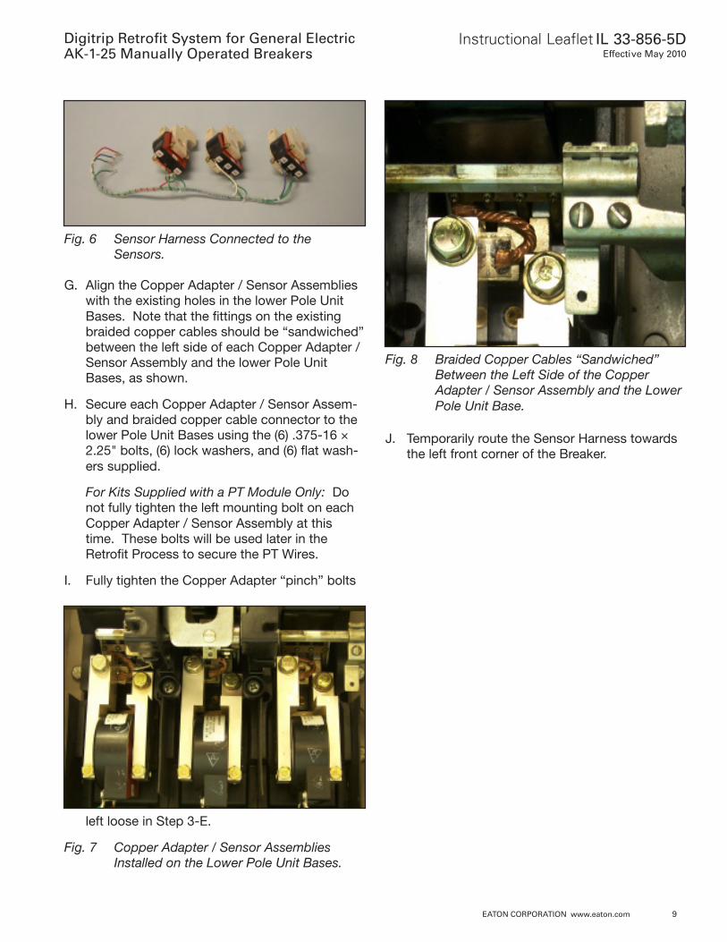
Fig. 6 Sensor Harness Connected to theSensors.
G. Align the Copper Adapter / Sensor Assemblieswith the existing holes in the lower Pole UnitBases. Note that the fittings on the existingbraided copper cables should be “sandwiched”between the left side of each Copper Adapter /Sensor Assembly and the lower Pole UnitBases, as shown.
H. Secure each Copper Adapter / Sensor Assem-bly and braided copper cable connector to thelower Pole Unit Bases using the (6) .375-16 ×2.25" bolts, (6) lock washers, and (6) flat wash-ers supplied.
For Kits Supplied with a PT Module Only: Donot fully tighten the left mounting bolt on eachCopper Adapter / Sensor Assembly at thistime. These bolts will be used later in theRetrofit Process to secure the PT Wires.
I. Fully tighten the Copper Adapter “pinch” bolts
left loose in Step 3-E.
Fig. 7 Copper Adapter / Sensor AssembliesInstalled on the Lower Pole Unit Bases.
Fig. 8 Braided Copper Cables “Sandwiched”Between the Left Side of the CopperAdapter / Sensor Assembly and the LowerPole Unit Base.
J. Temporarily route the Sensor Harness towardsthe left front corner of the Breaker.
Digitrip Retrofit System for General ElectricAK-1-25 Manually Operated Breakers
Instructional Leaflet IL 33-856-5DEffective May 2010
10 EATON CORPORATION www.eaton.com
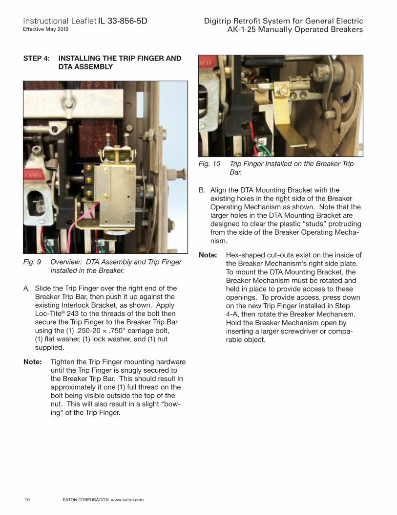
STEP 4: INSTALLING THE TRIP FINGER ANDDTA ASSEMBLY
Fig. 9 Overview: DTA Assembly and Trip FingerInstalled in the Breaker.
A. Slide the Trip Finger over the right end of theBreaker Trip Bar, then push it up against theexisting Interlock Bracket, as shown. ApplyLoc-Tite® 243 to the threads of the bolt thensecure the Trip Finger to the Breaker Trip Barusing the (1) .250-20 × .750" carriage bolt,(1) flat washer, (1) lock washer, and (1) nutsupplied.
Note: Tighten the Trip Finger mounting hardwareuntil the Trip Finger is snugly secured tothe Breaker Trip Bar. This should result inapproximately it one (1) full thread on thebolt being visible outside the top of thenut. This will also result in a slight “bow-ing” of the Trip Finger.
Fig. 10 Trip Finger Installed on the Breaker TripBar.
B. Align the DTA Mounting Bracket with theexisting holes in the right side of the BreakerOperating Mechanism as shown. Note that thelarger holes in the DTA Mounting Bracket aredesigned to clear the plastic “studs” protrudingfrom the side of the Breaker Operating Mecha-nism.
Note: Hex-shaped cut-outs exist on the inside ofthe Breaker Mechanism’s right side plate.To mount the DTA Mounting Bracket, theBreaker Mechanism must be rotated andheld in place to provide access to theseopenings. To provide access, press downon the new Trip Finger installed in Step4-A, then rotate the Breaker Mechanism.Hold the Breaker Mechanism open byinserting a larger screwdriver or compa-rable object.
Instructional Leaflet IL 33-856-5DEffective May 2010
Digitrip Retrofit System for General ElectricAK-1-25 Manually Operated Breakers
EATON CORPORATION www.eaton.com 11
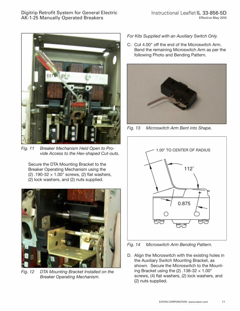
Fig. 11 Breaker Mechanism Held Open to Pro-vide Access to the Hex-shaped Cut-outs.
Secure the DTA Mounting Bracket to theBreaker Operating Mechanism using the(2) .190-32 × 1.00" screws, (2) flat washers,(2) lock washers, and (2) nuts supplied.
Fig. 13 Microswitch Arm Bent into Shape.
Fig. 12 DTA Mounting Bracket Installed on theBreaker Operating Mechanism.
Fig. 14 Microswitch Arm Bending Pattern.
D. Align the Microswitch with the existing holes inthe Auxiliary Switch Mounting Bracket, asshown. Secure the Microswitch to the Mount-ing Bracket using the (2) .138-32 × 1.00"screws, (4) flat washers, (2) lock washers, and(2) nuts supplied.
For Kits Supplied with an Auxiliary Switch Only.
C. Cut 4.00" off the end of the Microswitch Arm.Bend the remaining Microswitch Arm as per thefollowing Photo and Bending Pattern.
0.875
112˚
1.00" TO CENTER OF RADIUS
Digitrip Retrofit System for General ElectricAK-1-25 Manually Operated Breakers
Instructional Leaflet IL 33-856-5DEffective May 2010
12 EATON CORPORATION www.eaton.com
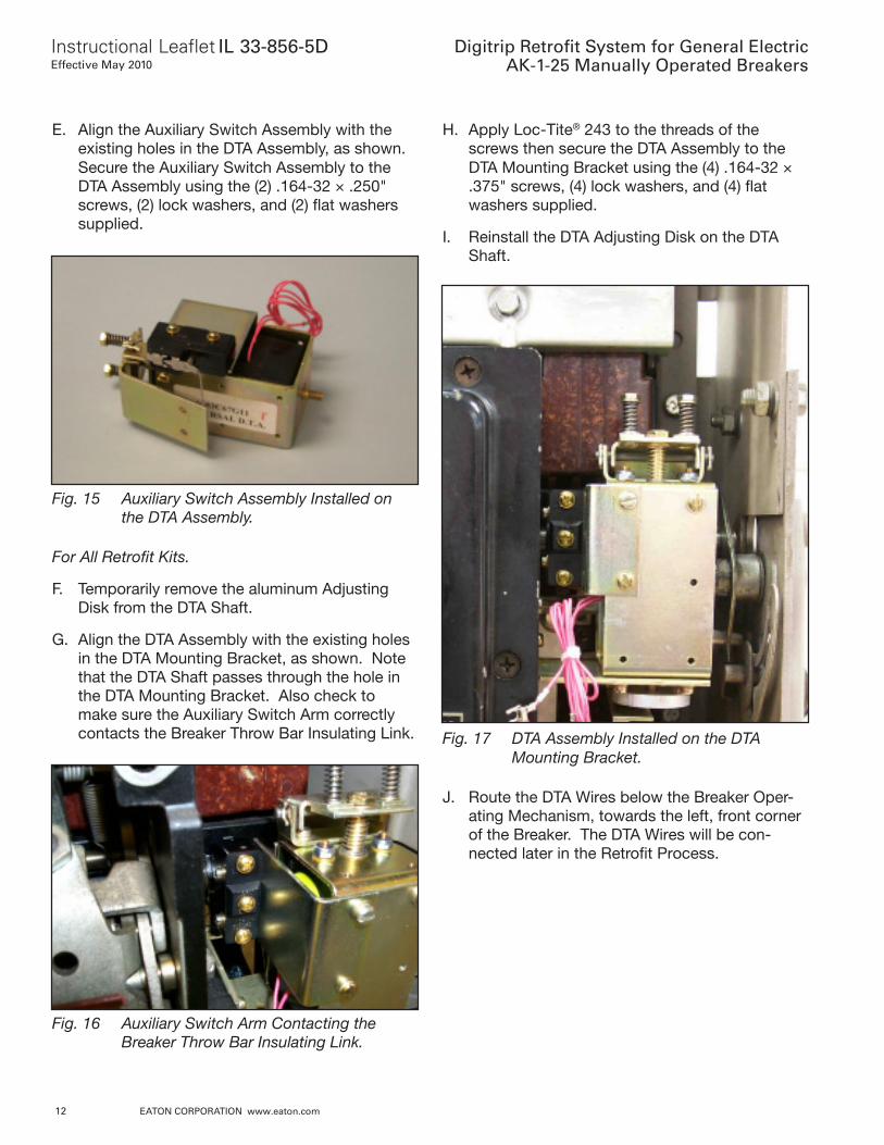
E. Align the Auxiliary Switch Assembly with theexisting holes in the DTA Assembly, as shown.Secure the Auxiliary Switch Assembly to theDTA Assembly using the (2) .164-32 × .250"screws, (2) lock washers, and (2) flat washerssupplied.
H. Apply Loc-Tite® 243 to the threads of thescrews then secure the DTA Assembly to theDTA Mounting Bracket using the (4) .164-32 ×.375" screws, (4) lock washers, and (4) flatwashers supplied.
I. Reinstall the DTA Adjusting Disk on the DTAShaft.
Fig. 15 Auxiliary Switch Assembly Installed onthe DTA Assembly.
For All Retrofit Kits.
F. Temporarily remove the aluminum AdjustingDisk from the DTA Shaft.
G. Align the DTA Assembly with the existing holesin the DTA Mounting Bracket, as shown. Notethat the DTA Shaft passes through the hole inthe DTA Mounting Bracket. Also check tomake sure the Auxiliary Switch Arm correctlycontacts the Breaker Throw Bar Insulating Link.
Fig. 16 Auxiliary Switch Arm Contacting theBreaker Throw Bar Insulating Link.
Fig. 17 DTA Assembly Installed on the DTAMounting Bracket.
J. Route the DTA Wires below the Breaker Oper-ating Mechanism, towards the left, front cornerof the Breaker. The DTA Wires will be con-nected later in the Retrofit Process.
Instructional Leaflet IL 33-856-5DEffective May 2010
Digitrip Retrofit System for General ElectricAK-1-25 Manually Operated Breakers
EATON CORPORATION www.eaton.com 13
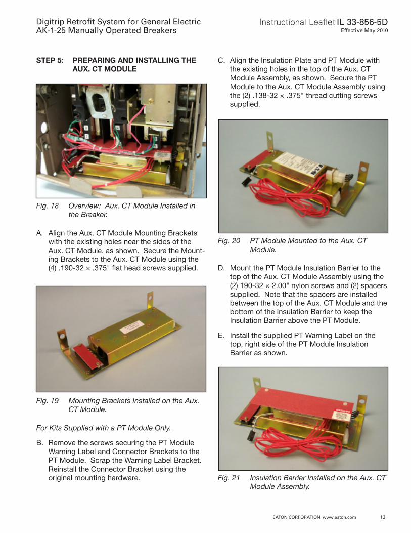
STEP 5: PREPARING AND INSTALLING THEAUX. CT MODULE
C. Align the Insulation Plate and PT Module withthe existing holes in the top of the Aux. CTModule Assembly, as shown. Secure the PTModule to the Aux. CT Module Assembly usingthe (2) .138-32 × .375" thread cutting screwssupplied.
Fig. 18 Overview: Aux. CT Module Installed inthe Breaker.
A. Align the Aux. CT Module Mounting Bracketswith the existing holes near the sides of theAux. CT Module, as shown. Secure the Mount-ing Brackets to the Aux. CT Module using the(4) .190-32 × .375" flat head screws supplied.
Fig. 19 Mounting Brackets Installed on the Aux.CT Module.
For Kits Supplied with a PT Module Only.
B. Remove the screws securing the PT ModuleWarning Label and Connector Brackets to thePT Module. Scrap the Warning Label Bracket.Reinstall the Connector Bracket using theoriginal mounting hardware.
Fig. 20 PT Module Mounted to the Aux. CTModule.
D. Mount the PT Module Insulation Barrier to thetop of the Aux. CT Module Assembly using the(2) 190-32 × 2.00" nylon screws and (2) spacerssupplied. Note that the spacers are installedbetween the top of the Aux. CT Module and thebottom of the Insulation Barrier to keep theInsulation Barrier above the PT Module.
E. Install the supplied PT Warning Label on thetop, right side of the PT Module InsulationBarrier as shown.
Fig. 21 Insulation Barrier Installed on the Aux. CTModule Assembly.
Digitrip Retrofit System for General ElectricAK-1-25 Manually Operated Breakers
Instructional Leaflet IL 33-856-5DEffective May 2010
14 EATON CORPORATION www.eaton.com
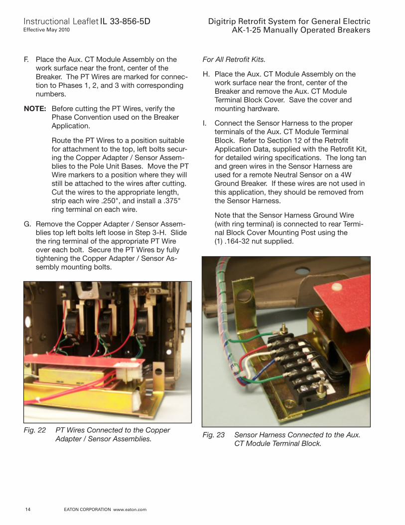
F. Place the Aux. CT Module Assembly on thework surface near the front, center of theBreaker. The PT Wires are marked for connec-tion to Phases 1, 2, and 3 with correspondingnumbers.
NOTE: Before cutting the PT Wires, verify thePhase Convention used on the BreakerApplication.
Route the PT Wires to a position suitablefor attachment to the top, left bolts secur-ing the Copper Adapter / Sensor Assem-blies to the Pole Unit Bases. Move the PTWire markers to a position where they willstill be attached to the wires after cutting.Cut the wires to the appropriate length,strip each wire .250", and install a .375"ring terminal on each wire.
G. Remove the Copper Adapter / Sensor Assem-blies top left bolts left loose in Step 3-H. Slidethe ring terminal of the appropriate PT Wireover each bolt. Secure the PT Wires by fullytightening the Copper Adapter / Sensor As-sembly mounting bolts.
For All Retrofit Kits.
H. Place the Aux. CT Module Assembly on thework surface near the front, center of theBreaker and remove the Aux. CT ModuleTerminal Block Cover. Save the cover andmounting hardware.
I. Connect the Sensor Harness to the properterminals of the Aux. CT Module TerminalBlock. Refer to Section 12 of the RetrofitApplication Data, supplied with the Retrofit Kit,for detailed wiring specifications. The long tanand green wires in the Sensor Harness areused for a remote Neutral Sensor on a 4WGround Breaker. If these wires are not used inthis application, they should be removed fromthe Sensor Harness.
Note that the Sensor Harness Ground Wire(with ring terminal) is connected to rear Termi-nal Block Cover Mounting Post using the(1) .164-32 nut supplied.
Fig. 22 PT Wires Connected to the CopperAdapter / Sensor Assemblies. Fig. 23 Sensor Harness Connected to the Aux.
CT Module Terminal Block.
Instructional Leaflet IL 33-856-5DEffective May 2010
Digitrip Retrofit System for General ElectricAK-1-25 Manually Operated Breakers
EATON CORPORATION www.eaton.com 15
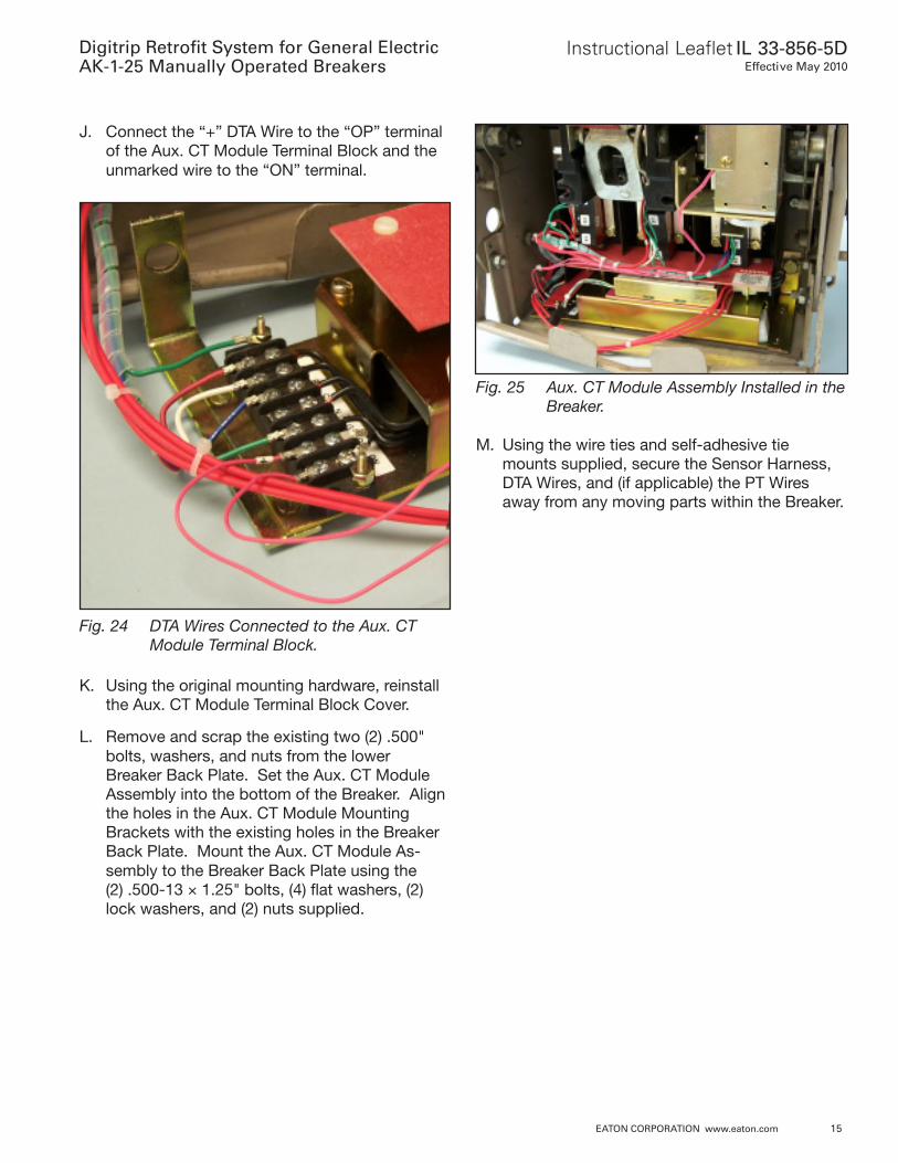
J. Connect the “+” DTA Wire to the “OP” terminalof the Aux. CT Module Terminal Block and theunmarked wire to the “ON” terminal.
Fig. 24 DTA Wires Connected to the Aux. CTModule Terminal Block.
K. Using the original mounting hardware, reinstallthe Aux. CT Module Terminal Block Cover.
L. Remove and scrap the existing two (2) .500"bolts, washers, and nuts from the lowerBreaker Back Plate. Set the Aux. CT ModuleAssembly into the bottom of the Breaker. Alignthe holes in the Aux. CT Module MountingBrackets with the existing holes in the BreakerBack Plate. Mount the Aux. CT Module As-sembly to the Breaker Back Plate using the(2) .500-13 × 1.25" bolts, (4) flat washers, (2)lock washers, and (2) nuts supplied.
Fig. 25 Aux. CT Module Assembly Installed in theBreaker.
M. Using the wire ties and self-adhesive tiemounts supplied, secure the Sensor Harness,DTA Wires, and (if applicable) the PT Wiresaway from any moving parts within the Breaker.
Digitrip Retrofit System for General ElectricAK-1-25 Manually Operated Breakers
Instructional Leaflet IL 33-856-5DEffective May 2010
16 EATON CORPORATION www.eaton.com
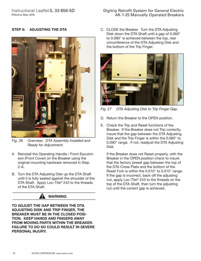
STEP 6: ADJUSTING THE DTA C. CLOSE the Breaker. Turn the DTA AdjustingDisk down the DTA Shaft until a gap of 0.060"to 0.090" is achieved between the top, rearcircumference of the DTA Adjusting Disk andthe bottom of the Trip Finger.
Fig. 26 Overview: DTA Assembly Installed andReady for Adjustment.
A Reinstall the Operating Handle / Front Escutch-eon (Front Cover) on the Breaker using theoriginal mounting hardware removed in Step2-A.
B. Turn the DTA Adjusting Disk up the DTA Shaftuntil it is fully seated against the shoulder of theDTA Shaft. Apply Loc-Tite® 243 to the threadsof the DTA Shaft.
WARNING
TO ADJUST THE GAP BETWEEN THE DTAADJUSTING DISK AND TRIP FINGER, THEBREAKER MUST BE IN THE CLOSED POSI-TION. KEEP HANDS AND FINGERS AWAYFROM MOVING PARTS WITHIN THE BREAKER.FAILURE TO DO SO COULD RESULT IN SEVEREPERSONAL INJURY.
Fig. 27 DTA Adjusting Disk to Trip Finger Gap.
D. Return the Breaker to the OPEN position.
E. Check the Trip and Reset functions of theBreaker. If the Breaker does not Trip correctly,insure that the gap between the DTA AdjustingDisk and the Trip Finger is within the 0.060" to0.090" range. If not, readjust the DTA AdjustingDisk
If the Breaker does not Reset properly, with theBreaker in the OPEN position check to insurethat the factory preset gap between the top ofthe DTA Cross Plate and the bottom of theReset Fork is within the 0.010" to 0.015" range.If the gap is incorrect, back off the adjustingnut, apply Loc-Tite® 243 to the threads on thetop of the DTA Shaft, then turn the adjustingnut until the correct gap is achieved.
GAP0.060"TO0.090"
Instructional Leaflet IL 33-856-5DEffective May 2010
Digitrip Retrofit System for General ElectricAK-1-25 Manually Operated Breakers
EATON CORPORATION www.eaton.com 17
Fig. 28 DTA Cross Plate to Reset Fork Gap.
GAP0.010"TO0.015"
STEP 7: PREPARING AND INSTALLING THETRIP UNIT ASSEMBLY
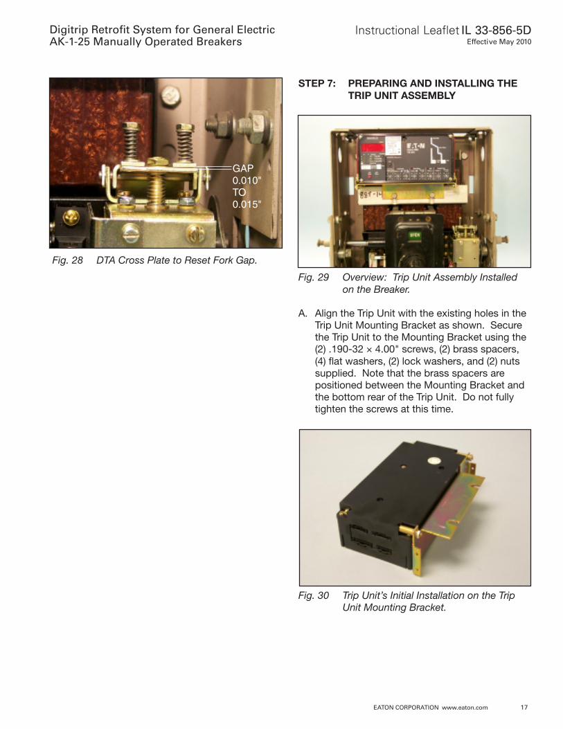
Fig. 29 Overview: Trip Unit Assembly Installedon the Breaker.
A. Align the Trip Unit with the existing holes in theTrip Unit Mounting Bracket as shown. Securethe Trip Unit to the Mounting Bracket using the(2) .190-32 × 4.00" screws, (2) brass spacers,(4) flat washers, (2) lock washers, and (2) nutssupplied. Note that the brass spacers arepositioned between the Mounting Bracket andthe bottom rear of the Trip Unit. Do not fullytighten the screws at this time.
Fig. 30 Trip Unit’s Initial Installation on the TripUnit Mounting Bracket.
Digitrip Retrofit System for General ElectricAK-1-25 Manually Operated Breakers
Instructional Leaflet IL 33-856-5DEffective May 2010
18 EATON CORPORATION www.eaton.com
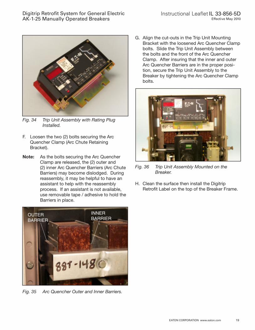
B. Align the right and left Trip Unit Support Clipswith the existing holes in the Trip Unit MountingBracket and the slots in the sides of the TripUnit. Note that the Trip Unit Support Clips“pinch” in the slots on the sides of the Trip Unitas shown. Secure the Support Clips to the TripUnit Plate Mounting Bracket using the (4) .138-32 × .500" screws, (8) flat washers, (4) lockwashers, and (4) nuts supplied.
Once the Support Clips have been installed,fully tighten the (2) 4.00" screws, installed inStep 7-A, securing the Trip Unit to the Trip UnitMounting Bracket.
Fig. 31 Trip Unit Support Clips Installed on theTrip Unit and Mounting Bracket.
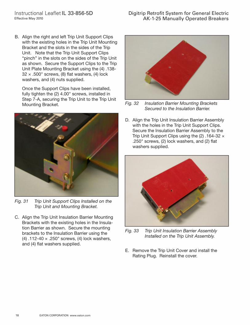
C. Align the Trip Unit Insulation Barrier MountingBrackets with the existing holes in the Insula-tion Barrier as shown. Secure the mountingbrackets to the Insulation Barrier using the(4) .112-40 × .250" screws, (4) lock washers,and (4) flat washers supplied.
Fig. 32 Insulation Barrier Mounting BracketsSecured to the Insulation Barrier.
D. Align the Trip Unit Insulation Barrier Assemblywith the holes in the Trip Unit Support Clips.Secure the Insulation Barrier Assembly to theTrip Unit Support Clips using the (2) .164-32 ×.250" screws, (2) lock washers, and (2) flatwashers supplied.
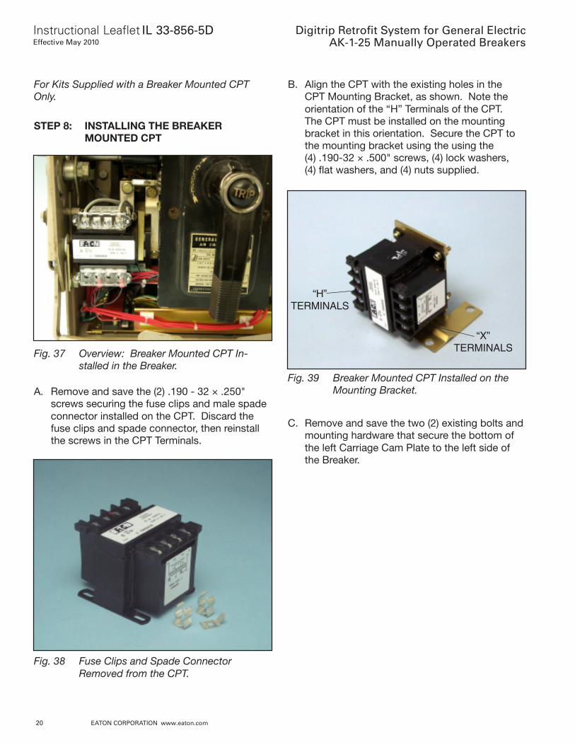
Fig. 33 Trip Unit Insulation Barrier AssemblyInstalled on the Trip Unit Assembly.
E. Remove the Trip Unit Cover and install theRating Plug. Reinstall the cover.
Instructional Leaflet IL 33-856-5DEffective May 2010
Digitrip Retrofit System for General ElectricAK-1-25 Manually Operated Breakers
EATON CORPORATION www.eaton.com 19
Fig. 34 Trip Unit Assembly with Rating PlugInstalled.
F. Loosen the two (2) bolts securing the ArcQuencher Clamp (Arc Chute RetainingBracket).
Note: As the bolts securing the Arc QuencherClamp are released, the (2) outer and(2) inner Arc Quencher Barriers (Arc ChuteBarriers) may become dislodged. Duringreassembly, it may be helpful to have anassistant to help with the reassemblyprocess. If an assistant is not available,use removable tape / adhesive to hold theBarriers in place.
Fig. 35 Arc Quencher Outer and Inner Barriers.
OUTERBARRIER
INNERBARRIER
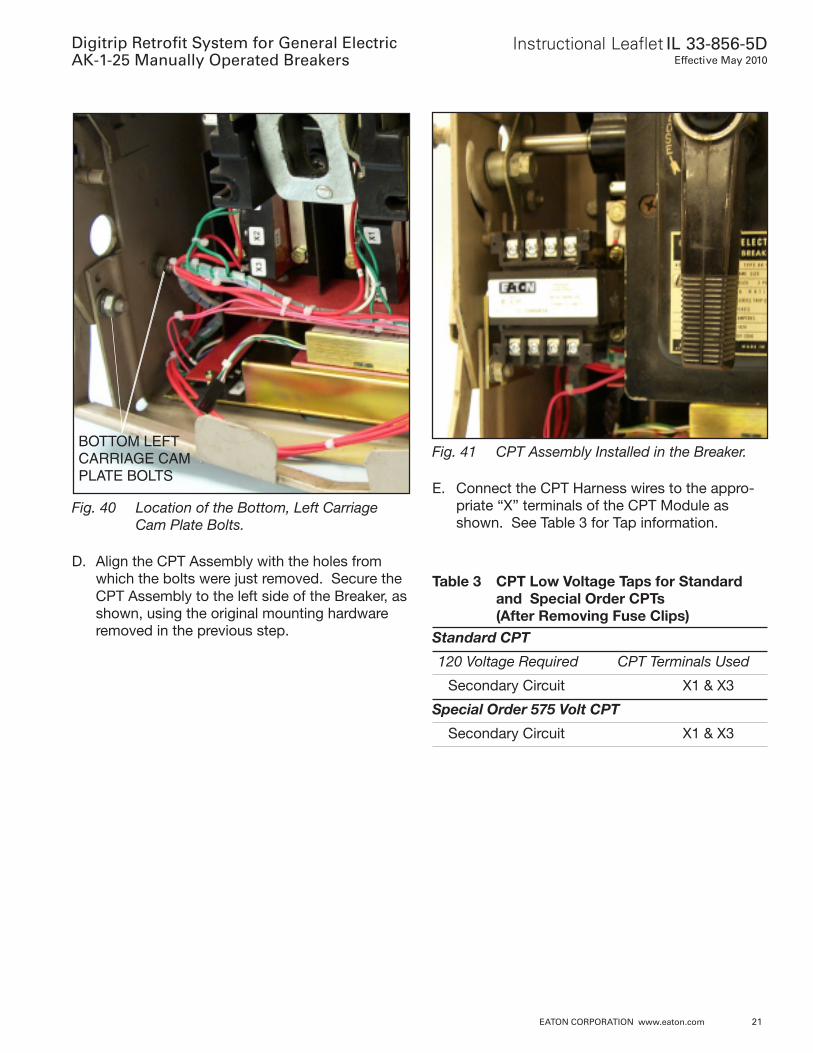
G. Align the cut-outs in the Trip Unit MountingBracket with the loosened Arc Quencher Clampbolts. Slide the Trip Unit Assembly betweenthe bolts and the front of the Arc QuencherClamp. After insuring that the inner and outerArc Quencher Barriers are in the proper posi-tion, secure the Trip Unit Assembly to theBreaker by tightening the Arc Quencher Clampbolts.
Fig. 36 Trip Unit Assembly Mounted on theBreaker.
H. Clean the surface then install the DigitripRetrofit Label on the top of the Breaker Frame.
Digitrip Retrofit System for General ElectricAK-1-25 Manually Operated Breakers
Instructional Leaflet IL 33-856-5DEffective May 2010
20 EATON CORPORATION www.eaton.com
For Kits Supplied with a Breaker Mounted CPTOnly.
STEP 8: INSTALLING THE BREAKERMOUNTED CPT
B. Align the CPT with the existing holes in theCPT Mounting Bracket, as shown. Note theorientation of the “H” Terminals of the CPT.The CPT must be installed on the mountingbracket in this orientation. Secure the CPT tothe mounting bracket using the using the(4) .190-32 × .500" screws, (4) lock washers,(4) flat washers, and (4) nuts supplied.
Fig. 37 Overview: Breaker Mounted CPT In-stalled in the Breaker.
A. Remove and save the (2) .190 - 32 × .250"screws securing the fuse clips and male spadeconnector installed on the CPT. Discard thefuse clips and spade connector, then reinstallthe screws in the CPT Terminals.
Fig. 38 Fuse Clips and Spade ConnectorRemoved from the CPT.
“H”TERMINALS
“X”TERMINALS
Fig. 39 Breaker Mounted CPT Installed on theMounting Bracket.
C. Remove and save the two (2) existing bolts andmounting hardware that secure the bottom ofthe left Carriage Cam Plate to the left side ofthe Breaker.
Instructional Leaflet IL 33-856-5DEffective May 2010
Digitrip Retrofit System for General ElectricAK-1-25 Manually Operated Breakers
EATON CORPORATION www.eaton.com 21
Fig. 40 Location of the Bottom, Left CarriageCam Plate Bolts.
D. Align the CPT Assembly with the holes fromwhich the bolts were just removed. Secure theCPT Assembly to the left side of the Breaker, asshown, using the original mounting hardwareremoved in the previous step.
BOTTOM LEFTCARRIAGE CAMPLATE BOLTS
Fig. 41 CPT Assembly Installed in the Breaker.
E. Connect the CPT Harness wires to the appro-priate “X” terminals of the CPT Module asshown. See Table 3 for Tap information.
Table 3 CPT Low Voltage Taps for Standardand Special Order CPTs(After Removing Fuse Clips)
Standard CPT
120 Voltage Required CPT Terminals Used
Secondary Circuit X1 & X3
Special Order 575 Volt CPT
Secondary Circuit X1 & X3
Digitrip Retrofit System for General ElectricAK-1-25 Manually Operated Breakers
Instructional Leaflet IL 33-856-5DEffective May 2010
22 EATON CORPORATION www.eaton.com
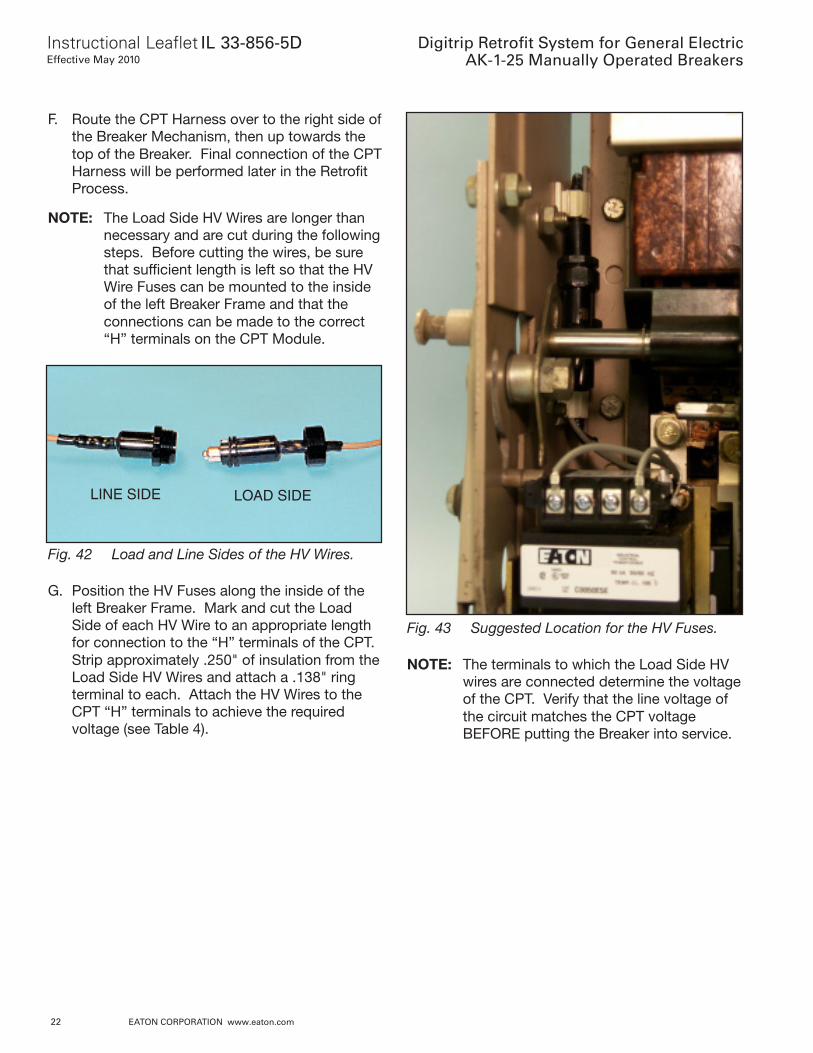
F. Route the CPT Harness over to the right side ofthe Breaker Mechanism, then up towards thetop of the Breaker. Final connection of the CPTHarness will be performed later in the RetrofitProcess.
NOTE: The Load Side HV Wires are longer thannecessary and are cut during the followingsteps. Before cutting the wires, be surethat sufficient length is left so that the HVWire Fuses can be mounted to the insideof the left Breaker Frame and that theconnections can be made to the correct“H” terminals on the CPT Module.
LINE SIDE LOAD SIDE
Fig. 42 Load and Line Sides of the HV Wires.
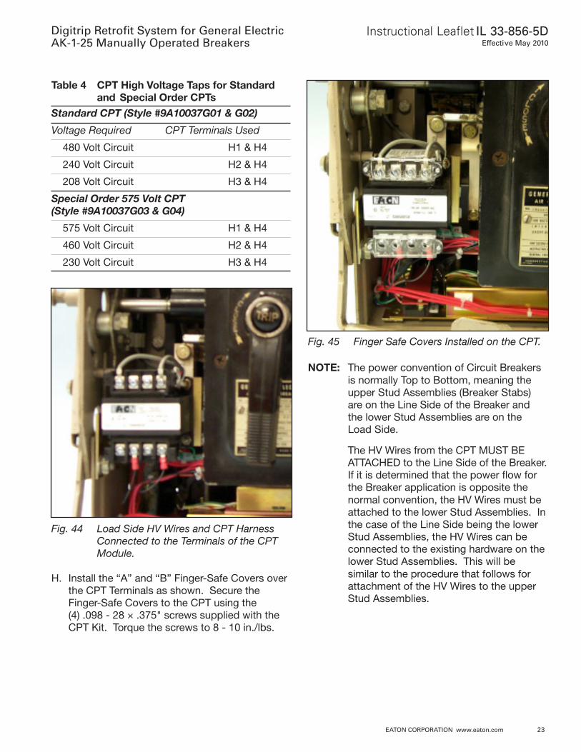
G. Position the HV Fuses along the inside of theleft Breaker Frame. Mark and cut the LoadSide of each HV Wire to an appropriate lengthfor connection to the “H” terminals of the CPT.Strip approximately .250" of insulation from theLoad Side HV Wires and attach a .138" ringterminal to each. Attach the HV Wires to theCPT “H” terminals to achieve the requiredvoltage (see Table 4).
Fig. 43 Suggested Location for the HV Fuses.
NOTE: The terminals to which the Load Side HVwires are connected determine the voltageof the CPT. Verify that the line voltage ofthe circuit matches the CPT voltageBEFORE putting the Breaker into service.
Instructional Leaflet IL 33-856-5DEffective May 2010
Digitrip Retrofit System for General ElectricAK-1-25 Manually Operated Breakers
EATON CORPORATION www.eaton.com 23
Table 4 CPT High Voltage Taps for Standardand Special Order CPTs
Standard CPT (Style #9A10037G01 & G02)
Voltage Required CPT Terminals Used
480 Volt Circuit H1 & H4
240 Volt Circuit H2 & H4
208 Volt Circuit H3 & H4
Special Order 575 Volt CPT(Style #9A10037G03 & G04)
575 Volt Circuit H1 & H4
460 Volt Circuit H2 & H4
230 Volt Circuit H3 & H4
Fig. 44 Load Side HV Wires and CPT HarnessConnected to the Terminals of the CPTModule.
H. Install the “A” and “B” Finger-Safe Covers overthe CPT Terminals as shown. Secure theFinger-Safe Covers to the CPT using the(4) .098 - 28 × .375" screws supplied with theCPT Kit. Torque the screws to 8 - 10 in./lbs.
Fig. 45 Finger Safe Covers Installed on the CPT.
NOTE: The power convention of Circuit Breakersis normally Top to Bottom, meaning theupper Stud Assemblies (Breaker Stabs)are on the Line Side of the Breaker andthe lower Stud Assemblies are on theLoad Side.
The HV Wires from the CPT MUST BEATTACHED to the Line Side of the Breaker.If it is determined that the power flow forthe Breaker application is opposite thenormal convention, the HV Wires must beattached to the lower Stud Assemblies. Inthe case of the Line Side being the lowerStud Assemblies, the HV Wires can beconnected to the existing hardware on thelower Stud Assemblies. This will besimilar to the procedure that follows forattachment of the HV Wires to the upperStud Assemblies.
Digitrip Retrofit System for General ElectricAK-1-25 Manually Operated Breakers
Instructional Leaflet IL 33-856-5DEffective May 2010
24 EATON CORPORATION www.eaton.com
NOTE: The Line Side HV Wires are longer thannecessary and are cut during the followingsteps. Before cutting the wires, be surethat sufficient length is left so that the HVWire Fuses are accessible and that theconnections can be made to the correctStud Assemblies.
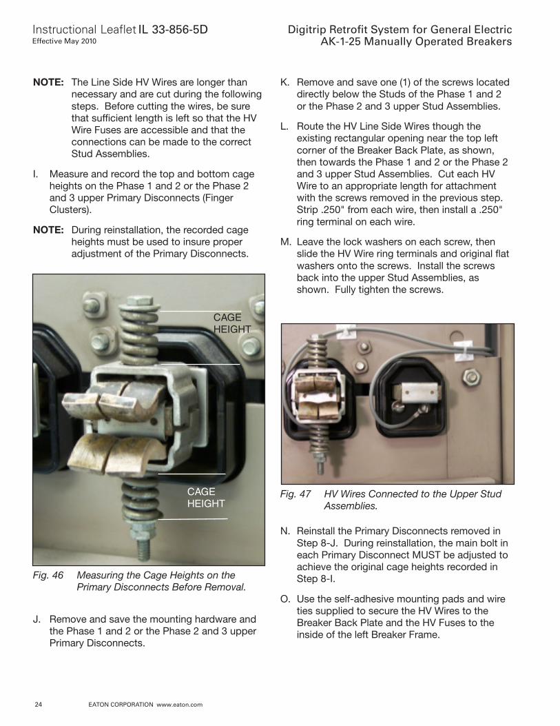
I. Measure and record the top and bottom cageheights on the Phase 1 and 2 or the Phase 2and 3 upper Primary Disconnects (FingerClusters).
NOTE: During reinstallation, the recorded cageheights must be used to insure properadjustment of the Primary Disconnects.
K. Remove and save one (1) of the screws locateddirectly below the Studs of the Phase 1 and 2or the Phase 2 and 3 upper Stud Assemblies.
L. Route the HV Line Side Wires though theexisting rectangular opening near the top leftcorner of the Breaker Back Plate, as shown,then towards the Phase 1 and 2 or the Phase 2and 3 upper Stud Assemblies. Cut each HVWire to an appropriate length for attachmentwith the screws removed in the previous step.Strip .250" from each wire, then install a .250"ring terminal on each wire.
M. Leave the lock washers on each screw, thenslide the HV Wire ring terminals and original flatwashers onto the screws. Install the screwsback into the upper Stud Assemblies, asshown. Fully tighten the screws.
CAGEHEIGHT
CAGEHEIGHT
Fig. 46 Measuring the Cage Heights on thePrimary Disconnects Before Removal.
J. Remove and save the mounting hardware andthe Phase 1 and 2 or the Phase 2 and 3 upperPrimary Disconnects.
Fig. 47 HV Wires Connected to the Upper StudAssemblies.
N. Reinstall the Primary Disconnects removed inStep 8-J. During reinstallation, the main bolt ineach Primary Disconnect MUST be adjusted toachieve the original cage heights recorded inStep 8-I.
O. Use the self-adhesive mounting pads and wireties supplied to secure the HV Wires to theBreaker Back Plate and the HV Fuses to theinside of the left Breaker Frame.
Instructional Leaflet IL 33-856-5DEffective May 2010
Digitrip Retrofit System for General ElectricAK-1-25 Manually Operated Breakers
EATON CORPORATION www.eaton.com 25
Fig. 48 HV Fuses Secured to the Left BreakerFrame.
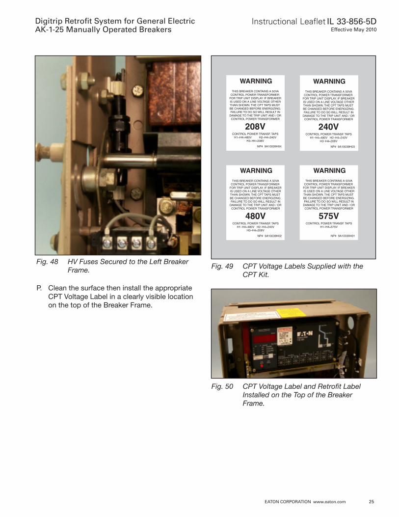
P. Clean the surface then install the appropriateCPT Voltage Label in a clearly visible locationon the top of the Breaker Frame.
208VCONTROL POWER TRANSF. TAPS
H1–H4=480V H2–H4=240VH3–H4=208V
WARNINGTHIS BREAKER CONTAINS A 50VA
CONTROL POWER TRANSFORMER FOR TRIP UNIT DISPLAY. IF BREAKERIS USED ON A LINE VOLTAGE OTHERTHAN SHOWN. THE CPT TAPS MUST BE CHANGED BEFORE ENERGIZING.FAILURE TO DO SO WILL RESULT IN
DAMAGE TO THE TRIP UNIT AND / ORCONTROL POWER TRANSFORMER
NP# 9A10039H04
240VCONTROL POWER TRANSF. TAPS
H1–H4=480V H2–H4=240VH3–H4=208V
WARNINGTHIS BREAKER CONTAINS A 50VA
CONTROL POWER TRANSFORMER FOR TRIP UNIT DISPLAY. IF BREAKERIS USED ON A LINE VOLTAGE OTHERTHAN SHOWN. THE CPT TAPS MUST BE CHANGED BEFORE ENERGIZING.FAILURE TO DO SO WILL RESULT IN
DAMAGE TO THE TRIP UNIT AND / ORCONTROL POWER TRANSFORMER
NP# 9A10039H03
480VCONTROL POWER TRANSF. TAPS
H1–H4=480V H2–H4=240VH3–H4=208V
WARNINGTHIS BREAKER CONTAINS A 50VA
CONTROL POWER TRANSFORMER FOR TRIP UNIT DISPLAY. IF BREAKERIS USED ON A LINE VOLTAGE OTHERTHAN SHOWN. THE CPT TAPS MUST BE CHANGED BEFORE ENERGIZING.FAILURE TO DO SO WILL RESULT IN
DAMAGE TO THE TRIP UNIT AND / ORCONTROL POWER TRANSFORMER
NP# 9A10039H02
575VCONTROL POWER TRANSF. TAPS
H1–H4=575V
WARNINGTHIS BREAKER CONTAINS A 50VA
CONTROL POWER TRANSFORMER FOR TRIP UNIT DISPLAY. IF BREAKERIS USED ON A LINE VOLTAGE OTHERTHAN SHOWN. THE CPT TAPS MUST BE CHANGED BEFORE ENERGIZING.FAILURE TO DO SO WILL RESULT IN
DAMAGE TO THE TRIP UNIT AND / ORCONTROL POWER TRANSFORMER
NP# 9A10039H01
Fig. 49 CPT Voltage Labels Supplied with theCPT Kit.
Fig. 50 CPT Voltage Label and Retrofit LabelInstalled on the Top of the BreakerFrame.
Digitrip Retrofit System for General ElectricAK-1-25 Manually Operated Breakers
Instructional Leaflet IL 33-856-5DEffective May 2010
26 EATON CORPORATION www.eaton.com
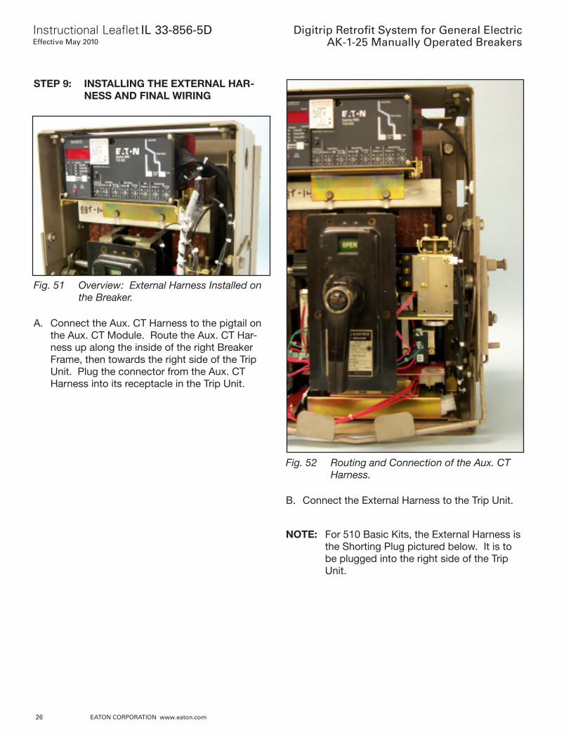
STEP 9: INSTALLING THE EXTERNAL HAR-NESS AND FINAL WIRING
Fig. 51 Overview: External Harness Installed onthe Breaker.
A. Connect the Aux. CT Harness to the pigtail onthe Aux. CT Module. Route the Aux. CT Har-ness up along the inside of the right BreakerFrame, then towards the right side of the TripUnit. Plug the connector from the Aux. CTHarness into its receptacle in the Trip Unit.
Fig. 52 Routing and Connection of the Aux. CTHarness.
B. Connect the External Harness to the Trip Unit.
NOTE: For 510 Basic Kits, the External Harness isthe Shorting Plug pictured below. It is tobe plugged into the right side of the TripUnit.
Instructional Leaflet IL 33-856-5DEffective May 2010
Digitrip Retrofit System for General ElectricAK-1-25 Manually Operated Breakers
EATON CORPORATION www.eaton.com 27
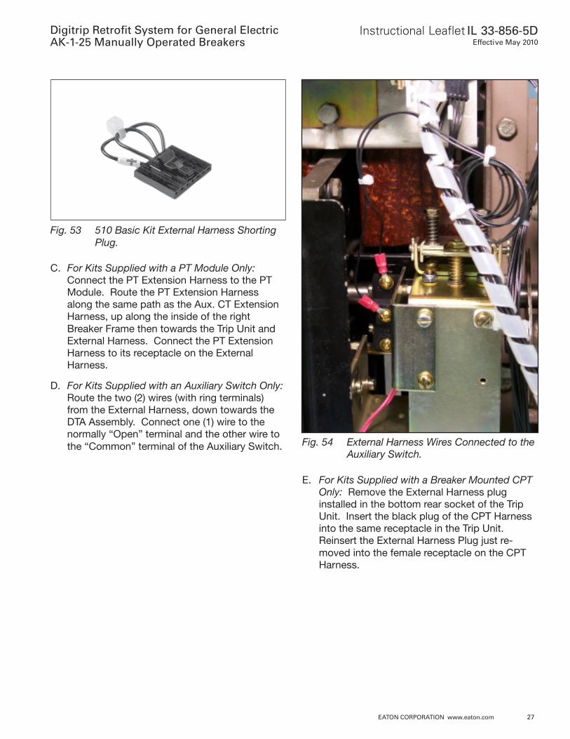
Fig. 53 510 Basic Kit External Harness ShortingPlug.
C. For Kits Supplied with a PT Module Only:Connect the PT Extension Harness to the PTModule. Route the PT Extension Harnessalong the same path as the Aux. CT ExtensionHarness, up along the inside of the rightBreaker Frame then towards the Trip Unit andExternal Harness. Connect the PT ExtensionHarness to its receptacle on the ExternalHarness.
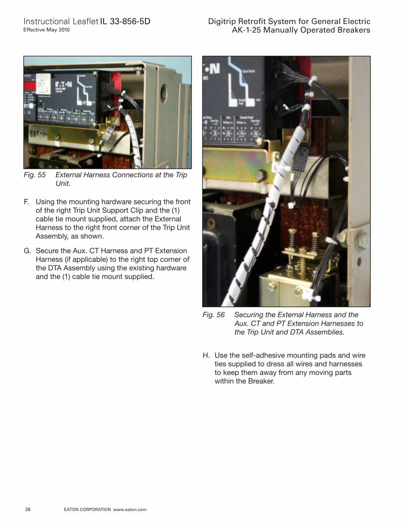
D. For Kits Supplied with an Auxiliary Switch Only:Route the two (2) wires (with ring terminals)from the External Harness, down towards theDTA Assembly. Connect one (1) wire to thenormally “Open” terminal and the other wire tothe “Common” terminal of the Auxiliary Switch. Fig. 54 External Harness Wires Connected to the
Auxiliary Switch.
E. For Kits Supplied with a Breaker Mounted CPTOnly: Remove the External Harness pluginstalled in the bottom rear socket of the TripUnit. Insert the black plug of the CPT Harnessinto the same receptacle in the Trip Unit.Reinsert the External Harness Plug just re-moved into the female receptacle on the CPTHarness.
Digitrip Retrofit System for General ElectricAK-1-25 Manually Operated Breakers
Instructional Leaflet IL 33-856-5DEffective May 2010
28 EATON CORPORATION www.eaton.com
Fig. 55 External Harness Connections at the TripUnit.
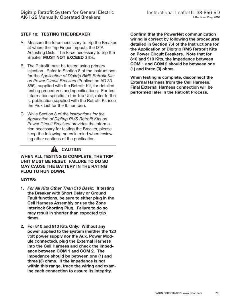
F. Using the mounting hardware securing the frontof the right Trip Unit Support Clip and the (1)cable tie mount supplied, attach the ExternalHarness to the right front corner of the Trip UnitAssembly, as shown.
G. Secure the Aux. CT Harness and PT ExtensionHarness (if applicable) to the right top corner ofthe DTA Assembly using the existing hardwareand the (1) cable tie mount supplied.
Fig. 56 Securing the External Harness and theAux. CT and PT Extension Harnesses tothe Trip Unit and DTA Assemblies.
H. Use the self-adhesive mounting pads and wireties supplied to dress all wires and harnessesto keep them away from any moving partswithin the Breaker.
Instructional Leaflet IL 33-856-5DEffective May 2010
Digitrip Retrofit System for General ElectricAK-1-25 Manually Operated Breakers
EATON CORPORATION www.eaton.com 29
STEP 10: TESTING THE BREAKER
A. Measure the force necessary to trip the Breakerat where the Trip Finger impacts the DTAAdjusting Disk. The force necessary to trip theBreaker MUST NOT EXCEED 3 lbs.
B. The Retrofit must be tested using primaryinjection. Refer to Section 8 of the Instructionsfor the Application of Digitrip RMS Retrofit Kitson Power Circuit Breakers (Publication AD 33-855), supplied with the Retrofit Kit, for detailedtesting procedures and specifications. For testinformation specific to the Trip Unit, refer to theIL publication supplied with the Retrofit Kit (seethe Pick List for the IL number).
C. While Section 8 of the Instructions for theApplication of Digitrip RMS Retrofit Kits onPower Circuit Breakers provides the informa-tion necessary for testing the Breaker, pleasekeep the following notes in mind when review-ing other sections of the publication.
CAUTION
WHEN ALL TESTING IS COMPLETE, THE TRIPUNIT MUST BE RESET. FAILURE TO DO SOMAY CAUSE THE BATTERY IN THE RATINGPLUG TO RUN DOWN.
NOTES:
1. For All Kits Other Than 510 Basic: If testingthe Breaker with Short Delay or GroundFault functions, be sure to either plug in theCell Harness Assembly or use the ZoneInterlock Shorting Plug. Failure to do somay result in shorter than expected triptimes.
2. For 810 and 910 Kits Only: Without anypower applied to the system (neither the 120volt power supply nor the Aux. Power Mod-ule connected), plug the External Harnessinto the Cell Harness and check the imped-ance between COM 1 and COM 2. Theimpedance should be between one (1) andthree (3) ohms. If the impedance is notwithin this range, trace the wiring and exam-ine each connection to assure its integrity.
Confirm that the PowerNet communicationwiring is correct by following the proceduresdetailed in Section 7.4 of the Instructions forthe Application of Digitrip RMS Retrofit Kitson Power Circuit Breakers. Note that for810 and 910 Kits, the impedance betweenCOM 1 and COM 2 should be between one(1) and three (3) ohms.
When testing is complete, disconnect theExternal Harness from the Cell Harness.Final External Harness connection will beperformed later in the Retrofit Process.
Digitrip Retrofit System for General ElectricAK-1-25 Manually Operated Breakers
Instructional Leaflet IL 33-856-5DEffective May 2010
30 EATON CORPORATION www.eaton.com
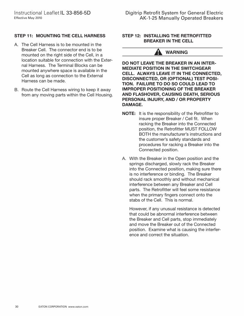
STEP 11: MOUNTING THE CELL HARNESS
A. The Cell Harness is to be mounted in theBreaker Cell. The connector end is to bemounted on the right side of the Cell, in alocation suitable for connection with the Exter-nal Harness. The Terminal Blocks can bemounted anywhere space is available in theCell as long as connection to the ExternalHarness can be made.
B. Route the Cell Harness wiring to keep it awayfrom any moving parts within the Cell Housing.
STEP 12: INSTALLING THE RETROFITTEDBREAKER IN THE CELL
WARNING
DO NOT LEAVE THE BREAKER IN AN INTER-MEDIATE POSITION IN THE SWITCHGEARCELL. ALWAYS LEAVE IT IN THE CONNECTED,DISCONNECTED, OR (OPTIONAL) TEST POSI-TION. FAILURE TO DO SO COULD LEAD TOIMPROPER POSITIONING OF THE BREAKERAND FLASHOVER, CAUSING DEATH, SERIOUSPERSONAL INJURY, AND / OR PROPERTYDAMAGE.
NOTE: It is the responsibility of the Retrofitter toinsure proper Breaker / Cell fit. Whenracking the Breaker into the Connectedposition, the Retrofitter MUST FOLLOWBOTH the manufacturer’s instructions andthe customer’s safety standards andprocedures for racking a Breaker into theConnected position.
A. With the Breaker in the Open position and thesprings discharged, slowly rack the Breakerinto the Connected position, making sure thereis no interference or binding. The Breakershould rack smoothly and without mechanicalinterference between any Breaker and Cellparts. The Retrofitter will feel some resistancewhen the primary fingers connect onto thestabs of the Cell. This is normal.
However, if any unusual resistance is detectedthat could be abnormal interference betweenthe Breaker and Cell parts, stop immediatelyand move the Breaker out of the Connectedposition. Examine what is causing the interfer-ence and correct the situation.
Instructional Leaflet IL 33-856-5DEffective May 2010
Digitrip Retrofit System for General ElectricAK-1-25 Manually Operated Breakers
EATON CORPORATION www.eaton.com 31
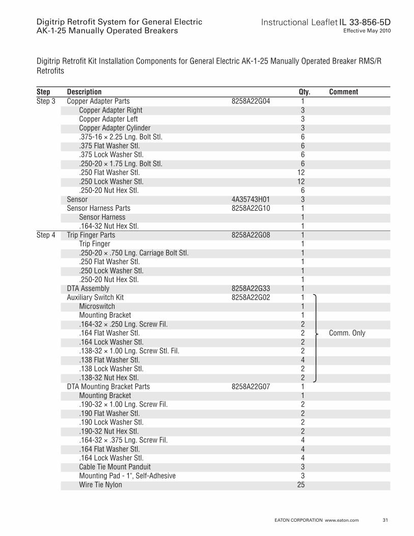
Digitrip Retrofit Kit Installation Components for General Electric AK-1-25 Manually Operated Breaker RMS/RRetrofits
Step Description Qty. CommentStep 3 Copper Adapter Parts 8258A22G04 1
Copper Adapter Right 3Copper Adapter Left 3Copper Adapter Cylinder 3.375-16 × 2.25 Lng. Bolt Stl. 6.375 Flat Washer Stl. 6.375 Lock Washer Stl. 6.250-20 × 1.75 Lng. Bolt Stl. 6.250 Flat Washer Stl. 12.250 Lock Washer Stl. 12.250-20 Nut Hex Stl. 6
Sensor 4A35743H01 3Sensor Harness Parts 8258A22G10 1
Sensor Harness 1.164-32 Nut Hex Stl. 1
Step 4 Trip Finger Parts 8258A22G08 1Trip Finger 1.250-20 × .750 Lng. Carriage Bolt Stl. 1.250 Flat Washer Stl. 1.250 Lock Washer Stl. 1.250-20 Nut Hex Stl. 1
DTA Assembly 8258A22G33 1Auxiliary Switch Kit 8258A22G02 1
Microswitch 1Mounting Bracket 1.164-32 × .250 Lng. Screw Fil. 2.164 Flat Washer Stl. 2 Comm. Only.164 Lock Washer Stl. 2.138-32 × 1.00 Lng. Screw Stl. Fil. 2.138 Flat Washer Stl. 4.138 Lock Washer Stl. 2.138-32 Nut Hex Stl. 2
DTA Mounting Bracket Parts 8258A22G07 1Mounting Bracket 1.190-32 × 1.00 Lng. Screw Fil. 2.190 Flat Washer Stl. 2.190 Lock Washer Stl. 2.190-32 Nut Hex Stl. 2.164-32 × .375 Lng. Screw Fil. 4.164 Flat Washer Stl. 4.164 Lock Washer Stl. 4Cable Tie Mount Panduit 3Mounting Pad - 1", Self-Adhesive 3Wire Tie Nylon 25
Digitrip Retrofit System for General ElectricAK-1-25 Manually Operated Breakers
Instructional Leaflet IL 33-856-5DEffective May 2010
32 EATON CORPORATION www.eaton.com
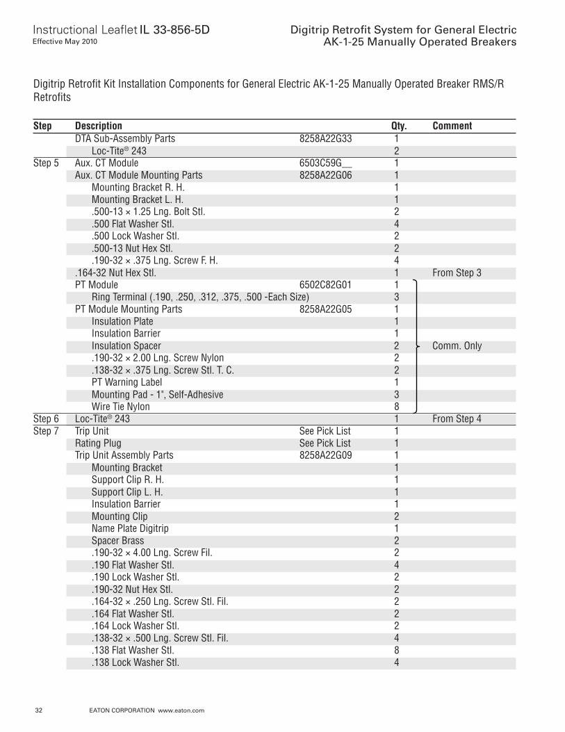
Digitrip Retrofit Kit Installation Components for General Electric AK-1-25 Manually Operated Breaker RMS/RRetrofits
Step Description Qty. CommentDTA Sub-Assembly Parts 8258A22G33 1
Loc-Tite® 243 2Step 5 Aux. CT Module 6503C59G__ 1
Aux. CT Module Mounting Parts 8258A22G06 1Mounting Bracket R. H. 1Mounting Bracket L. H. 1.500-13 × 1.25 Lng. Bolt Stl. 2.500 Flat Washer Stl. 4.500 Lock Washer Stl. 2.500-13 Nut Hex Stl. 2.190-32 × .375 Lng. Screw F. H. 4
.164-32 Nut Hex Stl. 1 From Step 3PT Module 6502C82G01 1
Ring Terminal (.190, .250, .312, .375, .500 -Each Size) 3PT Module Mounting Parts 8258A22G05 1
Insulation Plate 1Insulation Barrier 1Insulation Spacer 2 Comm. Only.190-32 × 2.00 Lng. Screw Nylon 2.138-32 × .375 Lng. Screw Stl. T. C. 2PT Warning Label 1Mounting Pad - 1", Self-Adhesive 3Wire Tie Nylon 8
Step 6 Loc-Tite® 243 1 From Step 4Step 7 Trip Unit See Pick List 1
Rating Plug See Pick List 1Trip Unit Assembly Parts 8258A22G09 1
Mounting Bracket 1Support Clip R. H. 1Support Clip L. H. 1Insulation Barrier 1Mounting Clip 2Name Plate Digitrip 1Spacer Brass 2.190-32 × 4.00 Lng. Screw Fil. 2.190 Flat Washer Stl. 4.190 Lock Washer Stl. 2.190-32 Nut Hex Stl. 2.164-32 × .250 Lng. Screw Stl. Fil. 2.164 Flat Washer Stl. 2.164 Lock Washer Stl. 2.138-32 × .500 Lng. Screw Stl. Fil. 4.138 Flat Washer Stl. 8.138 Lock Washer Stl. 4
Instructional Leaflet IL 33-856-5DEffective May 2010
Digitrip Retrofit System for General ElectricAK-1-25 Manually Operated Breakers
EATON CORPORATION www.eaton.com 33
Digitrip Retrofit Kit Installation Components for General Electric AK-1-25 Manually Operated Breaker RMS/RRetrofits
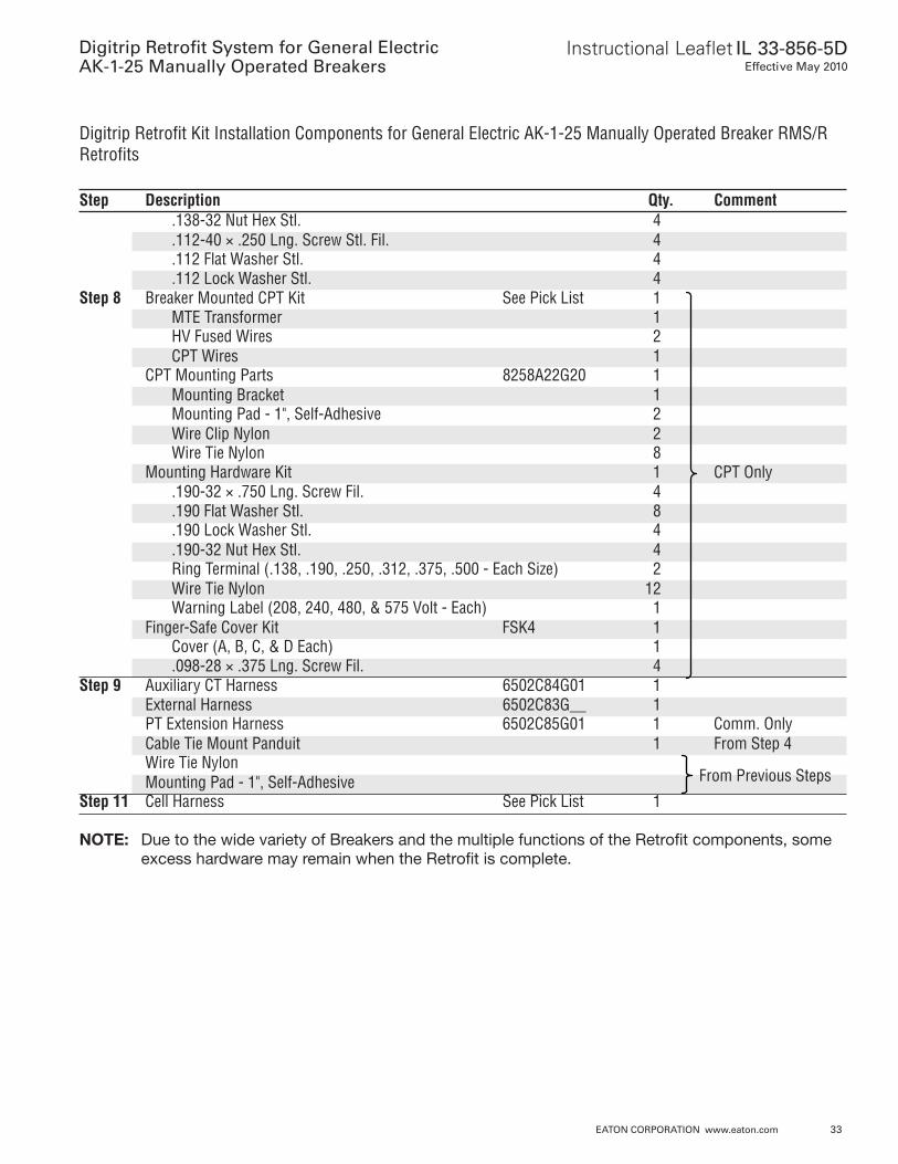
Step Description Qty. Comment.138-32 Nut Hex Stl. 4.112-40 × .250 Lng. Screw Stl. Fil. 4.112 Flat Washer Stl. 4.112 Lock Washer Stl. 4
Step 8 Breaker Mounted CPT Kit See Pick List 1MTE Transformer 1HV Fused Wires 2CPT Wires 1
CPT Mounting Parts 8258A22G20 1Mounting Bracket 1Mounting Pad - 1", Self-Adhesive 2Wire Clip Nylon 2Wire Tie Nylon 8
Mounting Hardware Kit 1 CPT Only.190-32 × .750 Lng. Screw Fil. 4.190 Flat Washer Stl. 8.190 Lock Washer Stl. 4.190-32 Nut Hex Stl. 4Ring Terminal (.138, .190, .250, .312, .375, .500 - Each Size) 2Wire Tie Nylon 12Warning Label (208, 240, 480, & 575 Volt - Each) 1
Finger-Safe Cover Kit FSK4 1Cover (A, B, C, & D Each) 1.098-28 × .375 Lng. Screw Fil. 4
Step 9 Auxiliary CT Harness 6502C84G01 1External Harness 6502C83G__ 1PT Extension Harness 6502C85G01 1 Comm. OnlyCable Tie Mount Panduit 1 From Step 4Wire Tie NylonMounting Pad - 1", Self-Adhesive
Step 11 Cell Harness See Pick List 1
NOTE: Due to the wide variety of Breakers and the multiple functions of the Retrofit components, someexcess hardware may remain when the Retrofit is complete.
From Previous Steps
Digitrip Retrofit System for General ElectricAK-1-25 Manually Operated Breakers
Instructional Leaflet IL 33-856-5DEffective May 2010
34 EATON CORPORATION www.eaton.com
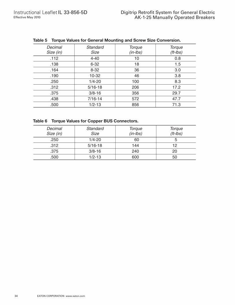
Decimal Standard Torque TorqueSize (in) Size (in-lbs) (ft-lbs)
.112 4-40 10 0.8
.138 6-32 18 1.5
.164 8-32 36 3.0
.190 10-32 46 3.8
.250 1/4-20 100 8.3
.312 5/16-18 206 17.2
.375 3/8-16 356 29.7
.438 7/16-14 572 47.7
.500 1/2-13 856 71.3
Decimal Standard Torque TorqueSize (in) Size (in-lbs) (ft-lbs)
.250 1/4-20 60 5
.312 5/16-18 144 12
.375 3/8-16 240 20
.500 1/2-13 600 50
Table 5 Torque Values for General Mounting and Screw Size Conversion.
Table 6 Torque Values for Copper BUS Connectors.
Instructional Leaflet IL 33-856-5DEffective May 2010
Digitrip Retrofit System for General ElectricAK-1-25 Manually Operated Breakers
EATON CORPORATION www.eaton.com 35
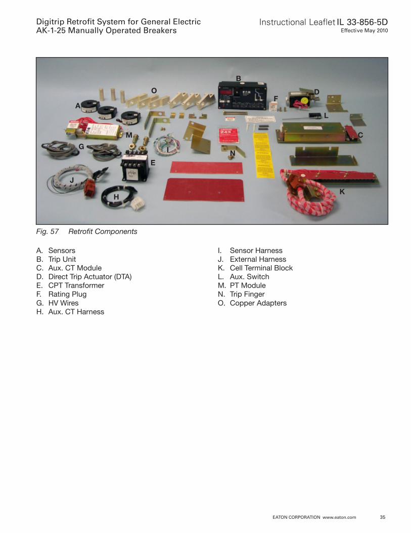
Fig. 57 Retrofit Components
A. SensorsB. Trip UnitC. Aux. CT ModuleD. Direct Trip Actuator (DTA)E. CPT TransformerF. Rating PlugG. HV WiresH. Aux. CT Harness
I. Sensor HarnessJ. External HarnessK. Cell Terminal BlockL. Aux. SwitchM. PT ModuleN. Trip FingerO. Copper Adapters
AL
H
G
C
E
D
B
I
J
F
K
M
N
O
Instruction Leaflet IL 33-856-5DEffective May 2010
Digitrip Retrofit System for General ElectricAK-1-25 Manually Operated Breakers
Eaton CorporationElectrical Group1000 Cherrington ParkwayMoon Township, PA 15108United States877-ETN-CARE (877-386-2273)Eaton .com
© 2010 Eaton CorporationAll Rights ReservedPrinted in USAPublication No . IL 33-856-5D / TBG000344Part No . IL33-856-5H04May 2010
PowerChain Management is a registered trademark of Eaton Corporation .
All other trademarks are property of their respective owners .
The instructions for installation, testing, maintenance, or repair herein are provided for the use of the product in general commercial applications and may not be appropriate for use in nuclear applica-tions . Additional instructions may be available upon specific request to replace, amend, or supplement these instructions to qualify them for use with the product in safety-related applications in a nuclear facility .
The information, recommendations, descriptions, and safety nota-tions in this document are based on Eaton’s experience and judg-ment with respect to Retrofitting of Power Breakers . This instruction-al literature is published solely for information purposes and should not be considered all-inclusive . If further information is required, you should consult an authorized Eaton sales representative .
The sale of the product shown in this literature is subject to the terms and conditions outlined in appropriate Eaton selling policies or other contractual agreement between the parties . This literature is not intended to and does not enlarge or add to any such contract . The sole source governing the rights and remedies of any purchaser of this equipment is the contract between the purchaser and Eaton .
NO WARRANTIES, EXPRESSED OR IMPLIED, INCLUDING WARRANTIES OF FITNESS FOR A PARTICULAR PURPOSE OR MERCHANTABILITY, OR WARRANTIES ARISING FROM COURSE OF DEALING OR USAGE OF TRADE, ARE MADE REGARDING THE INFORMATION, RECOMMENDATIONS, AND DESCRIPTIONS CONTAINED HEREIN. In no event will Eaton be responsible to the purchaser or user in contract, in tort (including negligence), strict liability or otherwise for any special, indirect, incidental or conse-quential damage or loss whatsoever, including but not limited to damage or loss of use of equipment, plant or power system, cost of capital, loss of power, additional expenses in the use of existing power facilities, or claims against the purchaser or user by its cus-tomers resulting from the use of the information, recommendations and description contained herein .


![Digitrip RMS 310 Electronic Circuit Breakers with Interchangeable … · 2015-07-16 · R-Frame January 2001 Vol. 1, Ref. No. [0568] Digitrip RMS 310 Electronic Circuit Breakers with](https://static.documents.pub/doc/80x56/5b3eea737f8b9a91078b7836/digitrip-rms-310-electronic-circuit-breakers-with-interchangeable-2015-07-16.jpg)


