Effective October, 2000 IL 33-G2C-2 SAFETY PRECAUTIONS POWER CIRCUIT BREAKERS ARE EQUIPPED WITH HIGH SPEED, HIGH ENERGY OPERATING MECHANISMS. THE BREAKERS AND THEIR ENCLOSURES ARE DESIGNED WITH SEVERAL BUILT-IN INTERLOCKS AND SAFETY FEATURES INTENDED TO PROVIDE SAFE AND PROPER OPERATING SEQUENCES. TO PRO- VIDE MAXIMUM PROTECTION FOR PERSON- NEL ASSOCIATED WITH THE INSTALLATION, OPERATION, AND MAINTENANCE OF THESE BREAKERS, THE FOLLOWING PRACTICES MUST BE FOLLOWED. FAILURE TO FOLLOW THESE PRACTICES MAY RESULT IN DEATH, PERSONAL INJURY, OR PROPERTY DAMAGE. • Only qualified persons, as defined in the National Electric Code, who are familiar with the installa- tion and maintenance of power circuit breakers and their associated switchgear assemblies should perform any work associated with these breakers. Digitrip Retrofit System for the General Electric AK-50 Series Breakers: AK-1-50 (Frameless); AK-2-50; AK-2A-50; AKT-2A-50; AKU-2A-50; AK-3-50; AK-3A-50; and AKT-3A-50 • Completely read and understand all instructions before attempting any installation, operation, maintenance, or modification of these breakers. • Always turn off and lock out the power source feeding the breaker prior to attempting any installation, maintenance, or modification of the breaker. Do not use the circuit breaker as the sole means for isolating a high voltage circuit. Follow all lockout and tagging rules of the National Electric Code and all other applicable codes, regulations, and work rules. • Do not work on a closed breaker or a breaker with the closing springs charged. Trip (open) the breaker and be sure the stored energy springs are discharged before performing any work. The breaker may trip open or the charging springs may discharge, causing crushing or cutting injuries. • For drawout breakers, trip (open), and then remove the breaker to a well-lit work area before beginning work. • Do not perform any maintenance: including breaker charging, closing, tripping, or any other function which could cause significant movement of the breaker while it is on the extension rails. Doing so may cause the breaker to slip from the rails and fall, potentially causing severe personal injury to those in the vicinity. • Do not leave the breaker in an intermediate position in the switchgear cell. Always leave it in the connected, disconnected, or (optional) test position. Failure to do so could lead to improper positioning of the breaker and flashover, causing death, serious personal injury, and / or property damage. • Do not defeat any safety interlock. Such interlocks are intended to protect personnel and equipment from damage due to flashover and exposed contacts. Defeating an interlock could lead to death, severe personal injury, and / or property damage. WARNING
Transcript
Effective October, 2000
IL 33-G2C-2
SAFETY PRECAUTIONS
POWER CIRCUIT BREAKERS ARE EQUIPPEDWITH HIGH SPEED, HIGH ENERGY OPERATINGMECHANISMS. THE BREAKERS AND THEIRENCLOSURES ARE DESIGNED WITH SEVERALBUILT-IN INTERLOCKS AND SAFETYFEATURES INTENDED TO PROVIDE SAFE ANDPROPER OPERATING SEQUENCES. TO PRO-VIDE MAXIMUM PROTECTION FOR PERSON-NEL ASSOCIATED WITH THE INSTALLATION,OPERATION, AND MAINTENANCE OF THESEBREAKERS, THE FOLLOWING PRACTICESMUST BE FOLLOWED. FAILURE TO FOLLOWTHESE PRACTICES MAY RESULT IN DEATH,PERSONAL INJURY, OR PROPERTY DAMAGE.
• Only qualified persons, as defined in the NationalElectric Code, who are familiar with the installa-tion and maintenance of power circuit breakersand their associated switchgear assembliesshould perform any work associated with thesebreakers.
Digitrip Retrofit System for the General Electric AK-50 Series Breakers:AK-1-50 (Frameless); AK-2-50; AK-2A-50; AKT-2A-50; AKU-2A-50;
AK-3-50; AK-3A-50; and AKT-3A-50• Completely read and understand all instructions
before attempting any installation, operation,maintenance, or modification of these breakers.
• Always turn off and lock out the power sourcefeeding the breaker prior to attempting anyinstallation, maintenance, or modification ofthe breaker. Do not use the circuit breaker asthe sole means for isolating a high voltagecircuit. Follow all lockout and tagging rules ofthe National Electric Code and all otherapplicable codes, regulations, and work rules.
• Do not work on a closed breaker or a breakerwith the closing springs charged. Trip (open) thebreaker and be sure the stored energy springsare discharged before performing any work. Thebreaker may trip open or the charging springsmay discharge, causing crushing or cuttinginjuries.
• For drawout breakers, trip (open), and thenremove the breaker to a well-lit work area beforebeginning work.
• Do not perform any maintenance: includingbreaker charging, closing, tripping, or any otherfunction which could cause significant movementof the breaker while it is on the extension rails.Doing so may cause the breaker to slip from therails and fall, potentially causing severe personalinjury to those in the vicinity.
• Do not leave the breaker in an intermediateposition in the switchgear cell. Always leave itin the connected, disconnected, or(optional) test position. Failure to do socould lead to improper positioning of thebreaker and flashover, causing death, seriouspersonal injury, and / or property damage.
• Do not defeat any safety interlock. Suchinterlocks are intended to protect personneland equipment from damage due to flashoverand exposed contacts. Defeating an interlockcould lead to death, severe personal injury,and / or property damage.
WARNING
Effective October, 2000
IL 33-G2C-2Page 2
Cutler-Hammer Digitrip Retrofit Kits are available ina number of configurations that provide a widerange of features. The Digitrip System starts withthe 510 Basic Kit which offers true RMS sensing,overcurrent protection, and self-testing features.Advanced Digitrip Retrofit Kits feature zoneinterlocking, digital alphanumeric displays, remotealarm signals, IMPACC communications, energymonitoring capabilities, power factors, andharmonic content measurements.
The following table provides a quick reference ofthe components supplied with each level of RetrofitKit. Before beginning the Retrofit process, take aminute to review the information contained in thetable. It is important that the Retrofitter understand
which level of Retrofit Kit is to be installed andwhich components are included with the Kit.
The instructions contained in this manual cover theinstallation of all levels of Retrofit Kit. If the Kit youare installing does not contain a certain component,skip the instructions for that component andproceed to the next.
Throughout the Retrofit process, refer to the TorqueTables at the back of this manual forspecific torque values.
If you have any questions concerning the RetrofitKit and / or the Retrofit process, contactCutler-Hammer at 1-800-937-5487.
Beginning the Retrofit ProcessIdentifying the Breaker and the Retrofit Kit
Before beginning the Retrofit Process, it isimportant to verify exactly which version ofG. E. AK-50 Series Breaker(s) is to be Retrofittedand to insure that the correct Cutler-HammerRetrofit Kit(s) was ordered. Each Breaker must beidentified using all of the following sources that areapplicable:
1. Nameplate Information;2. Breaker Rating;3. Framed or Frameless;4. Fused or Non-Fused; and if fused5. Location of Fuses
(on Top or Bottom Breaker Stabs).
Please refer to the following chart and verify thatthe first three (3) characters of the Digitrip RetrofitKit Code Number correspond to the Breaker beingRetrofitted. If you find that the Retrofit Kit does notmatch the Breaker, do not attempt the Retrofit.Contact your purchasing agent and have thecorrect Retrofit Kit ordered for the Breaker.
Following the Icons to a Successful Retrofit
During certain parts of the Retrofit Process,procedures may differ depending on the versionof the Breaker being Retrofitted. To enable theRetrofitter to quickly identify the correct proceduresfor the Breaker, the following Icon System hasbeen developed. As you are working through aprocedure and the Icons appear, simply followonly the instructions identified by the Icon for theBreaker being Retrofitted.
Before attempting to remove the Breaker from theCell or perform any Retrofit Operation, be sureto read and understand the Safety Precautionssection of this manual. In addition, be sure to readand understand the Instructions for the Applicationof Digitrip RMS Retrofit Kits on Power CircuitBreakers (Retrofit Application Data - PublicationAD 33-855-1), supplied with the Digitrip Retrofit Kit.
NOTE: For Breakers Utilizing a RemotelyMounted Neutral Sensor Connected to theBreaker via Neutral CT Disconnect Only. Therating of the Neutral CT Disconnect, originallysupplied with the Breaker, does not meet thespecifications / requirements of the Retrofit Kit.The Neutral CT Disconnect must be removedand scrapped. The remotely mounted fourthSensor must be wired into the system viaSecondary Disconnects.
If the Breaker being Retrofitted is NOTequipped with Secondary Disconnects, theSecondary Disconnects for both the Breakerand the Cell, as well as all mounting bracketsand hardware, must be secured from theoriginal manufacturer of the Breaker BEFOREbeginning the Retrofit Process.
DO NOT ATTEMPT TO INSTALL OR PERFORMMAINTENANCE ON EQUIPMENT WHILE IT ISENERGIZED. SEVERE PERSONAL INJURY ORDEATH CAN RESULT FROM CONTACT WITHENERGIZED EQUIPMENT. VERIFY THAT NOVOLTAGE IS PRESENT BEFORE PROCEEDING.
A. Trip the Breaker and remove it from the Cell.Move the Breaker to a clean, well-lit workbench.
NOTE: It is the responsibility of the Retrofitterto insure that the Breaker and all original com-ponents are in good condition. Visually inspectall Breaker components for signs of damage orwear. If any signs of damage or wear aredetected for components not included in theRetrofit Kit, secure the necessary replacementparts before beginning the Retrofit Process.
The force necessary to trip the Breaker shouldnot exceed three (3) lbs.
To begin the Retrofit Process, refer to the compo-nents list at the end of this manual. Lay out thecomponents and hardware according to the stepsoutlined. The components and hardware will beused to complete each step in the Retrofit Process.
NOTE: For most photographs contained withinthis manual, a G. E. AK-2-50 Breaker was usedas the subject. Depending on the version andage of the Breaker being Retrofitted, somecomponents / views depicted in this manualmay differ from the Breaker being Retrofitted.
WARNING
Effective October, 2000
IL 33-G2C-2 Page 5
Step 2: Removing the OriginalElectromechanical Trip Units
For All G. E. AK-50 Series Breakers ExceptAK-3/3A-50, AKU-3/3A-50, and BreakersEquipped with a Quick Close Mechanism.
Follow the G. E. AK-50 Series Instruction Manual,originally supplied with the Breaker, to perform thefollowing procedures.
A. Carefully lay the Breaker over on its right side toprovide access to the bottom of the Breaker.
B. Remove and scrap the originalElectromechanical Trip Units and mountinghardware from each phase.
C. Remove and scrap the Electromechanical TripPaddles and mounting hardware from theBreaker Trip Bar.
For G. E. AK-3/3A-50, AKU-3/3A-50, and BreakersEquipped with a Quick Close Mechanism Only.
Follow the G. E. AK-3/3A-50 Series InstructionManual, originally supplied with the Breaker, toperform the following procedures.
A. Carefully lay the Breaker over on its right side toprovide access to the bottom of the Breaker.
B. Disconnect and scrap all wires connectingthe original Electronic Trip Units, Direct TripActuator, and the original Sensors mountedon the bottom studs.
C. Remove and scrap the original Sensors,Electronic Trip Units, Direct Trip Actuator,Reset Links, and all associated mountinghardware.
Note: For Breakers originally fitted with aremotely mounted Neutral Sensor, theNeutral CT Disconnect must be removedand discarded.
Effective October, 2000
IL 33-G2C-2Page 6
Step 3: Installing the Copper Adapters
A. Align the holes in the Copper Adapters with theholes that were used to mount the originalElectromechanical Trip Units.
B. Mount a Copper Adapter to each Phase, asshown, using the (12) .375-16 × 1.50" bolts,(12) lock washers, and (12) flat washerssupplied.
For Kits Supplied with a PT Module Only.
As viewed from the front of the Breaker, do notinstall the left mounting bolt in each CopperAdapter. These will be used later in the RetrofitProcess to attach the PT Wires to each PhaseFrame.
C. Carefully return the Breaker to the uprightposition.
Before proceeding, identify the section(s) withinthe Step that apply to the Breaker beingRetrofitted.
Step 4: Installing the Sensors
Note: On Breakers equipped with a RackingMechanism, the Sensors and Sensor MountingBracket provide adequate clearance betweenthe Sensors and Racking Mechanism.
Effective October, 2000
IL 33-G2C-2 Page 7
For Top Mounted Sensors Only.
A. Align a 3-Point Terminal Block with each setof holes in the Sensor Mounting Bracket asshown. Secure the 3-Point Terminal Blocks tothe Sensor Mounting Bracket using the(6) .138-32 × .500" screws and (6) lockwashers supplied.
B. Install a Flexiform Grommet to the edges ofeach wire cutout in the Sensor MountingBracket.
C. Insert the three (3) wires exiting the top of theSensor through the opening in the SensorMounting Bracket.
D. With the Sensor Nameplate at the top andfacing out, align the threaded holes in the topof the Sensor with the holes in the SensorMounting Bracket. Secure the Sensor to theSensor Mounting Bracket using the (4).250-20 × .500" bolts, (4) lock washers, and(4) flat washers supplied.
E. Repeat Steps B and C for the remainingtwo (2) Sensors.
F. Connection of the Sensor Wires to the 3-PointTerminal blocks is detailed in the photo. Oncethe correct connection point has beendetermined, cut each Sensor Wire to anappropriate length and attach a supplied ringterminal to each wire.
G. Align the Sensor Mounting Bracket / SensorAssembly with the existing holes on the top rearof the Breaker Back Plate as shown. Secureusing the (2) .500-13 × 1.50" bolts, (4) flatwashers, (2) lock washers, and (2) nutssupplied.
Black RedWhite
Black
WhiteRed
Effective October, 2000
IL 33-G2C-2Page 8
For Bottom Mounted Sensors Only.
A. Following the G. E. AK-50 Series InstructionManual originally supplied with the Breaker,remove and save the fuses, mounting brackets,and hardware.
B. Again following the G. E. AK-50 SeriesInstruction Manual, remove and save thehardware that secures the .750" thick SupportPlate to the Breaker Back Plate. Remove andscrap the Support Plate.
C. Align the holes in the new Glass Poly SupportPlate with the holes in the Breaker Plate. Notethat the cutout for the Sensors must face thebottom of the Breaker. Secure the new SupportPlate using the original mounting hardware.
D. Align a 3-Point Terminal Block with each setof holes in the Sensor Mounting Bracket asshown. Secure the 3-Point Terminal Blocksto the Sensor Mounting Bracket using the(6) .138-32 × .500" screws, (12) flat washers,(6) lock washers, and (6) nuts supplied.
E. Install a Flexiform Grommet to the edges ofeach wire cutout in the Sensor MountingBracket.
F. Insert the three (3) wires exiting the top of theSensor through the opening in the SensorMounting Bracket.
G. With the Sensor Nameplate at the bottom andfacing out, align the threaded holes in the topof the Sensor with the holes in the SensorMounting Bracket. Secure the Sensor to theSensor Mounting Bracket using the (4).250-20 × .500" bolts, (4) lock washers, and(4) flat washers supplied.
H. Repeat Steps E and F for the remaining two(2) Sensors.
I. Connection of the Sensor Wires to the 3-PointTerminal blocks is detailed in the photo. Oncethe correct connection point has beendetermined, each Sensor Wire should be cut toan appropriate length and a supplied ringterminal attached to each.
Black RedWhite
Black
WhiteRed
Effective October, 2000
IL 33-G2C-2 Page 9
J. Align the Sensor Mounting Bracket with theexisting holes on the bottom rear of the BreakerBack Plate as shown. Secure using the (2).500-13 × 1.50" bolts, (4) flat washers, (2) lockwashers, and (2) nuts supplied.
K. Following the G. E. AK-50 Series InstructionManual originally supplied with the Breaker,reinstall the original fuses, mounting brackets,and hardware.
For AKT-2A-50 and AKT-3A-50 2,000 AmpBreakers Only.
A. Align two (2) Sensor Adapter Brackets withthe holes in the top of the Sensor as shown(the Sensor Terminals are located on thebottom of the Sensor). Secure the SensorAdapter Brackets to the Sensor using the (2).250-20 × 2.75" bolts, (4) flat washers, (2) lockwashers, and (2) nuts supplied.
B. Repeat Step A for the remaining two (2)Sensors.
C. Align the threaded holes in the SensorAdapter Brackets with the holes in the SensorMounting Bracket. Secure the Sensor Assemblyto the Sensor Mounting Bracket using the (4).250-20 × .500" bolts, (2) lock washers, and (2)flat washers supplied.
D. Repeat Step B for the remaining two (2)Sensor Assemblies.
E. Align the Sensor Mounting Bracket / SensorAssembly with the existing holes on the toprear of the Breaker Back Plate as shown.Secure using the (2) .500-13 × 1.50" bolts,(4) flat washers, (2) lock washers, and (2)nuts supplied.
Effective October, 2000
IL 33-G2C-2Page 10
Step 5: Installing the Aux. CT Module
A. Carefully lay the Breaker over on its left side.
B. Using Drilling Plan “A”, drill four (4) .219"diameter holes near the bottom of the right sideof the Breaker. Note that the positioning of theAux. CT Module differs slightly for Breakersequipped with a Quick Close Mechanism.
Note: Cover the region below the area tobe drilled to prevent chips from falling intothe Breaker.
C. Remove the screws installed in the right side ofthe Aux. CT Module.
D. Align the holes in the right side of the Aux. CTModule with the holes just drilled in the rightside of the Breaker. Secure the Aux. CT Moduleto the Breaker using the (4) .190-16 × .500"thread cutting screws, (4) flat washers, and(4) lock washers supplied.
AK Breaker A B
Without Quick Close Mech. 6.62 0.75
With Quick Close Mech. 4.38 1.00
Drilling Plan “A”
1.38" 1.38" Rear of Breaker
0.219 Dia. (4)
B
1.50"
0.75"0.75"
A
Effective October, 2000
IL 33-G2C-2 Page 11
Before proceeding, identify the section(s) withinthe Step that apply to the Breaker beingRetrofitted.
Step 6: Installing the Sensor Harness and DTAExtension Harness
A. Connect the Sensor Harness to the properterminals on the Aux. CT Module. Refer toSection 12 of the Retrofit Application Data,supplied with the Retrofit Kit, for detailed wiringspecifications.
B. Using one of the screws from Step 5, connectthe green ground wire from the Sensor Harness(with ring terminal) to the Aux. CT Module.
Note: The long tan and green wires are forthe Remote Neutral Sensor on a 4W GroundBreaker. They should be removed if notrequired for the Retrofit.
C. Install the supplied grommet in the hole nearthe bottom right corner of the Breaker BackPlate.
D. Route the Sensor Harness towards the rightrear of the Breaker and through the grommetjust installed.
E. Route the Sensor Harness along the right rearof the Breaker Back Plate up to the Sensors.
Connect the ring terminals of the SensorHarness to the 3-Point Sensor Terminal Blocks.Refer to Section 12 of the Retrofit ApplicationData, supplied with the Retrofit Kit, for detailedwiring specifications.
Effective October, 2000
IL 33-G2C-2Page 12
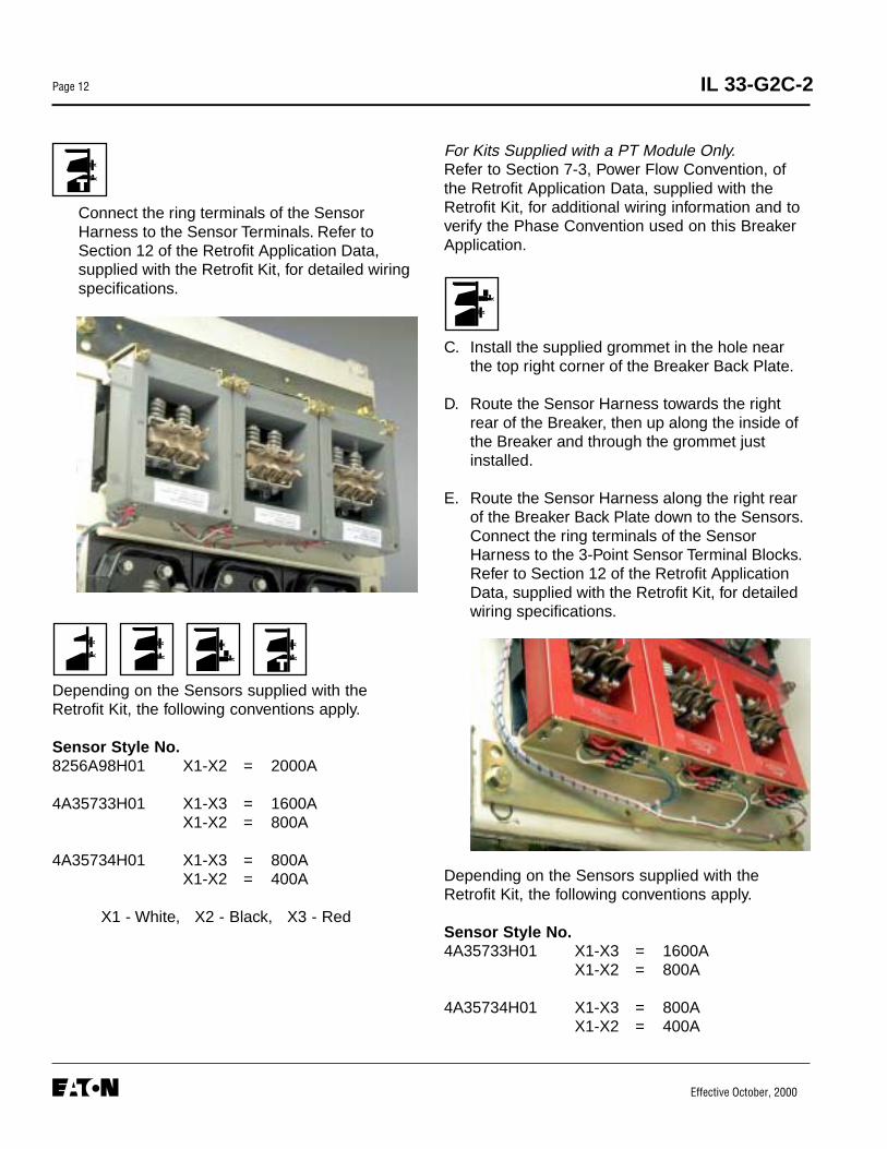
Connect the ring terminals of the SensorHarness to the Sensor Terminals. Refer toSection 12 of the Retrofit Application Data,supplied with the Retrofit Kit, for detailed wiringspecifications.
Depending on the Sensors supplied with theRetrofit Kit, the following conventions apply.
Sensor Style No.8256A98H01 X1-X2 = 2000A
4A35733H01 X1-X3 = 1600AX1-X2 = 800A
4A35734H01 X1-X3 = 800AX1-X2 = 400A
X1 - White, X2 - Black, X3 - Red
For Kits Supplied with a PT Module Only.Refer to Section 7-3, Power Flow Convention, ofthe Retrofit Application Data, supplied with theRetrofit Kit, for additional wiring information and toverify the Phase Convention used on this BreakerApplication.
C. Install the supplied grommet in the hole nearthe top right corner of the Breaker Back Plate.
D. Route the Sensor Harness towards the rightrear of the Breaker, then up along the inside ofthe Breaker and through the grommet justinstalled.
E. Route the Sensor Harness along the right rearof the Breaker Back Plate down to the Sensors.Connect the ring terminals of the SensorHarness to the 3-Point Sensor Terminal Blocks.Refer to Section 12 of the Retrofit ApplicationData, supplied with the Retrofit Kit, for detailedwiring specifications.
Depending on the Sensors supplied with theRetrofit Kit, the following conventions apply.
Sensor Style No.4A35733H01 X1-X3 = 1600A
X1-X2 = 800A
4A35734H01 X1-X3 = 800AX1-X2 = 400A
Effective October, 2000
IL 33-G2C-2 Page 13
For Kits Supplied with a PT Module Only.Refer to Section 7-3, Power Flow Convention, ofthe Retrofit Application Data, supplied with theRetrofit Kit, for additional wiring information and toverify the Phase Convention used on this BreakerApplication.
F. Connect the “+” wire of the DTA ExtensionHarness to the “OP” terminal of the Aux. CTModule and the unmarked wire to the “ON”terminal. Route the DTA Extension Harnessinside the Breaker towards the left front corner.
G. Use the nylon wire ties and clamps supplied todress all wires to keep them away from anymoving parts within the Breaker.
H. Carefully return the Breaker to its normal,upright position.
Step 7: Installing the DTA Assembly
A. With the Breaker in the OPEN position and withthe Breaker Closing Springs DISCHARGED,mount the Trip Finger on the Breaker Trip Bar,as shown, using the (1) .250-20 × .750"carriage bolt, (1) flat washer, (1) lock washer,and (1) nut supplied. Do not tighten hardware atthis time. The Trip Finger should be free to moveon the Trip Bar.
Effective October, 2000
IL 33-G2C-2Page 14
E. With the Breaker in the OPEN position and withthe Breaker Closing Springs DISCHARGED,slide the Trip Finger (attached to the BreakerTrip Bar in Step 7-A) over so that it is locatedunder the left hand side of the DTA flange nut.
F. Position trip finger with a HORIZONTAL GAP of0.03" to 0.12" to the DTA shaft.
G. Tighten trip finger mounting hardware. Recheckhorizontal gap and reposition the Trip Finger ifnecessary.
H. Verify DTA Assembly is reset. Manually reset ifnecessary.
DO NOT apply more than 5 lbs. force to the endof the Reset Spring when manually resetting.Excessive force can bend the springs, resultingin a failure of the DTA Assembly to reset duringnormal operation.
I. Close the breaker.
B. Position the DTA Assembly near the front of theBreaker. Route the DTA Extension Harnessfrom the Aux. CT Module under the front of theBreaker to the 2-Point Terminal Block mountedon the DTA Assembly. Connect the “+” wire ofthe DTA Extension Harness to the sameterminal as the DTA Wire marked “+”. Connectthe unmarked wire of the DTA ExtensionHarness to the same terminal as the unmarkedDTA Wire.
C. Carefully tilt the Breaker back and slide the DTAAssembly under the front of the Breaker.Position the DTA Assembly near the left front ofthe Breaker with the 2-Point Terminal Blockfacing the rear of the Breaker. Lower the front ofthe Breaker, being careful not to damage theDTA Assembly.
D. Align the DTA Assembly with the existing holesnear the bottom front of the Left Breaker Frame.Apply Loc-Tite® 242 to the threads then securethe DTA Assembly, as shown, using the (2).375-16 × 1.00" bolts, (4) flat washers, (2) lockwashers, and (2) nuts supplied.
Note: On some breakers, a Ground Shoe mayhave been mounted to the holes used tomount the DTA Assembly. When mounting theDTA Assembly, the Ground Shoe MUST BEreinstalled and secured to the Breaker usingthe ORGINAL mounting hardware.
WARNING
HORIZONTALGAP
HORIZONTALGAP
Effective October, 2000
IL 33-G2C-2 Page 15
Guard against the Breaker unintentionallyOPENING during the following steps. Keephands and fingers away from the BreakerCrossbar.
J. Manually raise the DTA Assembly Reset Springuntil DTA flange nut touches Trip Finger.Measure this movement at the end of the DTAreset spring. The movement should be withinthe range of 0.19" to 0.56". This corresponds toa VERTICAL GAP of 0.06" and 0.19" from theTrip Finger to the DTA flange nut.
K. Verify DTA trips the Breaker by applying24 VDC to DTA terminals.
L. With Breaker in the OPEN position, remove theoriginal .375-16 × 1.50" hex bolt from the lefthand side of the Breaker Cross Bar. Mount theDTA Reset Arm to the Cross Bar with the boltjust removed. After tightening, be sure to lockthe bolt head with the locking clip.
M. Cycle the Breaker five (5) times (closing theBreaker then tripping with the DTA per Step K),verifying reliable tripping of the Breaker.
WARNING
1. Trip Actuator2. Trip Finger3. Flange Nut4. Trip Shaft Lever
1
3
2
VERTICALGAP
4
Effective October, 2000
IL 33-G2C-2Page 16
Before proceeding, identify the section(s) withinthe Step that apply to the Breaker beingRetrofitted.
Step 8: Installing the Breaker Mounted CPT
A. Align the CPT with the holes in the CPTMounting Bracket as shown. Secure the CPTto the mounting bracket using the (4).190-32 × .500" screws, (8) flat washers,(4) lock washers, and (4) nuts supplied.
B. Align the Glass Ploy Insulation with the holes inthe CPT Mounting Bracket as shown. Securethe CPT to the mounting bracket using the (2).190-32 × .625" nylon screws, (2) nylon flatwashers, (2) steel flat washers, (2) lockwashers, and (2) nuts supplied. Note that thescrews are inserted thorough the Glass PolyInsulation first and then through the CPTMounting Bracket. The nylon flat washersMUST BE used between the screw head andthe Glass Poly Insulation.
Effective October, 2000
IL 33-G2C-2 Page 17
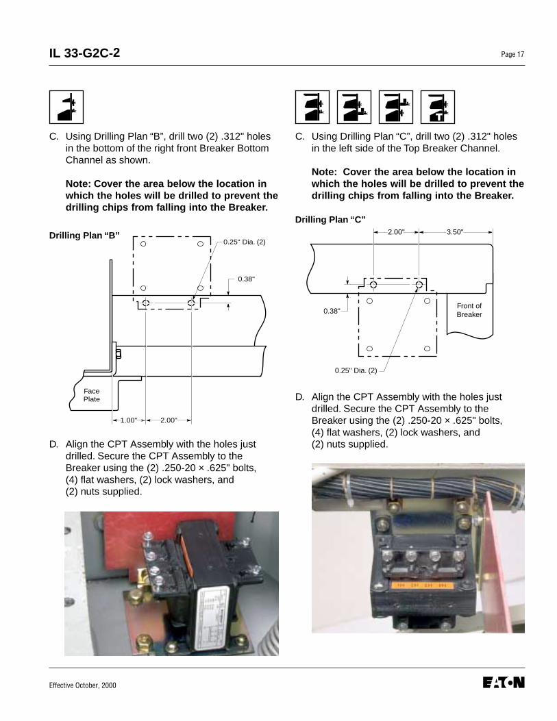
C. Using Drilling Plan “B”, drill two (2) .312" holesin the bottom of the right front Breaker BottomChannel as shown.
Note: Cover the area below the location inwhich the holes will be drilled to prevent thedrilling chips from falling into the Breaker.
D. Align the CPT Assembly with the holes justdrilled. Secure the CPT Assembly to theBreaker using the (2) .250-20 × .625" bolts,(4) flat washers, (2) lock washers, and(2) nuts supplied.
C. Using Drilling Plan “C”, drill two (2) .312" holesin the left side of the Top Breaker Channel.
Note: Cover the area below the location inwhich the holes will be drilled to prevent thedrilling chips from falling into the Breaker.
D. Align the CPT Assembly with the holes justdrilled. Secure the CPT Assembly to theBreaker using the (2) .250-20 × .625" bolts,(4) flat washers, (2) lock washers, and(2) nuts supplied.
1.00"
0.38"
0.25" Dia. (2)
2.00"
Right Front BreakerBottom Mounting
Channel
Face Plate
Drilling Plan “B”
0.25" Dia. (2)
3.50"
Front ofBreaker
2.00"
0.38"
Drilling Plan “C”
Effective October, 2000
IL 33-G2C-2Page 18
Before proceeding, identify the section(s) withinthe Step that apply to the Breaker beingRetrofitted.
Step 9: Installing the Trip Unit
A. Using Drilling Plan “D”, mark and drill two(2) .312" diameter holes in the top flange ofthe bottom right Breaker Channel.
Note: Cover the area below the location inwhich the holes will be drilled to prevent thedrilling chips from falling into the Breaker.
A. Using Drilling Plan “E”, mark and drill two (2).312" diameter holes in the right side of themiddle Breaker Channel.
Note: Cover the area below the location inwhich the holes will be drilled to prevent thedrilling chips from falling into the Breaker.
Framed
Frameless
2.75"
0.81"
3.38"
Right Front BreakerBottom Mounting Channel
0.312" Dia. (2)
Face Plate
Drilling Plan “D” 4.75"
Top
Front
4.00"
2.38"
0.312" Dia. (2)
Main Spring BarSlotted Side Hole
Drilling Plan “E”
Effective October, 2000
IL 33-G2C-2 Page 19
B. Mount the left-hand (the larger Bracket withcut-out) and right-hand Trip Unit MountingBrackets, as shown, to the Glass Poly Barrierusing the (2) .190-32 × .500" steel screws,(2) .190-32 × .625" nylon screws, (6) steelflat washers, (2) nylon flat washers, (4) lockwashers, and (4) nuts supplied.
Note: The nylon screws and flat washersare to be used in the top holes and thesteel screws and flat washers are to beused in the bottom holes. The screw headsmust be on the Glass Poly Barrier side ofthe assembly.
C. For Kits Supplied with an Auxiliary Switch Only.Using a pair of diagonals, cut 4" off the end ofthe Microswitch Arm. Mount the Microswitch tothe Auxiliary Switch Mounting Bracket, asshown, using the (2) .138-32 × 1.00" screws,(4) flat washers, (2) lock washers, and (2) nutssupplied.
Note: The orientation of the Microswitch isdifferent for the Frameless versus theFramed Breakers.
Mount the Auxiliary Switch Assembly to thebottom of the right-hand Trip Unit MountingBracket Assembly, using the (1) .138-32 × .375"screw, (2) flat washers, (1) lock washer, and (1)nut supplied.
D. For Kits Supplied with a PT Module Only.Remove the “L” Mounting Bracket, WarningLabel Plate, and Connector from the PotentialTransformer (PT) Module.
Using the original hardware, reconnect the “L”Mounting Bracket, New Warning Label Plate,and the Connector to the side of the PT Moduleas shown.
Effective October, 2000
IL 33-G2C-2Page 20
Scrap the Warning Label Plate and “L” Bracket.Rotate the connector 90° then reconnect it tothe PT Module, as shown, using the originalhardware.
Mount the PT Module to the right-hand Trip UnitMounting Bracket, using the (2) .138-32 × .375"screws, (2) flat washers, and (2) lock washerssupplied. The Glass Poly Insulation Barrier mustbe positioned between the PT Module and theTrip Unit Mounting Bracket.
E. Mount the Trip Unit to the Trip Unit MountingBracket Assembly, as shown, using the (4)Brass Spacers, (2) .190-32 × 5.00" screws,(4) flat washers, (2) lock washers, and(2) nuts supplied.
F. Align the holes in the “L” shaped Trip UnitMounting Bracket with the holes drilled in theBreaker Channel in the applicable Step 8-A.Secure the Mounting Bracket to the BreakerChannel using the (2) .250-20 × 1.00" bolts, (4)flat washers, (2) lock washers, and (2) nutssupplied.
Mount the Trip Unit Assembly to the pre-drilledholes in the top of the “L” shaped Trip UnitMounting Bracket, installed in Step 8-B, usingthe (2) .250-20 × .750" bolts, (4) flat washers,(2) lock washers, and (2) nuts supplied.
F. Align the holes in the Trip Unit Assembly withthe holes drilled in the right side of the middleBreaker Channel in the applicable Step 8-A.Secure the Trip Unit Assembly to the BreakerChannel using the (2) .250-20 × .750" bolts, (4)flat washers, (2) lock washers, and (2) nutssupplied.
Effective October, 2000
IL 33-G2C-2 Page 21
For Kits Supplied with a PT Module Only.Install the supplied PT Module Warning Labelto the top right of the Breaker in front of thePT Module.
G. Remove Trip Unit Cover and install the RatingPlug. Replace the cover.
Before proceeding, identify the section(s) withinthe Step that apply to the Breaker beingRetrofitted.
Step 10: Connecting the CPT to theBreaker Stabs
A. Position the fuses in an accessible locationthen mark and cut the Load Side of each HighVoltage Fused Wire (HV Wire). Strip .250" fromeach Load Side HV Wire and attach a .138" ringterminal to each. Attach the HV Wires to theCPT terminals to achieve the required voltage.(See the following Table.)
Voltage Required CPT Terminals Used
480 Volt Circuit H1 & H4240 Volt Circuit H1 & H3208 Volt Circuit H1 & H2
NOTE: The power convention of the AK-50Series Breakers is normally Top to Bottom,meaning the Top Breaker Stabs are on theLine Side of the Breaker and the BottomBreaker Stabs are on the Load Side.
The HV Wires from the CPT MUST BEATTACHED to the Line Side of the Breaker.If it is determined that the power flow for theBreaker application is opposite the normalconvention, the HV Wires must be attachedto the Bottom Breaker Stabs.
B. Route the HV Wires towards the back of theBreaker, over the Backplate, then down towardsthe appropriate Breaker Stabs (Phase 1 and 2,or 2 and 3).
NOTE: The Line Side HV Wires are longerthan necessary and are cut during the fol-lowing steps. Before cutting the wires, besure that sufficient length is left so that theHV Wire Fuses are accessible from the topof the Breaker and that the connections canbe made to the correct Breaker Stabs.
C. Drill a .172" hole in the appropriate BreakerStabs. Tap each hole using a .190-32bottom tap.
NOTE: For GUC Breakers Only.Additional holes do not have to be drilledand tapped in the Breaker Stabs to connectthe HV Wires. The hardware securing thefuses to the Stabs can be used to connectthe HV Wires.
D. Cut the HV Wires to the appropriate length forattachment to the appropriate Phase. Strip.250" from each HV Wire and attach a .190"ring terminal. Connect the HV Wires to theBreaker Stabs using the (2) .190-32 × .500"screws, (2) lock washers, and (2) flat washerssupplied.
Effective October, 2000
IL 33-G2C-2Page 22
E. For Kits Supplied with a Breaker MountedCPT Only. Remove the External Harness pluginstalled in the bottom rear socket on the rightside of the Trip Unit. Insert the black plug of theCPT Harness into the same socket. Reinsertthe External Harness plug just removed into thefemale receptacle on the CPT Harness.
Route the two (2) wires of the CPT Harness tothe X1 and X2 terminals of the CPT. Assure thatthe wires are clear of any moving parts withinthe Breaker.
Cut the wires to length. Strip .250" of insulationand attach a .138" ring terminal to each wire.Connect the wires to the X1 and X2 terminalsof the CPT.
F. Use the nylon wire ties provided to dress theHV Wires and keep them away from any movingparts within the Breaker.
G. Attach the appropriate label for the Breaker tothe Breaker Cover in a clearly visible position.Three (3) labels are included with the CPT, one(1) for 480 Volt, one (1) for 240 Volt, and one (1)for 208 Volt systems.
Before proceeding, identify the section(s) withinthe Step that apply to the Breaker beingRetrofitted.
Step 11: Final Connection of the Harnessesand Wiring
A. For Kits Supplied with a PT Module Only.Route the PT Wires down through the Breakerto the Copper Adapters installed in Step 3.Route them so that they are clear of all movingparts within the Breaker.
The PT Wires are marked for connection toPhases 1, 2, and 3 with correspondingnumbers.
NOTE: Before cutting the PT Wires, verifythe Phase Convention used on the BreakerApplication.
FramedFrameless
Effective October, 2000
IL 33-G2C-2 Page 23
D. Secure the External Harness to the Trip Unit “L”shaped Mounting Bracket, as shown, using the(2) nylon wire clamps and the (2) .138 × .380"thread cutting screws supplied.
D. Drill two (2) .164" holes in the right side of theBreaker Frame. Secure the External Harness tothe holes just drilled using the (2) nylon wireclamps and the (2) .138 × .380" thread cuttingscrews supplied.
Route the PT Wires to a position suitable forattachment to the proper Copper Adapters.Move the PT Wire markers to a position wherethey will still be attached to the wires aftercutting. Cut the wires to length, strip eachwire .250", and install a .380" ring terminalon each wire.
Connect each PT Wire to its correspondingCopper Connector using the .375" bolts leftloose in Step 3.
B. Plug the Aux. CT Harness into the Aux. CTModule. Route the Aux. CT Harness up alongthe Breaker to the bottom of the Trip Unit thenplug it into the Trip Unit.
C. Connect the External Harness to the Trip Unit.
NOTE: For 510 Basic Kits, the ExternalHarness is the plug pictured above. It isto be plugged into the right side of theTrip Unit.
Effective October, 2000
IL 33-G2C-2Page 24
E. For Kits Supplied with a PT Module Only.Connect the plug from the PT Module to thecorresponding plug on the External Harness.
F. For Kits Supplied with an Aux. Switch Only.Connect the two (2) wires with ring terminalsfrom the External Harness to the Microswitch.Connect one (1) wire to the normally closedterminal and the other wire to the commonterminal.
F. For Kits Supplied with an Aux. Switch Only.Connect the two (2) wires with ring termnalsfrom the External Harness to the Microswitch.Connect one (1) wire to the normally openterminal and the other wire to the commonterminal.
H. Use the nylon wire ties provided to dress allwires and harnesses to keep them away fromany moving parts within the Breaker.
Step 12: Testing the Breaker
A. Measure the force necessary to trip the Breakerat the point where the DTA flange nut contactsthe Trip Finger. The force necessary to trip theBreaker MUST NOT EXCEED 3 lbs.
B. The Retrofit must be tested using primaryinjection. Refer to Section 8 of the Instructionsfor the Application of Digitrip RMS Retrofit Kitson Power Circuit Breakers (PublicationAD 33-855-1, June, 1997), supplied with theRetrofit kit, for detailed testing procedures andspecifications. For test information specific tothe Trip Unit, refer to the IL publication suppliedwith the Retrofit kit (see the Pick List for the ILnumber).
C. While Section 8 of the Instructions for theApplication of Digitrip RMS Retrofit Kits onPower Circuit Breakers provides the informationnecessary for testing the Breaker, please keepthe following notes in mind when reviewingother sections of the publication.
CAUTION: When all testing is complete, the TripUnit must be reset. Failure to do so may causethe Battery in the Rating Plug to run down.
Notes:
1. Publication AD 33-855-1 was created specifi-cally for the “hundred” series (500, 600, 700,etc.) Retrofit Kts. Therefore certain sectionsand figures do not apply to the “ten” series(510, 610, 810, etc.) Retrofit Kits. Specifically,these are Sections 13 and 14, as well asFigures 3-2, 3-3, and 3-4.
2. For All Kits Other Than 510 Basic.If testing the Breaker with Short Delay orGround Fault functions, be sure to eitherplug in the Cell Harness Assembly or usethe Zone Interlock Shorting Plug. Failure todo so may result in shorter than expectedtrip times.
Effective October, 2000
IL 33-G2C-2 Page 25
WARNING
3. For 810 and 910 Kits Only.Without any power applied to the system(neither the 120 volt power supply nor theAux. Power Module connected), plug theExternal Harness into the Cell Harness andcheck the impedance between COM 1 andCOM 2. The impedance should be between 1and 3 ohms. If the impedance is not withinthis range, trace the wiring and examineeach connection to assure its integrity.
Confirm that the IMPACC communicatingwiring is correct by following the proceduresdetailed in Section 7.4 of the Instructions forthe Application of Digitrip RMS Retrofit Kitson Power Circuit Breakers. Note that for 810and 910 Kits, the impedance between COM 1and COM 2 should be between 1 and 3ohms.
When the test is complete, disconnect theExternal Harness from the Cell Harness.Final External Harness Connection will beperformed in Section 13.
For Kits Supplied with a Cell Harness Only.
Step 13: Mounting the Cell Harness
A. The Cell Harness is to be mounted in theBreaker Cell. The connector end is to bemounted on the right front side of the Cell, in alocation suitable for connection with theExternal Harness. The Terminal Blocks can bemounted anywhere space is available in theCell as long as connection to the ExternalHarness can be made.
B. Route the Cell Harness wiring to keep it awayfrom any moveable parts within the CellHousing.
Step 14: Installing the Retrofitted Breaker inthe Cell
Do not leave the Breaker in an intermediateposition in the Switchgear Cell. Always leaveit in the CONNECTED, DISCONNECTED, or(Optional) TEST position. Failure to do so couldlead to improper positioning of the Breakerand flashover, causing death, serious personalinjury, and / or property damage.
NOTE: It is the responsibility of the Retrofitterto insure proper Breaker / Cell fit. Whenracking the Breaker into the Connectedposition, the Retrofitter MUST FOLLOW BOTHthe manufacturer’s instructions and thecustomer’s safety standards and proceduresfor racking a Breaker into the Connectedposition.
A. With the Breaker in the Open position and thesprings discharged, slowly rack the Breaker intothe Connected position, making sure there is nointerference or binding. The Breaker should racksmoothly and without mechanical interferencebetween any Breaker and Cell parts. TheRetrofitter will feel some resistance when theprimary fingers connect onto the stabs of theCell. This is normal.
However, if any unusual resistance is detectedthat could be abnormal interference betweenthe Breaker and Cell parts, stop immediatelyand move the Breaker out of the Connectedposition. Examine what is causing theinterference and correct the situation.
Effective October, 2000
IL 33-G2C-2Page 26
Digitrip Retrofit Kit Installation Components for the Geneal Electric AK-50 Series Breakers:AK-1-50 (Frameless); AK-2-50; AK-2A-50; AKT-2A-50; AKU-2A-50; AK-3-50; AK-3A-50; and AKT-3A-50
Sensor Assembly Parts 8258A95G19 1Sensor Mounting Bracket 13-Point Terminal Block 3.250-20 × .500 Lng. Hex Bolt 12.250 Flat Washer Stl. 12.250 Lock Washer Stl. 12.138-32 × .500 Lng. T. C. Screw 6.138 Lock Washer Stl. 6Flexiform Grommet 6 Inch 3Terminal #6 Insulating Ring 9
Finger Cluster Mounting Parts 8258A95G18 1Glass Poly Support Plate 1.375-16 × 1.75 Lng. Hex Bolt 6.375 Flat Washer Stl. 6.375 Lock Washer Stl. 6.375-16 Drive Nut Stl. 6.164-16 × .500 Lng. T. C. Screw 2.164 Flat Washer Stl. 2Wire Clamp Nylon Small 2Wire Clamp Nylon Large 2
Effective October, 2000
IL 33-G2C-2 Page 27
Digitrip Retrofit Kit Installation Components for the Geneal Electric AK-50 Series Breakers:AK-1-50 (Frameless); AK-2-50; AK-2A-50; AKT-2A-50; AKU-2A-50; AK-3-50; AK-3A-50; and AKT-3A-50 (Continued)
Step Description Style No. Qty. Comment
Step 4 Sensor Mounting Parts 8258A95G12 1(cont.) Mounting Bracket R. H. 3
Digitrip Retrofit Kit Installation Components for the Geneal Electric AK-50 Series Breakers:AK-1-50 (Frameless); AK-2-50; AK-2A-50; AKT-2A-50; AKU-2A-50; AK-3-50; AK-3A-50; and AKT-3A-50 (Continued)
Digitrip Retrofit Kit Installation Components for the Geneal Electric AK-50 Series Breakers:AK-1-50 (Frameless); AK-2-50; AK-2A-50; AKT-2A-50; AKU-2A-50; AK-3-50; AK-3A-50; and AKT-3A-50 (Continued)
Step Description Style No. Qty. Comment
Step 9 Trip Unit “L” Bracket Mounting Parts 8258A11G01 1(cont.) Trip Unit “L” Mounting Bracket 1
Note: Due to the wide vintage of Breakers and the multiple functions of the Retrofit Components, some excess hardwaremay be left when the Retrofit is complete.
Effective October, 2000
IL 33-G2C-2Page 30
Torque Values for General Mounting
Decimal Standard Torque TorqueSize (in) Size (in-lbs) (ft-lbs)
.112 4-40 10 0.8
.138 6-32 18 1.5
.164 8-32 36 3.0
.190 10-32 46 3.8
.250 1/4-20 100 8.3
.312 5/16-18 206 17.2
.375 3/8-16 356 29.7
.438 7/16-14 572 47.7
.500 1/2-13 856 71.3
Torque Values for Copper BUS Connectors
Decimal Standard Torque TorqueSize (in) Size (in-lbs) (ft-lbs)
.250 1/4-20 60 5
.312 5/16-18 144 12
.375 3/8-16 240 20
.500 1/2-13 600 50
Effective October, 2000
IL 33-G2C-2 Page 31
A
E
H
K
B
C
F
D
G
I J
LM
A. SensorsB. Trip UnitC. Aux. CT ModuleD. Direct Trip Actuator (DTA)E. CPT Kit (Optional)F. Rating PlugG. Copper Adaptors
NOTE: This family photo includes the components to complete the Retrofit for allBreakers covered in the IL. Therefore, all of the components pictured will not beincluded with all kits. Please note that the 0.75" Glass Poly Plate used in top fusedBreaker Retrofits is not shown in this photo.
Effective October, 2000Printed in U.S.A. - K
IL 33-G2C-2Page 32
Cutler-Hammer130 Commonwealth DriveWarrendale, PA 15086
We wish to thank you for purchasing the Digitrip Retrofit System. Digitrip Retrofit Kits are designed and manufactured inAmerica with pride. All the components are engineered to fit the existing Circuit Breaker with little or no modifications tothe existing Breaker. However due to the wide variety and vintage of Breakers in use today, an occasional problem mayarise. Please contact us with any questions, comments or concerns.
Phone: 1-800-937-5487 Fax. (724) 779-5899
The instructions for installation, testing, maintenance, or repair herein are provided for the use of theproduct in general commercial applications and may not be appropriate for use in nuclear applications. Additionalinstructions may be available upon specific request to replace, amend, or supplement these instructions to qualifythem for use with the product in safety-related applications in a nuclear facility.
The information, recommendations, descriptions, and safety notations in this document are based onCutler-Hammer’s experience and judgement with respect to retrofitting of power breakers. This information should notbe considered to be all inclusive or covering all contingencies. If further information is required, Cutler-Hammer shouldbe consulted.
NO WARRANTIES, EXPRESSED OR IMPLIED, INCLUDING WARRANTIES OF FITNESS FOR A PARTICULARPURPOSE OR MERCHANTABILITY, OR WARRANTIES ARISING FROM COURSE OF DEALING OR USAGE OFTRADE, ARE MADE REGARDING THE INFORMATION, RECOMMENDATIONS AND DESCRIPTIONSCONTAINED HEREIN. In no event will Cutler-Hammer be responsible to the user in contract, in tort (includingnegligence), strict liability or otherwise, for any special, indirect, incidental, or consequential damage or losswhatsoever, including but not limited to damage to or loss of use of equipment, plant or power system, cost of capital,loss of profits or revenues, cost of replacement power, additional expenses in the use of existing power facilities, orclaims against the user by its customers resulting from the use of the information, recommendations, and descriptionscontained herein.