36
Dimensioning and Tolerancing Design representation: enough information to manufacture the part precisely inspect the manufactured part [geomtery, dimensions, lerances]
| Date post: | 16-Dec-2015 |
| Category: |
Documents |
| Upload: | meredith-clark |
| View: | 220 times |
| Download: | 3 times |
Dimensioning and Tolerancing
Design representation:
enough information to
manufacture the part precisely
inspect the manufactured part
[geomtery, dimensions, tolerances]
ProjectionsTheoretical technique to map 3D objects to
2D
DimensionsTo assist machinist:e.g. distance between centers of holes
Tolerancesimprecision in machining
must specify the tolerance range,
What is a ‘good level of tolerance’?
Designer: tight tolerance is better
(less vibration, less wear, less noise)
Machinist: large tolerances is better
(easier to machine, faster to produce, easier to assemble)
Tolerances interchangeability
Tolerance and Concurrent Engineering
Why ?
Tolerance specification needs knowledge of
accuracy, repeatability of machines
process capability
…
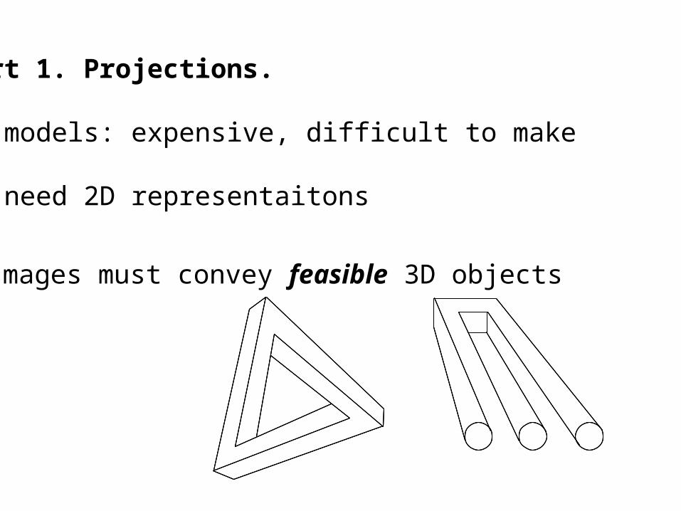
Part 1. Projections.
3D models: expensive, difficult to make
=> need 2D representaitons
Images must convey feasible 3D objects
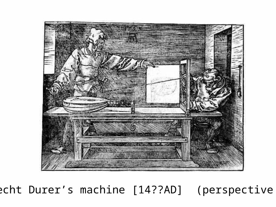
Albrecht Durer’s machine [14??AD] (perspective map)
1. Renaissance architects
2. Modern CAD systems
(a) 3D rendering, image processing
(b) Mathematics of free-form surfaces (NURBS)
Importance of perspective maps
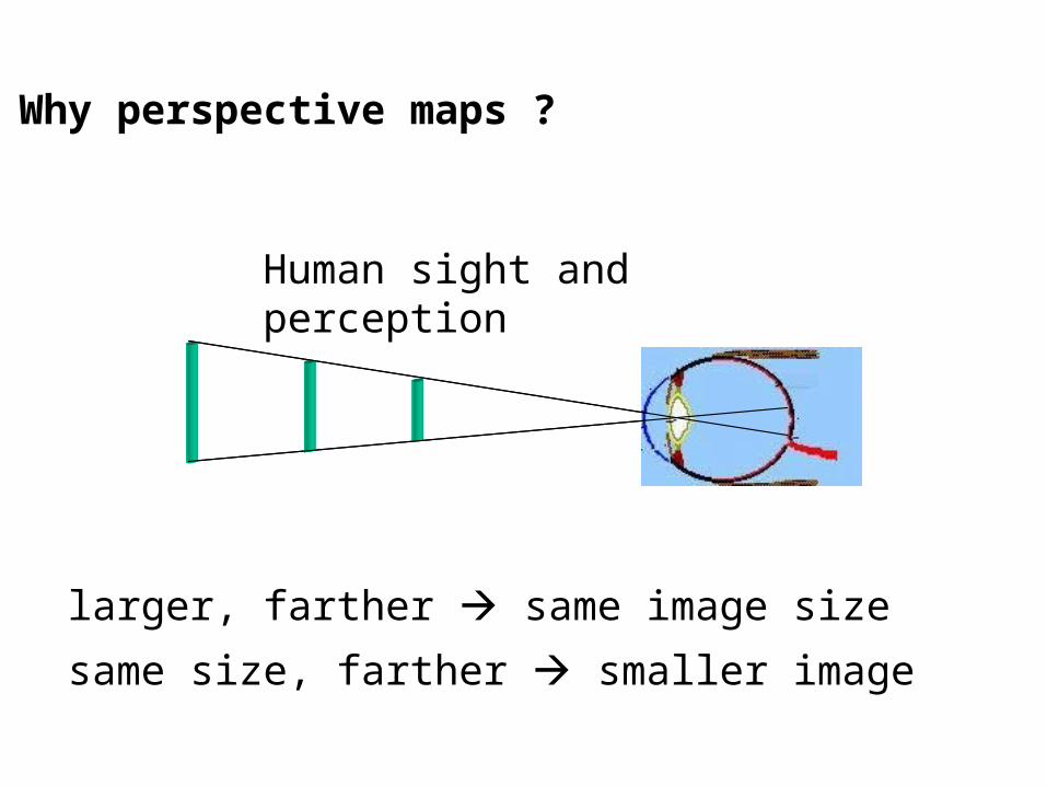
Why perspective maps ?
larger, farther same image size
same size, farther smaller image
Human sight and perception
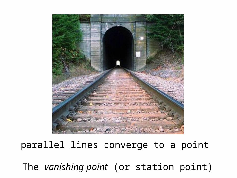
parallel lines converge to a point
The vanishing point (or station point)

Effect of vanishing point on perspective map
Image on the ‘picture plane’ is a perspective of the 3D object
[Is the object behind in perspective view ?]

para
llel
parallel
para
llel
converge:
finite vanishing point
converge:finite vanishing pointpa
ralle
l
parallel
para
llel
parallel
para
llel
converge:
finite vanishing point
converge:finite vanishing point
para
llel
converge:
finite vanishing point
converge:finite vanishing point
Perspectives and vanishing points
Perspectives in mechanical drafting Not good !
(1) parallel lines converge misinterpreted by the machinist
(2) Views have too many lines
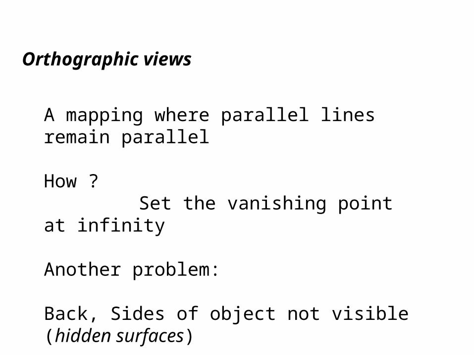
Orthographic views
A mapping where parallel lines remain parallel
How ?Set the vanishing point at infinity
Another problem:
Back, Sides of object not visible (hidden surfaces)
Solution: Multiple views
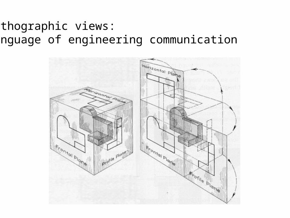
Orthographic views:Language of engineering communication
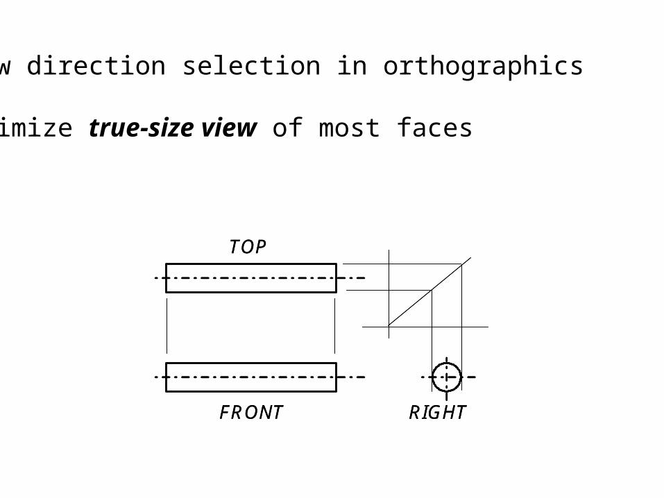
View direction selection in orthographics
Maximize true-size view of most faces
FRONT
TOP
RIGHTFRONT
TOP
RIGHT
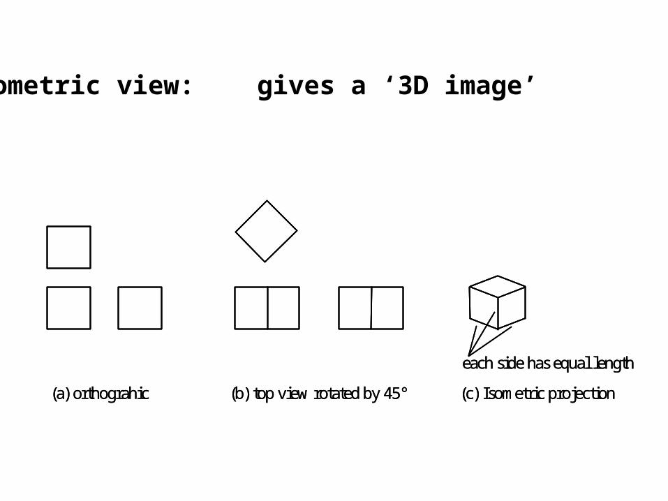
Isometric view: gives a ‘3D image’
each side has equal length
(a) orthograhic (b) top view rotated by 45° (c) Isometric projection
each side has equal length
(a) orthograhic (b) top view rotated by 45° (c) Isometric projection
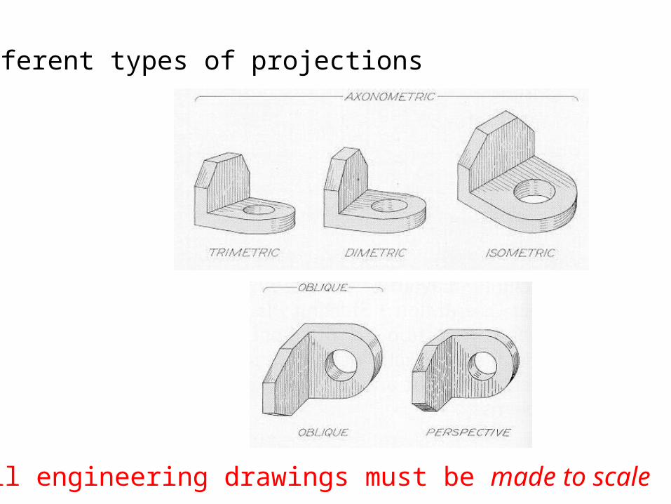
Different types of projections
All engineering drawings must be made to scale
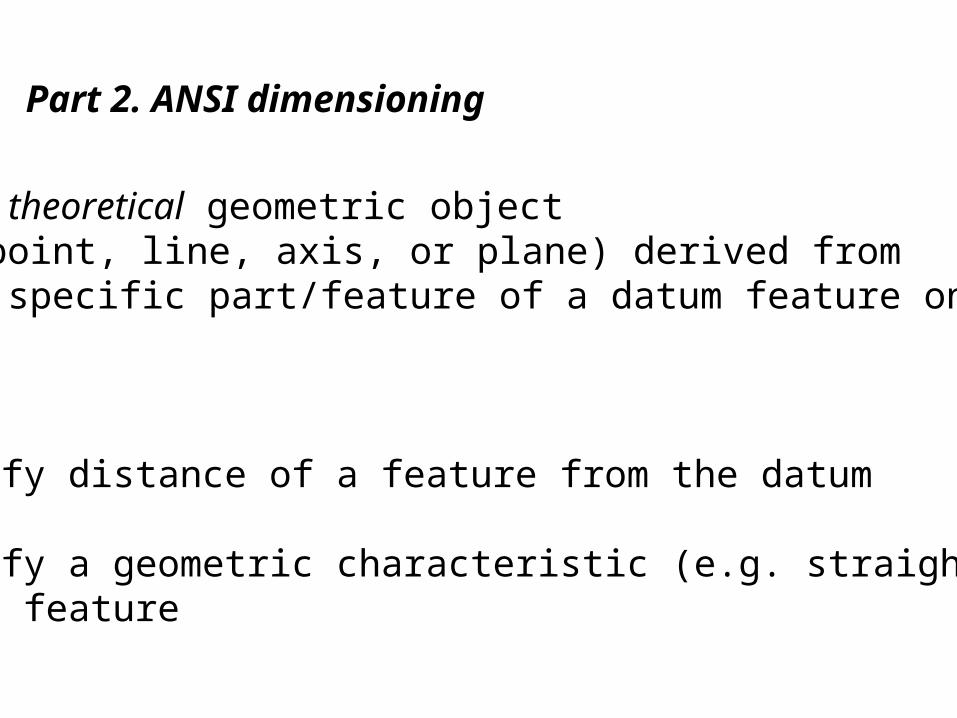
Datum: A theoretical geometric object (point, line, axis, or plane) derived from a specific part/feature of a datum feature on the part.
Uses:
(1) specify distance of a feature from the datum
(2) specify a geometric characteristic (e.g. straightness) of a feature
Part 2. ANSI dimensioning
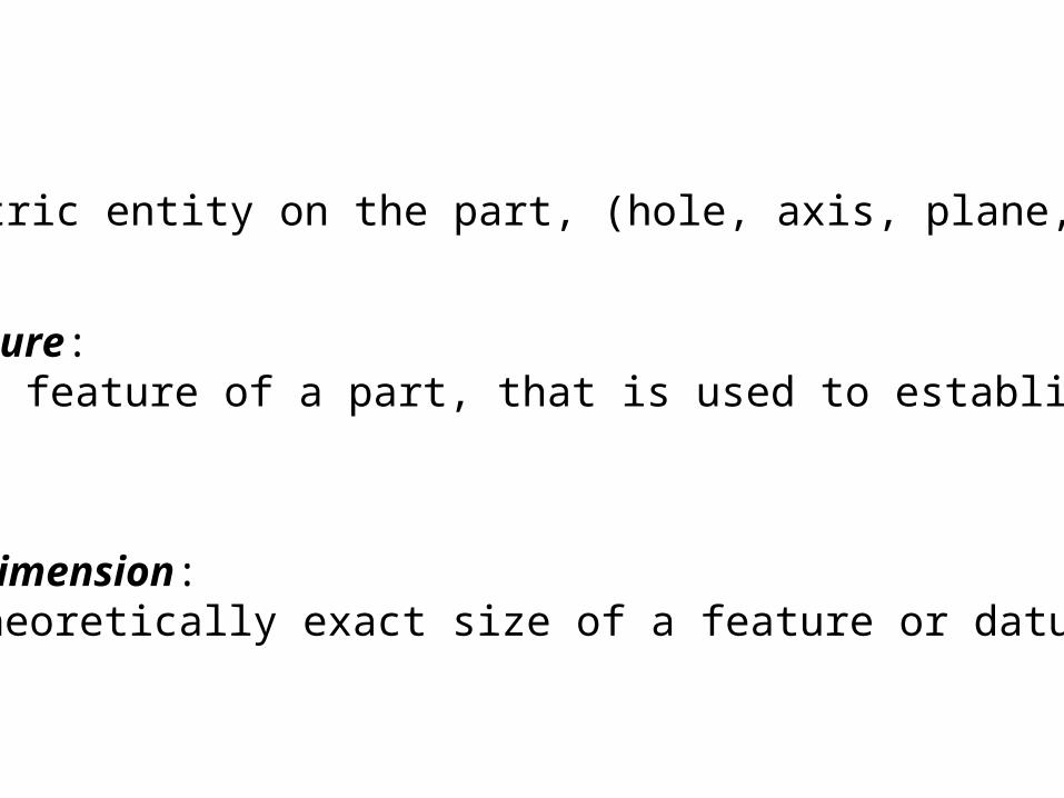
Basic Dimension:The theoretically exact size of a feature or datum
Feature:A geometric entity on the part, (hole, axis, plane, edge)
Datum feature:An actual feature of a part, that is used to establish a datum.
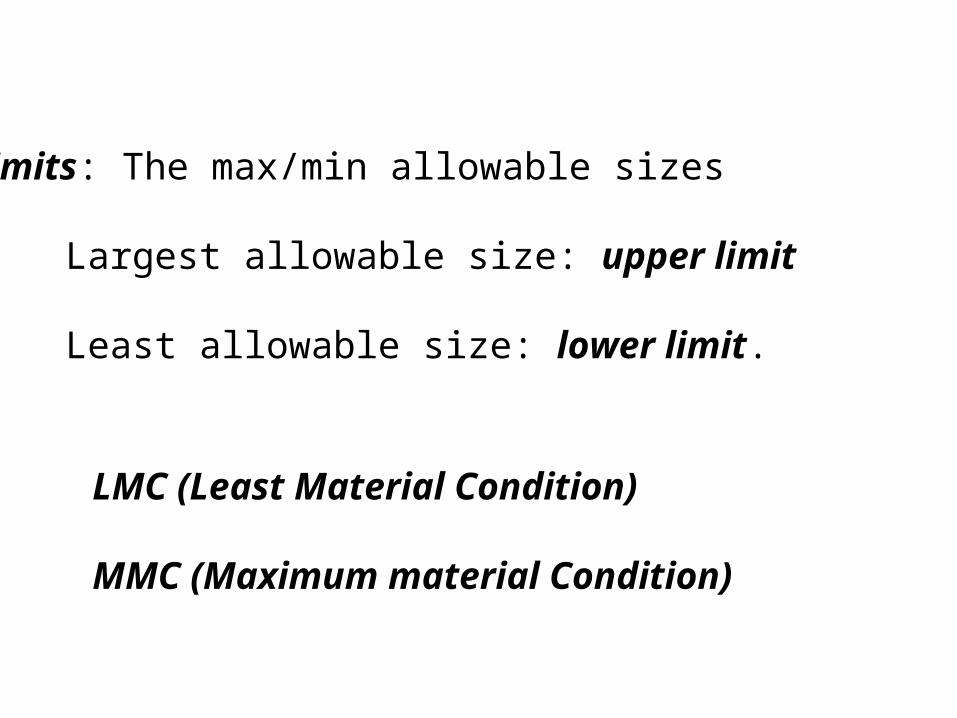
Limits: The max/min allowable sizes
Largest allowable size: upper limit
Least allowable size: lower limit.
LMC (Least Material Condition)
MMC (Maximum material Condition)
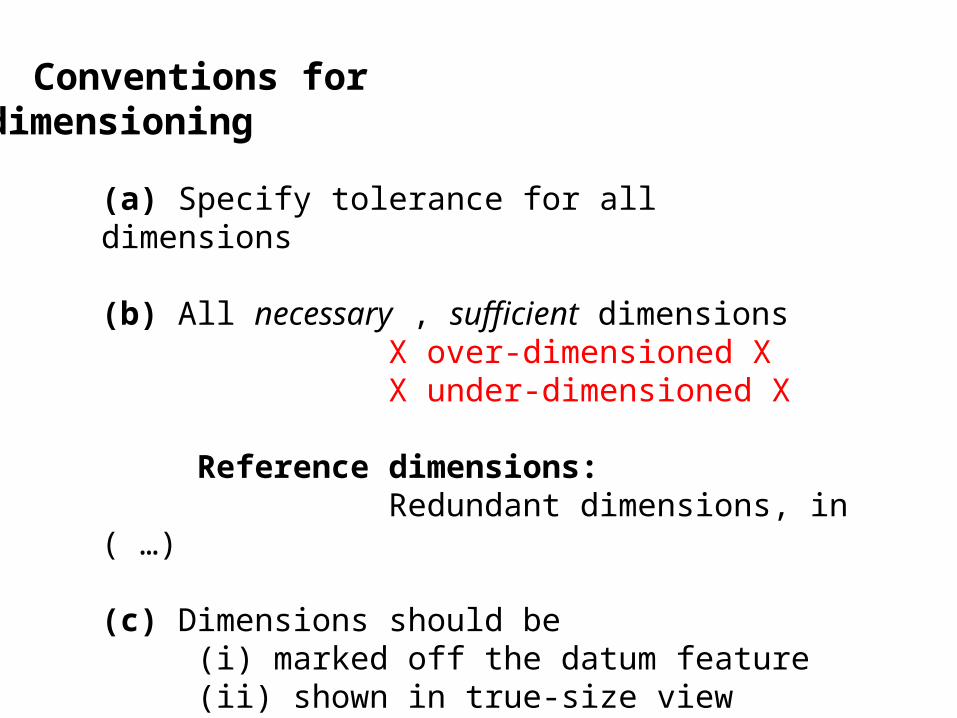
Conventions for dimensioning
(a) Specify tolerance for all dimensions
(b) All necessary , sufficient dimensionsX over-dimensioned XX under-dimensioned X
Reference dimensions:Redundant dimensions, in ( …)
(c) Dimensions should be (i) marked off the datum feature (ii) shown in true-size view (iii) shown in visible view
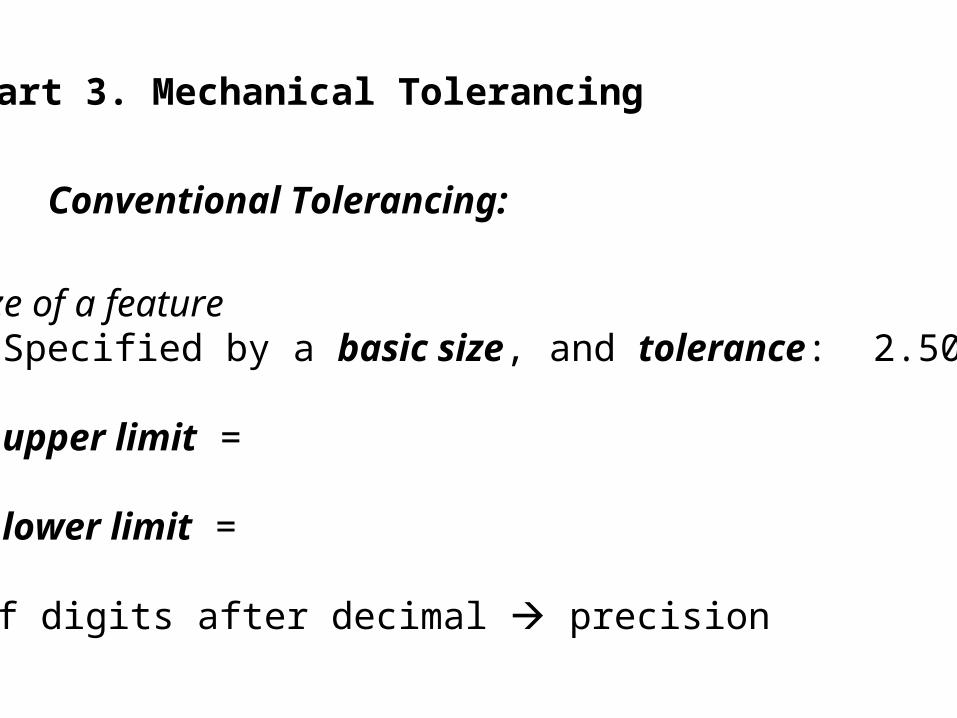
(a) Size of a featureSpecified by a basic size, and tolerance: 2.50±0.03
upper limit =
lower limit =
No of digits after decimal precision
Part 3. Mechanical Tolerancing
Conventional Tolerancing:

Unilateral and Bilateral Tolerances:
2.50+0.03- 0.03
+0.06+ 0.002.47
-0.00-0.062.532.49
+0.04- 0.02
bilateral unilateral-0.03-0.092.562.50
+0.03- 0.032.50+0.03- 0.03
+0.06+ 0.002.47+0.06+ 0.002.47
-0.00-0.062.53-0.00-0.062.532.49
+0.04- 0.022.49+0.04- 0.02
bilateral unilateral-0.03-0.092.56-0.03-0.092.56
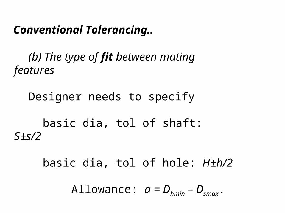
(b) The type of fit between mating features
Designer needs to specify
basic dia, tol of shaft: S±s/2
basic dia, tol of hole: H±h/2
Allowance: a = Dhmin – Dsmax.
Conventional Tolerancing..
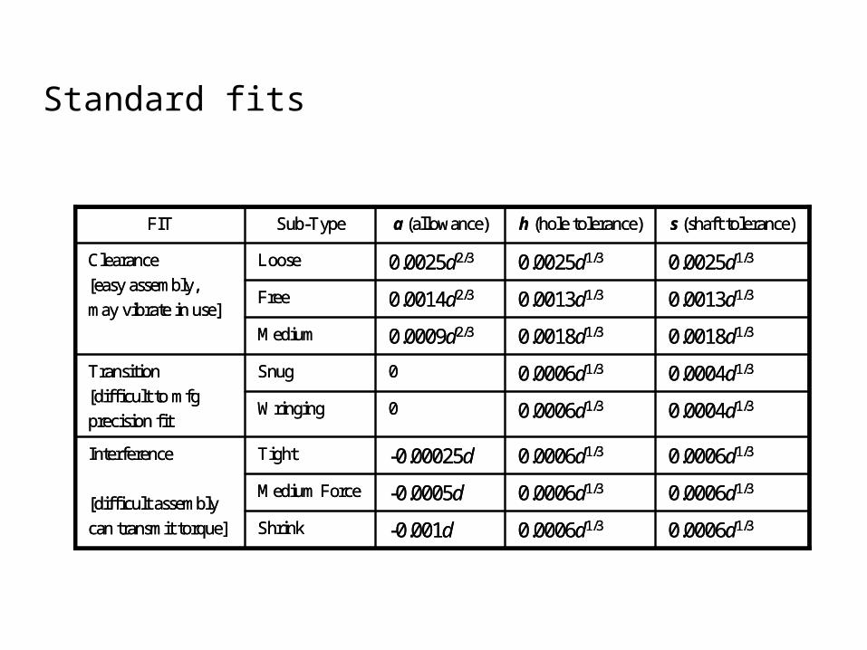
0.0006d1/30.0006d1/3-0.001dShrink
0.0006d1/30.0006d1/3-0.0005dMedium Force
0.0006d1/30.0006d1/3-0.00025dTightInterference
[difficult assembly
can transmit torque]
0.0004d1/30.0006d1/30Wringing
0.0004d1/30.0006d1/30SnugTransition
[difficult to mfg
precision fit
0.0018d1/30.0018d1/30.0009d2/3Medium
0.0013d1/30.0013d1/30.0014d2/3Free
0.0025d1/30.0025d1/30.0025d2/3LooseClearance
[easy assembly,
may vibrate in use]
s (shaft tolerance)h (hole tolerance)a (allowance)Sub-TypeFIT
Standard fits
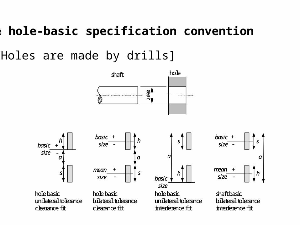
The hole-basic specification convention
shaft hole
2.00
0+-
h
a
s
basicsize
hole basicunilateral toleranceclearance fit
+-
h
a
s
basicsize
hole basicbilateral toleranceclearance fit
meansize
+- h
a
s
basicsize
hole basicunilateral toleranceinterference fit
+-
h
a
sbasic
size
shaft basicbilateral toleranceinterference fit
meansize
+-
shaft hole
2.00
0+-
h
a
s
basicsize
hole basicunilateral toleranceclearance fit
+-
h
a
s
basicsize
hole basicbilateral toleranceclearance fit
meansize
+- h
a
s
basicsize
hole basicunilateral toleranceinterference fit
+-
h
a
sbasic
size
shaft basicbilateral toleranceinterference fit
meansize
+-
[Holes are made by drills]
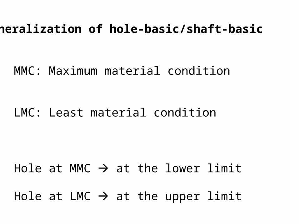
Generalization of hole-basic/shaft-basic
MMC: Maximum material condition
LMC: Least material condition
Hole at MMC at the lower limit
Hole at LMC at the upper limit
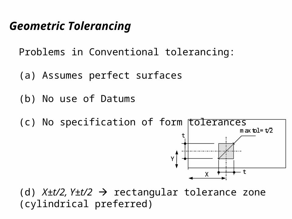
Geometric Tolerancing
Y
X
t
t
max tol = t 2
Y
X
t
t
max tol = t 2
Problems in Conventional tolerancing:
(a) Assumes perfect surfaces
(b) No use of Datums
(c) No specification of form tolerances
(d) X±t/2, Y±t/2 rectangular tolerance zone (cylindrical preferred)

Datums
A theoretical feature (e.g. plane, line)
Serves as a global coordinate frame for the part
during different activities such as
design, manufacturing and inspection.
Each design must specify the datum planes(or other datums)
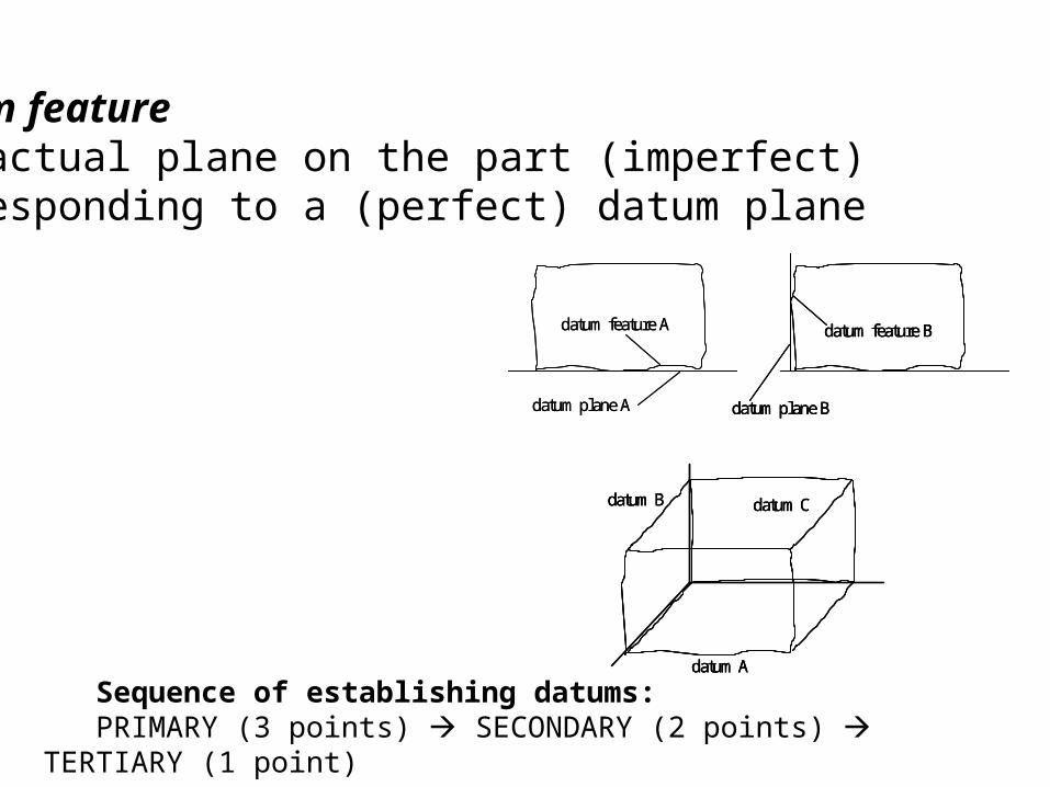
Datum feature The actual plane on the part (imperfect) corresponding to a (perfect) datum plane
datum feature A
datum plane A
datum feature B
datum plane B
datum A
datum B datum C
datum feature A
datum plane A
datum feature B
datum plane B
datum feature B
datum plane B
datum A
datum B datum C
datum A
datum B datum C
Sequence of establishing datums:PRIMARY (3 points) SECONDARY (2 points) TERTIARY (1 point)
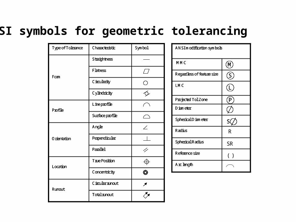
ANSI symbols for geometric tolerancing
True Position
Location
Total runout
Circular runout
Runout
Concentricity
Parallel
Perpendicular
Angle
Orientation
Surface profile
Line profile
Profile
Cylindricity
Circularity
Flatness
Straightness
Form
SymbolCharacteristicType of Tolerance
True Position
Location
Total runout
Circular runout
Runout
Concentricity
Parallel
Perpendicular
Angle
Orientation
Surface profile
Line profile
Profile
Cylindricity
Circularity
Flatness
Straightness
Form
SymbolCharacteristicType of Tolerance
MMC
Arc length
Reference size
Spherical Radius
Radius
Spherical Diameter
Diameter
Projected Tol Zone
LMC
Regardless of feature size
ANSI modification symbols
MMC
Arc length
Reference size
Spherical Radius
Radius
Spherical Diameter
Diameter
Projected Tol Zone
LMC
Regardless of feature size
ANSI modification symbols
MM
SS
LL
PP
SS
R
SR
( )
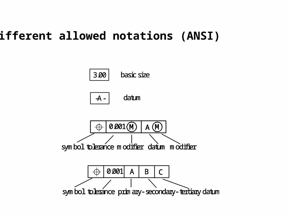
3.00
-A-
symbol tolerance modifier datum modifier
0.001 M MA
datum
basic size
symbol tolerance primary- secondary- tertiary datum
0.001 A B C
3.00
-A-
symbol tolerance modifier datum modifier
0.001 M MA
symbol tolerance modifier datum modifier
0.001 M MA0.001 MM MMA
datum
basic size
symbol tolerance primary- secondary- tertiary datum
0.001 A B C
symbol tolerance primary- secondary- tertiary datum
0.001 A B C
Different allowed notations (ANSI)
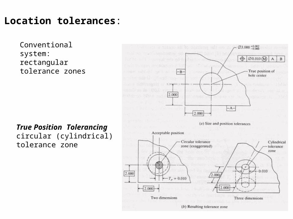
Location tolerances:
Conventional system:rectangular tolerance zones
True Position Tolerancingcircular (cylindrical) tolerance zone
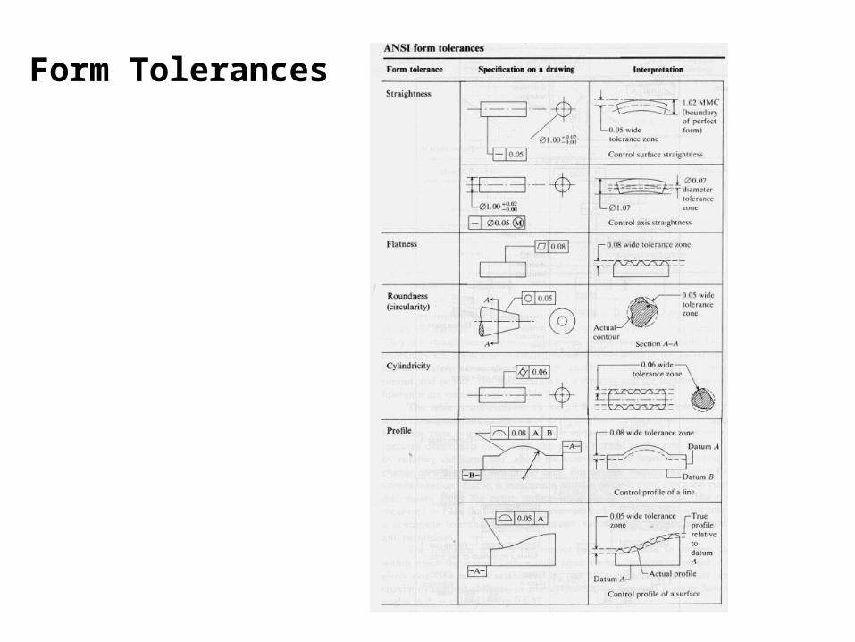
Form Tolerances

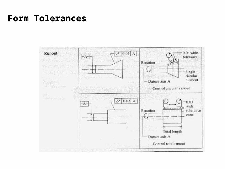
Form Tolerances
Form Tolerances


