63
Dimensioning (WEEK 2) 1
| Date post: | 28-Dec-2015 |
| Category: |
Documents |
| Upload: | ronald-gordon |
| View: | 264 times |
| Download: | 3 times |

1
Dimensioning(WEEK 2)
2
LECTURE OBJECTIVES
Introduction
Dimensioning components
Dimensioning object’ s features
Placement of dimensions.
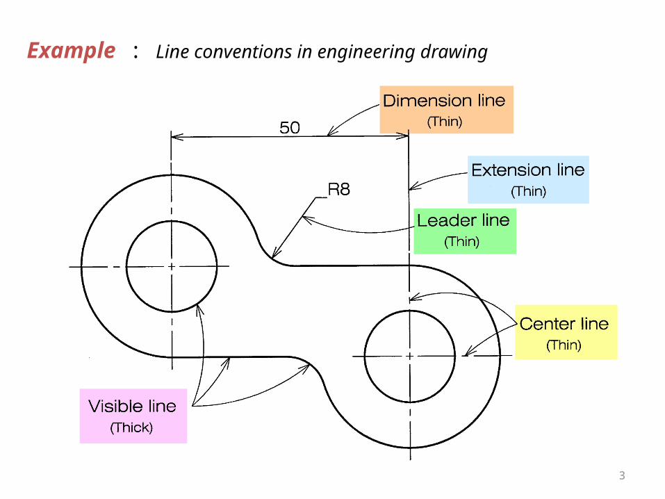
Example : Line conventions in engineering drawing
3
4
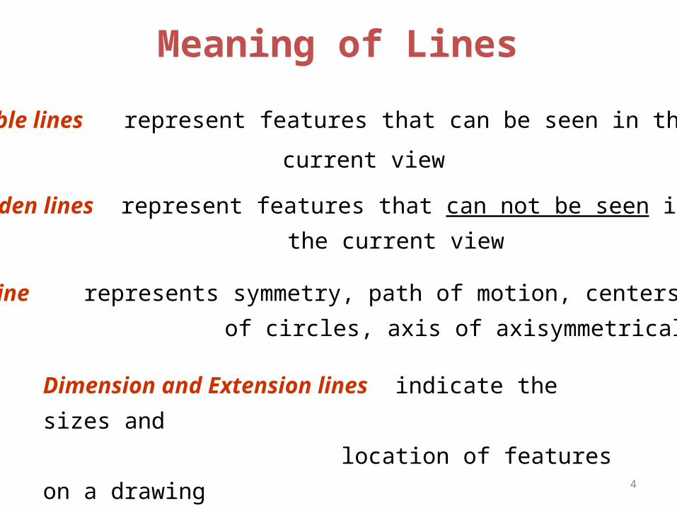
Visible lines represent features that can be seen in the
current view
Meaning of Lines
Hidden lines represent features that can not be seen in
the current view
Center line represents symmetry, path of motion, centers
of circles, axis of axisymmetrical parts
Dimension and Extension lines indicate the sizes and
location of features on a drawing
5
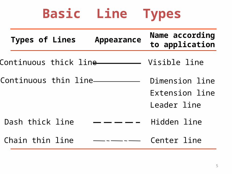
Basic Line Types
Types of Lines AppearanceName according
to application
Continuous thick line Visible line
Continuous thin line Dimension line
Extension line
Leader line
Dash thick line Hidden line
Chain thin line Center line

6
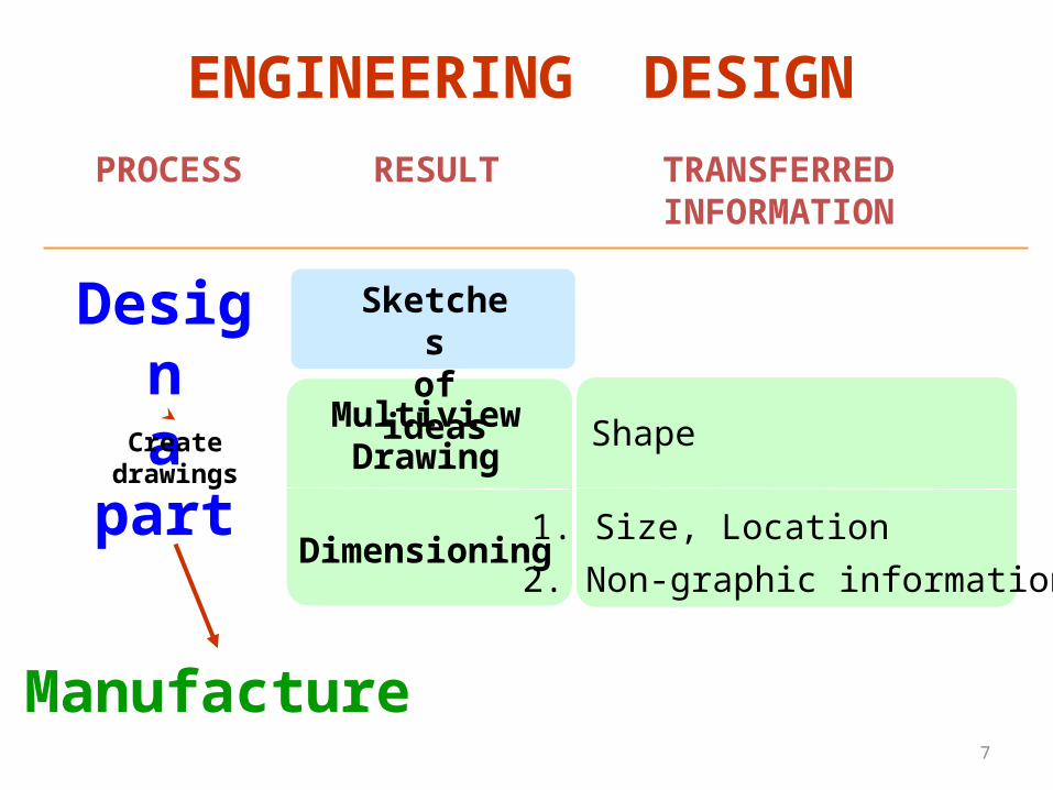
Introduction
7
ShapeMultiviewDrawing
Dimensioning
Designa part
1. Size, Location
ENGINEERING DESIGN
2. Non-graphic information
TRANSFERREDINFORMATION
Createdrawings
Manufacture
RESULT
Sketchesof ideas
PROCESS
8
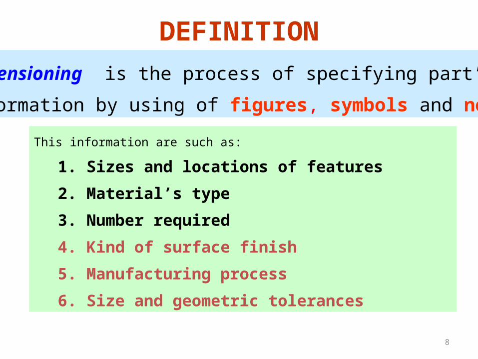
DEFINITION
Dimensioning is the process of specifying part’ s
information by using of figures, symbols and notes.
This information are such as:
1. Sizes and locations of features
2. Material’s type
3. Number required
4. Kind of surface finish
5. Manufacturing process
6. Size and geometric tolerances
9
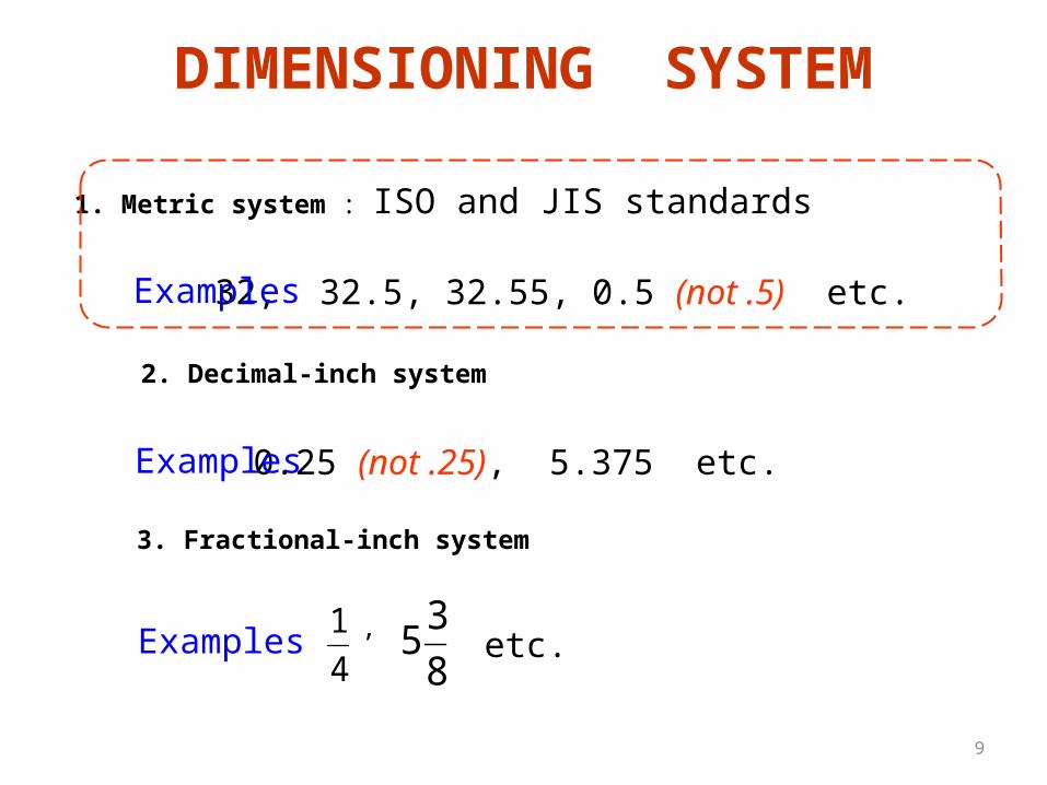
DIMENSIONING SYSTEM
4
1
1. Metric system : ISO and JIS standards
2. Decimal-inch system
3. Fractional-inch system
8
35,
0.25 (not .25), 5.375 etc.Examples
Examples
32, 32.5, 32.55, 0.5 (not .5) etc. Examples
etc.
10
DimensioningComponents
11
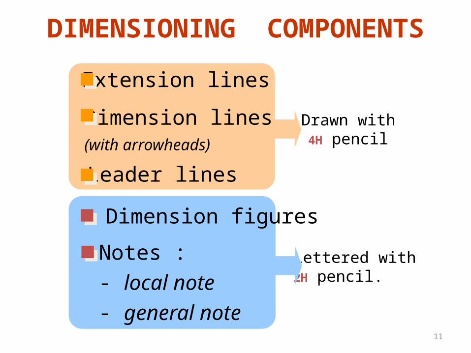
DIMENSIONING COMPONENTS
Extension lines
Dimension lines(with arrowheads)
Leader lines
Dimension figures
Notes :
- local note
- general note
Drawn with4H pencil
Lettered with2H pencil.
12
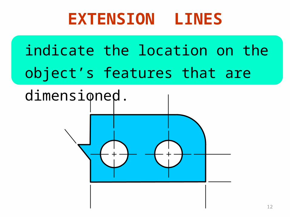
indicate the location on the object’s
features that are dimensioned.
EXTENSION LINES
13
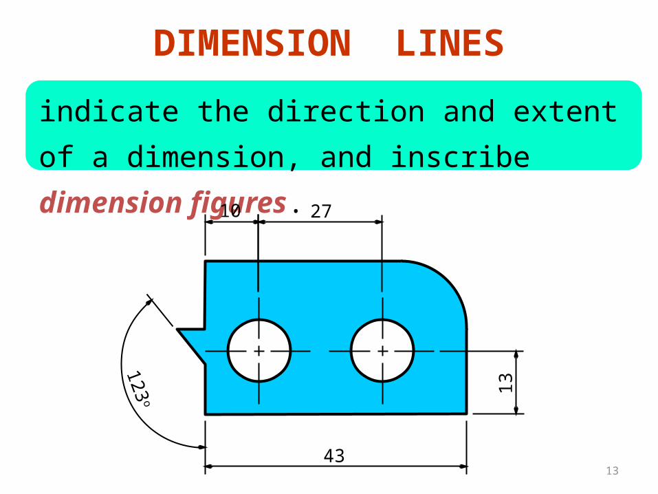
DIMENSION LINES
indicate the direction and extent of a
dimension, and inscribe dimension figures.
10 27
43
13123
o
14
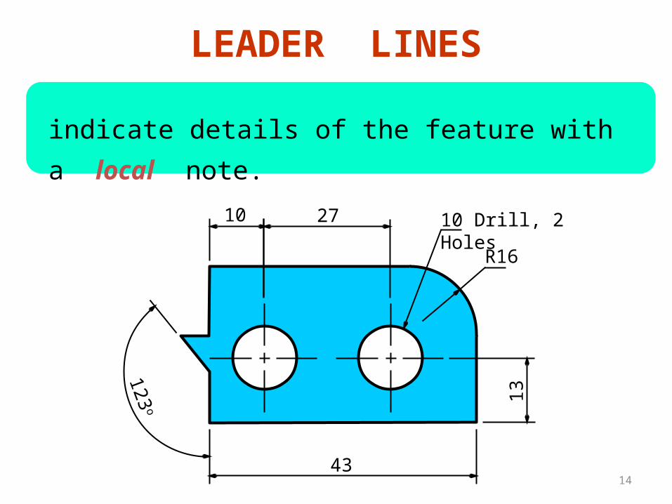
indicate details of the feature with a local note.
LEADER LINES
10 27
43
13123
o
10 Drill, 2 Holes
R16

15
RecommendedPractices
16
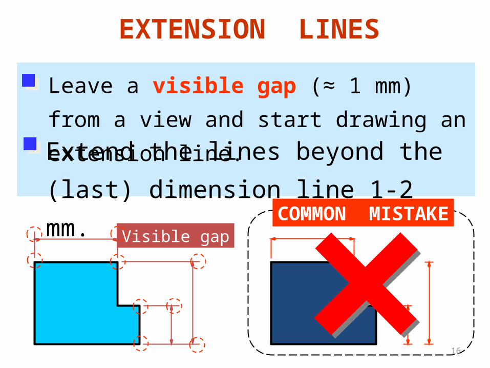
EXTENSION LINES
Leave a visible gap (≈ 1 mm) from a view
and start drawing an extension line.
Extend the lines beyond the (last)
dimension line 1-2 mm.
Visible gapCOMMON MISTAKE
17
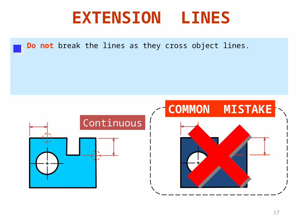
Do not break the lines as they cross object lines.
COMMON MISTAKEContinuous
EXTENSION LINES
18
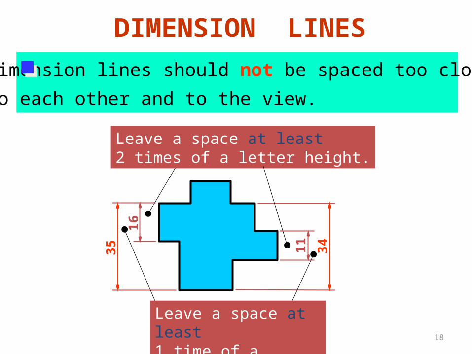
Dimension lines should not be spaced too close
to each other and to the view.
11 34
Leave a space at least2 times of a letter height.
16
35
DIMENSION LINES
Leave a space at least1 time of a letter height.
19
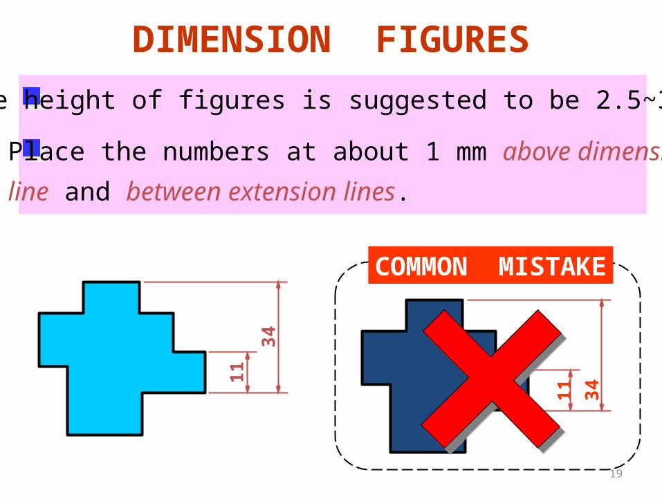
DIMENSION FIGURES
The height of figures is suggested to be 2.5~3 mm.
Place the numbers at about 1 mm above dimension
line and between extension lines.
COMMON MISTAKE
11
11
34
34
20
16.2516.25
or
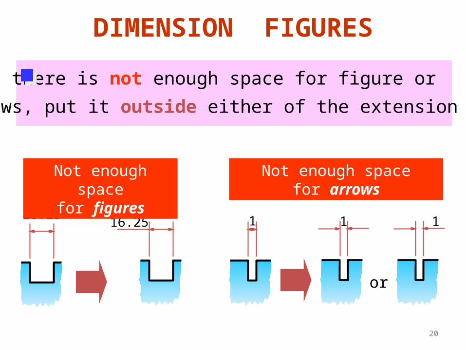
DIMENSION FIGURES
When there is not enough space for figure or
arrows, put it outside either of the extension lines.
1
Not enough spacefor figures
Not enough spacefor arrows
1 1
21
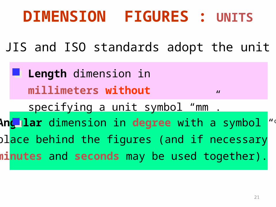
The JIS and ISO standards adopt the unit of
Angular dimension in degree with a symbol “o”
place behind the figures (and if necessary
minutes and seconds may be used together).
DIMENSION FIGURES : UNITS
Length dimension in millimeters without
specifying a unit symbol “mm”.
22
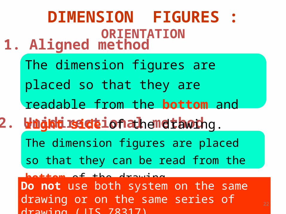
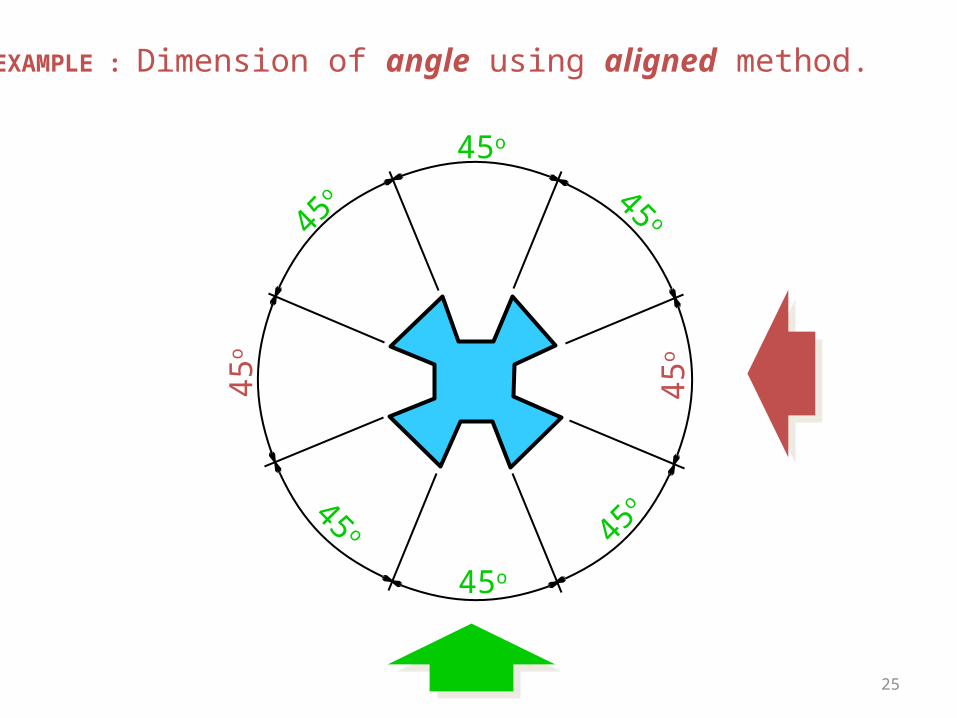
1. Aligned method
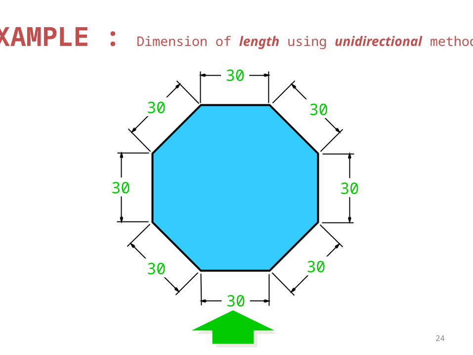
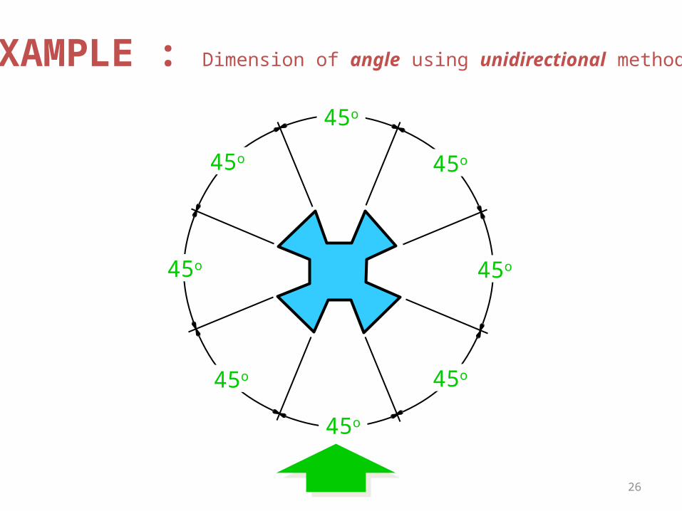
2. Unidirectional method
The dimension figures are placed so that
they are readable from the bottom and
right side of the drawing.
The dimension figures are placed so that they
can be read from the bottom of the drawing.
Do not use both system on the same drawing or on the same series of drawing (JIS Z8317)
DIMENSION FIGURES : ORIENTATION
2330
30
30
30
30
3030
30
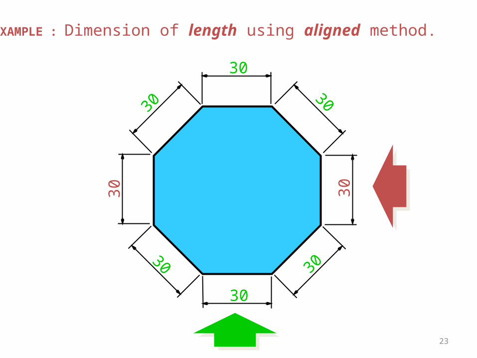
EXAMPLE : Dimension of length using aligned method.
24
30
30
30
30
3030
30
30
EXAMPLE : Dimension of length using unidirectional method.
25
45 o
45 o
45o
45o
45o
45o
45o
45o
EXAMPLE : Dimension of angle using aligned method.
26
45o
45o
45o
45o
45o45o
45o
45o
EXAMPLE : Dimension of angle using unidirectional method.
27
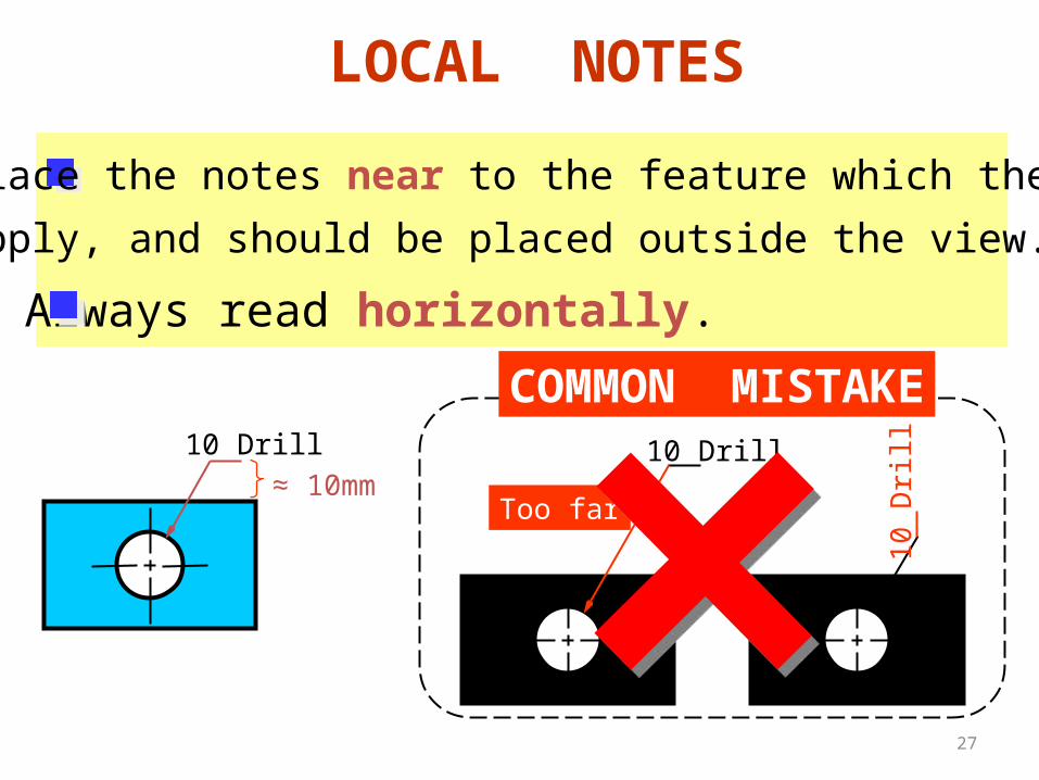
LOCAL NOTES
Place the notes near to the feature which they
apply, and should be placed outside the view.
Always read horizontally.
10 Drill
COMMON MISTAKE10 Drill
≈ 10mm
10
Dri
ll
Too far

28
DimensioningPractices
29
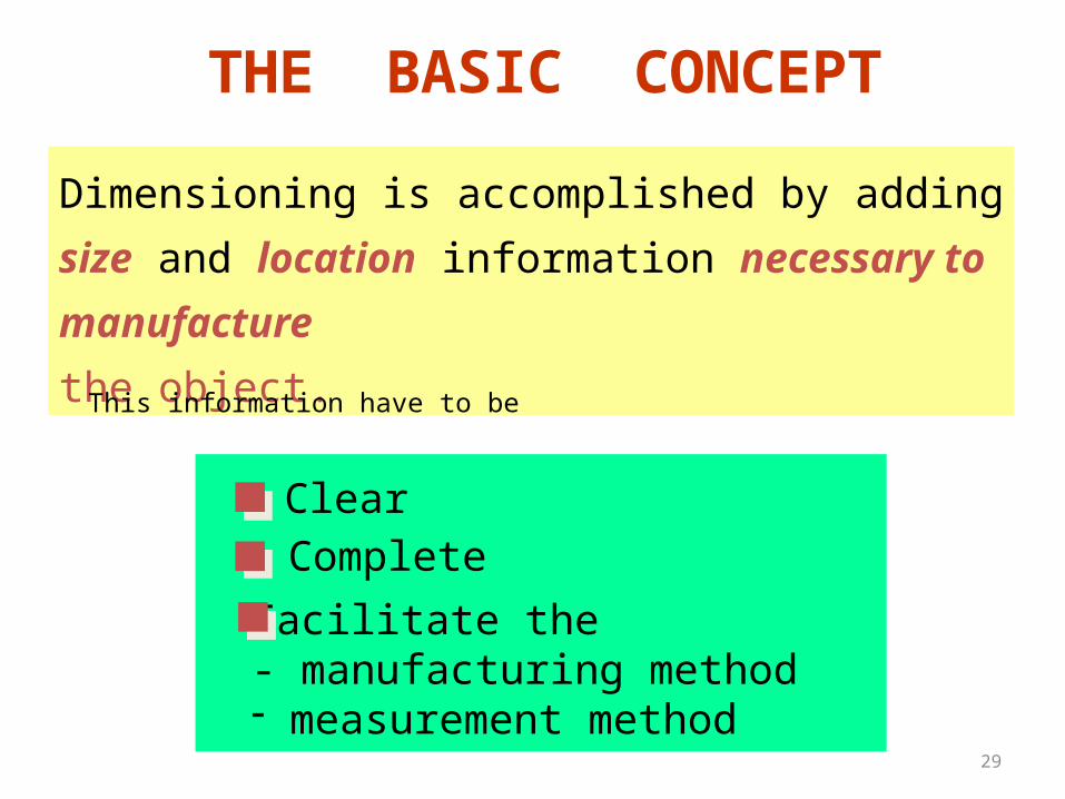
THE BASIC CONCEPT
Dimensioning is accomplished by adding size and
location information necessary to manufacture
the object.
ClearComplete
Facilitate the- manufacturing method- measurement method
This information have to be
30
L
L
S
S
S
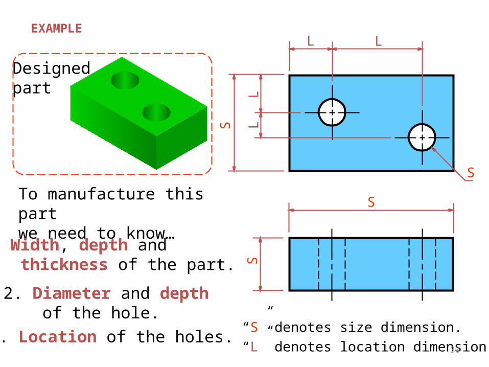
Designedpart
EXAMPLE
To manufacture this part we need to know…
1. Width, depth and thickness of the part.
2. Diameter and depth of the hole.
3. Location of the holes.“S” denotes size dimension.
“L” denotes location dimension.
S
L
L
31
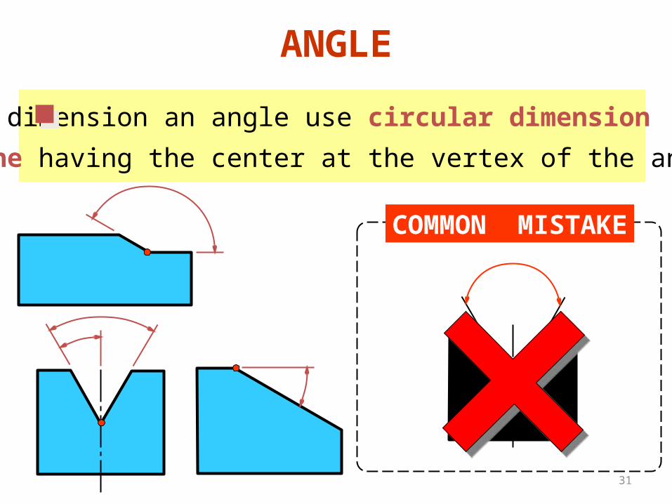
ANGLE
To dimension an angle use circular dimension
line having the center at the vertex of the angle.
COMMON MISTAKE
32
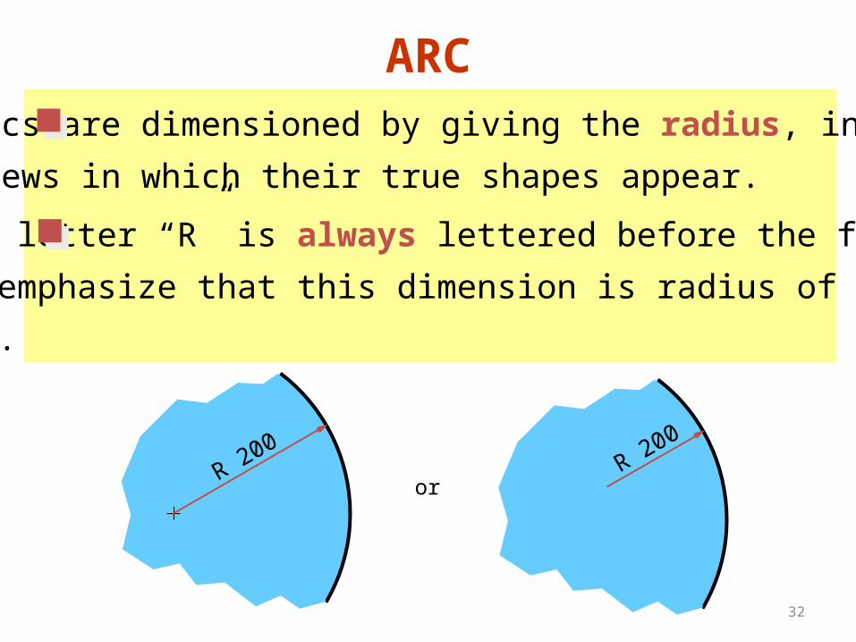
ARCArcs are dimensioned by giving the radius, in the
views in which their true shapes appear.
R 200
The letter “R” is always lettered before the figures
to emphasize that this dimension is radius of an
arc.
R 200
or
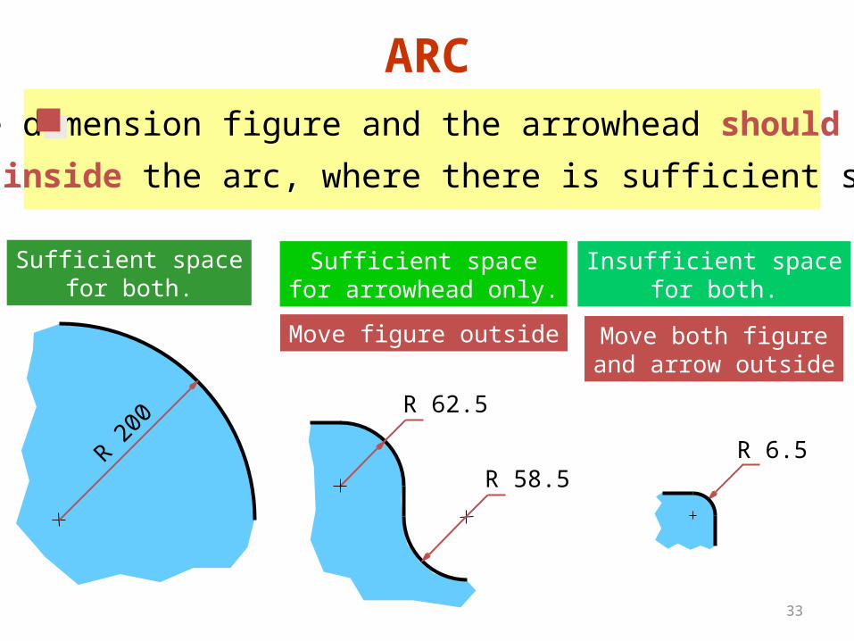
33
ARCThe dimension figure and the arrowhead should
be inside the arc, where there is sufficient space.
R 200
R 62.5
Move figure outside
R 6.5
Move both figureand arrow outside
Sufficient spacefor both.
Sufficient spacefor arrowhead only.
R 58.5
Insufficient spacefor both.
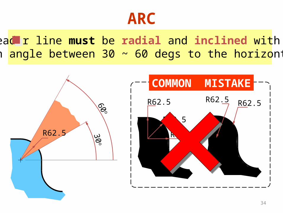
34
ARCLeader line must be radial and inclined withan angle between 30 ~ 60 degs to the horizontal.
COMMON MISTAKE
R62.5
R62.5
R62.5
R62.5R62.5
30o
60o
R62.5
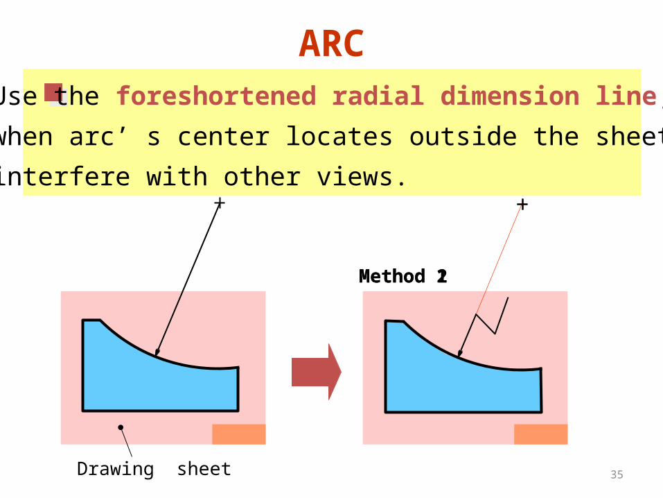
35
ARCUse the foreshortened radial dimension line,
when arc’ s center locates outside the sheet or
interfere with other views.
Drawing sheet
Method 1Method 2
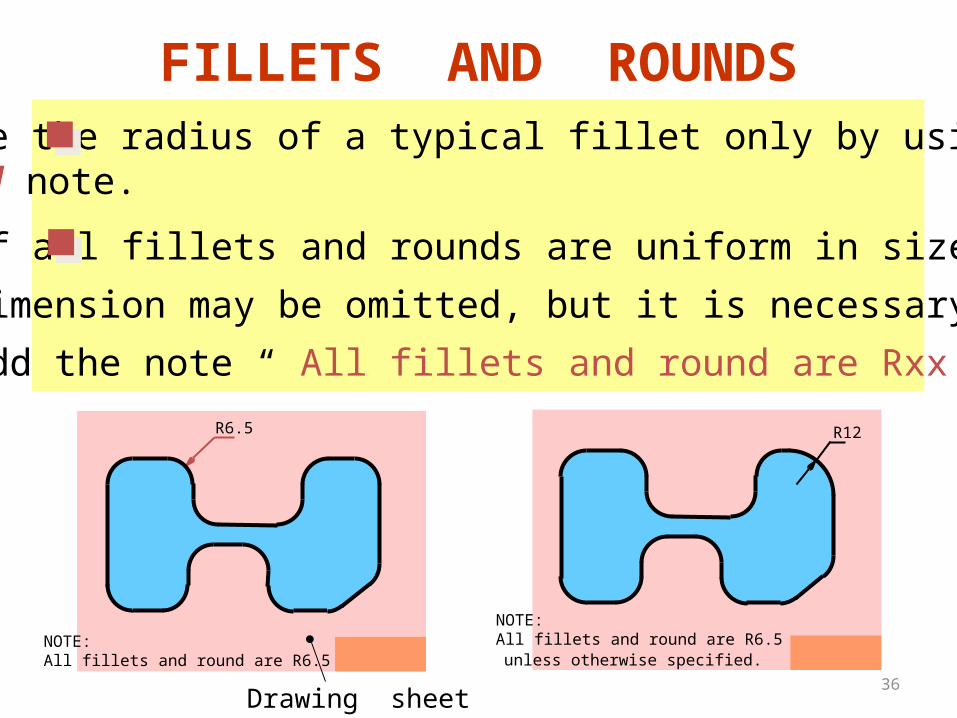
36
FILLETS AND ROUNDSGive the radius of a typical fillet only by using alocal note.
R6.5
If all fillets and rounds are uniform in size,
dimension may be omitted, but it is necessary to
add the note “ All fillets and round are Rxx. ”
NOTE:All fillets and round are R6.5
Drawing sheet
R12
unless otherwise specified.NOTE:All fillets and round are R6.5
37
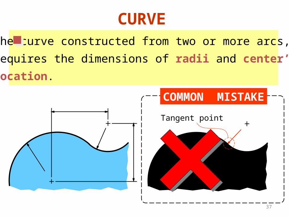
The curve constructed from two or more arcs,
requires the dimensions of radii and center’s
location.
CURVE
COMMON MISTAKE
Tangent point
38
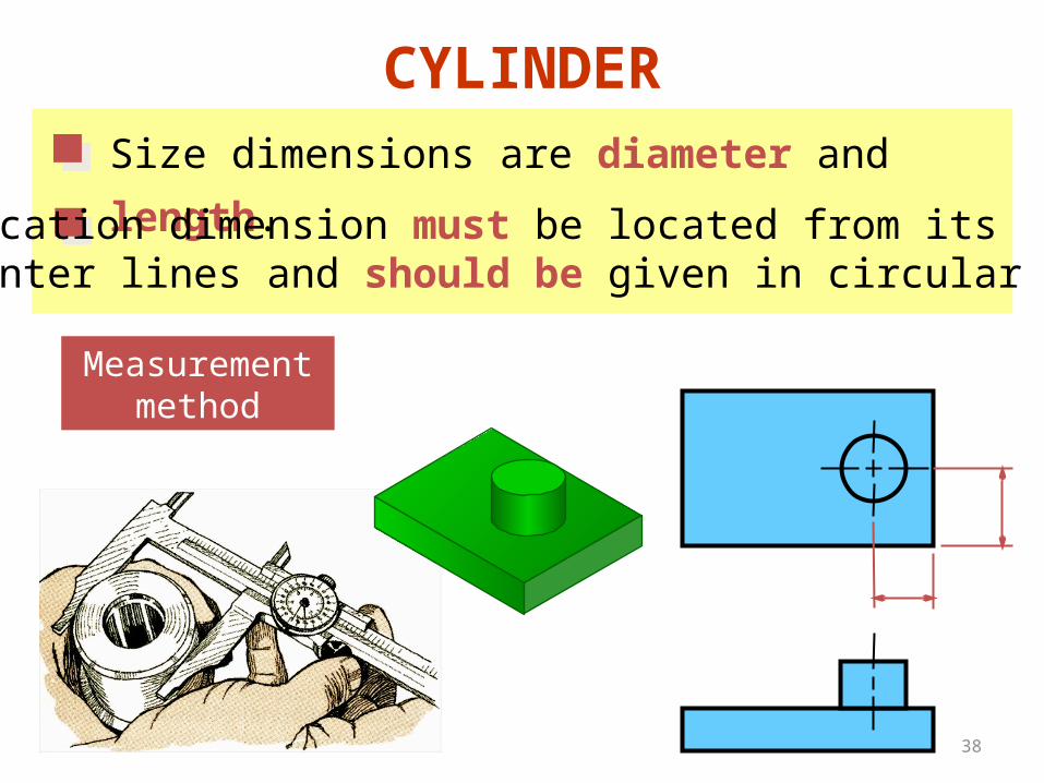
CYLINDERSize dimensions are diameter and length.
Measurementmethod
Location dimension must be located from itscenter lines and should be given in circular view.
39
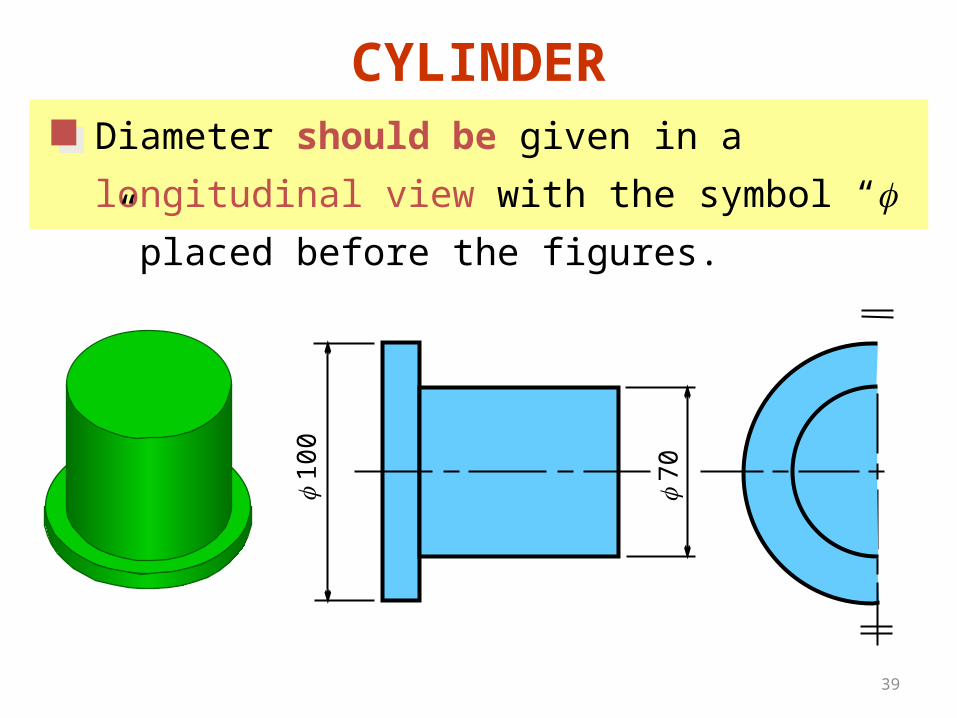
100
70
CYLINDERDiameter should be given in a longitudinal view
with the symbol “ ” placed before the figures.
40
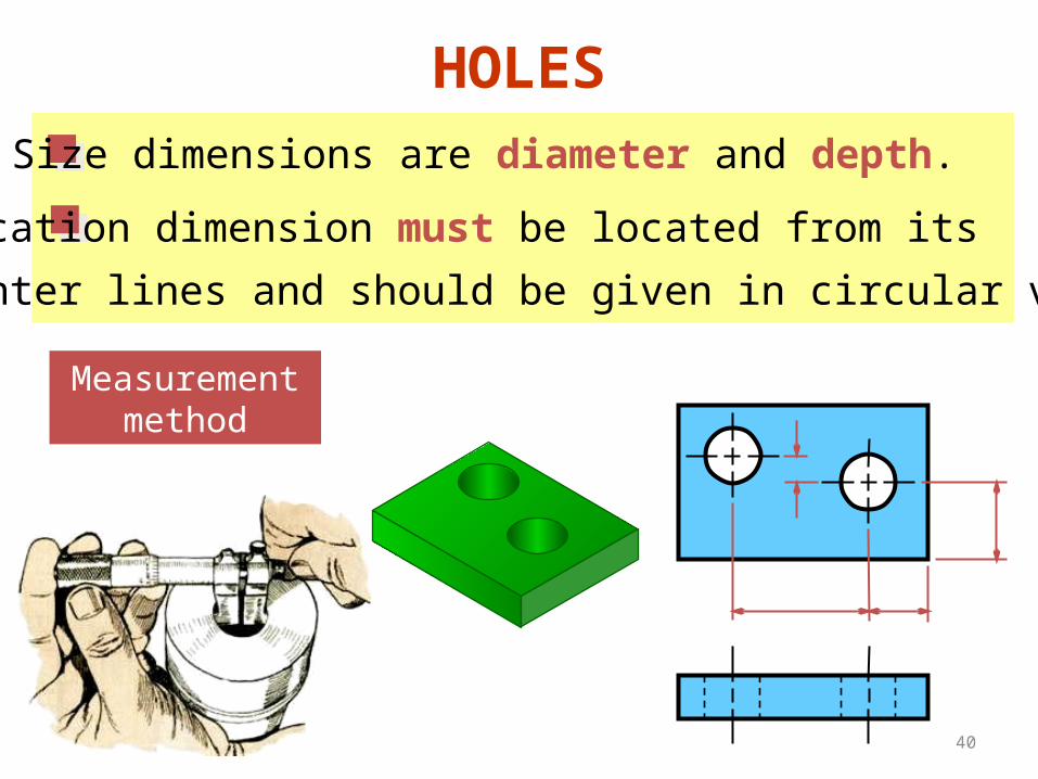
HOLESSize dimensions are diameter and depth.
Location dimension must be located from its
center lines and should be given in circular view.
Measurementmethod
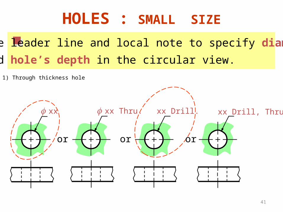
41
f xx
Use leader line and local note to specify diameter
and hole’s depth in the circular view.
HOLES : SMALL SIZE
xx Drill, Thru.
1) Through thickness hole
f xx Thru.
or
xx Drill.
or or
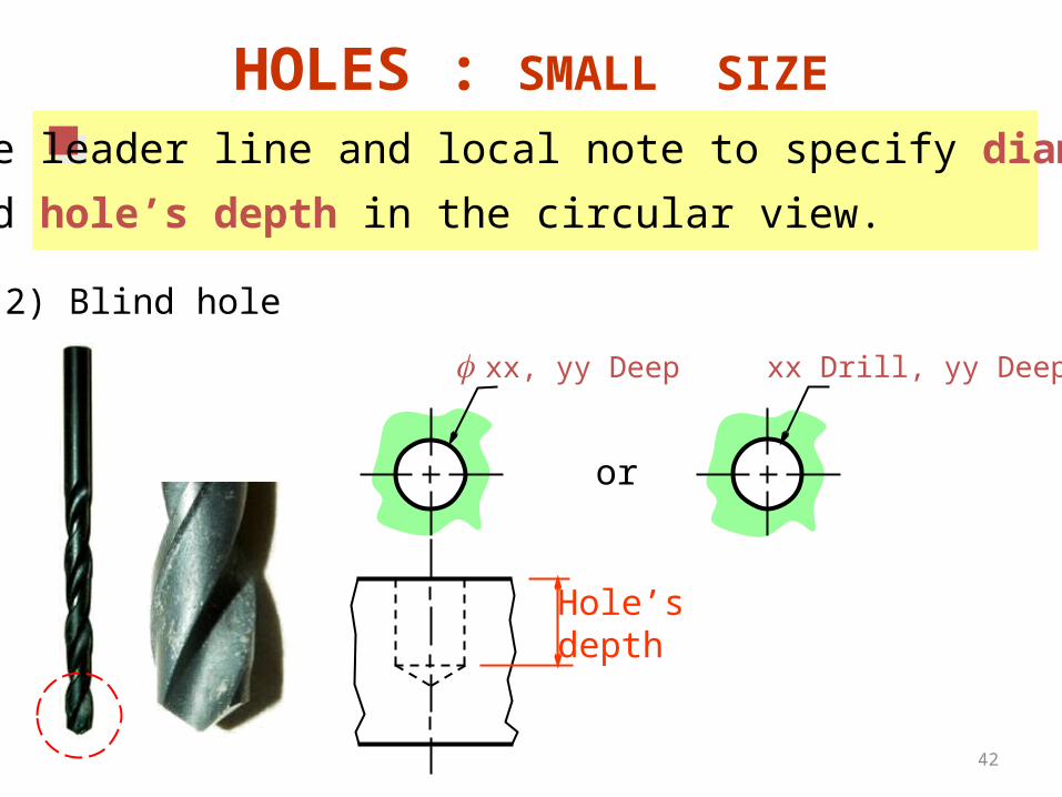
42
f xx, yy Deep
HOLES : SMALL SIZE
or
xx Drill, yy Deep
Hole’sdepth
Use leader line and local note to specify diameter
and hole’s depth in the circular view.
2) Blind hole
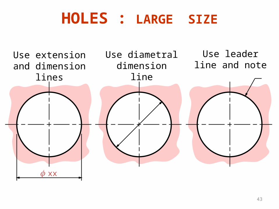
43
f xx
Use extension and dimension lines
Use diametral dimension line
Use leader line and note
HOLES : LARGE SIZE
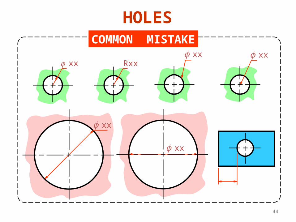
44
COMMON MISTAKE
f xxf xx f xx
Rxx
f xx
HOLES
f xx
45
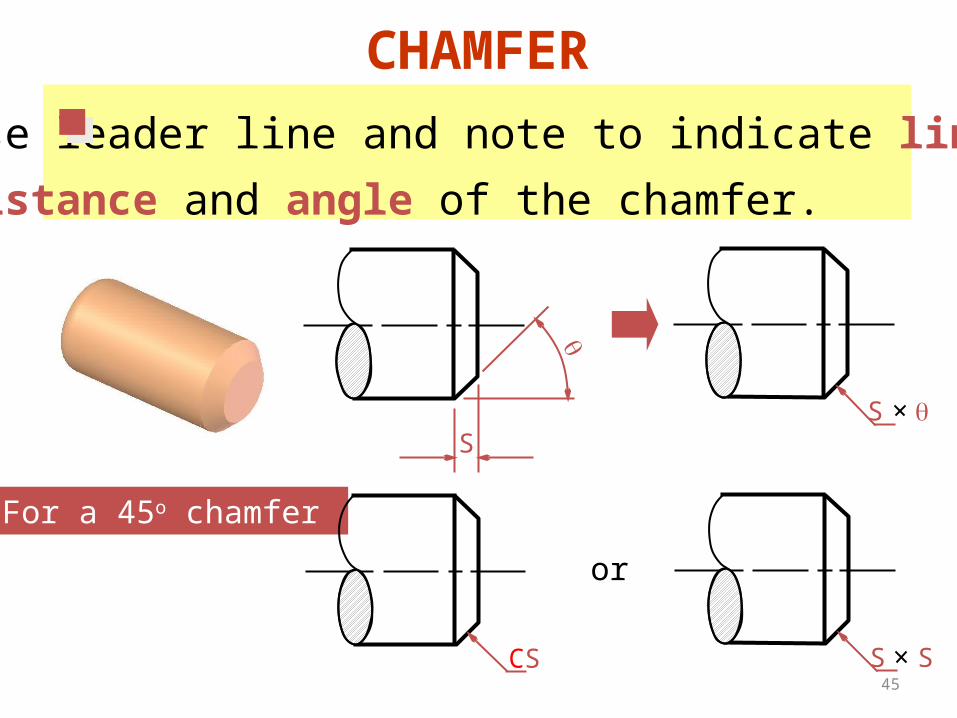
CHAMFER
Use leader line and note to indicate linear
distance and angle of the chamfer.
S
qS q
For a 45o chamfer
S SCS
or
46
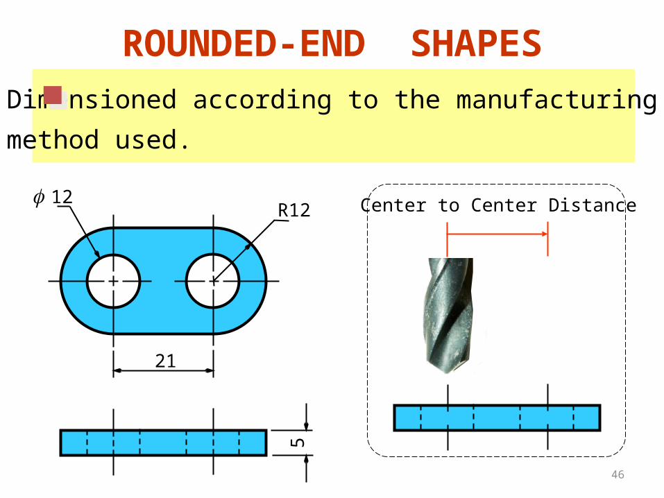
ROUNDED-END SHAPES
R12f 12
21
5
Dimensioned according to the manufacturing
method used.
Center to Center Distance
47
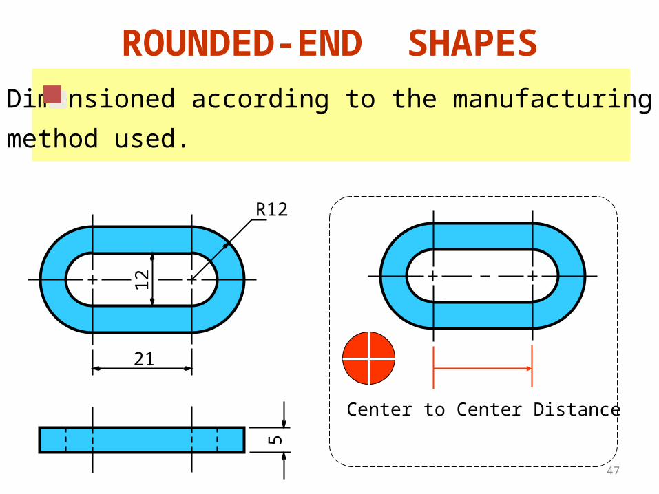
ROUNDED-END SHAPES
R12
21
5
12
Dimensioned according to the manufacturing
method used.
Center to Center Distance
48
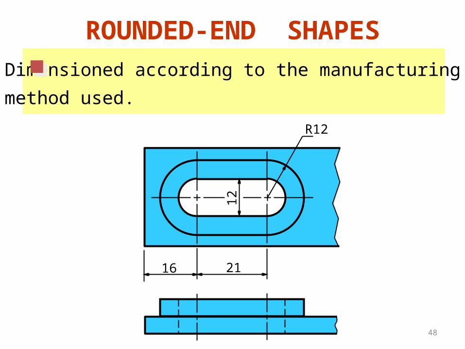
ROUNDED-END SHAPES
Dimensioned according to the manufacturing
method used.
R12
21
12
16
49
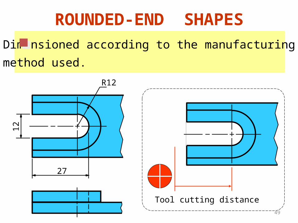
ROUNDED-END SHAPES
R12
27
12
Dimensioned according to the manufacturing
method used.
Tool cutting distance
50
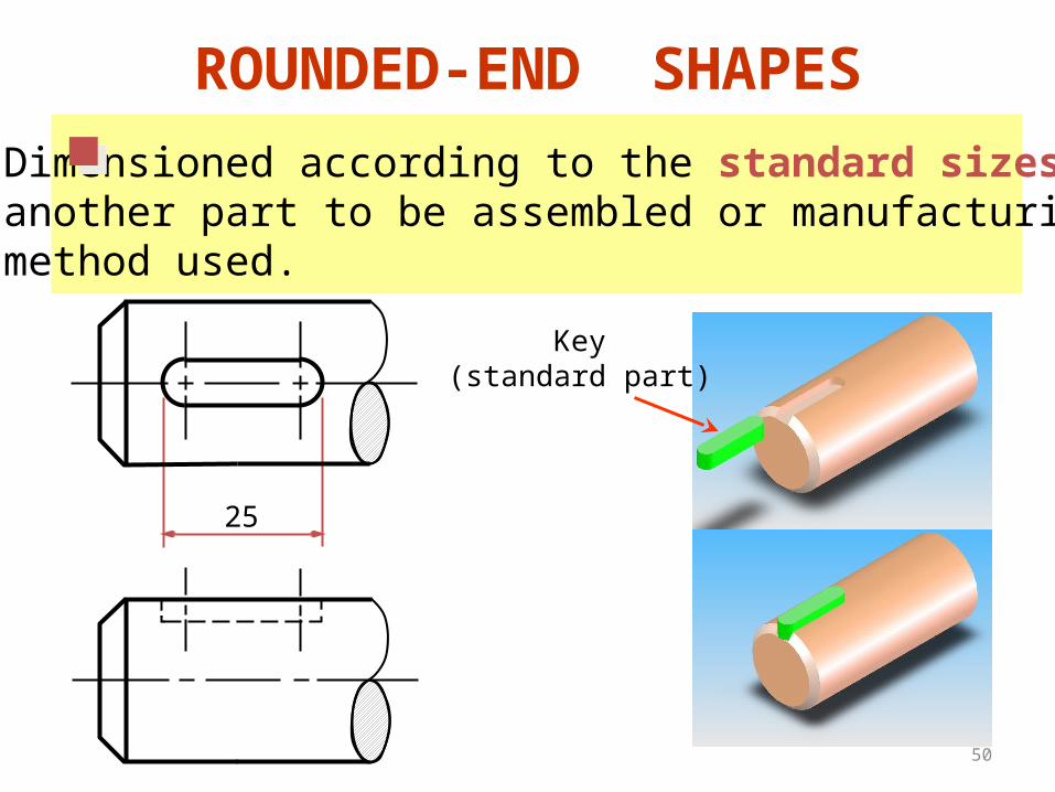
ROUNDED-END SHAPES
Dimensioned according to the standard sizes ofanother part to be assembled or manufacturing method used.
25
Key(standard part)
51
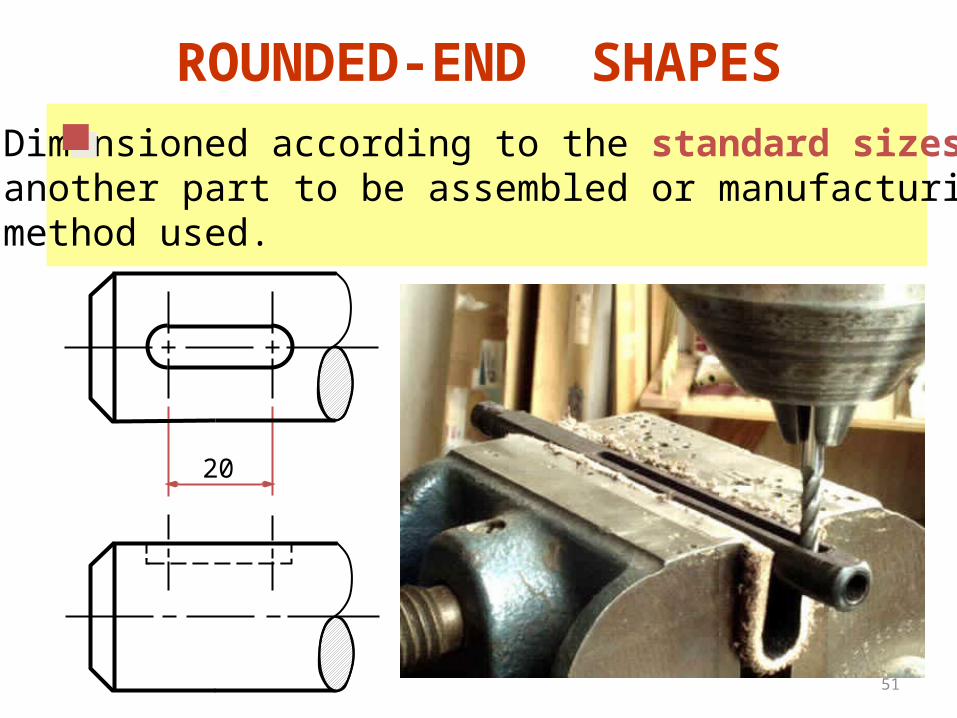
ROUNDED-END SHAPES
Dimensioned according to the standard sizes ofanother part to be assembled or manufacturing method used.
20

52

53
Placement ofDimensions
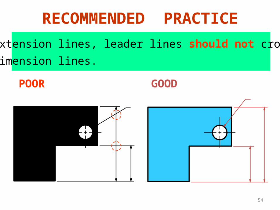
54
1. Extension lines, leader lines should not cross
dimension lines.
POOR GOOD
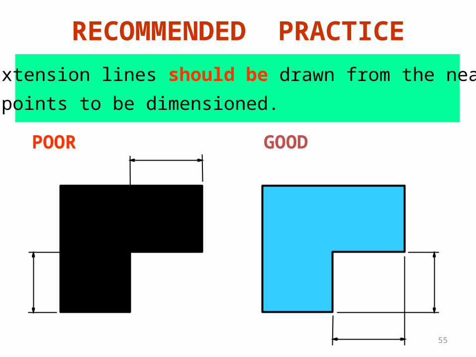
RECOMMENDED PRACTICE
55
2. Extension lines should be drawn from the nearest
points to be dimensioned.
POOR GOOD
RECOMMENDED PRACTICE
56
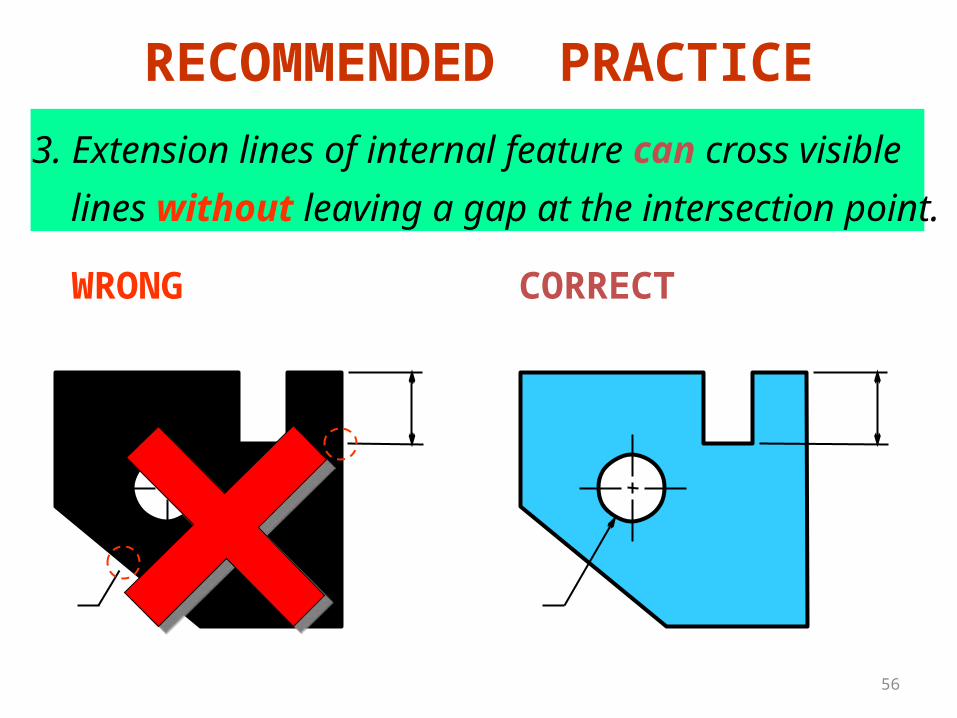
3. Extension lines of internal feature can cross visible
lines without leaving a gap at the intersection point.
WRONG CORRECT
RECOMMENDED PRACTICE
57
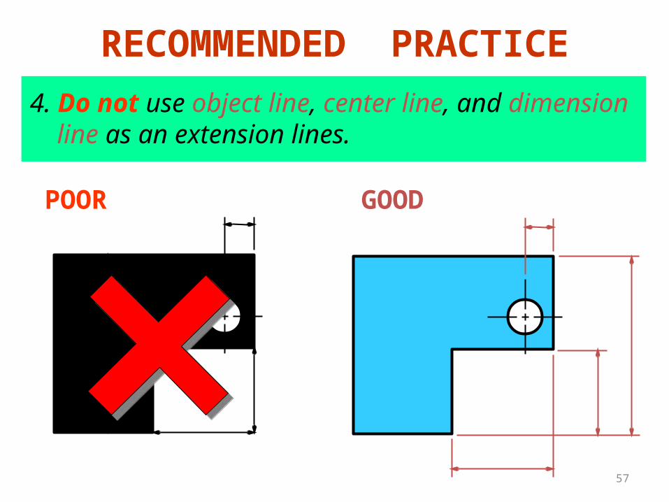
4. Do not use object line, center line, and dimension
line as an extension lines.POOR GOOD
RECOMMENDED PRACTICE
58
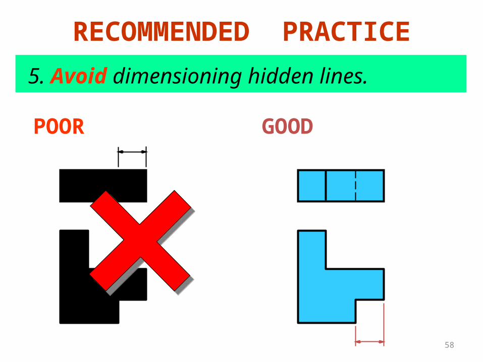
POOR GOOD
5. Avoid dimensioning hidden lines.
RECOMMENDED PRACTICE
59
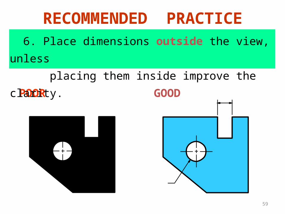
POOR GOOD
6. Place dimensions outside the view, unless
placing them inside improve the clarity.
RECOMMENDED PRACTICE
60
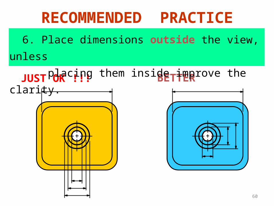
JUST OK !!! BETTER
RECOMMENDED PRACTICE 6. Place dimensions outside the view, unless
placing them inside improve the clarity.
61
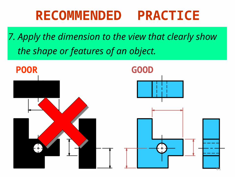
7. Apply the dimension to the view that clearly show
the shape or features of an object.
POOR GOOD
RECOMMENDED PRACTICE
62
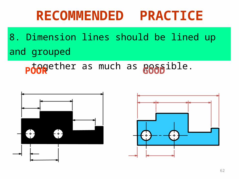
8. Dimension lines should be lined up and grouped
together as much as possible.
POOR GOOD
RECOMMENDED PRACTICE
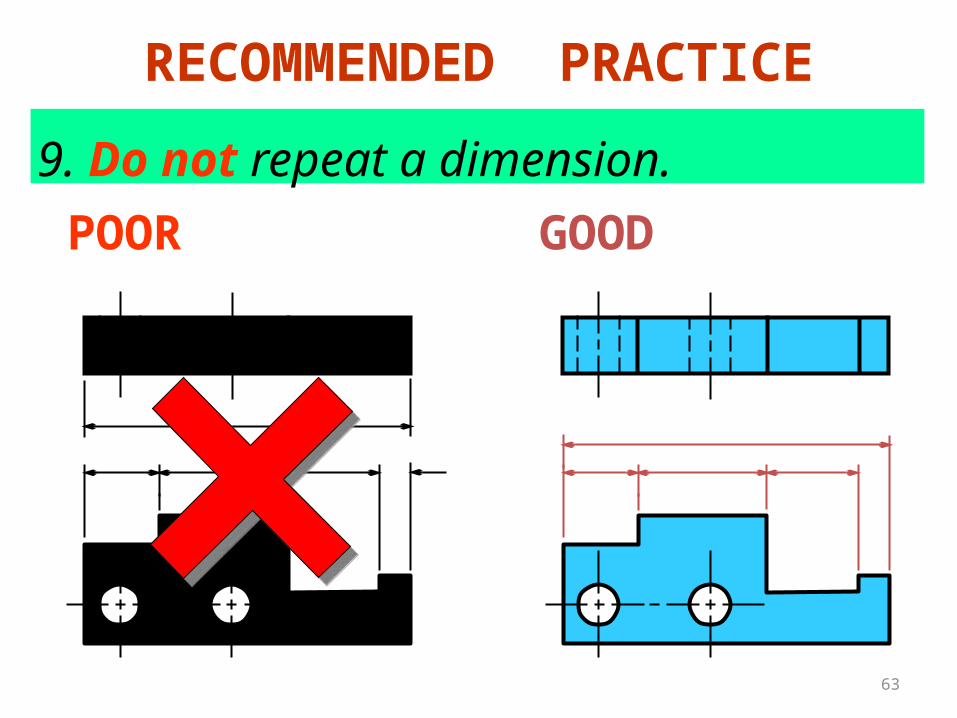
63
9. Do not repeat a dimension.
POOR GOOD
RECOMMENDED PRACTICE


