117
DIN EN ISO 9001 certified Technical support: +49 (0)7223 / 9493-0 Technical description ADDINUM APCI-/CPCI-1500 Digital inputs and outputs for the PCI / CompactPCI bus 9 th edition 04/2002

DIN EN ISO 9001
certified
Technical support:+49 (0)7223 / 9493-0
Technical description
ADDINUM APCI-/CPCI-1500
Digital inputs and outputs for the PCI / CompactPCI bus
9th edition 04/2002

Copyright
All rights reserved. This manual is intended for the manager and its personnel. No part of this publication may be reproduced or transmitted by any means. Offences can have penal consequences.
Guarantee and responsibility
Basically are effective our "general terms of delivery and payment". The manager receives them at the latest with the invoice. Claims for guarantee and responsibility in case of injuries and material damages are excluded, if they are due to one or some of the following causes: - if the board has not been used for the intended purpose - improper installation, operation and maintenance of the board - if the board has been operated with defective safety devices or with not appropriate or non-functioning safety equipment - non-observance of the instructions concerning: transport, storage, inserting the board, use, limit values, maintenance, device drivers - altering the board at the user's own initiative - altering the source files at the user's own initiative - not checking properly the parts which are subject to wear - disasters caused by the intrusion of foreign bodies and by influence beyond the user's control.
Licence for ADDI-DATA software products
Read carefully this licence before using the standard software. The right for using this software is given to the customer, if he/she agrees to the conditions of this licence. - this software can only be used for configuring ADDI-DATA boards. - copying the software is forbidden (except for archiving/ saving data and for replacing defective data carriers). - deassembling, decompiling, decoding and reverse engineering of the software are forbidden. - this licence and the software can be transferred to a third party, so far as this party has purchased a board, declares to agree to all the clauses of this licence contract and the preceding owner has not kept copies of the software.
Trademarks
Borland C and Turbo Pascal are registered trademarks of Borland International, INC. Intel is a registered trademark of Intel Corporation AT, IBM, ISA and XT are registered trademarks of International Business Machines Corporation Microsoft, MS-DOS, Visual Basic and Windows are registered trademarks of Microsoft Corporation The original version of this manual is in German. You can obtain it on request.

i
WARNING
In case of improper handling and if the board is not used for the purpose it is intended for:
people may be the board, PC and the environment injured peripheral devices may be may be damaged polluted
Protect yourself, other people and the environment
• Read the yellow safety leaflet carefully !
If this leaflet is not with the documentation, please contact us.
• Observe the instructions in the manual !
Make sure that you do not forget or skip any step. We are not liable for damage resulting from a wrong use of the board.
• Symbols used
WARNING! designates a possibly dangerous situation. If the instructions are ignored the board, PC and/or peripheral devices may be damaged.
IMPORTANT! designates hints and other useful information.
• Do you have any questions?
Our technical support is at your disposal
iii
Declaration of Conformity This declaration is valid for the following product:
ADDINUM APCI-/CPCI-1500 PCI-board for 32-bit data bus
16 digital inputs, (14 interruptible) 16 digital outputs, 24V, opto-isolated
It is made by
ADDI-DATA GmbH Meß- und Steuerungstechnik
Dieselstraße 3 D-77833 Ottersweier
in sole responsibility and is valid on the understanding that the product is competently installed, used and maintained, according to the respective security regulations as well as to the manufacturer's instructions
regarding its intended use.
This declaration states that the product complies with following EC Directives:
EWGRL 336/89 of 3.05.1989 EWGRL 31/92 of 28.04.1992 EWGRL 68/93 of 22.07.1993
This declaration is valid for all units manufactured according to the manufacturing references listed in the form TDI1500.020.
Following norms have been applied to test the product regarding electromagnetic compatibility:
EN55011/1998 EN55022/1998 EN61000-6-2/1999
We point out that
the conformity and herewith the permission of use expire if the user alters the product without consulting with the manufacturer.
non-skilled users are to have the operational area of the product and the requirements resulting from it checked prior to putting into operation.
by using this product in appliances coming under the EC EMC Directive, the user is to make sure they are conform to its regulations prior to putting into operation.
by using this product in machines / installations coming under the EU Machine Directive, the user is to make sure they are conform to its regulations prior to putting into operation.
A copy of the EMC tests is at your disposal on request.
APCI-1500: 10th June 1998 CPCI-1500: 27th July 2000
Antonio Agnetti Legally valid signature of the manufacturer

Table of contents APCI-/CPCI-1500
I
1 INTENDED PURPOSE OF THE BOARD.....................................................1
1.1 Limits of use..........................................................................................................1
2 USER ...................................................................................................2
2.1 Qualification ........................................................................................................2
2.2 Personal protection..............................................................................................2
3 HANDLING THE BOARD ........................................................................3
4 TECHNICAL DATA.................................................................................4
4.1 Electromagnetic compatibility (EMC) ..................................................................4
4.2 Physical set-up of the board................................................................................4
4.3 Options .................................................................................................................5
4.4 Limit values...........................................................................................................5
4.5 Component scheme.............................................................................................8
5 INSTALLATION....................................................................................10
5.1 Installing an APCI-1500 board...........................................................................11 5.1.1 Selecting a free slot ...................................................................................................11 5.1.2 Plugging the board into the slot.................................................................................12 5.1.3 Closing the PC...........................................................................................................12
5.2 Installing a CPCI-1500 board ............................................................................13
6 SOFTWARE.........................................................................................15
6.1 Board configuration with ADDIREG.....................................................................15 6.1.1 Installing ADDIREG .....................................................................................................15 6.1.2 Program description ..................................................................................................16 6.1.3 Registering a new board ...........................................................................................20 6.1.4 Changing the registration of a board........................................................................20
6.2 Driver installation ...............................................................................................21 6.2.1 Driver installation under MS-DOS ................................................................................21 6.2.2 Driver installation under Windows 3.11 und Windows NT ............................................21 6.2.3 Driver installation under Windows XP/2000/98 ............................................................22
6.3 Installation of the software samples ..................................................................23 6.3.1 Installation under DOS ...............................................................................................23 6.3.2 Installation under Windows 3.11 and Windows NT/XP/2000/98...................................23
6.4 The ADDI-UNINSTALL program.............................................................................24 6.4.1 Installation of ADDI-UNINSTALL ....................................................................................24 6.4.2 Software uninstalling with ADDI-UNINSTALL ..................................................................24
Uninstall ADDIREG ......................................................................................................25
6.5 Software downloads from the Internet ...............................................................25

APCI-/CPCI-1500 Table of contents
II
7 CONNECTING THE PERIPHERAL..........................................................26
7.1 Connector pin assignment.................................................................................26
7.2 Connection principle .........................................................................................27
7.3 Connection examples........................................................................................27
8 FUNCTIONS OF THE BOARD ...............................................................29
8.1 Description of the board ....................................................................................29 8.1.1 Block diagrams..........................................................................................................29 8.1.2 Description.................................................................................................................30
8.2 Functions ............................................................................................................30 8.2.1 Digital input s .............................................................................................................30
Special input functions ..............................................................................................31 1) Interrupt:............................................................................................................................... 31 2) Counter ................................................................................................................................. 31
8.2.2 Digital outputs............................................................................................................32 Special functions: ......................................................................................................32
8.2.3 Interrupt .....................................................................................................................33 8.2.4 Counter/timer ............................................................................................................34
Input frequencies ......................................................................................................35 Data ..........................................................................................................................35 Option (only implemented for the APCI-1500)...........................................................35
9 STANDARD SOFTWARE .......................................................................36
9.1 Introduction........................................................................................................36
9.2 DIN 66001- Graphical symbols ..........................................................................37
9.3 Software functions (API)......................................................................................38 9.3.1 Base address and interrupt........................................................................................38
1) i_APCI1500_InitCompiler (..) ............................................................................................. 38 2) i_APCI1500_CheckAndGetPCISlotNumber (...) ................................................................ 40 3) i_APCI1500_SetBoardInformation (...) ............................................................................... 42 4) i_APCI1500_GetHardwareInformation (...) ........................................................................ 44 5) i_APCI1500_CloseBoardHandle (..) ................................................................................... 46
9.3.2 Interrupt .....................................................................................................................48 1) i_APCI1500_SetBoardIntRoutineDos (..) ........................................................................... 48 2) i_APCI1500_SetBoardIntRoutineVBDos (..) ...................................................................... 52 3) i_APCI1500_SetBoardIntRoutineWin16 (..) ....................................................................... 55 4) i_APCI1500_SetBoardIntRoutineWin32 (..) ....................................................................... 59 5) i_APCI1500_TestInterrupt (..) ............................................................................................. 66 6) i_APCI1500_ResetBoardIntRoutine (..) .............................................................................. 68
9.3.3 Kernel functions .........................................................................................................70 1) i_APCI1500_KRNL_Read16DigitalInput (...) .................................................................... 70 2) v_APCI1500_KRNL_Set16DigitalOutputOn (...) ............................................................... 71
9.3.4 Digital input channel .................................................................................................72 1) i_APCI1500_Read1DigitalInput (...) ................................................................................... 72 2) i_APCI1500_Read8DigitalInput (...) ................................................................................... 72 3) i_APCI1500_Read16DigitalInput (...) ................................................................................. 73

Table of contents APCI-/CPCI-1500
III
9.3.5 Digital input channel - events ....................................................................................74 1) i_APCI1500_SetInputEventMask (...) ................................................................................. 74 2) i_APCI1500_StartInputEvent (...)........................................................................................ 77 3) i_APCI1500_StopInputEvent (...)........................................................................................ 77
9.3.6 Digital output channel ...............................................................................................78 1) i_APCI1500_SetOutputMemoryOn (...) .............................................................................. 78 2) i_APCI1500_SetOutputMemoryOff (...) ............................................................................. 78 3) i_APCI1500_Set1DigitalOutputOn (...)............................................................................... 78 4) i_APCI1500_Set1DigitalOutputOff (...) .............................................................................. 79 5) i_APCI1500_Set8DigitalOutputOn (...)............................................................................... 80 6) i_APCI1500_Set8DigitalOutputOff (...) .............................................................................. 81 7) v_APCI1500_Set16DigitalOutputOn (...)............................................................................ 81 8) v_APCI1500_Set16DigitalOutputOff (...) ........................................................................... 82
9.3.7 Timer/counter and watchdog....................................................................................83 1) i_APCI1500_InitTimerInputClock (...)................................................................................ 83 2) i_APCI1500_InitTimerCounter1 (...)................................................................................... 84 3) i_APCI1500_InitTimerCounter2 (...)................................................................................... 85 4) i_APCI1500_InitWatchdogCounter3 (...) ............................................................................ 87 5) i_APCI1500_StartTimerCounter1(...).................................................................................. 88 6) i_APCI1500_StartTimerCounter2 (...)................................................................................. 89 7) i_APCI1500_StartCounter3 (...) .......................................................................................... 89 8) i_APCI1500_StopTimerCounter1 (...) ................................................................................. 90 9) i_APCI1500_StopTimerCounter2 (...) ................................................................................. 90 10) i_APCI1500_StopCounter3 (...)......................................................................................... 91 11) i_APCI1500_TriggerTimerCounter1 (...) .......................................................................... 91 12) i_APCI1500_TriggerTimerCounter2 (...) .......................................................................... 91 13) i_APCI1500_TriggerCounter3 (...) .................................................................................... 92 14) i_APCI1500_Watchdog (...) .............................................................................................. 92 15) i_APCI1500_ReadTimerCounter1 (...) .............................................................................. 92 16) i_APCI1500_ReadTimerCounter2 (...) .............................................................................. 93 17) i_APCI1500_ReadCounter3 (...)........................................................................................ 94
10 EXAMPLES .........................................................................................95
10.1 Initialisation........................................................................................................95 10.1.1 Initialisation of one xPCI-1500 board .........................................................................95
a) Flow chart..............................................................................................................95 b) Example in C.........................................................................................................96
10.1.2 Initialisation of several xPCI-1500 boards ...................................................................97 a) Flow chart..............................................................................................................97 b) Example in C.........................................................................................................98
10.2 Interrupt..............................................................................................................99 10.2.1 Interrupt routine..........................................................................................................99
a) Flow chart..............................................................................................................99 b) Example in C for DOS and Windows 3.1x ............................................................100 c) Example in C for Windows NT and Windows 95/98 (in asynchronous mode) .......101 d) Example for Windows NT and Windows 95/98 (in synchronous mode) ................102

APCI-/CPCI-1500 Table of contents
IV
10.2.2 Timer interrupt ..........................................................................................................103 a) Flow chart............................................................................................................103 b) Example in C for DOS ..........................................................................................104 c) Example in C for Windows 3.1x............................................................................105 d) Example in C for Windows NT/95/98 (in asynchronous mode) .............................106 e) Example in C for Windows NT/95/98 (in synchronous mode) ...............................107
INDEX ..........................................................................................................A
Figures and tables APCI-/CPCI-1500
V
Figures
Fig. 3-1: Correct handling of the CPCI-1500 ..........................................................................3 Fig. 3-2: Correct handling of the APCI-1500...........................................................................3 Fig. 4-1: Component scheme of the APCI-1500 board .........................................................8 Fig. 4-2: Component scheme of the CPCI-1500 board........................................................9 Fig. 5-1: Opening the blister packing ...................................................................................10 Fig. 5-2: Types of slots for PCI boards....................................................................................11 Fig. 5-3: Inserting the board..................................................................................................12 Fig. 5-4: Fastening the board at the back cover..................................................................12 Fig. 5-5: Types of slots for CompactPCI boards ....................................................................13 Fig. 5-6: Pushing a CPCI board into a rack...........................................................................13 Fig. 5-7: Connector keying ...................................................................................................14 Fig. 6-1: Installation of the ADDIREG program ......................................................................15 Fig. 6-2: ADDIREG registration program ................................................................................16 Fig. 6-3: Configuring a new board .......................................................................................18 Fig. 6-4: PCI Boards...............................................................................................................19 Fig. 6-5: Driver installation .....................................................................................................21 Fig. 6-6: Inquiry of the .inf files (German version)...................................................................22 Fig. 6-7: Installation of the samples ......................................................................................23 Fig. 6-8: Installation of the ADDI-UNINSTALL program ............................................................24 Fig. 6-9: The ADDI-UNINSTALL program..................................................................................24 Fig. 7-1: 37-pin SUB-D male connector ................................................................................26 Fig. 7-2: Connection principle of the input and output channels.........................................27 Fig. 7-3: Connection examples for the input and output channels......................................27 Fig. 7-4: Connection examples............................................................................................28 Fig. 8-1: Block diagram of the APCI-1500.............................................................................29 Fig. 8-2: Block diagram of the CPCI-1500 ............................................................................29 Fig. 8-3: Protection circuitry for the inputs .............................................................................31 Fig. 8-4: Protection circuitry for the outputs...........................................................................33
Tables
Table 9-1: Type Declaration for Dos and Windows 3.1X .......................................................36 Table 9-2: Type Declaration for Windows 95/98/NT ...............................................................36 Table 9-3: Interrupt mask ......................................................................................................49

Technical description Chapter 1 APCI-/CPCI-1500
1
1 INTENDED PURPOSE OF THE BOARD
The APCI-/CPCI-1500 board is the interface between an industrial process and a personal computer (PC). It is to be used in a free PCI slot. The PC is to comply with the EU directive 89/336/EEC and the specifications for EMC protection.
Products complying with these specifications bear the mark.
Data exchange between the APCI-/CPCI-1500 board and the peripheral is to occur through a shielded cable. It has to be connected to the 37-pin SUB-D male connector of the APCI-/CPCI-1500 board.
The board has 16 input channels and 16 output channels for processing digital 24 V signals.
An external 24 V supply voltage is necessary to run the output channels. The PX 901 screw terminal board and the PX 8500 relay board allow to connect the 24 V supply voltage through a shielded cable.
The use of the APCI-/CPCI-1500 board in combination with external screw terminal or relay boards is to occur in a closed switch cabinet; the installation is to be effected competently. Check the shielding capacity of the PC housing and of the cable prior to putting the device into operation.
The connection with our standard cable ST010 complies with the specifications: - metallized plastic hoods - shielded cable - cable shield folded back and firmly screwed to the connector housing.
Uses beyond these specifications are not allowed. The manufacturer is not liable for any damages which would result from the non-observance of this clause.
The use of the board according to its intended purpose includes observing all advises given in this manual and in the safety leaflet.
1.1 Limits of use
The use of the board in a PC could change the PC features regarding noise emission and immunity. Increased noise emission or decreased noise immunity could result in the system not being conform anymore.
Our boards are not to be used for securing emergency stop functions.
The emergency stop functions are to be secured separately. This securing must not be influenced by the board or the PC.
Make sure that the board remains in the protective blister pack until it is used.
Do not remove or alter the identification numbers of the board. If you do, the guarantee expires.

APCI-/CPCI-1500 Technical description Chapter 2
2
2 USER
2.1 Qualification
Only persons trained in electronics are entitled to perform the following works:
• installation, • use, • maintenance.
2.2 Personal protection
Consider the country-specific regulations about
• the prevention of accidents • electrical and mechanical installations • radio interference suppression.

Technical description Chapter 3 APCI-/CPCI-1500
3
3 HANDLING THE BOARD
Fig. 3-1: Correct handling of the CPCI-1500
Fig. 3-2: Correct handling of the APCI-1500

APCI-/CPCI-1500 Technical description Chapter 4
4
4 TECHNICAL DATA
4.1 Electromagnetic compatibility (EMC)
The board has been subjected to EMC tests in an accredited laboratory in accordance with the norms EN50082-2, EN55011, EN55022 The board complies as follows with the limit values set by the norm EN50082-2: True value Set value ESD ................................................................... 4 kV 4 kV Fields ................................................................. 10 V/m 10 V/m Burst .................................................................. 2 kV 2 kV Conducted radio interferences........................... 10 V 10 V
WARNING! The EMC tests have been carried out in a specific appliance configuration. We guarantee these limit values only in this configuration.
Consider the following aspects: - your test program must be able to detect operation errors. - your system must be set up so that you can find out what caused errors.
4.2 Physical set-up of the board
The board is assembled on a 4-layer printed circuit card.
APCI-1500 CPCI-1500
Dimensions
131 mm
127 mm
Weight 160 g 200 g
Installation PCI-5V (32-bit) slot or PCI-5V (64-bit) slot
CompactPCI-5V(32-bit) slot or CompactPCI-5V (64-bit) slot
Connection to the peripheral
37-pin SUB-D male connector 37-pin SUB-D male connector

Technical description Chapter 4 APCI-/CPCI-1500
5
4.3 Options
The board CPCI-1500 is available in 2 versions: - CPCI-1500-3U: 3U front plane - CPCI-1500-6U: 6U front plane
4.4 Limit values
Operating temperature: ..................................... 0 to 60°C Storage temperature: ......................................... -25 to 70°C Relative humidity: ............................................ 30% to 99% non condensing
Minimum PC requirements (APCI-1500): - PCI BIOS - operating system: ........................................... MS DOS 3.3 or > Windows 3.1, NT, 95, 98 - bus speed: ....................................................... < 33 MHz
Minimum system requirements (CPCI-1500): - 32-bit CompactPCI bus (5 V) - PCI BIOS, PCI 2.1 specification and complying with CompactPCI 2.1 - operating system .............................................MS DOS 3.3 or > Windows 3.1, NT, 95, 98 - bus speed .........................................................≤ 33 MHz
Energy requirements - operating voltage of the PC: ........................... 5V ± 5% - current consumption in mA (without load): ... typ. See table ± 10%
APCI-1500 CPCI-1500
+ 5 V of the PC 320 mA 250 mA
+ 24 V extern - 10 mA
24 V digital input channels Input type: ......................................................... common ground according to IEC1131-2 Number of input channels: ............................... 16 Nominal voltage: .............................................. 24 VDC Input current at nominal voltage: ..................... 6 mA

APCI-/CPCI-1500 Technical description Chapter 4
6
Logic input level:............................................... APCI-1500 CPCI-1500 UH 1) max.: 30 V 30 V UH min.: 19 V 17 V UL2) max.: 17 V 15 V UL min.: 0 V 0 V Signal delay: ..................................................... 70 µs, (at nominal voltage) Maximum input frequency: .............................. 5 kHz (at nominal voltage)
24 V digital output channels Output type: ...................................................... high side (load at ground) Number of output channels: ............................. 16 Nominal voltage: .............................................. 24 VDC Range of the supply voltage: ............................ 10 V to 36 VDC (over 24 V ext. pins) Max. output current for the 16 output channels: ........................................... 3 A typ. (fused through PTC resistors) Max. output current / output channel: .............. 500 mA Short-circuit current / output channel at 24 V, APCI-1500: Rload < 0,1 R: ............................ 1,5 A max. (switches off the output channel) CPCI-1500: Rload < 0,01 R: .......................... 2,5 A max. (switches off the output channel) ON-resistor of the output channel (RDS ON resistor):............................................ 0,4 R max. Overtemperature: .............................................. 170°C (switches off the component i.e. the 4 output channels) Temperature hysteresis: .................................... 20°C Switch ON time at 24 V, Rload 500 mA: ........... 100 µs typ. Switch OFF time at 24 V, Rload 500 mA: ......... 60 µs typ.
Interruptible diagnostics, read back through status bit ϑ -diagnostic: ................................................... Pin 19 (24V/10 mA) is switched on in case of overload of the outputs or overtemperature Vcc-diagnostic: .................................................. is switched on in case of voltage drop < 5 V
1 UH: input voltage (= logic "1") 2 UL: input voltage (= logic "0")
Technical description Chapter 4 APCI-/CPCI-1500
7
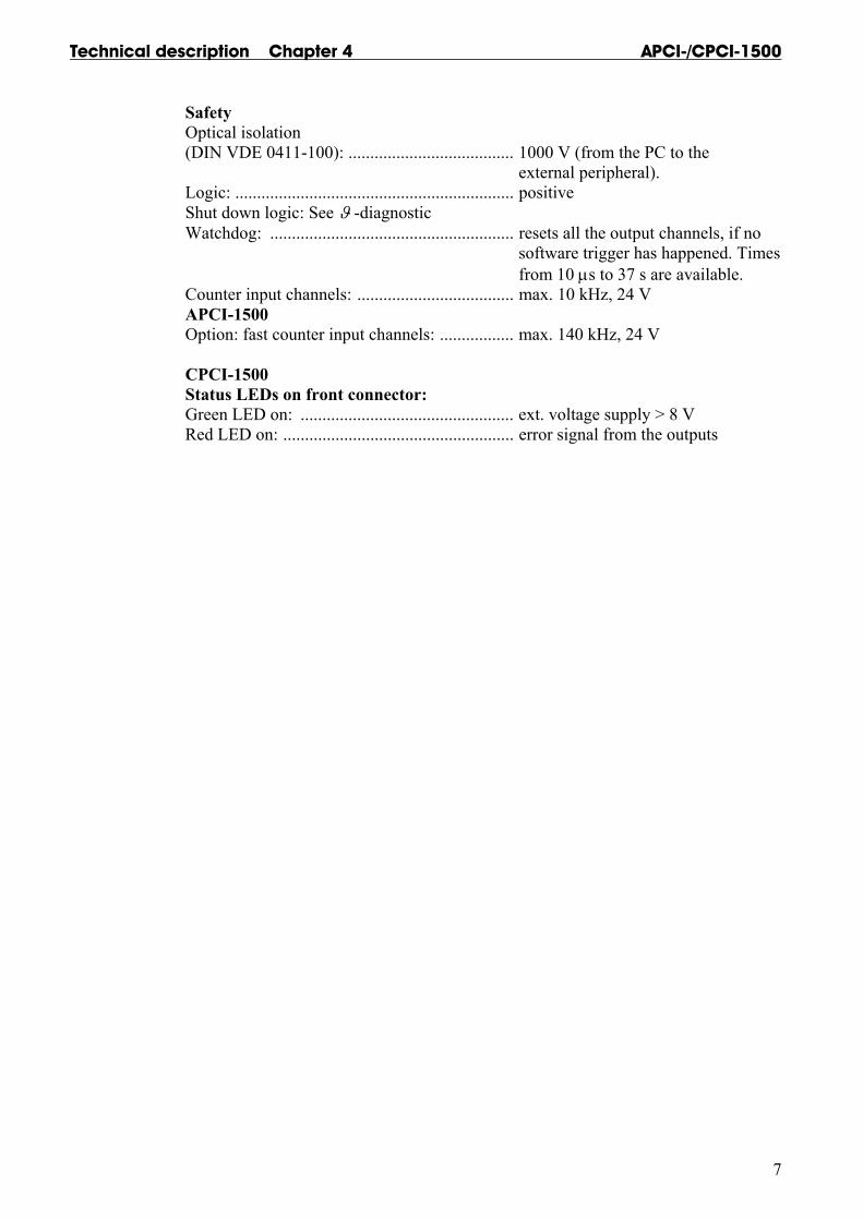
Safety Optical isolation (DIN VDE 0411-100): ...................................... 1000 V (from the PC to the external peripheral). Logic: ................................................................ positive Shut down logic: See ϑ -diagnostic Watchdog: ........................................................ resets all the output channels, if no software trigger has happened. Times from 10 µs to 37 s are available. Counter input channels: .................................... max. 10 kHz, 24 V APCI-1500 Option: fast counter input channels: ................. max. 140 kHz, 24 V CPCI-1500 Status LEDs on front connector: Green LED on: ................................................. ext. voltage supply > 8 V Red LED on: ..................................................... error signal from the outputs
APCI-/CPCI-1500 Technical description Chapter 4
8
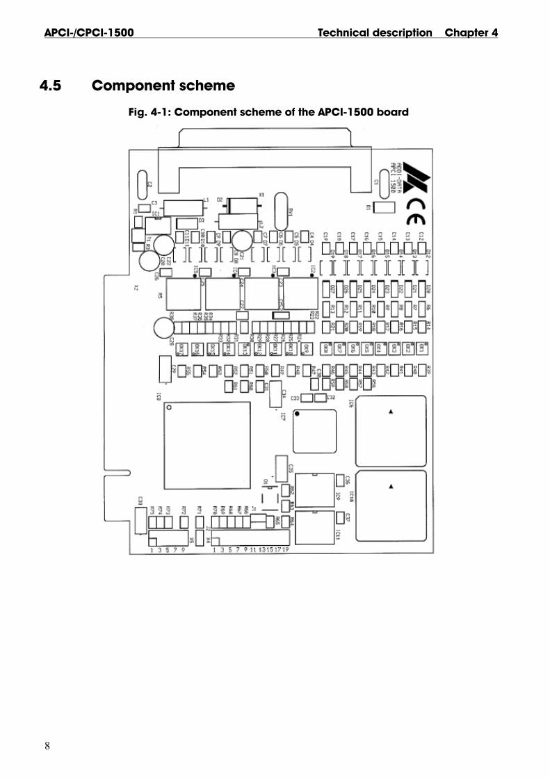
4.5 Component scheme
Fig. 4-1: Component scheme of the APCI-1500 board

Technical description Chapter 4 APCI-/CPCI-1500
9
Fig. 4-2: Component scheme of the CPCI-1500 board

APCI-/CPCI-1500 Technical description Chapter 5
10
5 INSTALLATION
IMPORTANT ! If you want to install several ADDI-DATA boards simultaneously, consider the following procedure:
• Install and configure the boards one after the other. You will thus avoid configuration errors.
• Install and configure the boards one after the other. You will thus avoid configuration errors.
1. Switch off the PC 2. Install the first board 3. Start the PC 4. Install ADDIREG (once is enough) 5. Configure the board
6. Install the driver and the samples if necessary
7. Switch off the PC 8. Install the second board 9. Start the PC 10. Configure the board 11. Install the driver and the samples if necessary. etc.
IMPORTANT! To install the new version of ADDIREG, please uninstall first the current version from your PC with the ADDI-UNINSTALL program.
Take the board out of the protective blister packing.
Fig. 5-1: Opening the blister packing
Technical description Chapter 5 APCI-/CPCI-1500
11
IMPORTANT! Do observe the safety instructions.
• Switch off your PC and all the units connected to the PC. • Pull the PC mains plug from the socket. • Open your PC as described in the manual of the PC manufacturer.
5.1 Installing an APCI-1500 board
5.1.1 Selecting a free slot
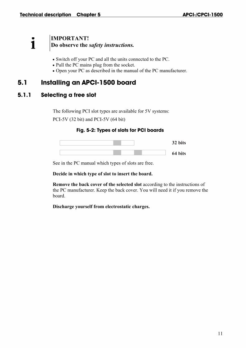
The following PCI slot types are available for 5V systems:
PCI-5V (32 bit) and PCI-5V (64 bit)
Fig. 5-2: Types of slots for PCI boards
See in the PC manual which types of slots are free.
Decide in which type of slot to insert the board.
Remove the back cover of the selected slot according to the instructions of the PC manufacturer. Keep the back cover. You will need it if you remove the board.
Discharge yourself from electrostatic charges.

APCI-/CPCI-1500 Technical description Chapter 5
12
5.1.2 Plugging the board into the slot
• Discharge yourself from electrostatic charges • Insert the board vertically into the chosen slot.
Fig. 5-3: Inserting the board
• Fasten the board to the rear of the PC housing with the screw which was fixed on the back cover.
Fig. 5-4: Fastening the board at the back cover
• Tighten all the loosen screws.
5.1.3 Closing the PC
Close your PC as described in the manual of the PC manufacturer.

Technical description Chapter 5 APCI-/CPCI-1500
13
5.2 Installing a CPCI-1500 board
The following Compact PCI slot types are available for 5V systems: CPCI-5V (32-bit) and CPCI-5V (64-bit)
See in the computer manual which types of slots are free.
Fig. 5-5: Types of slots for CompactPCI boards
• Discharge yourself from electrostatic charges as described in the leaflet
"Safety precautions”.
• Hold the board at its grip (See board handling in chapter 3).
• Insert the board into the guiding rails and push it to the back cover of the rack. In order to fully insert the board, a small resistance has to be overcome.
Fig. 5-6: Pushing a CPCI board into a rack
• Make sure that the board is correctly connected by connecting the key of the board to the key of the backplane (blue key connectors if the board operates with 5 V)
APCI-/CPCI-1500 Technical description Chapter 5
14
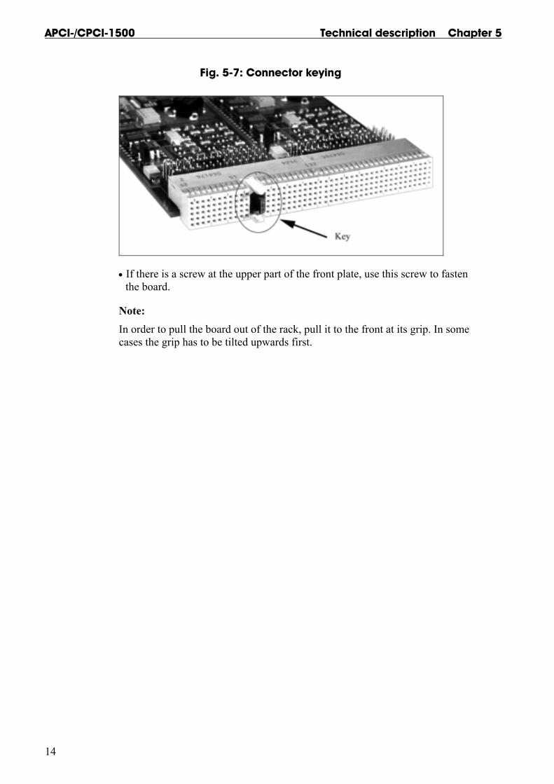
Fig. 5-7: Connector keying
• If there is a screw at the upper part of the front plate, use this screw to fasten the board.
Note: In order to pull the board out of the rack, pull it to the front at its grip. In some cases the grip has to be tilted upwards first.
Technical description Chapter 6 APCI-/CPCI-1500
15
6 SOFTWARE
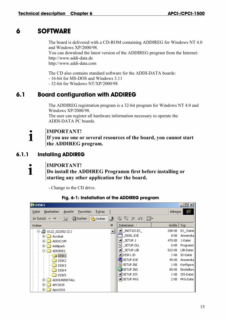
The board is delivered with a CD-ROM containing ADDIREG for Windows NT 4.0 and Windows XP/2000/98. You can download the latest version of the ADDIREG program from the Internet: http://www.addi-data.de http://www.addi-data.com
The CD also contains standard software for the ADDI-DATA boards: - 16-bit for MS-DOS and Windows 3.11 - 32-bit for Windows NT/XP/2000/98
6.1 Board configuration with ADDIREG
The ADDIREG registration program is a 32-bit program for Windows NT 4.0 and Windows XP/2000/98. The user can register all hardware information necessary to operate the ADDI-DATA PC boards.
IMPORTANT! If you use one or several resources of the board, you cannot start the ADDIREG program.
6.1.1 Installing ADDIREG
IMPORTANT! Do install the ADDIREG Programm first before installing or starting any other application for the board.
- Change to the CD drive.
Fig. 6-1: Installation of the ADDIREG program

APCI-/CPCI-1500 Technical description Chapter 6
16
- Start the set-up program "setup.exe" (double click) - Select one of the 3 parameters 1- typical 2- compact 3- custom Proceed as indicated on the screen and read attentively the "Software License" and "Readme". In "custom", you can select your operating system.
The installation program gives you further instructions.
If the message "Der Keyboard Kernel wurde noch nicht gestartet, ... soll der Kernel jetzt gestartet werden?" (Problem when installing the system) is displayed by starting the program, deinstall the ADDIREG program and install it anew.
6.1.2 Program description
IMPORTANT! Insert the ADDI-DATA boards to be registered before starting the ADDIREG program.
If the board is not inserted, the user cannot test the registration. Once the program is called up, the following dialog box appears.
Fig. 6-2: ADDIREG registration program
Board name: Names of the different registered boards. When you start the program for the first time, no board is registered in this table.
Base address: Selected base address of the board.

Technical description Chapter 6 APCI-/CPCI-1500
17
Access: Selection of the access mode for the ADDI-DATA digital boards. Access in 8-bit or 16-bit.
PCI bus/device/(slot): Used PCI slot. If the board is no PCI board, the message "NO" is displayed.
Interrupt: Used interrupt of the board. If the board uses no interrupt, the message "Not available" is displayed.
DMA: Indicates the selected DMA channel or "Not available" if the board uses no DMA.
More information: Additional information like the identifier string (e.g.: PCI1500-50) or the installed COM interfaces.
Text boxes: Under the table you will find 6 text boxes in which you can change the parameters of the board.
Base address name: Description of the used base addresses for the board. Select a name though the pull-down menu. The corresponding address range is displayed in the field below (Base address).
Interrupt name: Description of the used IRQ lines for the board. Select a name though the pull-down menu. The corresponding interrupt line is displayed in the field below (Interrupt).
DMA name (for ISA board only): When the board supports 2 DMA channels, you can select which DMA channel is to be changed.
DMA channel (for ISA board only): Selection of the used DMA channel.
APCI-/CPCI-1500 Technical description Chapter 6
18
Buttons: Edit 1: Selection of the highlighted board with the different parameters set in the text boxes. Click on "Edit" to activate the data or click twice on the selected board.
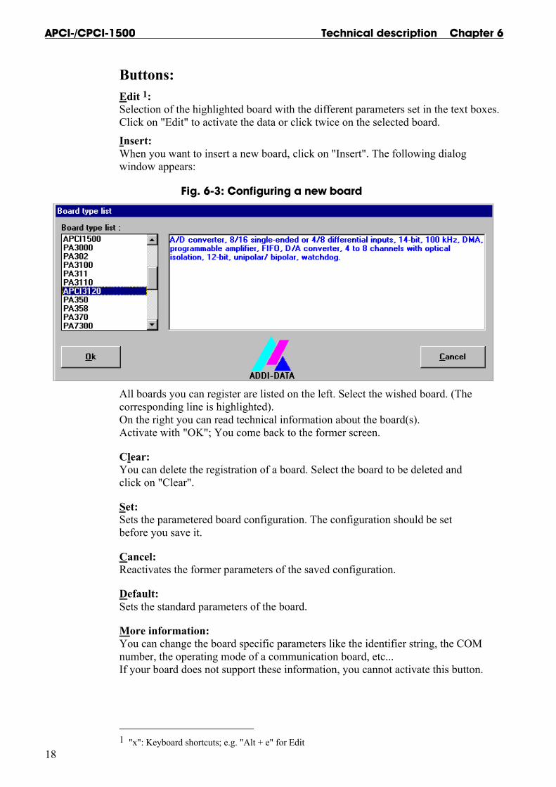
Insert: When you want to insert a new board, click on "Insert". The following dialog window appears:
Fig. 6-3: Configuring a new board
All boards you can register are listed on the left. Select the wished board. (The corresponding line is highlighted). On the right you can read technical information about the board(s). Activate with "OK"; You come back to the former screen.
Clear: You can delete the registration of a board. Select the board to be deleted and click on "Clear".
Set: Sets the parametered board configuration. The configuration should be set before you save it.
Cancel: Reactivates the former parameters of the saved configuration.
Default: Sets the standard parameters of the board.
More information: You can change the board specific parameters like the identifier string, the COM number, the operating mode of a communication board, etc... If your board does not support these information, you cannot activate this button.
1 "x": Keyboard shortcuts; e.g. "Alt + e" for Edit
Technical description Chapter 6 APCI-/CPCI-1500
19
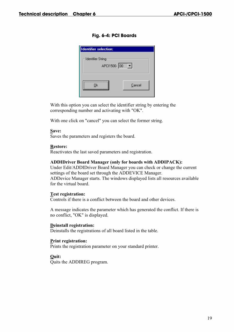
Fig. 6-4: PCI Boards
With this option you can select the identifier string by entering the corresponding number and activating with "OK".
With one click on "cancel" you can select the former string.
Save: Saves the parameters and registers the board.
Restore: Reactivates the last saved parameters and registration.
ADDIDriver Board Manager (only for boards with ADDIPACK): Under Edit/ADDIDriver Board Manager you can check or change the current settings of the board set through the ADDEVICE Manager. ADDevice Manager starts. The windows displayed lists all resources available for the virtual board.
Test registration: Controls if there is a conflict between the board and other devices.
A message indicates the parameter which has generated the conflict. If there is no conflict, "OK" is displayed.
Deinstall registration: Deinstalls the registrations of all board listed in the table.
Print registration: Prints the registration parameter on your standard printer.
Quit: Quits the ADDIREG program.

APCI-/CPCI-1500 Technical description Chapter 6
20
6.1.3 Registering a new board
IMPORTANT! To register a new board, you must have administrator rights. Only an administrator is allowed to register a new board or change a registration.
• Call up the ADDIREG program. The Fig. 6-2 is displayed on the screen. Click on "Insert". Select the wished board.
• Click on "OK". The default address, interrupt, and the other parameters are automatically set in the lower fields. The parameters are listed in the lower fields. If the parameters are not automatically set by the BIOS, you can change them. Click on the wished scroll function(s) and choose a new value. Activate your selection with a click.
• Once the wished configuration is set, click on "Set".
• Save the configuration with "Save".
• You can test if the registration is "OK". This test controls if the registration is right and if the board is present. If the test has been successfully completed you can quit the ADDIREG program. The board is initialised with the set parameters and can now be operated. In case the registration data is to be modified, it is necessary to boot your PC again. A message asks you to do so. When it is not necessary you can quit the ADDIREG program and directly begin with your application.
6.1.4 Changing the registration of a board
IMPORTANT! To change the registration of a board, you must have administrator rights. Only an administrator is allowed to register a new board or change a registration.
• Call up the ADDIREG program. Select the board to be changed. The board parameters (Base address, DMA channel, ..) are listed in the lower fields.
• Click on the parameter(s) you want to set and open the scroll function(s).
• Select a new value. Activate it with a click. Repeat the operation for each parameter to be modified.
• Once the wished configuration is set, click on "Set".
• Save the configuration with "Save".
• You can test if the registration is "OK". This test controls if the registration is right and if the board is present. If the test has been successfully completed you can quit the ADDIREG program. The board is initialised with the set parameters and can now be operated.
In case the registration data is to be modified, it is necessary to boot your PC again. A message asks you to do so. When it is not necessary you can quit the ADDIREG program and directly begin with your application.

Technical description Chapter 6 APCI-/CPCI-1500
21
6.2 Driver installation
Remark: The CPCI-1500 board is entirely compatible with the APCI-1500 board regarding the software installation and the device driver. The program ADDIREG will thus make no difference between the systems (PCI board or Compact PCI board). The API functions of the device driver are also the same.
6.2.1 Driver installation under MS-DOS
- Copy the contents of APCI1500\Dos\Disk1 or on a disk. If several disks are to be used, the directory content is stored in several sub- directories (Disk1, Disk2, Disk3...). - Insert the (first) disk into a driver and change to this drive. - Enter <INSTALL>.
The installation program gives you further instructions.
6.2.2 Driver installation under Windows 3.11 und Windows NT
- Change to the CD drive.
Fig. 6-5: Driver installation
- Select the directory APCI1500\Win-XP-2000-NT-98\driver\Disk1 or APCI1500\Win311\driver\Disk1. - Start the set-up program "setup.exe" (double click) - Select one of the 3 parameters 1- typical 2- compact 3- custom Proceed as indicated on the screen and read attentively the "Software License" and "Readme". In "custom", you can select your operating system. The installation program gives you further instructions.
APCI-/CPCI-1500 Technical description Chapter 6
22
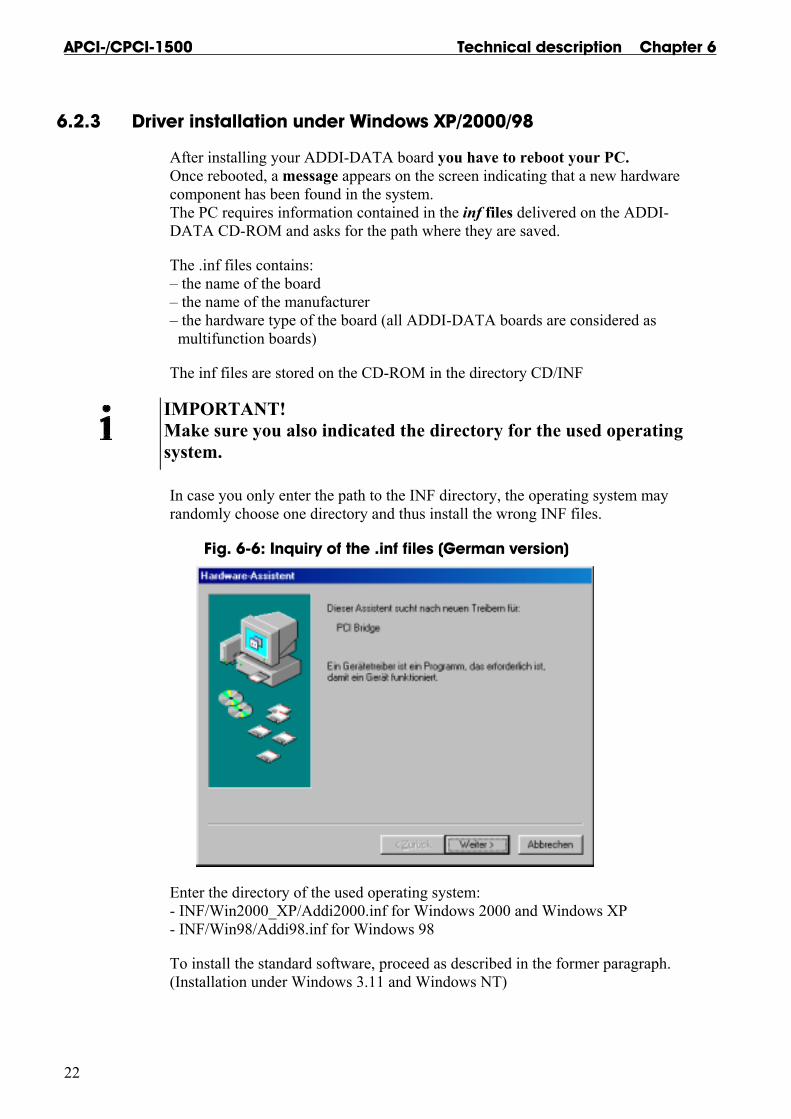
6.2.3 Driver installation under Windows XP/2000/98
After installing your ADDI-DATA board you have to reboot your PC. Once rebooted, a message appears on the screen indicating that a new hardware component has been found in the system. The PC requires information contained in the inf files delivered on the ADDI-DATA CD-ROM and asks for the path where they are saved.
The .inf files contains: – the name of the board – the name of the manufacturer – the hardware type of the board (all ADDI-DATA boards are considered as multifunction boards)
The inf files are stored on the CD-ROM in the directory CD/INF
IMPORTANT! Make sure you also indicated the directory for the used operating system.
In case you only enter the path to the INF directory, the operating system may randomly choose one directory and thus install the wrong INF files.
Fig. 6-6: Inquiry of the .inf files (German version)
Enter the directory of the used operating system: - INF/Win2000_XP/Addi2000.inf for Windows 2000 and Windows XP - INF/Win98/Addi98.inf for Windows 98
To install the standard software, proceed as described in the former paragraph. (Installation under Windows 3.11 and Windows NT)

Technical description Chapter 6 APCI-/CPCI-1500
23
6.3 Installation of the software samples
6.3.1 Installation under DOS
The software samples for DOS are automatically installed with the driver.
6.3.2 Installation under Windows 3.11 and Windows NT/XP/2000/98
- Change to the CD drive. The files for the required samples are to be found as follows:
Fig. 6-7: Installation of the samples
- Select the required programming language.
- Start the set-up program "setup.exe" (double click)
- Select one of the 3 parameters 1- typical: all files are installed (Samples, source code and exe files). 2- compact: only the source code is installed. 3- custom: you can select which files are to be installed.
Proceed as indicated on the screen and read attentively the "Software License" and "Readme". In "custom", you can select your operating system.
The installation program gives you further instructions.
APCI-/CPCI-1500 Technical description Chapter 6
24
6.4 The ADDI-UNINSTALL program 6.4.1 Installation of ADDI-UNINSTALL
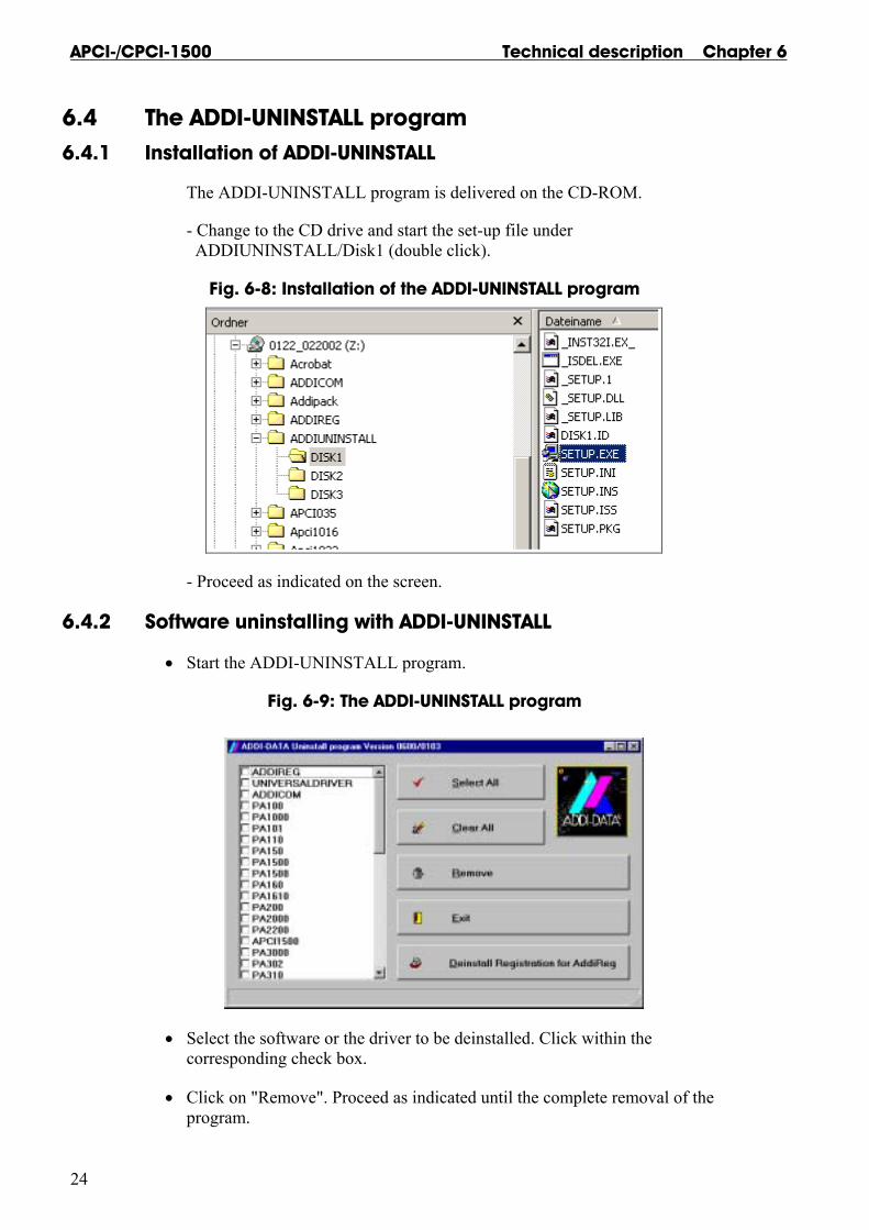
The ADDI-UNINSTALL program is delivered on the CD-ROM.
- Change to the CD drive and start the set-up file under ADDIUNINSTALL/Disk1 (double click).
Fig. 6-8: Installation of the ADDI-UNINSTALL program
- Proceed as indicated on the screen.
6.4.2 Software uninstalling with ADDI-UNINSTALL
• Start the ADDI-UNINSTALL program.
Fig. 6-9: The ADDI-UNINSTALL program
• Select the software or the driver to be deinstalled. Click within the corresponding check box.
• Click on "Remove". Proceed as indicated until the complete removal of the program.

Technical description Chapter 6 APCI-/CPCI-1500
25
Uninstall ADDIREG
• Click on "Deinstall registration for AddiReg".
Proceed as indicated until the complete removal of ADDIREG. The ADDIREG entries in the Windows registry are deleted. Removing the ADDIREG program The ADDI_UNINSTALL program is delivered on the CD-ROM.
• Install the ADDI_UNINSTALL program on your computer. • Start the ADDIREG program and click on "Deinstall registration" • Quit ADDIREG • Start the ADDI_UNINSTALL program • Proceed as indicated until the complete removing of ADDIREG.
You can also download the program from the Internet.
6.5 Software downloads from the Internet
You can download the latest version of the device driver for the APCI-/CPCI-1500 board. http://www.addi-data.de. or http://www.addi-data.com
If you have any questions, do not hesitate to send us an e-mail to [email protected] or [email protected]

Technical description Chapter 7 APCI-/CPCI-1500
26
7 CONNECTING THE PERIPHERAL
7.1 Connector pin assignment
Fig. 7-1: 37-pin SUB-D male connector

Technical description Chapter 7 APCI-/CPCI-1500
27
7.2 Connection principle
Fig. 7-2: Connection principle of the input and output channels
7.3 Connection examples
Fig. 7-3: Connection examples for the input and output channels
Technical description Chapter 7 APCI-/CPCI-1500
28
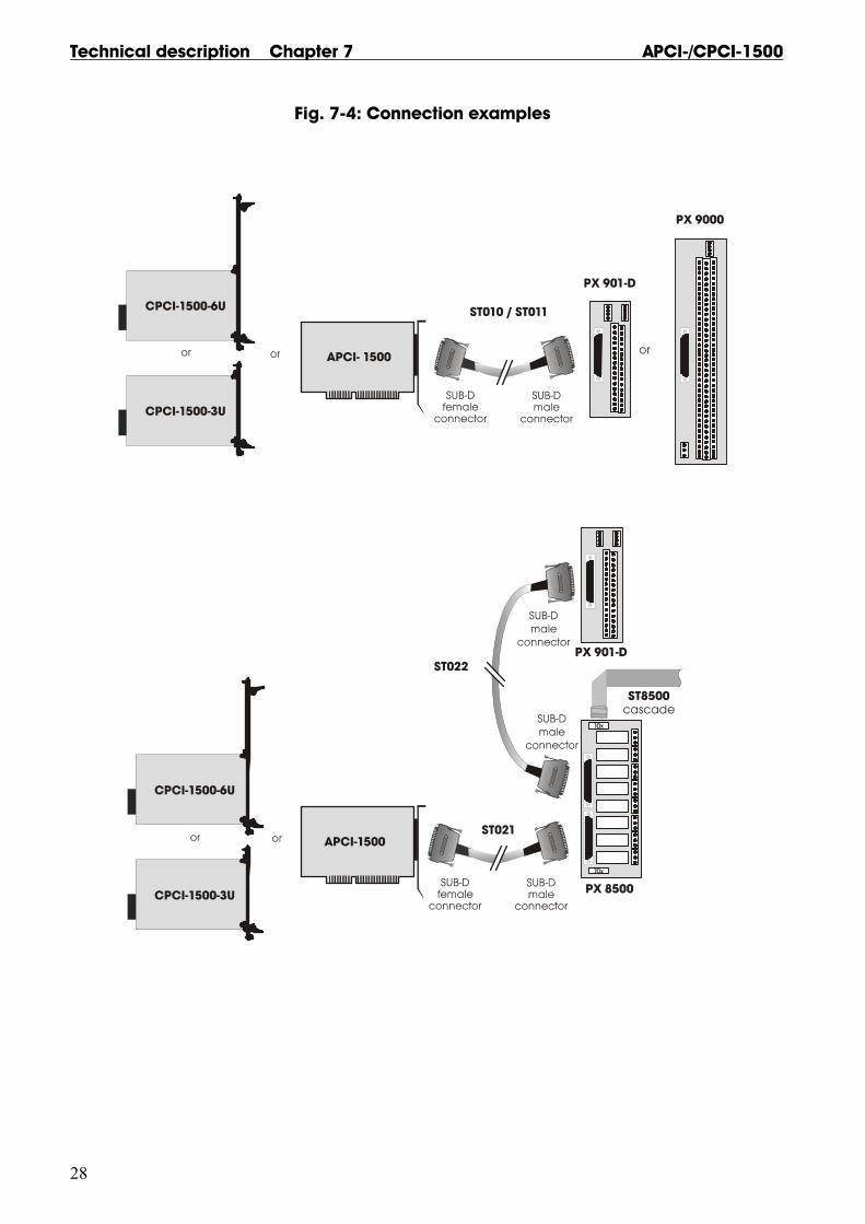
Fig. 7-4: Connection examples
Technical description Chapter 8 APCI-/CPCI-1500
29
8 FUNCTIONS OF THE BOARD
8.1 Description of the board
8.1.1 Block diagrams
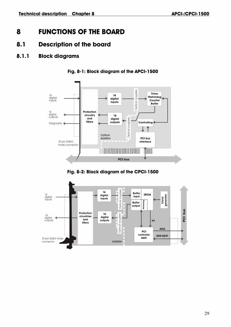
Fig. 8-1: Block diagram of the APCI-1500
Fig. 8-2: Block diagram of the CPCI-1500

Technical description Chapter 8 APCI-/CPCI-1500
30
8.1.2 Description
The board APCI-/CPCI-1500 is intended for parallel input/output for digital signals in 24 V industrial environment. The peripheral and the system have a simultaneous optical isolation.
The board offers: - 16 digital inputs: 14 are interruptible. - 3 counters (or timers): programmable by software - 1 timer: can be used as a watchdog for the outputs. - 16 digital outputs:
- short-circuit current, - protection against overtemperature, - small ON-resistor, - wide supply voltage range, - the outputs are switched off if the voltage drops below the limit value (5 V).
The base address and the interrupt lines are automatically set through the BIOS.
EMC: design in accordance with CE regulations.
8.2 Functions
8.2.1 Digital input s
WARNING! Do not operate the board simultaneously in several modes. Otherwise you may damage the board, PC and/or the peripheral.
The board APCI-/CPCI-1500 supplies 16 optically isolated inputs. The inputs comply with the 24 V industry standard (IEC1131-2):
CPCI-1500: - logic "1" corresponds to an input voltage > 17 V - logic "0" corresponds to an input voltage < 15 V. APCI-1500: - logic "1" corresponds to an input voltage > 19 V - logic "0" corresponds to an input voltage < 17 V.
All the inputs have a common current ground: 0V Ext. (inputs), pin 10 of the 37-pin SUB-D male connector.
The current input is at 6 mA with a nominal voltage of 24 V.

Technical description Chapter 8 APCI-/CPCI-1500
31
WARNING! Do you operate all inputs with the same voltage supply? The voltage supply must deliver at least 16 x 6 = 96 mA.
The maximum input voltage is 30 V.
Transil diodes, Z diodes, C filters and optical couplers protect the system bus from noise emitted by the peripheral. The effects of inductive and capacitive noise are thus reduced.
The board requires no initialisation to read the 24 V digital information. After successful power ON reset, data is immediately available on the board.
Special input functions
1) Interrupt:
The inputs 1 to 14 can generate an interrupt.
Inputs 1 to 8: It is possible to declare an OR or AND event to generate an interrupt. Inputs 9 to 14: It is possible to declare an OR event to generate an interrupt. Inputs 15 & 16: are not interruptible and are not used in events.
2) Counter
Counter 1: Input 14 signal input
Counter 2: Input 10 signal input Input 11 can be used for a "trigger" function Input 12 can be used for a "gate" function.
Counter 3 Input 15 signal input Input 16 can be used as a "gate" function.
Fig. 8-3: Protection circuitry for the inputs
Technical description Chapter 8 APCI-/CPCI-1500
32
8.2.2 Digital outputs
The board supplies 16 optically isolated outputs.
The outputs comply with the 24 V industry standard (IEC1131-2):
The positive logic is used - logic "1": sets the output by software (switch on ON), - logic "0": resets the output (switch on OFF).
The outputs switch the +24V ext. outside to the load. One end of the load is connected with the ground of 0V EXT (outputs). All outputs have a common ground: 0V ext. (outputs) pin 29 of the 37-pin SUB-D male connector.
WARNING! If you use all outputs with the same voltage supply, the voltage supply must deliver at least the power required for your application.
The maximum supply voltage is 36 V. Each output can switch 500 mA current. But the current is limited for all the outputs on approx. 3 A by a self-resetting fuse. Features of the outputs: - Short-circuit current for the 16 outputs - Protection against overtemperature: shut down logic. Each group of 4 outputs is switched off: 1 to 4, 5 to 8, 9 to 12, 13 to 16. - The outputs are switched off if the ext. supply voltage drops below 5 V. - Diagnostic report through status register or interrupt to the PC in case of short-circuit, overtemperature, voltage drop or watchdog. Transil diodes, C filters and optical couplers filter noise from the peripheral to the system bus. Thus the effects of inductive and capacitive noise are reduced. Possible noise emissions are also reduced by C filters.
The board requires no initialisation to output the 24V digital information. You can program the outputs immediately after successful power ON reset
State after power ON reset : all the outputs are reset (switch on OFF).
Special functions:
2 diagnostic bits are available on the board.
The ϑ -diagnostic (Pin 19 on the front connector) is released: - when short-circuit has occurred on an output or - in case of overtemperature on an output component (8 channels). The Vcc-diagnostic informs that: - the external voltage supply has dropped < 5 V.

Technical description Chapter 8 APCI-/CPCI-1500
33
These error data are available through an interrupt routine. See API functions: i_APCI1500_SetBoardIntRoutineXX, i_APCI1500_ResetBoardIntRoutine.
Fig. 8-4: Protection circuitry for the outputs
8.2.3 Interrupt
The board has an interrupt line. An interrupt line of the PCI bus is allocated to the board through the BIOS.
Possible interrupt sources: - Event 1 has occurred (input 1-8), - Event 2 has occurred (input 9-14), - Counter/Timer 1 has run down - Counter/Timer 2 has run down - Counter/Timer 3 has run down - Watchdog has run down, the outputs are reset, - Voltage error (the external voltage supply has dropped below 5 V), - Short-circuit error, overtemperature error. The interrupt source information are available on the user program through an interrupt routine See API functions: i_APCI1500_SetBoardIntRoutineXX, i_APCI1500_ResetBoardIntRoutine.
An event indicates a change of status (level): - on an input (ex. "0" 1") - or on several inputs if a logic has been defined between the inputs.
Running-down: if the counter changes from 1 0.

Technical description Chapter 8 APCI-/CPCI-1500
34
8.2.4 Counter/timer
On the board three 16-bit counters/timers are available in the component Z8536 (downwards counting). Each counter/timer can be programmed by software.
If the component Z8536 operates as a counter, the corresponding inputs are used as follows:
Counter Counter 1: Input 14 signal input. Counter 2: Input 10 signal input Input 11 can be used as a "trigger" function Input 12 can be used as a "gate" function. Counter 3 Input 15 signal input Input 16 can be used as a "gate" function.
Timer If the component Z8536 is used as a timer, the frequency is used as a reference. "Gate" and "trigger" are possible through the inputs.
Gate : can be driven by software or an input can be set. The polarity of the input can be programmed. This "gate" stops counting when it is set. Trigger : can be driven by software or an input can be set. The polarity of the input can be programmed. This "trigger" re-loads the counter/timer with the initial counter value.
The following functionalities are available: - Initialising the counters/timers, - Starting the counters/timers, - Stopping the counters/timers, - Reading the counter value of the counters/timers
The counter/timer 3 has a special function: Watchdog Timer. The function Watchdog Timer allows to supervise the software or PC.
The principle is: The counter/timer 3 is programmed as a non reloadable timer. The timer is started. The outputs are reset when the timer has run down (switch OFF).
The user software must be built in such a way that the output channels are always set to "ON" again. You thus avoid that the watchdog runs down.

Technical description Chapter 8 APCI-/CPCI-1500
35
Input frequencies
The input frequency for the timer is selected through the software function i_APCI1500_InitTimerInputClock (...)
Available frequencies: 111.86 kHz ± 100 ppm, 3.49 kHz ± 100 ppm, 1.747 kHz ± 100 ppm.
IMPORTANT! The timer component internally operates with half of the input frequency.
Data
Approximate watchdog times: Input frequency 17.9 µs 1175 ms 111.86 kHz 574 µs 37.65 s 3.49 kHz 1.14 ms 74.9 s 1.747 kHz
Option (only implemented for the APCI-1500)
The counter input channels 1, 2 and 3 can be equipped with fast optical couplers. The maximum input frequency is then 140 kHz. (Standard frequency: 10 kHz)

APCI-/CPCI-1500 Technical description Chapter 9
36
9 STANDARD SOFTWARE
9.1 Introduction
IMPORTANT! Note the following conventions in the text:
Function: "i_APCI1500_SetBoardAddress" Variable ui_Address
Table 9-1: Type Declaration for Dos and Windows 3.1X
Borland C Microsoft C Borland Pascal
Microsoft Visual Basic
Dos
Microsoft Visual Basic
Windows
VOID void void pointer any
BYTE unsigned char unsigned char byte integer integer
INT int int integer integer integer
UINT unsigned int unsigned int word long long
LONG long long longint long long
PBYTE unsigned char * unsigned char * var byte integer integer
PINT int * int * var integer integer integer
PUINT unsigned int * unsigned int * var word long long
PCHAR char * char * var string string string
Table 9-2: Type Declaration for Windows 95/98/NT
Borland C Microsoft C Borland Pascal
Microsoft Visual Basic
Dos
Microsoft Visual Basic
Windows
VOID void void pointer any
BYTE unsigned char unsigned char byte integer integer
INT int int integer integer integer
UINT unsigned int unsigned int long long long
LONG long long longint long long
PBYTE unsigned char * unsigned char * var byte integer integer
PINT int * int * var integer integer integer
PUINT unsigned int * unsigned int * var long long long
PCHAR char * char * var string string string
Technical description Chapter 9 APCI-/CPCI-1500
37
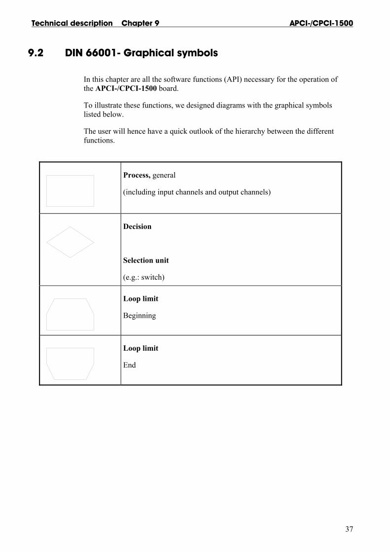
9.2 DIN 66001- Graphical symbols
In this chapter are all the software functions (API) necessary for the operation of the APCI-/CPCI-1500 board.
To illustrate these functions, we designed diagrams with the graphical symbols listed below.
The user will hence have a quick outlook of the hierarchy between the different functions.
Process, general
(including input channels and output channels)
Decision
Selection unit
(e.g.: switch)
Loop limit
Beginning
Loop limit
End

APCI-/CPCI-1500 Technical description Chapter 9
38
9.3 Software functions (API)
Remark: The CPCI-1500 board is entirely compatible with the APCI-1500 board regarding the software installation and the device driver. The program ADDIREG will thus make no difference between the systems (PCI board or Compact PCI board). The API functions of the device driver are also the same.
9.3.1 Base address and interrupt
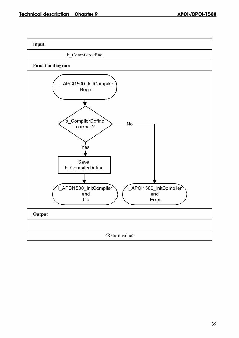
1) i_APCI1500_InitCompiler (..)
Syntax: <Return value> = i_APCI1500_InitCompiler (BYTE b_CompilerDefine)
Parameters: - Input: BYTE b_CompilerDefine The user has to choose the language under Windows in which he/she wants to program - DLL_COMPILER_C: The user programs in C. - DLL_COMPILER_VB: The user programs in Visual Basic for Windows. - DLL_COMPILER_VB_5: The user programs in Visual Basic 5 for Windows NT or Windows 95/98. - DLL_COMPILER_PASCAL: The user programs in Pascal or Delphi. - DLL_LABVIEW : The user programs in Labview. - Output: No output signal has occurred.
Task: If you want to use the DLL functions, parameter in the language which you want to program in. This function must be the first to be called up.
IMPORTANT! This function is only available with a Windows environment.
Calling convention: ANSI C : int i_ReturnValue; i_ReturnValue = i_APCI1500_InitCompiler (DLL_COMPILER_C);
Return value: 0: No error -1: Compiler parameter is wrong
Technical description Chapter 9 APCI-/CPCI-1500
39
Input
b_Compilerdefine
Function diagram
i_APCI1500_InitCompilerBegin
b_CompilerDefine correct ?
i_APCI1500_InitCompiler endOk
i_APCI1500_InitCompiler end Error
Yes
No
Save b_CompilerDefine
Output
<Return value>

APCI-/CPCI-1500 Technical description Chapter 9
40
2) i_APCI1500_CheckAndGetPCISlotNumber (...)
Syntax: <Return value> = i_APCI1500_CheckAndGetPCISlotNumber (PBYTE pb_SlotNumberArray)
Parameters: - Input: No input signal has to occur. - Output: PBYTE pb_SlotNumberArray List of the slot numbers.
Task: Checks all xPCI-15001 and returns the slot number of each xPCI-1500 board. Each pb_SlotNumberArray parameter contains the slot number (1 to 10) of one xPCI-1500 board.
Calling convention: ANSI C : int i_ReturnValue; unsigned char b_SlotNumberArray [10]; i_ReturnValue = i_APCI1500_CheckAndGetPCISlotNumber (b_SlotNumberArray);
Return value: Returns the number of xPCI-1500 boards which are inserted in your PC. If the return value equals 0 then no xPCI-1500 board was found in your PC.
1 Common designation for the boards APCI-1500 and CPCI-1500

Technical description Chapter 9 APCI-/CPCI-1500
41
Input
Function diagram
i_APCI1500_CheckAndGetPCISlotNumberBegin
APCI-1500 Board ?
Yes
i_APCI1500_CheckAndGetPCISlotNumberReturns the number of APCI-1500
Search next PCI board
PCIboard found?
Yes
No
No
- Save slot number- Save base address- Save interrupt
Output
pb_SlotNumberArray
<Return value>
APCI-/CPCI-1500 Technical description Chapter 9
42
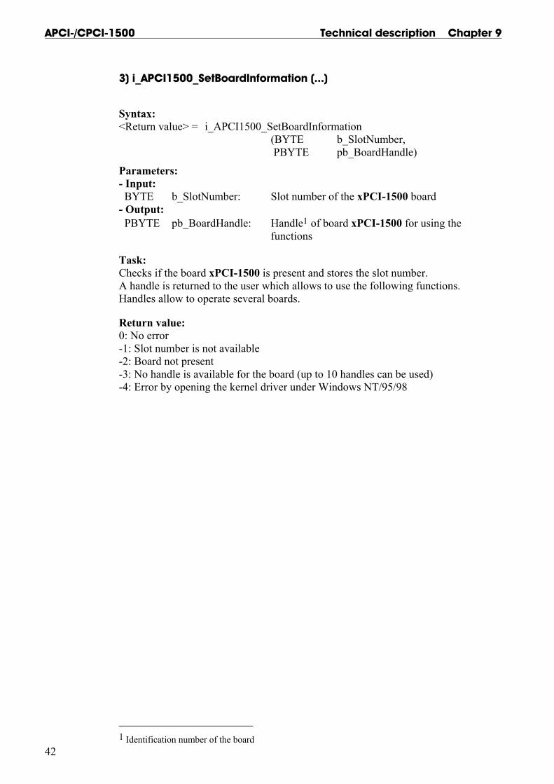
3) i_APCI1500_SetBoardInformation (...)
Syntax: <Return value> = i_APCI1500_SetBoardInformation (BYTE b_SlotNumber, PBYTE pb_BoardHandle)
Parameters: - Input: BYTE b_SlotNumber: Slot number of the xPCI-1500 board - Output: PBYTE pb_BoardHandle: Handle1 of board xPCI-1500 for using the functions
Task: Checks if the board xPCI-1500 is present and stores the slot number. A handle is returned to the user which allows to use the following functions. Handles allow to operate several boards.
Return value: 0: No error -1: Slot number is not available -2: Board not present -3: No handle is available for the board (up to 10 handles can be used) -4: Error by opening the kernel driver under Windows NT/95/98
1 Identification number of the board
Technical description Chapter 9 APCI-/CPCI-1500
43
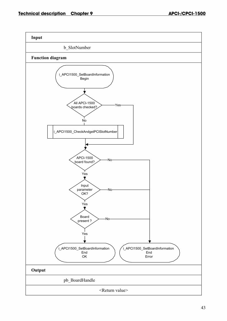
Input
b_SlotNumber
Function diagram
i_APCI1500_SetBoardInformationBegin
All APCI-1500boards checked?
APCI-1500board found?
Yes
Inputparameter
OK?
Yes
Boardpresent ?
Yes
Yes
i_APCI1500_SetBoardInformation EndOK
i_APCI1500_SetBoardInformation EndError
No
No
No
i_APCI1500_CheckAndgetPCISlotNumber
No
Output
pb_BoardHandle
<Return value>
APCI-/CPCI-1500 Technical description Chapter 9
44
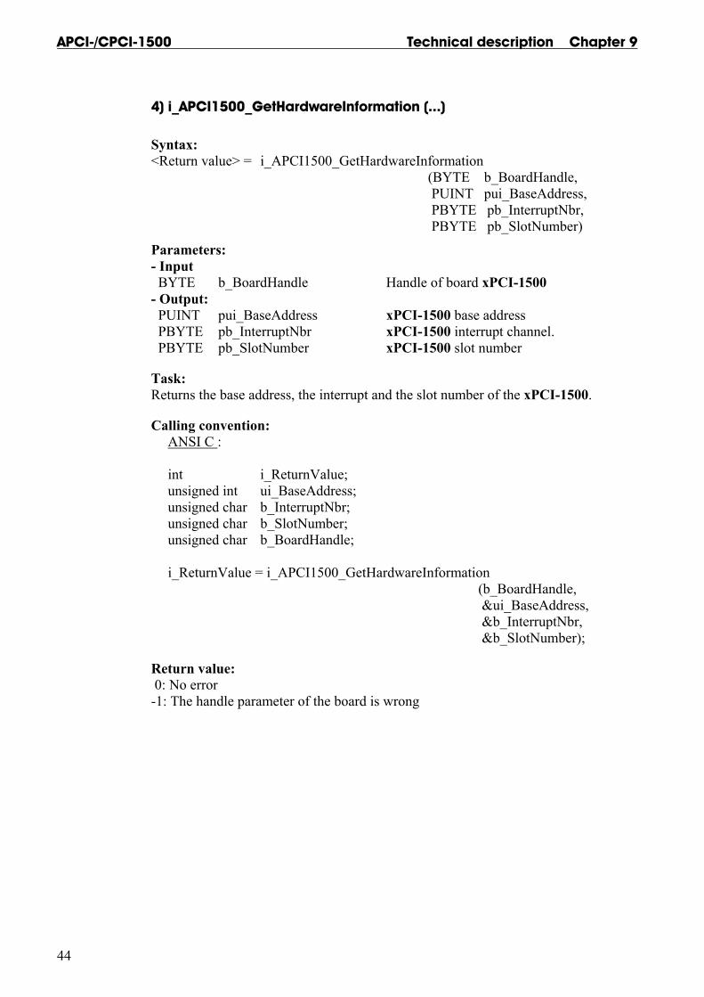
4) i_APCI1500_GetHardwareInformation (...)
Syntax: <Return value> = i_APCI1500_GetHardwareInformation (BYTE b_BoardHandle, PUINT pui_BaseAddress, PBYTE pb_InterruptNbr, PBYTE pb_SlotNumber)
Parameters: - Input BYTE b_BoardHandle Handle of board xPCI-1500 - Output: PUINT pui_BaseAddress xPCI-1500 base address PBYTE pb_InterruptNbr xPCI-1500 interrupt channel. PBYTE pb_SlotNumber xPCI-1500 slot number
Task: Returns the base address, the interrupt and the slot number of the xPCI-1500.
Calling convention: ANSI C : int i_ReturnValue; unsigned int ui_BaseAddress; unsigned char b_InterruptNbr; unsigned char b_SlotNumber; unsigned char b_BoardHandle; i_ReturnValue = i_APCI1500_GetHardwareInformation (b_BoardHandle, &ui_BaseAddress, &b_InterruptNbr, &b_SlotNumber);
Return value: 0: No error -1: The handle parameter of the board is wrong

Technical description Chapter 9 APCI-/CPCI-1500
45
Input
b_BoardHandle
Function diagram
b_BoardHandleOK ?
Yes
i_APCI1500_GetHardwareInformationEndOK
i_APCI1500_GetHardwareInformationEnd Error
No
Returns:- Base address
- interrupt number- Slot number
i_APCI1500_GetHardwareInformationBegin
Output
pui_BaseAddress pb_InterruptNumber
pb_SlotNumber
<Return value>
APCI-/CPCI-1500 Technical description Chapter 9
46
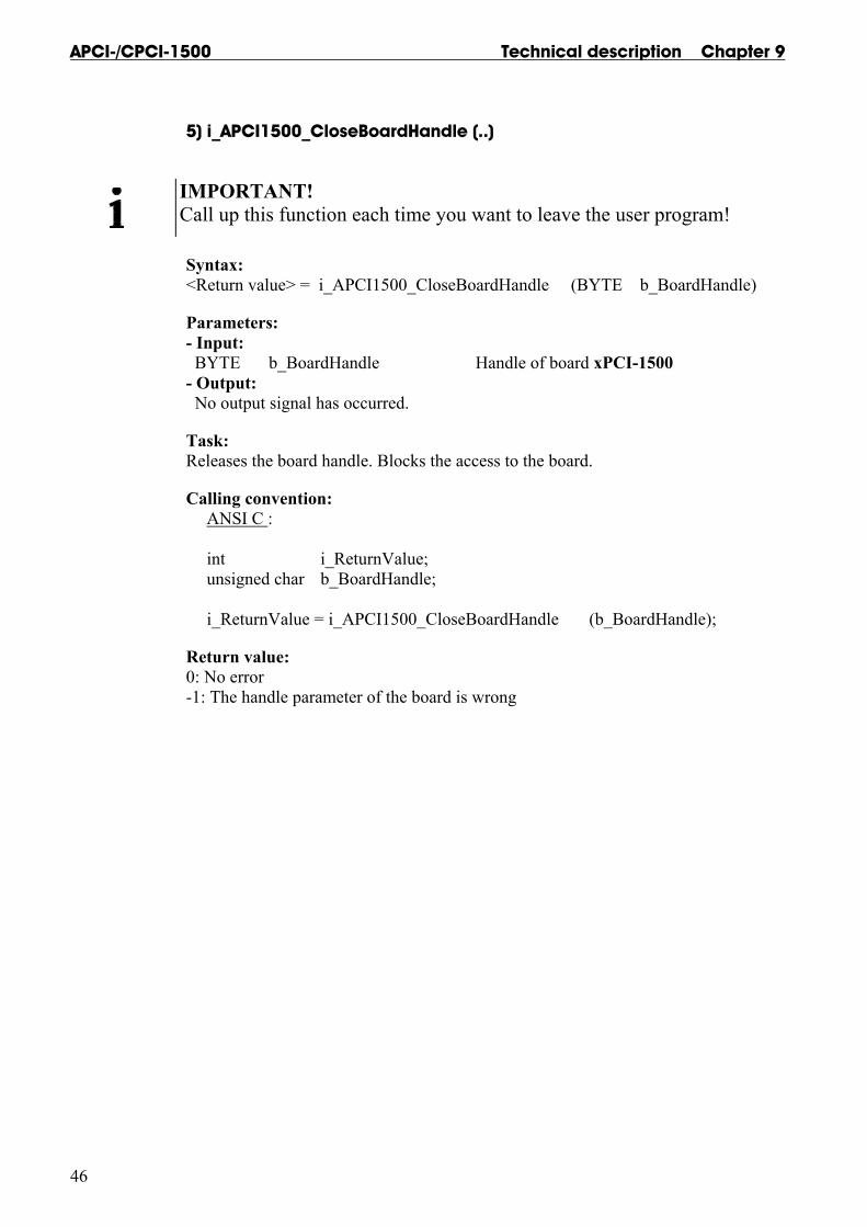
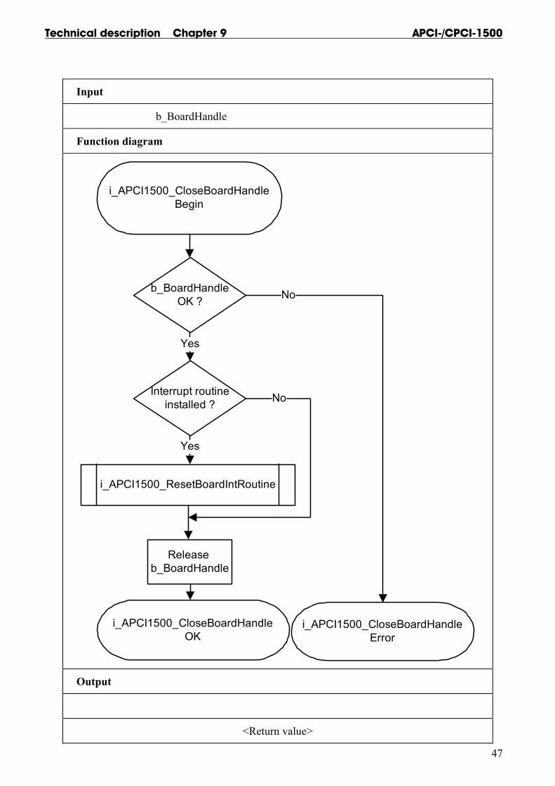
5) i_APCI1500_CloseBoardHandle (..)
IMPORTANT! Call up this function each time you want to leave the user program!
Syntax: <Return value> = i_APCI1500_CloseBoardHandle (BYTE b_BoardHandle)
Parameters: - Input: BYTE b_BoardHandle Handle of board xPCI-1500 - Output: No output signal has occurred.
Task: Releases the board handle. Blocks the access to the board.
Calling convention: ANSI C : int i_ReturnValue; unsigned char b_BoardHandle; i_ReturnValue = i_APCI1500_CloseBoardHandle (b_BoardHandle);
Return value: 0: No error -1: The handle parameter of the board is wrong
Technical description Chapter 9 APCI-/CPCI-1500
47
Input
b_BoardHandle
Function diagram
i_APCI1500_CloseBoardHandleBegin
b_BoardHandleOK ?
Interrupt routineinstalled ?
Yes
i_APCI1500_ResetBoardIntRoutine
Yes
Release b_BoardHandle
No
i_APCI1500_CloseBoardHandleOK
i_APCI1500_CloseBoardHandleError
No
Output
<Return value>

APCI-/CPCI-1500 Technical description Chapter 9
48
9.3.2 Interrupt
IMPORTANT! This function is only available for C/C++ and Pascal for DOS.
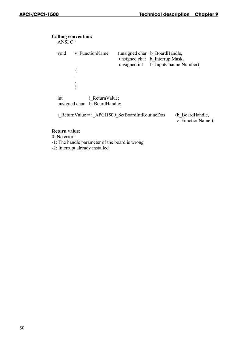
1) i_APCI1500_SetBoardIntRoutineDos (..)
Syntax: <Return value> = i_APCI1500_SetBoardIntRoutineDos (BYTE b_BoardHandle, VOID v_FunctionName (BYTE b_BoardHandle, BYTE b_InterruptMask BYTE b_InputChannelNbr))
Parameters: - Input: BYTE b_BoardHandle Handle of board xPCI-1500 VOID v_FunctionName Name of the user interrupt routine - Output: No output has occurred.
Task: This function must be called up for each xPCI-1500 on which an interrupt action is to be enabled. It installs an user interrupt function in all boards on which an interrupt is to be enabled.
First calling (first board): - the user interrupt routine is installed - interrupts are enabled.
If you operate several boards xPCI-1500 which have to react to interrupts, call up the function as often as you operate boards xPCI-1500. The variable v_FunctionName is only relevant for the first calling.
From the second call of the function (next board): - interrupts are enabled. The first board can receive IRQ.
Interrupt The user interrupt routine is called up by the system when an interrupt is generated.
An interrupt is generated when: - the counter/timer has run down - an event is generated - the watchdog has run down

Technical description Chapter 9 APCI-/CPCI-1500
49
The following errors are possible - overtemperature - short-circuit - no voltage is available
If several boards are operated and if they have to react to interrupts, the variable b_BoardHandle returns the identification number (handle) of the board which has generated the interrupt.
The user interrupt routine must have the following syntax:
VOID v_FunctionName (BYTE b_BoardHandle, BYTE b_InterruptMask, BYTE b_InputChannelNbr)
v_FunctionName Name of the user interrupt routine b_BoardHandle Handle of the xPCI-1500 which has generated the interrupt b_InterruptMask Mask of the events which have generated the interrupt. b_InputChannelNbr If an interrupt is generated with a Mask 0000 0001 and if you use the OR-PRIORITY logic, this variable gives the input number, which have generated the interrupt.
Table 9-3: Interrupt mask
Mask Meaning 0000 0001 Event 1 has occurred 0000 0010 Event 2 has occurred 0000 0100 Counter/timer 1 has run down 0000 1000 Counter/timer 2 has run down 0001 0000 Counter 3 has run down 0010 0000 Watchdog has run down 0100 0000 Voltage error 1000 0000 Short-circuit error
The user can give another name for v_FunctionName, b_BoardHandle, b_InterruptMask, b_InputChannelNbr.
APCI-/CPCI-1500 Technical description Chapter 9
50
Calling convention: ANSI C : void v_FunctionName (unsigned char b_BoardHandle, unsigned char b_InterruptMask, unsigned int b_InputChannelNumber) { . . } int i_ReturnValue; unsigned char b_BoardHandle; i_ReturnValue = i_APCI1500_SetBoardIntRoutineDos (b_BoardHandle, v_FunctionName );
Return value: 0: No error -1: The handle parameter of the board is wrong -2: Interrupt already installed
Technical description Chapter 9 APCI-/CPCI-1500
51
Input
b_BoardHandle v_FunctionName
Function diagram
i_APCI1500_SetBoardIntRoutineDosBegin
b_BoardHandleOK ?
Boardinterrupt
installed ?
Yes
Firstinterrupt
installation ?
Set API interrupt routine
i_APCI1500_SetBoardIntRoutineDosEnd
Yes
No
i_APCI1500_SetBoardIntRoutineDosError
No
Yes
No
Save oldinterrupt routine
Save v_FunktionName
Output
<Return value>

APCI-/CPCI-1500 Technical description Chapter 9
52
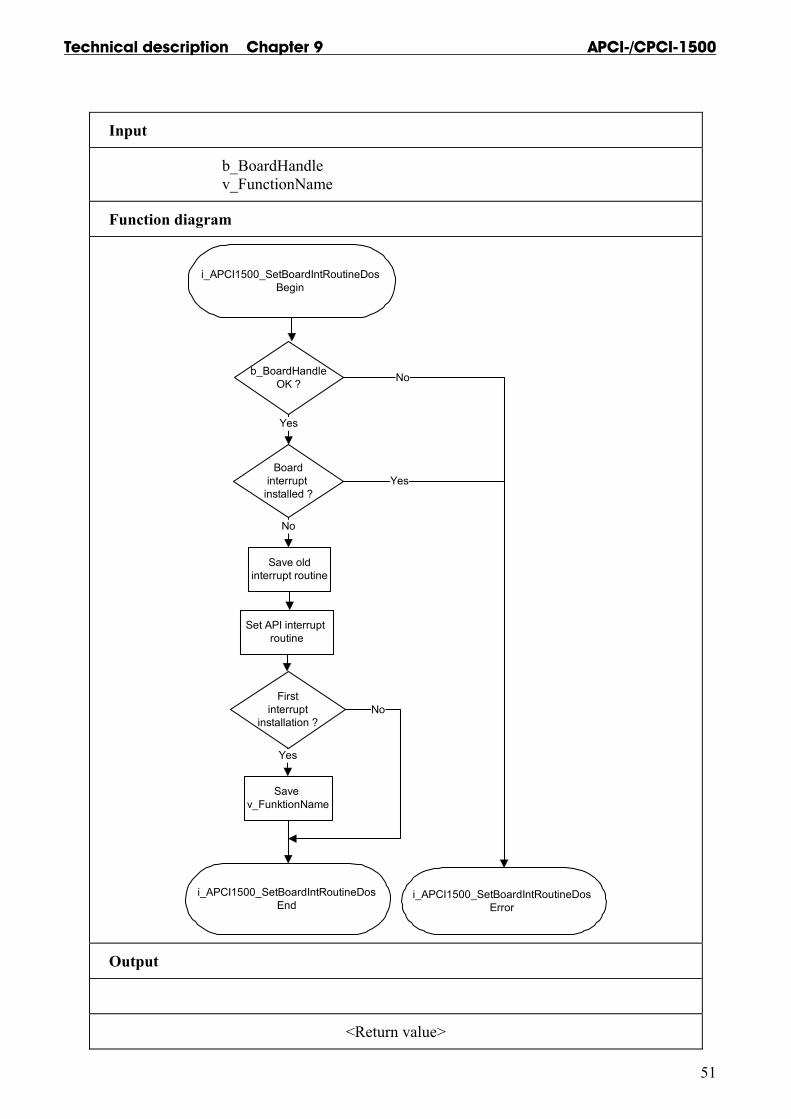
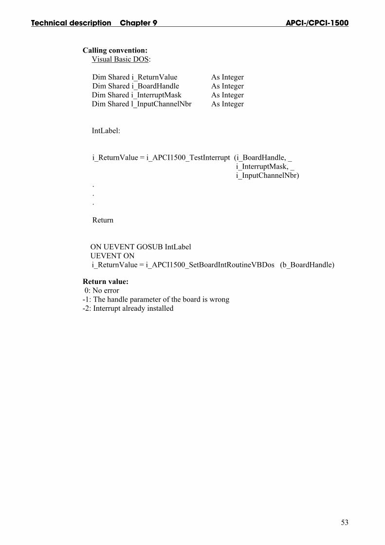
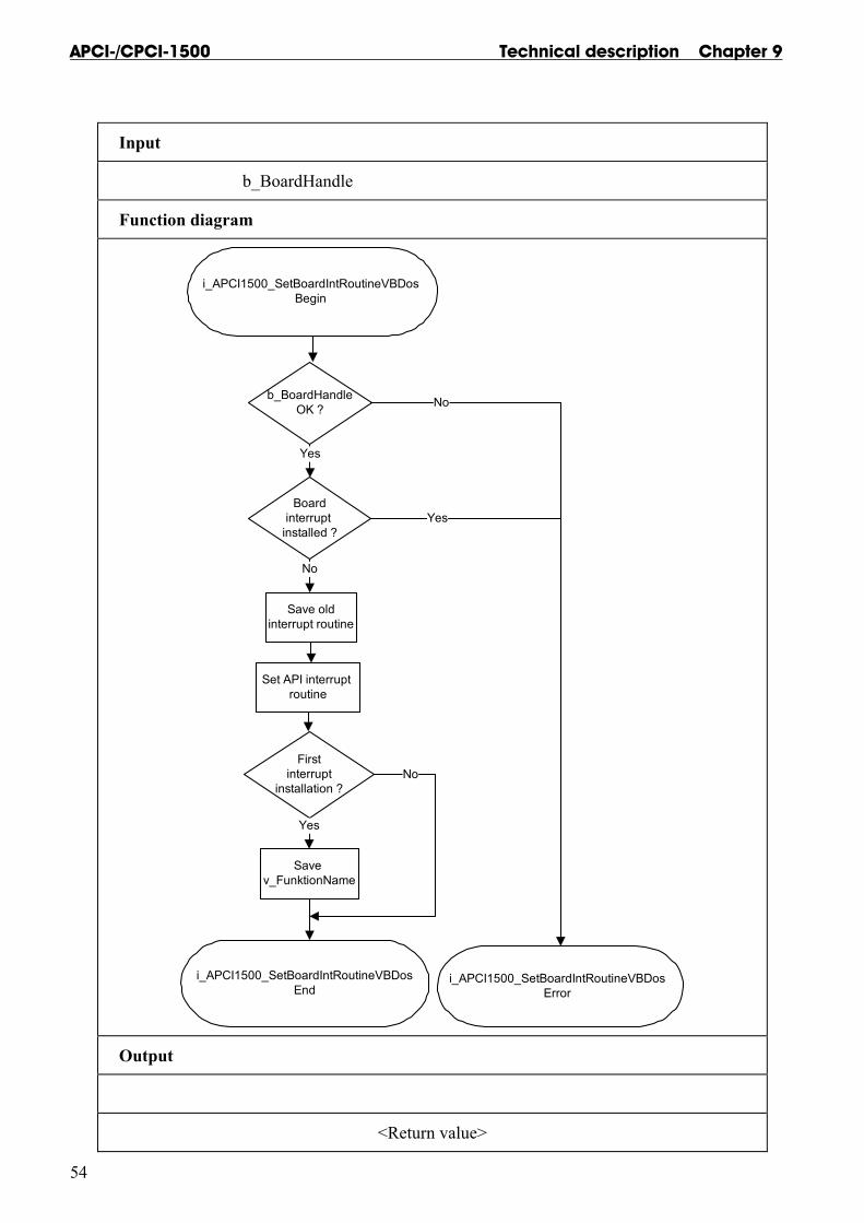
IMPORTANT! This function is only available for Visual Basic DOS.
2) i_APCI1500_SetBoardIntRoutineVBDos (..)
Syntax: <Return value> = i_APCI1500_SetBoardIntRoutineVBDos (BYTE b_BoardHandle)
Parameters: - Input: BYTE b_BoardHandle Handle of board xPCI-1500 - Output: No output signal has occurred.
Task: This function must be called up for each xPCI-1500 on which an interrupt action is to be enabled. It installs an user interrupt function in all boards on which an interrupt is to be enabled.
First calling (first board): - the user interrupt routine is installed - interrupts are enabled.
If you operate several boards xPCI-1500 which have to react to interrupts, call up the function as often as you operate boards xPCI-1500. The variable v_FunctionName is only relevant for the first calling.
Interrupt The user interrupt routine is called up by the system when an interrupt is generated.
The following errors are possible - overtemperature - short-circuit - no voltage is available
Controlling the interrupt management Please use the following functions
"ON UEVENT GOSUB xxxxxxxxx" of Visual Basic for DOS
and
"i_APCI1500_TestInterrupt"
This function tests the interrupt of the xPCI-1500. It is used for obtaining the values of b_BoardHandle , b_InterruptMask and b_InputChannelNbr.
Technical description Chapter 9 APCI-/CPCI-1500
53
Calling convention: Visual Basic DOS: Dim Shared i_ReturnValue As Integer Dim Shared i_BoardHandle As Integer Dim Shared i_InterruptMask As Integer Dim Shared l_InputChannelNbr As Integer IntLabel: i_ReturnValue = i_APCI1500_TestInterrupt (i_BoardHandle, _ i_InterruptMask, _ i_InputChannelNbr) . . . Return ON UEVENT GOSUB IntLabel UEVENT ON i_ReturnValue = i_APCI1500_SetBoardIntRoutineVBDos (b_BoardHandle)
Return value: 0: No error -1: The handle parameter of the board is wrong -2: Interrupt already installed
APCI-/CPCI-1500 Technical description Chapter 9
54
Input
b_BoardHandle
Function diagram
i_APCI1500_SetBoardIntRoutineVBDosBegin
b_BoardHandleOK ?
Boardinterrupt
installed ?
Yes
Firstinterrupt
installation ?
Set API interrupt routine
i_APCI1500_SetBoardIntRoutineVBDosEnd
Yes
No
i_APCI1500_SetBoardIntRoutineVBDosError
No
Yes
No
Save oldinterrupt routine
Save v_FunktionName
Output
<Return value>

Technical description Chapter 9 APCI-/CPCI-1500
55
IMPORTANT! This function is only available for Windows 3.1 and Windows 3.11
3) i_APCI1500_SetBoardIntRoutineWin16 (..)
Syntax: <Return value> = i_APCI1500_SetBoardIntRoutineWin16 (BYTE b_BoardHandle, VOID v_FunctionName (BYTE b_BoardHandle, BYTE b_InterruptMask, BYTE InputChannelNbr))
Parameters: - Input: BYTE b_BoardHandle Handle of board xPCI-1500 VOID v_FunctionName Name of the user interrupt routine - Output: No output signal has occurred.
Task: This function must be called up for each xPCI-1500 on which an interrupt action is to be enabled. It installs one user interrupt function in all boards on which an interrupt is to be enabled.
First calling (first board): - the user interrupt routine is installed - interrupts are enabled.
If you operate several boards xPCI-1500 which have to react to interrupts, call up the function as often as you operate boards xPCI-1500. The variable v_FunctionName is only relevant for the first calling.
From the second call of the function (next board): - interrupts are allowed.
Interrupt The user interrupt routine is called up by the system when an interrupt is generated.
An interrupt is generated when: - the counter/timer has run down - an event is generated - the watchdog has run down

APCI-/CPCI-1500 Technical description Chapter 9
56
The following errors are possible - overtemperature - short-circuit - no voltage is available
If several boards are operated and if they have to react to interrupts, the variable b_BoardHandle returns the identification number (handle) of the board which has generated the interrupt.
The user interrupt routine must have the following syntax:
VOID v_FunctionName (BYTE b_BoardHandle, BYTE b_InterruptMask, BYTE b_InputChannelNbr)
v_FunctionName Name of the user interrupt routine b_BoardHandle Handle of the xPCI-1500 which has generated the interrupt b_InterruptMask Mask of the events which have generated the interrupt. b_InputChannelNbr If an interrupt is generated with a Mask 0000 0001 and if you use the OR-PRIORITY logic, this variable gives the input number, which have generated the interrupt.
Mask Meaning 0000 0001 Event 1 has occurred 0000 0010 Event 2 has occurred 0000 0100 Counter/timer 1 has run down 0000 1000 Counter/timer 2 has run down 0001 0000 Counter 3 has run down 0010 0000 Watchdog has run down 0100 0000 Voltage error 1000 0000 Short-circuit error
The user can give another name for v_FunctionName, b_BoardHandle, b_InterruptMask, and b_InputChannelNbr.
Technical description Chapter 9 APCI-/CPCI-1500
57
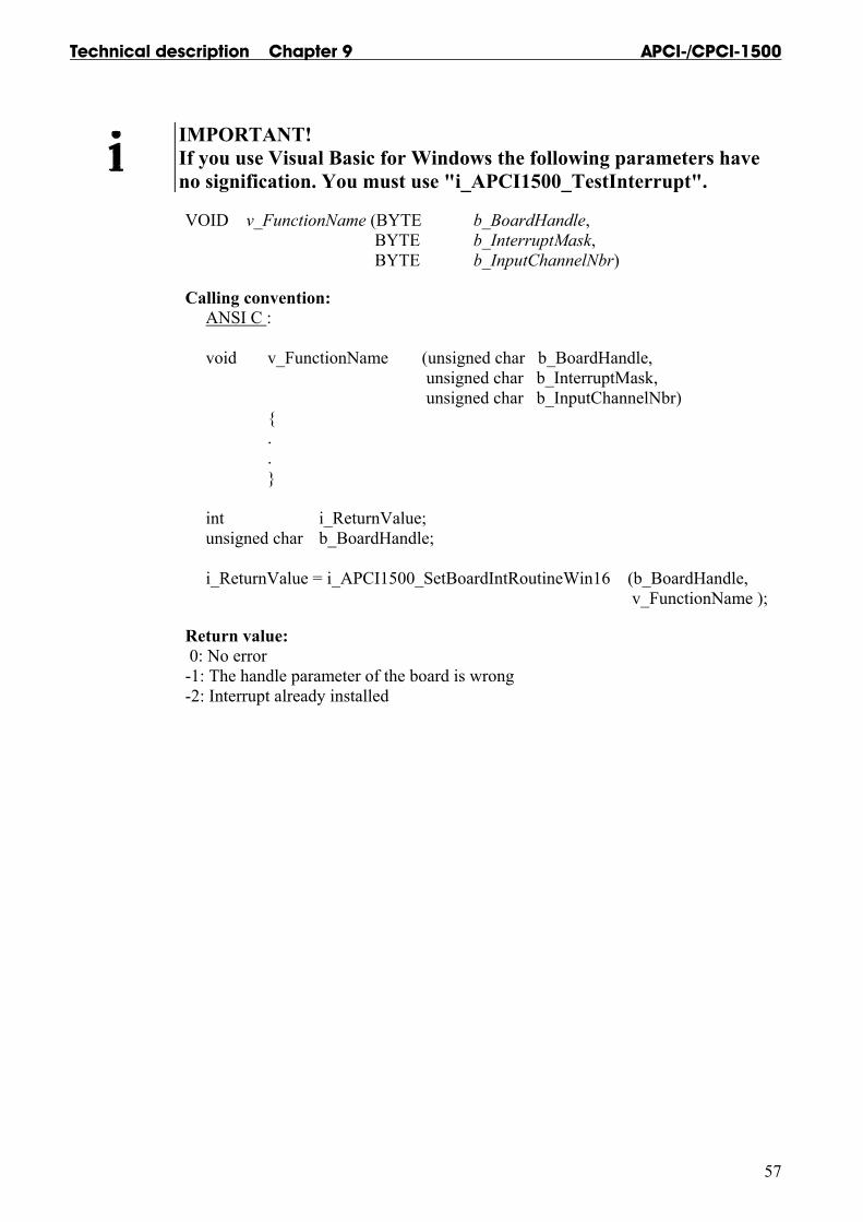
IMPORTANT! If you use Visual Basic for Windows the following parameters have no signification. You must use "i_APCI1500_TestInterrupt".
VOID v_FunctionName (BYTE b_BoardHandle, BYTE b_InterruptMask, BYTE b_InputChannelNbr)
Calling convention: ANSI C : void v_FunctionName (unsigned char b_BoardHandle, unsigned char b_InterruptMask, unsigned char b_InputChannelNbr) { . . } int i_ReturnValue; unsigned char b_BoardHandle; i_ReturnValue = i_APCI1500_SetBoardIntRoutineWin16 (b_BoardHandle, v_FunctionName );
Return value: 0: No error -1: The handle parameter of the board is wrong -2: Interrupt already installed
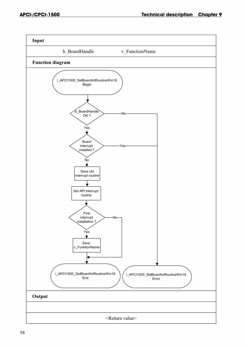
APCI-/CPCI-1500 Technical description Chapter 9
58
Input
b_BoardHandle v_FunctionName
Function diagram
i_APCI1500_SetBoardIntRoutineWin16Begin
b_BoardHandleOK ?
Boardinterrupt
installed ?
Yes
Firstinterrupt
installation ?
Set API interrupt routine
i_APCI1500_SetBoardIntRoutineWin16End
Yes
No
i_APCI1500_SetBoardIntRoutineWin16Error
No
Yes
No
Save oldinterrupt routine
Save v_FunktionName
Output
<Return value>
Technical description Chapter 9 APCI-/CPCI-1500
59
IMPORTANT! This function is only available for Windows NT and Windows 2000/9x.
4) i_APCI1500_SetBoardIntRoutineWin32 (..)
Syntax: <Return value> = i_APCI1500_SetBoardIntRoutineWin32 (BYTE b_BoardHandle, BYTE b_UserCallingMode, ULONG ul_UserSharedMemorySize, VOID ** ppv_UserSharedMemory, VOID v_FunctionName (BYTE b_BoardHandle, BYTE b_InterruptMask, BYTE b_InputChannelNbr, BYTE b_UserCallingMode, VOID * pv_UserSharedMemory))
Parameters: - Input: BYTE b_BoardHandle Handle of board xPCI-1500 BYTE b_UserCallingMode APCI1500_SYNCHRONOUS_MODE: The user routine is directly called by the driver interrupt routine. APCI1500_ASYNCHRONOUS_MODE: The user routine is called by the driver interrupt thread. VOID v_FunctionName Name of the user interrupt routine ULONG ul_UserSharedMemorySize Determines the size in bytes of the user shared memory. Only used if you have selected APCI1500_SYNCHRONOUS_MODE - Output: VOID ** ppv_UserSharedMemory User shared memory address Only used if you have selected APCI1500_SYNCHRONOUS_MODE.

APCI-/CPCI-1500 Technical description Chapter 9
60
Task:
Windows 32-bit information For Windows NT and Windows 2000/9x, 4 running rings (ring 0 to ring 3) are available.
- The user application operates in ring 3. This ring gives no access to hardware. - VXD and SYS driver operate in ring 0 and give access to hardware. - Ring 0 has no direct access to global variable from ring 3. It has to use a shared memory. - Ring 0 and ring 3 have a pointer that points on this shared memory. These 2 pointers are not configured under the same address.
This function must be called up for each xPCI-1500 on which an interrupt is to be enabled. It installs one user interrupt function in all boards on which an interrupt is to be enabled.
First calling (first board): - the user interrupt routine is installed - interrupts are enabled - user shared memory is allocated if APCI1500_SYNCHROUNOUS_MODE ahs been selected.
If you operate several boards xPCI-1500 which have to react to interrupts, call up the function as often as you operate boards xPCI-1500. The variable v_FunctionName is only relevant for the first calling.
From the second call of the function (next board): - interrupts are allowed.
Interrupt The user interrupt routine is called up by the system when an interrupt is generated.
An interrupt is generated when: - the counter/timer has run down - an event is generated - the watchdog has run down
The following errors are possible - overtemperature - short-circuit - no voltage is available
If several boards are operated and if they have to react to interrupts, the variable b_BoardHandle returns the identification number (handle) of the board which has generated the interrupt.

Technical description Chapter 9 APCI-/CPCI-1500
61
User interrupt routine can be called :
- directly by the driver interrupt routine (Synchronous mode). The code of the user interrupt routine directly operates in ring 0. - by the driver interrupt thread (Asynchronous mode). An event is generated and the interrupt thread calls up the user interrupt routine. The code of the user interrupt routine operates in ring 3. The driver interrupt thread have the highest priority (31) from system.
Driver interrupt routine
User interrupt routine
Driver interrupt routine
Driver interrupt thread
User interrupt routine
Event
Synchronous mode Asynchronous mode
SYNCHRONOUS-MODE
ADVANTAGE The code of the user interrupt routine is directly called by driver interrupt routine (ring 0). The time between interrupt and the user interrupt routine is reduced.
The user cannot debug the user interrupt routine.
The user routine cannot call Windows API functions.
RESTRICTION The user routine cannot call functions which give access to global variables. The user can still use a shared memory.
The user routine can only call xPCI-1500 driver functions with the following extension "i_APCI1500_KRNL_XXXX"
This mode is not available for Visual Basic

APCI-/CPCI-1500 Technical description Chapter 9
62
ASYNCHRONOUS-MODE
The user can debug the user interrupt routine provided he has not programmed in Visual Basic 5
ADVANTAGE The user routine can call Windows API functions.
The user routine can call functions which give access to global variables.
The user routine can call all xPCI-1500 driver functions with the following extension: "i_APCI1500_XXXX"
RESTRICTION The code of the user interrupt routine is called by driver interrupt thread routine (ring 3). The time between interrupt and the user interrupt routine is increased.
Shared memory If you have selected the APCI1500_SYNCHRONOUS_MODE you cannot have access to global variables. But you have the possibility to create a shared memory (ppv_UserSharedMemory). The user shared memory can have all predefined compiler types or user define types. The variable ul_UserSharedMemorySize indicates the size in bytes of the selected user type. A pointer of the variable ppv_UserSharedMemory is given to the user interrupt routine with the variable pv_UserSharedMemory .This is not possible for Visual Basic.
The user interrupt routine must have the following syntax:
VOID v_FunctionName (BYTE b_BoardHandle, BYTE b_InterruptMask, BYTE b_InputChannelNbr, BYTE b_UserCallingMode, VOID * pv_UserSharedMemory)
v_FunctionName Name of the user interrupt routine b_BoardHandle Handle of the xPCI-1500 which has generated the interrupt b_InterruptMask Mask of the events which have generated the interrupt. b_InputChannelNbr If an interrupt is generated with a Mask 0000 0001 and if you use the OR-PRIORITY logic, this variable gives the input number, which has generated the interrupt. b_UserCallingMode APCI1500_SYNCHRONOUS_MODE: The user routine is directly called by the driver interrupt routine. APCI1500_ASYNCHRONOUS_MODE: The user routine is called by driver the interrupt thread pv_UserSharedMemory Pointer of the user shared memory.
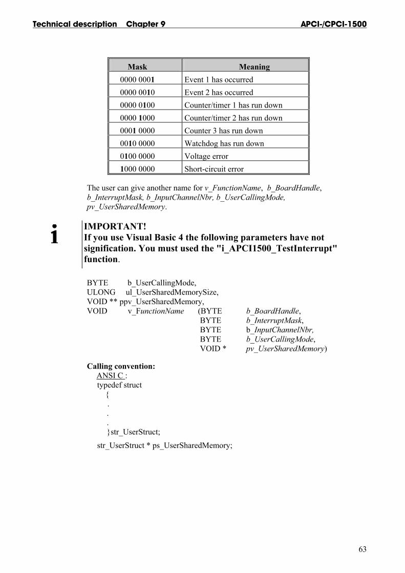
Technical description Chapter 9 APCI-/CPCI-1500
63
Mask Meaning 0000 0001 Event 1 has occurred 0000 0010 Event 2 has occurred 0000 0100 Counter/timer 1 has run down 0000 1000 Counter/timer 2 has run down 0001 0000 Counter 3 has run down 0010 0000 Watchdog has run down 0100 0000 Voltage error 1000 0000 Short-circuit error
The user can give another name for v_FunctionName, b_BoardHandle, b_InterruptMask, b_InputChannelNbr, b_UserCallingMode, pv_UserSharedMemory.
IMPORTANT! If you use Visual Basic 4 the following parameters have not signification. You must used the "i_APCI1500_TestInterrupt" function. BYTE b_UserCallingMode, ULONG ul_UserSharedMemorySize, VOID ** ppv_UserSharedMemory, VOID v_FunctionName (BYTE b_BoardHandle, BYTE b_InterruptMask, BYTE b_InputChannelNbr, BYTE b_UserCallingMode, VOID * pv_UserSharedMemory)
Calling convention: ANSI C : typedef struct { . . . }str_UserStruct;
str_UserStruct * ps_UserSharedMemory;

APCI-/CPCI-1500 Technical description Chapter 9
64
void v_FunctionName (unsigned char b_BoardHandle, unsigned char b_InterruptMask, unsigned char b_InputChannelNbr, unsigned char b_UserCallingMode, void * pv_UserSharedMemory) { str_UserStruct * ps_InterruptSharedMemory;
ps_InterruptSharedMemory = (str_UserStruct *) pv_UserSharedMemory; . . }
int i_ReturnValue; unsigned char b_BoardHandle;
i_ReturnValue = i_APCI1500_SetBoardIntRoutineWin32 (b_BoardHandle, APCI1500_SYNCHRONOUS_MODE, sizeof (str_UserStruct), (void **) &ps_UserSharedMemory, v_FunctionName); Visual Basic 5:
Sub v_FunctionName (ByVal i_BoardHandle As Integer, ByVal i _InterruptMask As Integer, ByVal i _InputChannelNbr As Integer, ByVal b_UserCallingMode As Integer, ByVal l_UserSharedMemory As Long) End Sub
Dim i_ReturnValue As Integer Dim i_BoardHandle As Integer
i_ReturnValue = i_APCI1500_SetBoardIntRoutineWin32 (i_BoardHandle, APCI1500_ASYNCHRONOUS_MODE, 0, 0, AddressOf v_FunctionName)
Return value: 0: No error -1: The handle parameter of the board is wrong -2: Interrupt already installed -3: Calling mode selection of the user interrupt routine is wrong -4: No memory available for the user shared memory

Technical description Chapter 9 APCI-/CPCI-1500
65
Input
b_BoardHandle b_UserCallingMode
ul_UserSharedMemorySize v_FunctionName
Function diagram
i_APCI1500_SetBoardintRoutineWin32Begin
b_BoardHandleOK ?
Boardinterrupt installed ?
Yes
First interruptinstallation ?
Set API interrupt routine
i_APCI1500_SetBoardIntRoutineWin32End
Yes
No
No
Yes
No
Save v_FunktionName
Asynchronousmode ?
Set API interrupt thread
Create user shared memory
User sharedmemory size > 0 ?
No
Yes
No
Yes
i_APCI1500_SetBoardintRoutineWin32Error
Output
ppv_UserSharedMemory
<Return value>

APCI-/CPCI-1500 Technical description Chapter 9
66
5) i_APCI1500_TestInterrupt (..)
Syntax: <Return value> = i_APCI1500_TestInterrupt (PBYTE pb_BoardHandle, PBYTE pb_InterruptMask, PBYTE pb_ChannelNbr)
Parameters: - Input: No input signal is to occur. - Output: PBYTE pb_BoardHandle Handle of the board PCI-1500 which has generated the interrupt, PBYTE pb_InterruptMask Error mask of the event which has generated the interrupt. Several errors can occur simultaneously. PBYTE pb_ChannelNbr If an interrupt occurs with the mask 0000 0001 and if you use the OR PRIORITY logic this variable returns the input number which has generated the event.
Mask Meaning 0000 0001 Event 1 has occurred 0000 0010 Event 2 has occurred 0000 0100 Counter/timer 1 has run down 0000 1000 Counter/timer 2 has run down 0001 0000 Counter 3 has run down 0010 0000 Watchdog has run down 0100 0000 Voltage error 1000 0000 Short-circuit error
Task: Checks if a board xPCI-1500 has generated an interrupt. If yes, the function returns the board handle and the interrupt source.
IMPORTANT! This function is only in Visual Basic Dos and Windows available.
Calling convention: ANSI C : unsigned char b_BoardHandle; unsigned char b_InterruptMask; unsigned char b_ChannelNbr; int i_Irq; Irq = i_APCI1500_TestInterrupt (&b_BoardHandle, & b_InterruptMask, & b_ChannelNbr);

Technical description Chapter 9 APCI-/CPCI-1500
67
Return value: -1: No interrupt > 0: IRQ number
Input
Function diagram
i_APCI1500_TestInterruptBegin
Interrupt occurred?
i_APCI1500_TestInterruptOK
i_APCI1500_TestInterruptError
No
Yes
- Get pb_BoardHandle - Get pb_InterruptMask - Get pb_ChannelNbr
Output
b_BoardHandle b_InterruptMask
pb_ChannelNbr
<Return value>
APCI-/CPCI-1500 Technical description Chapter 9
68
6) i_APCI1500_ResetBoardIntRoutine (..)
Syntax: <Return value> = i_APCI1500_ResetBoardIntRoutine (BYTE b_BoardHandle)
Parameters: - Input: BYTE b_BoardHandle Handle of board xPCI-1500 - Output: No output signal has occurred.
Task: Stops the interrupt management of board xPCI-1500. Deinstalls the interrupt routine if the management of interrupts of all xPCI-1500 is stopped.
Calling convention: ANSI C : unsigned char b_BoardHandle; Irq = i_APCI1500_ResetBoardIntRoutine (b_BoardHandle);
Return value: 0: No error -1: Handle parameter of the board is wrong -2: Interrupt routine is not installed

Technical description Chapter 9 APCI-/CPCI-1500
69
Input
b_BoardHandle
Function diagram
i_APCI1500_ResetBoardIntRoutineBegin
b_BoardHandleOK ?
Board interrupt installed?
Restore old interrupt and disable
APCI-1500 interrupt
i_APCI1500_ResetBoardIntRoutineOK
i_APCI1500_ResetBoardIntRoutineError
No
No
Yes
Yes
Output
<Return value>

APCI-/CPCI-1500 Technical description Chapter 9
70
9.3.3 Kernel functions
1) i_APCI1500_KRNL_Read16DigitalInput (...)
Syntax: <Return value> = i_APCI1500_KRNL_Read16DigitalInput (UINT ui_BaseAddress, PLONG pl_InputValue)
Parameters: - Input: UINT ui_BaseAddress xPCI-1500 base address - Output: PLONG pl_InputValue State of the digital input channels of both ports (0 to 65535)
Task: Indicates the state of both ports. Reads the 16 input channels at once.
Example:
pl_InputValue = 5555 Hex
A voltage is present on the input channels 1, 3, 5, 7, 9, 11, 13, 15 . A voltage is not present on the input channels 2, 4, 6, 8, 10, 12, 14, 16. Return value: 0: No error

Technical description Chapter 9 APCI-/CPCI-1500
71
2) v_APCI1500_KRNL_Set16DigitalOutputOn (...)
Syntax: <Return value> = v_APCI1500_KRNL_Set16DigitalOutputOn (UINT ui_BaseAddress, LONG l_Value)
Parameters: - Input: UINT ui_BaseAddress xPCI-1500 base address LONG l_Value Output value (0 to 65535) - Output: No output signal has occurred.
Task: Sets one or several output channels of board xPCI-1500
Example: l_Value = 5555 Hex
The output channels 1, 3, 5, 7, 9, 11, 13, 15 are set. The output channels 2, 4, 6, 8, 10, 12, 14, 16 are reset.
Return value: 0: No error

APCI-/CPCI-1500 Technical description Chapter 9
72
9.3.4 Digital input channel
1) i_APCI1500_Read1DigitalInput (...)
Syntax : <Return value> = i_APCI1500_Read1DigitalInput (BYTE b_BoardHandle, BYTE b_Channel, PBYTE pb_ChannelValue) Parameters: BYTE b_BoardHandle Handle of board xPCI-1500 BYTE b_Channel The number of the input channel to be read (1 to 16) PBYTE pb_ChannelValue State of the digital input channel: 0 -> low 1 -> high
Task: Indicates the state of an input channel. The variable b_Channel passes the input channel to be read (1 to 16). A value is returned with the variable pb_ChannelValue : 0 (low) or 1 (high).
Return value: 0: No error -1: The handle parameter of the board is wrong -2: The input number is not between 1 and 16
2) i_APCI1500_Read8DigitalInput (...)
Syntax: <Return value> = i_APCI1500_Read8DigitalInput (BYTE b_BoardHandle, BYTE b_Port, PBYTE pb_PortValue) Parameters: BYTE b_BoardHandle Handle of the xPCI-1500 BYTE b_Port Number of the input port you want to read (1 or 2) PBYTE pb_PortValue State of the digital input port (0 to 255)
Task: Indicates the state of a port. The variable b_Port passes the port to be read (1 or 2). A value is returned with the variable pb_PortValue .
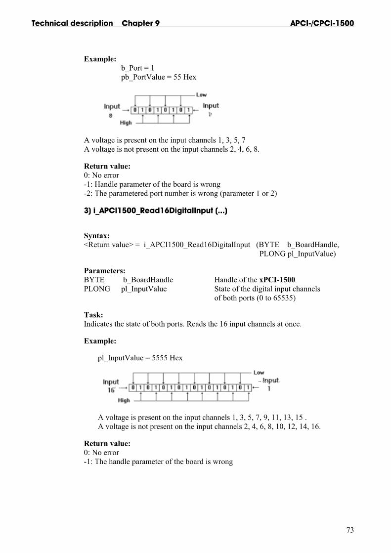
Technical description Chapter 9 APCI-/CPCI-1500
73
Example: b_Port = 1 pb_PortValue = 55 Hex
A voltage is present on the input channels 1, 3, 5, 7 A voltage is not present on the input channels 2, 4, 6, 8.
Return value: 0: No error -1: Handle parameter of the board is wrong -2: The parametered port number is wrong (parameter 1 or 2)
3) i_APCI1500_Read16DigitalInput (...)
Syntax: <Return value> = i_APCI1500_Read16DigitalInput (BYTE b_BoardHandle, PLONG pl_InputValue)
Parameters: BYTE b_BoardHandle Handle of the xPCI-1500 PLONG pl_InputValue State of the digital input channels of both ports (0 to 65535)
Task: Indicates the state of both ports. Reads the 16 input channels at once.
Example:
pl_InputValue = 5555 Hex
A voltage is present on the input channels 1, 3, 5, 7, 9, 11, 13, 15 . A voltage is not present on the input channels 2, 4, 6, 8, 10, 12, 14, 16.
Return value: 0: No error -1: The handle parameter of the board is wrong

APCI-/CPCI-1500 Technical description Chapter 9
74
9.3.5 Digital input channel - events
1) i_APCI1500_SetInputEventMask (...)
Syntax: <Return value> = i_APCI1500_SetInputEventMask (BYTE b_BoardHandle, BYTE b_PortNbr, BYTE b_Logik, PCHAR pc_EventMask)
Parameters: BYTE b_BoardHandle Handle of board xPCI-1500 BYTE b_Port Number of the input port to be masked (1 or 2) BYTE b_Logik Event logic Three possibilities for the first port: APCI1500_AND: This logic connects the input channels with an AND logic. APCI1500_OR: This logic connects the input channels with an OR logic. APCI1500_OR_PRIORITY: This logic connects the input channels with a priority OR logic. Input 1 has the highest priority Input 8 has the lowest priority One possibility for the second port: APCI1500_OR: This logic connects the input channels with a OR logic. PCHAR pc_EventMask This 8-digit character string (port 1) and 6-digit character string (port 2) defines the mask of the event. Each digit indicates the state of the input channel. The state is identified by one of the following characters: "X": This input channel is not used for event "0": The input channel must be on "0" "1": The input channel must be on "1" "2": The input channel reacts to a falling edge "3": The input channel reacts to a rising edge "4": The input channel reacts to both edges Port 1: from the left to the right, the first digit of the character string is input 8 and the last digit is input 1. Port 2: from the left to the right, the first digit of the character string is input 14 and the last digit is input 9.
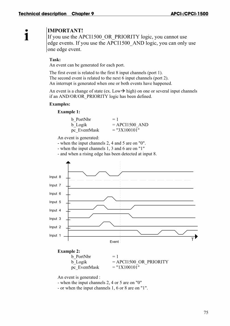
Technical description Chapter 9 APCI-/CPCI-1500
75
IMPORTANT! If you use the APCI1500_OR_PRIORITY logic, you cannot use edge events. If you use the APCI1500_AND logic, you can only use one edge event.
Task: An event can be generated for each port.
The first event is related to the first 8 input channels (port 1). The second event is related to the next 6 input channels (port 2). An interrupt is generated when one or both events have happened.
An event is a change of state (ex. Low high) on one or several input channels if an AND/OR/OR_PRIORITY logic has been defined.
Examples:
Example 1: b_PortNbr = 1
b_Logik = APCI1500_AND pc_EventMask = "3X100101"
An event is generated: - when the input channels 2, 4 and 5 are on "0". - when the input channels 1, 3 and 6 are on "1" - and when a rising edge has been detected at input 8.
T
Input 8
Input 7
Input 6
Input 5
Input 4
Input 3
Input 2
Input 1
Event
Example 2: b_PortNbr = 1 b_Logik = APCI1500_OR_PRIORITY pc_EventMask = "1X100101"
An event is generated : - when the input channels 2, 4 or 5 are on "0" - or when the input channels 1, 6 or 8 are on "1".

APCI-/CPCI-1500 Technical description Chapter 9
76
T
Input 8
Input 7
Input 6
Input 5
Input 4
Input 3
Input 2
Inputl 1
1st eventon input 1
2nd event
3rd event
4th event
on input 8
5th event
on input 2
6th event
on input 4
7th event
8th event
9th event
10th eventon input 1
on input 3
on input 5
on input 8
on input 6
on input 1
Return value: 0: No error -1: The handle parameter of the board is wrong -2: The parametered port number is wrong (parameter 1 or 2) -3: Error with the logic parameter . b_Logik has not the expected value -4: Error with the mask parameter . pc_EventMask has not the expected value -5: Interrupt routine not installed -6: More than 1 edge event has been declared for an AND logic -7: The OR PRIORITY logic does not support any edge event
Technical description Chapter 9 APCI-/CPCI-1500
77
2) i_APCI1500_StartInputEvent (...)
Syntax : <Return value> = i_APCI1500_StartInputEvent (BYTE b_BoardHandle, BYTE b_PortNbr) Parameters: BYTE b_BoardHandle Handle of the xPCI-1500 BYTE b_Port Number of the input port (1 or 2)
Task: As soon as the function is called, it is possible to process an event on one port. First mask the input channels with the following function
i_APCI1500_SetInputEventMask .
Return value: 0: No error -1: Handle parameter of the board is wrong -2: The parametered port number is wrong -3: Event has not been initialised with the function "i_APCI1500_SetInputEvent".
3) i_APCI1500_StopInputEvent (...)
Syntax: <Return value> = i_APCI1500_StopInputEvent (BYTE b_BoardHandle, BYTE b_PortNbr) Parameters: BYTE b_BoardHandle Handle of the xPCI-1500 BYTE b_Port Number of the input port (1 or 2)
Task: As soon as the function is called, it is not possible to process an event on one port.
Return value: 0: No error -1: Handle parameter of the board is wrong -2: The parametered port number is wrong -3: Event has not been initialised with the function "i_APCI1500_SetInputEvent"
APCI-/CPCI-1500 Technical description Chapter 9
78
9.3.6 Digital output channel
1) i_APCI1500_SetOutputMemoryOn (...)
Syntax: <Return value> = i_APCI1500_SetOutputMemoryOn (BYTE b_BoardHandle)
Parameters: BYTE b_BoardHandle Handle of the xPCI-1500
Task: Activates the digital output memory. After calling this function, the output channels you have previously activated with the functions "i_APCI1500_SetXDigitalOutputOn" are not reset. You can reset them with the function "i_APCI1500_SetXDigitalOutputOff".
Return value: 0: No error -1: Handle parameter of the board is wrong
2) i_APCI1500_SetOutputMemoryOff (...)
Syntax: <Return value> = i_APCI1500_SetOutputMemoryOff (BYTE b_BoardHandle)
Parameters: BYTE b_BoardHandle Handle of the xPCI-1500
Task: Deactivates the digital output memory.
Return value: 0: No error -1: Handle parameter of the board is wrong
3) i_APCI1500_Set1DigitalOutputOn (...)
Syntax: <Return value> = i_APCI1500_Set1DigitalOutputOn (BYTE b_BoardHandle, BYTE b_Channel)
Parameters: BYTE b_BoardHandle Handle of the xPCI-1500 BYTE b_Channel Number of the output channel you want to set (1 to 16)
Technical description Chapter 9 APCI-/CPCI-1500
79
Task: Sets the output channel which has been passed with b_Channel. Setting an output channel means setting an output channel on high.
Switching on the digital output memory (ON) see function "i_APCI1500_SetOutputMemoryOn (...) b_Channel= 1
The output channel 1 is set. The others output channels hold their state.
Switching off the digital output memory (OFF) see function "i_APCI1500_SetOutputMemoryOff (...) b_Channel= 1
The output channel 1 is set. The others output channels are reset.
If you have switched off the digital output memory (OFF), all the others input channels are set to "0".
Return value: 0: No error -1: Handle parameter of the board is wrong -2: Input number is not between 1 and 16
4) i_APCI1500_Set1DigitalOutputOff (...)
Syntax : <Return value> = i_APCI1500_Set1DigitalOutputOff (BYTE b_BoardHandle, BYTE b_Channel) Parameters: BYTE b_BoardHandle Handle of the xPCI-1500 BYTE b_Channel Number of the output channel you want to reset (1 to 16)
Task: Resets the output channel you have passed with b_Channel. Resetting an output channel means setting to low.
IMPORTANT! You can use this function only if the digital output memory is ON. See function i_APCI1500_SetOutputMemoryOn (..).
Return value: 0: No error -1: The handle parameter of the board is wrong -2: The input number is not between 1 and 16 -3: Digital output memory OFF. First use the function "i_APCI1500_SetOutputMemoryOn"
APCI-/CPCI-1500 Technical description Chapter 9
80
5) i_APCI1500_Set8DigitalOutputOn (...)
Syntax: <Return value> = i_APCI1500_Set8DigitalOutputOn (BYTE b_BoardHandle, BYTE b_Port, BYTE b_Value) Parameters: BYTE b_BoardHandle Handle of the board xPCI-1500 BYTE b_Port Number of the output port (1 or 2) BYTE b_Value Output value (0 to 255)
Task: Sets one or several output channels of a port. Setting an output channel means setting to high. If you have switched off the digital output memory (OFF), the input channels are set to "0".
Example:
Switching on the digital output memory (ON) see function "i_APCI1500_SetOutputMemoryOn (...)
b_Port = 1 b_Value = 55 Hex
The output channels 1, 3, 5, 7 are set. The other output channels hold their state.
Switching off the digital output memory (OFF) see function "i_APCI1500_SetOutputMemoryOff (...)
b_Port = 1 b_Value = 55 Hex
The output channels 1, 3, 5, 7 are set. The other output channels are reset.
Return value: 0: No error -1: The handle parameter of the board is wrong -2: The port number is not 1 or 2
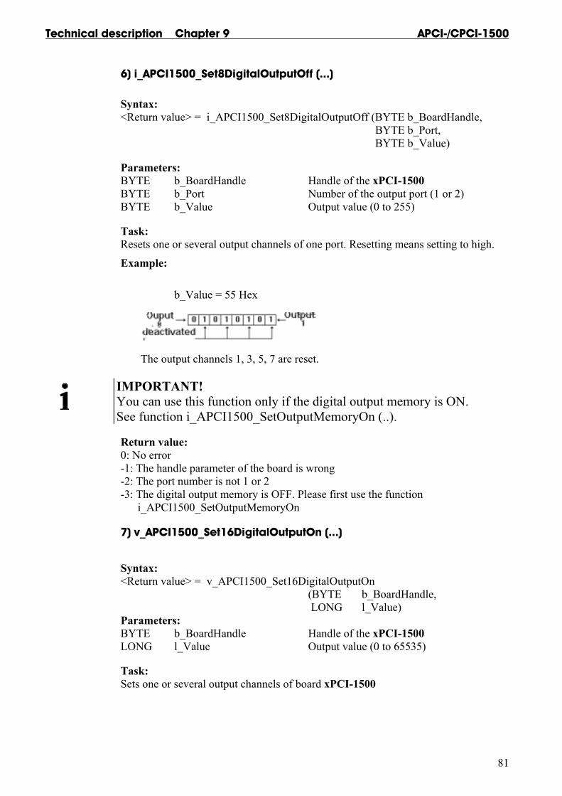
Technical description Chapter 9 APCI-/CPCI-1500
81
6) i_APCI1500_Set8DigitalOutputOff (...)
Syntax: <Return value> = i_APCI1500_Set8DigitalOutputOff (BYTE b_BoardHandle, BYTE b_Port, BYTE b_Value)
Parameters: BYTE b_BoardHandle Handle of the xPCI-1500 BYTE b_Port Number of the output port (1 or 2) BYTE b_Value Output value (0 to 255)
Task: Resets one or several output channels of one port. Resetting means setting to high.
Example: b_Value = 55 Hex
The output channels 1, 3, 5, 7 are reset.
IMPORTANT! You can use this function only if the digital output memory is ON. See function i_APCI1500_SetOutputMemoryOn (..).
Return value: 0: No error -1: The handle parameter of the board is wrong -2: The port number is not 1 or 2 -3: The digital output memory is OFF. Please first use the function i_APCI1500_SetOutputMemoryOn
7) v_APCI1500_Set16DigitalOutputOn (...)
Syntax: <Return value> = v_APCI1500_Set16DigitalOutputOn (BYTE b_BoardHandle, LONG l_Value) Parameters: BYTE b_BoardHandle Handle of the xPCI-1500 LONG l_Value Output value (0 to 65535)
Task: Sets one or several output channels of board xPCI-1500

APCI-/CPCI-1500 Technical description Chapter 9
82
Example:
Switching on the digital output memory (ON) see function "i_APCI1500_SetOutputMemoryOn (...)
l_Value = 5555 Hex
The output channels 1, 3, 5, 7, 9, 11, 13, 15 are set. The other output channels hold their state.
Switching off the digital output memory (OFF) see function "i_APCI1500_SetOutputMemoryOff (...)
l_Value = 5555 Hex
Outputs 1, 3, 5, 7, 9, 11, 13, 15 are set. Outputs 2, 4, 6, 8, 10, 12, 14, 16 are reset.
Return value: 0: No error -1: The handle parameter of the board is wrong
8) v_APCI1500_Set16DigitalOutputOff (...)
Syntax: <Return value> = v_APCI1500_Set16DigitalOutputOff (BYTE b_BoardHandle, LONG l_Value) Parameters: BYTE b_BoardHandle Handle of the xPCI-1500 LONG l_Value Output value (0 to 65535)
Task: Resets one or several output channels of board xPCI-1500.
Example: l_Value = 5555 Hex
The output channels 1, 3, 5, 7, 9, 11, 13, 15 are reset.
Technical description Chapter 9 APCI-/CPCI-1500
83
IMPORTANT! You can use this function only if the digital output memory is ON. See function i_APCI1500_SetOutputMemoryOn (..).
Return value: 0: No error -1: The handle parameter of the board is wrong -2: The digital output memory is OFF. Please first use the function "i_APCI1500_SetOutputMemoryOn"
9.3.7 Timer/counter and watchdog
1) i_APCI1500_InitTimerInputClock (...)
Syntax: <Return value> = i_APCI1500_InitTimerInputClock (BYTE b_BoardHandle, BYTE b_InputClockCase) Parameters: BYTE b_BoardHandle: Handle of the xPCI-1500 BYTE b_InputClockCase: Select the input clock for the 3 timers: - APCI1500_115_KHZ : 111.5 kHz - APCI1500_3_6_KHZ : 3.6 kHz - APCI1500_1_8_KHZ : 1.8 kHz
IMPORTANT! The timer component internally operates with half of the input frequency.
Task: Selects the input clock timing for all timers
Return value: 0: No error -1: The handle-parameter of the board is wrong -2: The parameter for selecting the input clock is wrong
APCI-/CPCI-1500 Technical description Chapter 9
84
2) i_APCI1500_InitTimerCounter1 (...)
Syntax: <Return value> = i_APCI1500_InitTimerCounter1 (BYTE b_BoardHandle, BYTE b_CounterOrTimerSelect, LONG_ l_ReloadValue, BYTE b_ContinuousOrSingleCycleSelect, BYTE b_InterruptHandling) Parameters: BYTE b_BoardHandle: Handle of the xPCI-1500 BYTE b_CounterOrTimerSelect: Select the mode of the first counter/timer - APCI1500_TIMER : The first counter/timer is used as timer - APCI1500_COUNTER : The first counter/timer is used as counter LONG l_ReloadValue: This parameter has two meanings. If the counter/timer is used as a counter, it loads the start value of the counter. If the counter/timer is used as a timer, it loads the divider factor for the output. BYTE b_ContinuousOrSingleCycleSelect: - APCI1500_CONTINUOUS: Each time the counter value or timer value is set to "0", l_ReloadValue is loaded. - APCI1500_SINGLE: If the counter or timer value is set to "0", the counter or timer is stopped. BYTE b_InterruptHandling: Interrupts can be generated , when the counter has run down, or when the timer output is on high. With this parameter the user decides if interrupts are used or not. APCI1500_ENABLE: Interrupts are enabled. APCI1500_DISABLE: Interrupts are disabled.
Task: Selects the operating mode of the first counter/timer. The user enters its start value. You have to decide: - if the counter/timer must execute once or several times the counting operation, - if the counter/timer is used as a counter or a timer, - and if an interrupt must be generated when the counter/timer has run down.
Return value: 0: No error -1: The handle-parameter of the board is wrong -2: The parameter for selecting the counter or the timer is wrong (APCI1500_COUNTER or APCI1500_TIMER) -3: Error with the interrupt selection (APCI1500_ENABLE or APCI1500_DISABLE) -4: The user interrupt routine is not installed -5: Cycle parameter is wrong (APCI1500_CONTINUOUS or APCI1500_SINGLE)
Technical description Chapter 9 APCI-/CPCI-1500
85
3) i_APCI1500_InitTimerCounter2 (...)
Syntax: <Return value> = i_APCI1500_InitTimerCounter2 (BYTE b_BoardHandle, BYTE b_CounterOrTimerSelect, LONG l_ReloadValue, BYTE b_ContinuousOrSingleCycleSelect, BYTE b_HardwareOrSoftwareTriggerSelect, BYTE b_HardwareOrSoftwareGateSelect, BYTE b_InterruptHandling) Parameters: BYTE b_BoardHandle Handle of the xPCI-1500 BYTE b_CounterOrTimerSelect Selects the mode of the 2nd counter/timer - APCI1500_TIMER : The 2nd counter/timer is used as a timer - APCI1500_COUNTER : The 2nd counter/timer is used as a counter LONG l_ReloadValue This parameter has two meanings. If the counter/timer is used as a counter, it loads the start value of the counter. If the counter/timer is used as a timer, it loads the divider factor for the output. BYTE b_ContinuousOrSingleCycleSelect: - APCI1500_CONTINUOUS: Each time the counter value or timer value is set to "0", l_ReloadValue is loaded. - APCI1500_SINGLE: If the counter or timer value is set to "0", the counter or timer is stopped. BYTE b_HardwareOrSoftwareTriggerSelect: - APCI1500_HARDWARE_TRIGGER: The input 12 is used for the trigger. If this input channel is on high, the start value is re-loaded. - APCI1500_SOFTWARE_TRIGGER: Input 12 has no influence on the trigger BYTE b_HardwareOrSoftwareGateSelect : - APCI1500_HARDWARE_GATE: The input 13 is used for the gate. If this input channel is on high, the counter/timer is started. If this input channel is on low, the counter/timer is stopped. - APCI1500_SOFTWARE_GATE: Input 13 has no influence on the gate.
APCI-/CPCI-1500 Technical description Chapter 9
86
BYTE b_InterruptHandling Interrupts can be generated, when the counter has run down, or when the timer output is on high. With this parameter the user decides if interrupts are used or not. - APCI1500_ENABLE: Interrupts are enabled. - APCI1500_DISABLE: Interrupts are disabled.
Task: Selects the operating mode of the second counter/timer. Enter its start value. You have to decide: - if the counter/timer must execute the counting operation once or several times, - if the counter/timer is used as a counter or a timer, - if an interrupt must be generated when the counter/timer has run down, - if the external trigger is used and if the external gate is used. Return value: 0: No error -1: The handle-parameter of the board is wrong -2: Wrong selection for counter/timer (APCI1500_COUNTER or APCI1500_TIMER) -3: Error with the interrupt selection (APCI1500_ENABLE or APCI1500_DISABLE) -4: User interrupt routine is not installed -5: Cycle parameter is wrong (APCI1500_CONTINUOUS or APCI1500_SINGLE) -6: Wrong gate parameter (APCI1500_SOFTWARE_GATE or APCI1500_HARDWARE_GATE) -7: Wrong trigger parameter (APCI1500_SOFTWARE_TRIGGER or APCI1500_HARDWARE_TRIGGER)

Technical description Chapter 9 APCI-/CPCI-1500
87
4) i_APCI1500_InitWatchdogCounter3 (...)
Syntax: <Return value> = i_APCI1500_InitWatchdogCounter3 (BYTE b_BoardHandle, BYTE b_WatchdogOrCounterSelect, LONG l_ReloadValue, BYTE b_ContinuousOrSingleCycleSelect, BYTE b_HardwareOrSoftwareGateSelect, BYTE b_InterruptHandling) Parameters: BYTE b_BoardHandle Handle of the xPCI-1500 BYTE b_WatchdogOrCounterSelect Selects the mode of the third counter/watchdog - APCI1500_WATCHDOG : The third counter/watchdog is used as a watchdog. - APCI1500_COUNTER : The third counter/watchdog is used as a counter. LONG l_ReloadValue This parameter has 2 meanings. If the counter/watchdog is used as a counter, it loads the limit value of the counter. If the counter/watchdog is used as a watchdog, it loads the watchdog time. BYTE b_ContinuousOrSingleCycleSelect - APCI1500_CONTINUOUS: Each time the counting or timer value is set to "0", l_ReloadValue is loaded. - APCI1500_SINGLE: If the counter or timer value is set to "0", the counter or timer is stopped. BYTE b_HardwareOrSoftwareGateSelect - APCI1500_HARDWARE_GATE Input 16 is used for the gate. - APCI1500_SOFTWARE_GATE: Input 16 has no influence on the gate. BYTE b_InterruptHandling Interrupts can be generated, when the counter or watchdog has run down. With this parameter the user decides to use interrupts or not. - APCI1500_ENABLE: Interrupts are enabled. - APCI1500_DISABLE: Interrupts are disabled.
APCI-/CPCI-1500 Technical description Chapter 9
88
Task: Selects the operating mode of the third counter/watchdog. Enter its limit. You have to decide: - if the counter must execute once or several times the counting operation, - if the counter/watchdog is used as a counter or a watchdog, - if an interrupt must be generated when the counter/watchdog has run down, - and if the external gate is used (if it is used as a counter).
Return value: 0: No error -1: The handle parameter of the board is wrong -2: The parameter for selecting the counter or the timer is wrong (APCI1500_COUNTER or APCI1500_WATCHDOG) -3: Interrupt selection error (APCI1500_ENABLE or APCI1500_DISABLE) -4: User interrupt routine is not installed -5: Cycle parameter is wrong (APCI1500_CONTINUOUS or APCI1500_SINGLE) -6: Gate parameter is wrong (APCI1500_SOFTWARE_GATE or APCI1500_HARDWARE_GATE)
5) i_APCI1500_StartTimerCounter1(...)
Syntax: <Return value> = i_APCI1500_StartTimerCounter1 (BYTE b_BoardHandle)
Parameters: BYTE b_BoardHandle Handle of the xPCI-1500
Task: Starts the first counter/timer. Please initialise it previously with the function "i_APCI1500_InitTimerCounter1".
If the counter is used, it is now ready for counting. If the timer is used, it is now running.
Return value: 0: No error -1: The handle parameter of the board is wrong -2: The counter or timer has not been initialised. Please use function "i_APCI1500_InitTimerCounter1"

Technical description Chapter 9 APCI-/CPCI-1500
89
6) i_APCI1500_StartTimerCounter2 (...)
Syntax: <Return value> = i_APCI1500_StartTimerCounter2 (BYTE b_BoardHandle)
Parameters: BYTE b_BoardHandle Handle of the xPCI-1500
Task: Starts the second counter/timer, Please initialise it previously with the function "i_APCI1500_InitTimerCounter2".
If the counter is used, it is now ready for counting. If the timer is used, it is now running.
Return value: 0: No error -1: The handle parameter of the board is wrong -2: The counter or timer has not been initialised. Please use function "i_APCI1500_InitTimerCounter2"
7) i_APCI1500_StartCounter3 (...)
Syntax: <Return value> = i_APCI1500_StartCounter3 (BYTE b_BoardHandle)
Parameters: BYTE b_BoardHandle Handle of the xPCI-1500
Task: Starts the third counter. Please initialise it previously with the function "i_APCI1500_InitWatchdogCounter3".
Return value: 0: No error -1: The handle parameter of the board is wrong -2: Counter has not been initialised -3: The counter/watchdog has been initialised as a watchdog. "i_APCI1500_InitWatchdogCounter3"

APCI-/CPCI-1500 Technical description Chapter 9
90
8) i_APCI1500_StopTimerCounter1 (...)
Syntax: <Return value> = i_APCI1500_StopTimerCounter1 (BYTE b_BoardHandle)
Parameters: BYTE b_BoardHandle Handle of the xPCI-1500
Task: Stops the first counter/timer. The timer counter value is freezed. It has the same influence as a hardware gate.
InputClock
Timer
SoftwareGate
i_APCI1500_StartTimerCounter1 (..) i_APCI1500_StartTimerCounter1 (..) i_APCI1500_StopTimerCounter1 (..)
Return value: 0: No error -1: The handle parameter of the board is wrong -2: The counter or timer has not been initialised. Please use function "i_APCI1500_InitTimerCounter1"
9) i_APCI1500_StopTimerCounter2 (...)
Syntax: <Return value> = i_APCI1500_StopTimerCounter2 (BYTE b_BoardHandle)
Parameters: BYTE b_BoardHandle Handle of the xPCI-1500
Task: Stops the second counter/timer. The timer counter value is freezed.
Return value: 0: No error -1: The handle parameter of the board is wrong -2: The counter or timer has not been initialised. Please use function "i_APCI1500_InitTimerCounter2"

Technical description Chapter 9 APCI-/CPCI-1500
91
10) i_APCI1500_StopCounter3 (...)
Syntax: <Return value> = i_APCI1500_StopCounter3 (BYTE b_BoardHandle)
Parameters: BYTE b_BoardHandle Handle of the xPCI-1500
Task: Stops the third counter. The counter value is freezed.
Return value: 0: No error -1: The handle parameter of the board is wrong -2: The counter has not been initialised -3: The counter/watchdog has been initialised as a watchdog. Please use function "i_APCI1500_InitWatchdogCounter3"
11) i_APCI1500_TriggerTimerCounter1 (...)
Syntax: <Return value> = i_APCI1500_TriggerTimerCounter1 (BYTE b_BoardHandle)
Parameters: BYTE b_BoardHandle Handle of the xPCI-1500
Task: Triggers the first counter/timer. The start value is loaded in the counter/timer.
Return value: 0: No error -1: The handle parameter of the board is wrong -2: The counter or timer has not been initialised. Please use function "i_APCI1500_InitTimerCounter1"
12) i_APCI1500_TriggerTimerCounter2 (...)
Syntax: <Return value> = i_APCI1500_TriggerTimerCounter2 (BYTE b_BoardHandle)
Parameters: BYTE b_BoardHandle Handle of the xPCI-1500
Task: Triggers the second counter/timer. The start value is loaded in the counter/timer.
Return value: 0: No error -1: The handle parameter of the board is wrong -2: The counter or timer has not been initialised. Please use function "i_APCI1500_InitTimerCounter2"
APCI-/CPCI-1500 Technical description Chapter 9
92
13) i_APCI1500_TriggerCounter3 (...)
Syntax: <Return value> = i_APCI1500_TriggerCounter3 (BYTE b_BoardHandle)
Parameters: BYTE b_BoardHandle Handle of the xPCI-1500
Task: Triggers the third counter. The start value is loaded in the counter.
Return value: 0: No error -1: The handle parameter of the board is wrong -2: The counter has not been initialised -3: The counter/watchdog has been initialised as a watchdog. Please use function "i_APCI1500_InitWatchdogCounter3"
14) i_APCI1500_Watchdog (...)
Syntax: <Return value> = i_APCI1500_Watchdog (BYTE b_BoardHandle)
Parameters: BYTE b_BoardHandle Handle of the xPCI-1500
Task: Triggers the watchdog. The start value is loaded in the watchdog.
Return value: 0: No error -1: The handle parameter of the board is wrong -2: The watchdog has not been initialised -3: The counter/watchdog has been initialised as a counter. Please use function "i_APCI1500_InitWatchdogCounter3"
15) i_APCI1500_ReadTimerCounter1 (...)
Syntax: <Return value> = i_APCI1500_ReadTimerCounter1 (BYTE b_BoardHandle, PLONG pl_ReadValue) Parameters: BYTE b_BoardHandle Handle of the xPCI-1500 PLONG pl_ReadValue This parameter has two meanings. When the counter/timer is used as a counter, it returns the current value of the counter. When the counter/timer is used as a timer, it returns the current value of the timer.
Task: Reads the current value of the first counter/timer if used as a counter or reads the timer content if used as a timer.

Technical description Chapter 9 APCI-/CPCI-1500
93
Counter: the counter value is decremented each time the input channel changes from low to high. This counter value can be read with this function. Timer: the timer value is decremented each time the input clock changes from low to high. This timer value can be read with this function.
Return value: 0: No error -1: The handle parameter of the board is wrong -2:The counter or timer has not been initialised. Please use function "i_APCI1500_InitTimerCounter1"15) i_APCI1500_ReadTimerCounter2 (...)
16) i_APCI1500_ReadTimerCounter2 (...)
Syntax: <Return value> = i_APCI1500_ReadTimerCounter2 (BYTE b_BoardHandle, PLONG pl_ReadValue) Parameters: BYTE b_BoardHandle Handle of the xPCI-1500 PLONG pl_ReadValue This parameter has two meanings. When the counter/timer is used as a counter it returns the current value of the counter. When the counter/timer is used as a timer, it returns the current value of the timer.
Task: Reads the current value of the second counter/timer if used as a counter or reads the timer content if used as a timer. Counter: the counter value is decremented each time the input channel changes
from low to high. This counter value can be read with this function. Timer: the timer value is decremented each time the input clock changes from low to high. This timer value can be read with this function.
Return value: 0: No error -1: The handle parameter of the board is wrong -2: The counter or timer has not been initialised. Please use function "i_APCI1500_InitTimerCounter2"
APCI-/CPCI-1500 Technical description Chapter 9
94
17) i_APCI1500_ReadCounter3 (...)
Syntax: <Return value> = i_APCI1500_ReadCounter3 (BYTE b_BoardHandle, PLONG_ pl_ReadValue) Parameters: BYTE b_BoardHandle Handle of the xPCI-1500 PLONG pl_ReadValue When the counter/watchdog is used as a counter, it returns the current value of the counter.
Task: Reads the current value of the third counter/watchdog if used as a counter. Counter: the counter value is decremented each time the input changes from low to high. This counter value can be read with this function.
Return value: 0: No error -1: The handle parameter of the board is wrong -2: The counter has not been initialised. -3: The counter/watchdog has been initialised as a watchdog. Please use function "i_APCI1500_InitWatchdogCounter3"

Technical description Chapter 10 APCI-/CPCI-1500
95
10 EXAMPLES
10.1 Initialisation 10.1.1 Initialisation of one xPCI-1500 board
a) Flow chart
If Windows program theni_APCI1500_InitCompiler
i_APCI1500_CheckAndGetPCISlotNumber
APCI-1500 boardfound ?
(return value > 0 ?)
i_APCI1500_SetBoardInformation
Initialisation OK ?(return value = 0 ?)
InitialisationBegin
InitialisationOk
Yes
Yes
InitialisationError
No
No
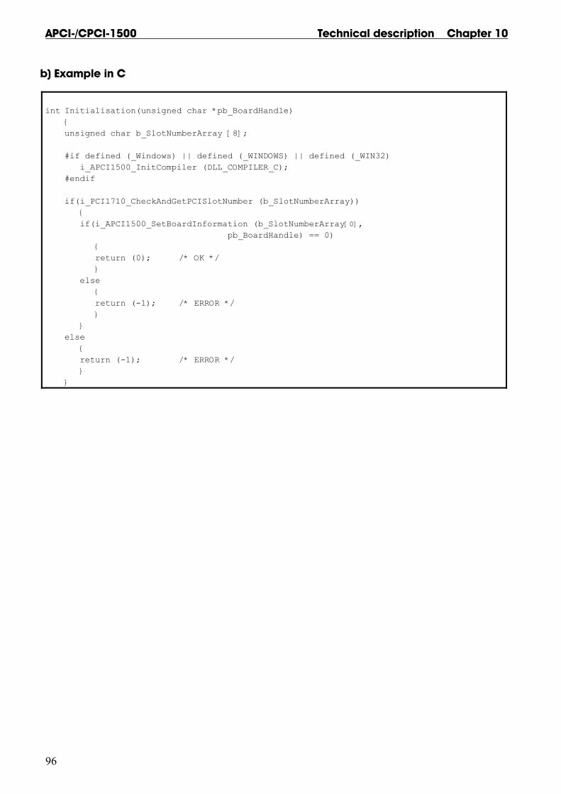
APCI-/CPCI-1500 Technical description Chapter 10
96
b) Example in C
int Initialisation(unsigned char *pb_BoardHandle) { unsigned char b_SlotNumberArray [8]; #if defined (_Windows) || defined (_WINDOWS) || defined (_WIN32) i_APCI1500_InitCompiler (DLL_COMPILER_C); #endif if(i_PCI1710_CheckAndGetPCISlotNumber (b_SlotNumberArray)) { if(i_APCI1500_SetBoardInformation (b_SlotNumberArray[0], pb_BoardHandle) == 0) { return (0); /* OK */ } else { return (-1); /* ERROR */ } } else { return (-1); /* ERROR */ } }
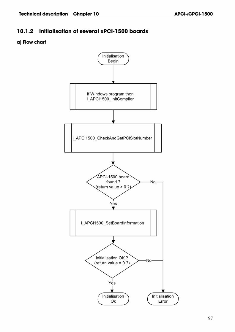
Technical description Chapter 10 APCI-/CPCI-1500
97
10.1.2 Initialisation of several xPCI-1500 boards
a) Flow chart
If Windows program theni_APCI1500_InitCompiler
i_APCI1500_CheckAndGetPCISlotNumber
APCI-1500 boardfound ?
(return value > 0 ?)
i_APCI1500_SetBoardInformation
Initialisation OK ?(return value = 0 ?)
InitialisationBegin
InitialisationOk
Yes
Yes
InitialisationError
No
No

APCI-/CPCI-1500 Technical description Chapter 10
98
b) Example in C
int MoreInitialisation(unsigned char *pb_BoardHandleArray) { int i_NbrOfBoard; int i_Cpt; unsigned char b_SlotNumberArray [8]; #if defined (_Windows) || defined (_WINDOWS) || defined (_WIN32) i_APCI1500_InitCompiler (DLL_COMPILER_C); #endif i_NbrOfBoard = i_PCI1710_CheckAndGetPCISlotNumber (b_SlotNumberArray) if(i_NbrOfBoard > 0) { for (i_Cpt = 0; i_Cpt < i_NbrOfBoard; i_Cpt ++) { if (i_APCI1500_SetBoardInformation (b_SlotNumberArray[i_Cpt], &pb_BoardHandleArray [i_Cpt]) != 0) { break; } } if (i_Cpt == i_NbrOfBoard) { return (i_Cpt); /* Return number of board found */ } else { return (-1); /* ERROR */ } } else { return (-1); /* ERROR */ } }
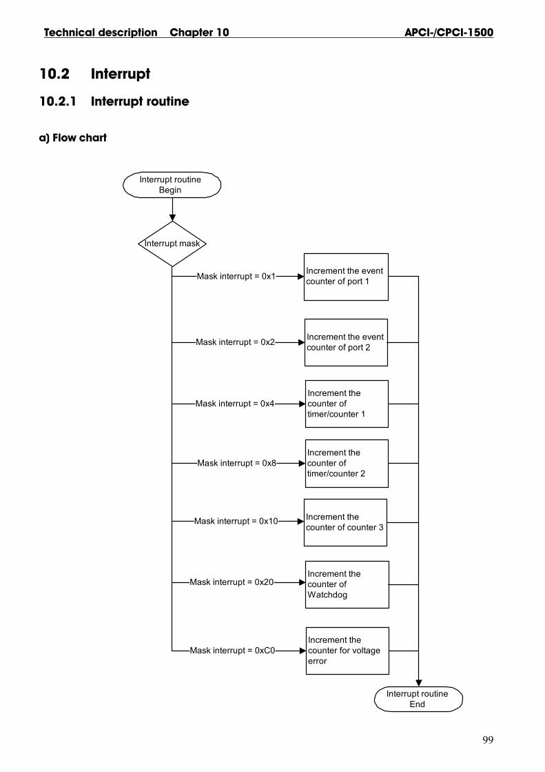
Technical description Chapter 10 APCI-/CPCI-1500
99
10.2 Interrupt
10.2.1 Interrupt routine
a) Flow chart
Interrupt mask
Interrupt routineBegin
Interrupt routineEnd
Increment the event counter of port 1
Increment the event counter of port 2
Mask interrupt = 0x1
Mask interrupt = 0x2
Increment the counter of timer/counter 1
Mask interrupt = 0x4
Increment thecounter of timer/counter 2
Mask interrupt = 0x8
Increment the counter of counter 3
Increment the counter of Watchdog
Increment the counter for voltage error
Mask interrupt = 0xC0
Mask interrupt = 0x10
Mask interrupt = 0x20

APCI-/CPCI-1500 Technical description Chapter 10
100
b) Example in C for DOS and Windows 3.1x
unsigned char b_EventCpt [2], b_TimerCounterCpt [3]; /* Global buffer */ unsigned char b_WatchdogCpt, b_VoltageErrorCpt; _VOID_ v_InterruptRoutine (BYTE_ b_BoardHandle, BYTE_ b_InterruptMask, BYTE_b_InputChannelNbr) { if (b_InterruptMask & 0x1) { /**************************/ b_EventCpt [0] = b_EventCpt [0] + 1; /* Event port 1 interrupt */ } /**************************/ if (b_InterruptMask & 0x1) { /**************************/ b_EventCpt [1] = b_EventCpt [1] + 1; /* Event port 2 interrupt */ } /**************************/ if (b_InterruptMask & 0x4) { /*****************************/ b_TimerCounterCpt [0] = b_TimerCounterCpt [0] + 1; /* Timer/Counter 1 interrupt */ } /*****************************/ if (b_InterruptMask & 0x8) { /*****************************/ b_TimerCounterCpt [1] = b_TimerCounterCpt [1] + 1; /* Timer/Counter 2 interrupt */ } /*****************************/ if (b_InterruptMask & 0x10) { /***********************/ b_TimerCounterCpt [2] = b_TimerCounterCpt [2] + 1; /* Counter 3 interrupt */ } /***********************/ if (b_InterruptMask & 0x20) { /**********************/ b_WatchdogCpt = b_WatchdogCpt + 1; /* Watchdog interrupt */ } /**********************/ if (b_InterruptMask & 0xC0) { /*****************/ b_VoltageErrorCpt = b_VoltageErrorCpt + 1; /* Voltage error */ } /*****************/
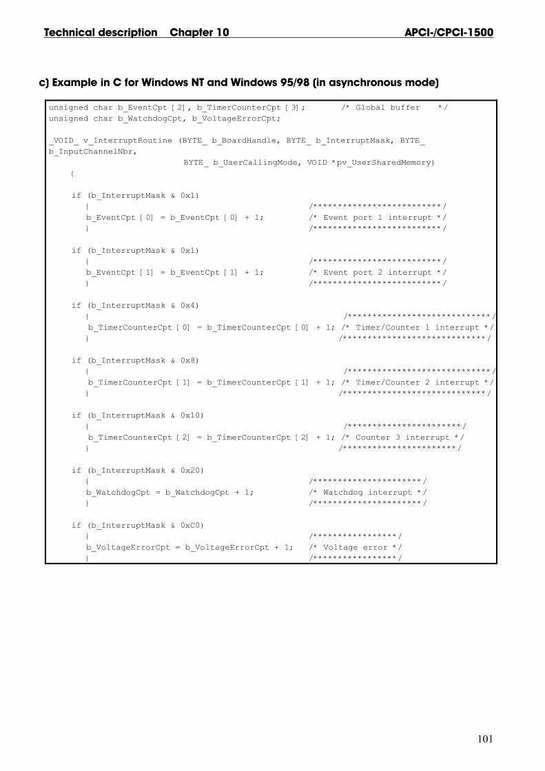
Technical description Chapter 10 APCI-/CPCI-1500
101
c) Example in C for Windows NT and Windows 95/98 (in asynchronous mode)
unsigned char b_EventCpt [2], b_TimerCounterCpt [3]; /* Global buffer */ unsigned char b_WatchdogCpt, b_VoltageErrorCpt; _VOID_ v_InterruptRoutine (BYTE_ b_BoardHandle, BYTE_ b_InterruptMask, BYTE_ b_InputChannelNbr, BYTE_ b_UserCallingMode, VOID *pv_UserSharedMemory) { if (b_InterruptMask & 0x1) { /**************************/ b_EventCpt [0] = b_EventCpt [0] + 1; /* Event port 1 interrupt */ } /**************************/ if (b_InterruptMask & 0x1) { /**************************/ b_EventCpt [1] = b_EventCpt [1] + 1; /* Event port 2 interrupt */ } /**************************/ if (b_InterruptMask & 0x4) { /*****************************/ b_TimerCounterCpt [0] = b_TimerCounterCpt [0] + 1; /* Timer/Counter 1 interrupt */ } /*****************************/ if (b_InterruptMask & 0x8) { /*****************************/ b_TimerCounterCpt [1] = b_TimerCounterCpt [1] + 1; /* Timer/Counter 2 interrupt */ } /*****************************/ if (b_InterruptMask & 0x10) { /***********************/ b_TimerCounterCpt [2] = b_TimerCounterCpt [2] + 1; /* Counter 3 interrupt */ } /***********************/ if (b_InterruptMask & 0x20) { /**********************/ b_WatchdogCpt = b_WatchdogCpt + 1; /* Watchdog interrupt */ } /**********************/ if (b_InterruptMask & 0xC0) { /*****************/ b_VoltageErrorCpt = b_VoltageErrorCpt + 1; /* Voltage error */ } /*****************/

APCI-/CPCI-1500 Technical description Chapter 10
102
d) Example for Windows NT and Windows 95/98 (in synchronous mode)
typedef struct {
unsigned char b_EventCpt [2], b_TimerCounterCpt [3]; unsigned char b_WatchdogCpt, b_VoltageErrorCpt; }str_UserStruct; _VOID_ v_InterruptRoutine (BYTE_ b_BoardHandle, BYTE_ b_InterruptMask, BYTE_b_InputChannelNbr, BYTE_ b_UserCallingMode, VOID *pv_UserSharedMemory) { str_UserStruct * ps_UserStruct = (str_UserStruct *) pv_UserSharedMemory; { if (b_InterruptMask & 0x1) { /* Event port 1 interrupt */ ps_UserStruct->b_EventCpt [0] = ps_UserStruct->b_EventCpt [0] + 1; } if (b_InterruptMask & 0x1) { /* Event port 2 interrupt */ ps_UserStruct->b_EventCpt [1] = ps_UserStruct->b_EventCpt [1] + 1; } if (b_InterruptMask & 0x4) { /* Timer/Counter 1 interrupt */ ps_UserStruct->b_TimerCounterCpt [0] = ps_UserStruct->b_TimerCounterCpt [0] + 1; } if (b_InterruptMask & 0x8) { /* Timer/Counter 2 interrupt */ ps_UserStruct->b_TimerCounterCpt [1] = ps_UserStruct->b_TimerCounterCpt [1] + 1; } if (b_InterruptMask & 0x10) { /* Counter 3 interrupt */ ps_UserStruct->b_TimerCounterCpt [2] = ps_UserStruct->b_TimerCounterCpt [2] + 1; } if (b_InterruptMask & 0x20) { /* Watchdog interrupt */ ps_UserStruct->b_WatchdogCpt = ps_UserStruct->b_WatchdogCpt + 1; } if (b_InterruptMask & 0xC0) { /* Voltage error */ ps_UserStruct-> ps_UserStruct->b_VoltageErrorCpt = b_VoltageErrorCpt + 1; }

Technical description Chapter 10 APCI-/CPCI-1500
103
10.2.2 Timer interrupt
a) Flow chart
Initialisation
Return value = 0
i_APCI1500_CloseBoardHandle
Timer 1 interrupt testBegin
Timer 1 interrupt testEnd
i_APCI1500_SetBoardIntRoutine
Yes
Return value = 0
Yes
i_APCI1500_InitTimerCounter1
Loop
Write number of
interrupt
Until a key is pressed
i_APCI1500_StopTimerCounter1
i_APCI1500_ResetBoardIntRoutine
2
2
i_APCI1500_StartTimerCounter1
1
1

APCI-/CPCI-1500 Technical description Chapter 10
104
b) Example in C for DOS
void main (void)
{
int i_ReturnValue;
unsigned char b_BoardHandle;
if (Initialisation (&b_BoardHandle) == 0)
{
if (i_APCI1500_SetBoardIntRoutineDos (b_BoardHandle, v_InterruptRoutine) == 0)
{
i_ReturnValue = i_APCI1500_InitTimerInputClock (b_BoardHandle,
APCI1500_1_8_KHZ);
printf ("\nTimer input clock initialisation return value = %d", i_ReturnValue);
i_ReturnValue = i_APCI1500_InitTimerCounter1 (b_BoardHandle,
APCI1500_TIMER,
1UL,
APCI1500_CONTINUOUS,
APCI1500_ENABLE);
printf ("\nTimer initialisation return value = %d", i_ReturnValue);
i_ReturnValue = i_APCI1500_StartTimerCounter1 (b_BoardHandle);
printf ("\nTimer start return value = %d", i_ReturnValue);
do
{
printf ("\nTimer interrupt counter = %d", b_TimerCounterCpt [0]);
}
while (!kbhit());
getch ();
i_ReturnValue = i_APCI1500_StopTimerCounter1 (b_BoardHandle);
printf ("\nTimer stop return value = %d", i_ReturnValue);
i_ReturnValue = i_APCI1500_ResetBoardIntRoutine (b_BoardHandle);
printf ("\nReset board interrupt return value = %d", i_ReturnValue);
i_ReturnValue = i_APCI1500_CloseBoardHandle (b_BoardHandle);
printf ("\nClose board handle return value = %d", i_ReturnValue);
}
else
{
printf ("\nInterrupt initialisation error");
i_ReturnValue = i_APCI1500_CloseBoardHandle (b_BoardHandle);
printf ("\nClose board handle return value = %d", i_ReturnValue);
}
}
else
{
printf ("\nBoard initialisation error");
}

Technical description Chapter 10 APCI-/CPCI-1500
105
c) Example in C for Windows 3.1x
void main (void)
{
int i_ReturnValue;
unsigned char b_BoardHandle;
if (Initialisation (&b_BoardHandle) == 0)
{
if (i_APCI1500_SetBoardIntRoutineWin16 (b_BoardHandle, v_InterruptRoutine) == 0)
{
i_ReturnValue = i_APCI1500_InitTimerInputClock (b_BoardHandle,
APCI1500_1_8_KHZ);
printf ("\nTimer input clock initialisation return value = %d", i_ReturnValue);
i_ReturnValue = i_APCI1500_InitTimerCounter1 (b_BoardHandle,
APCI1500_TIMER,
1UL,
APCI1500_CONTINUOUS,
APCI1500_ENABLE);
printf ("\nTimer initialisation return value = %d", i_ReturnValue);
i_ReturnValue = i_APCI1500_StartTimerCounter1 (b_BoardHandle);
printf ("\nTimer start return value = %d", i_ReturnValue);
do
{
printf ("\nTimer interrupt counter = %d", b_TimerCounterCpt [0]);
}
while (!kbhit());
getch ();
i_ReturnValue = i_APCI1500_StopTimerCounter1 (b_BoardHandle);
printf ("\nTimer stop return value = %d", i_ReturnValue);
i_ReturnValue = i_APCI1500_ResetBoardIntRoutine (b_BoardHandle);
printf ("\nReset board interrupt return value = %d", i_ReturnValue);
i_ReturnValue = i_APCI1500_CloseBoardHandle (b_BoardHandle);
printf ("\nClose board handle return value = %d", i_ReturnValue);
}
else
{
printf ("\nInterrupt initialisation error");
i_ReturnValue = i_APCI1500_CloseBoardHandle (b_BoardHandle);
printf ("\nClose board handle return value = %d", i_ReturnValue);
}
}
else
{
printf ("\nBoard initialisation error");
}

APCI-/CPCI-1500 Technical description Chapter 10
106
d) Example in C for Windows NT/95/98 (in asynchronous mode)
void main (void)
{
int i_ReturnValue;
unsigned char b_BoardHandle;
if (Initialisation (&b_BoardHandle) == 0)
{
if (i_APCI1500_SetBoardIntRoutineWin32 (b_BoardHandle, APCI1500_ASYNCHRONOUS_MODE,
0, NULL, v_InterruptRoutine) == 0)
{
i_ReturnValue = i_APCI1500_InitTimerInputClock (b_BoardHandle, APCI1500_1_8_KHZ);
printf ("\nTimer input clock initialisation return value = %d", i_ReturnValue);
i_ReturnValue = i_APCI1500_InitTimerCounter1 (b_BoardHandle, APCI1500_ENABLE);
printf ("\nTimer initialisation return value = %d", i_ReturnValue);
i_ReturnValue = i_APCI1500_StartTimerCounter1 (b_BoardHandle);
printf ("\nTimer start return value = %d", i_ReturnValue);
do
{
printf ("\nTimer interrupt counter = %d", b_TimerCounterCpt [0]);
}
while (!kbhit());
getch ();
i_ReturnValue = i_APCI1500_StopTimerCounter1 (b_BoardHandle);
printf ("\nTimer stop return value = %d", i_ReturnValue);
i_ReturnValue = i_APCI1500_ResetBoardIntRoutine (b_BoardHandle);
printf ("\nReset board interrupt return value = %d", i_ReturnValue);
i_ReturnValue = i_APCI1500_CloseBoardHandle (b_BoardHandle);
printf ("\nClose board handle return value = %d", i_ReturnValue);
}
else
{
printf ("\nInterrupt initialisation error");
i_ReturnValue = i_APCI1500_CloseBoardHandle (b_BoardHandle);
printf ("\nClose board handle return value = %d", i_ReturnValue);
}
}
else
{
printf ("\nBoard initialisation error");
}
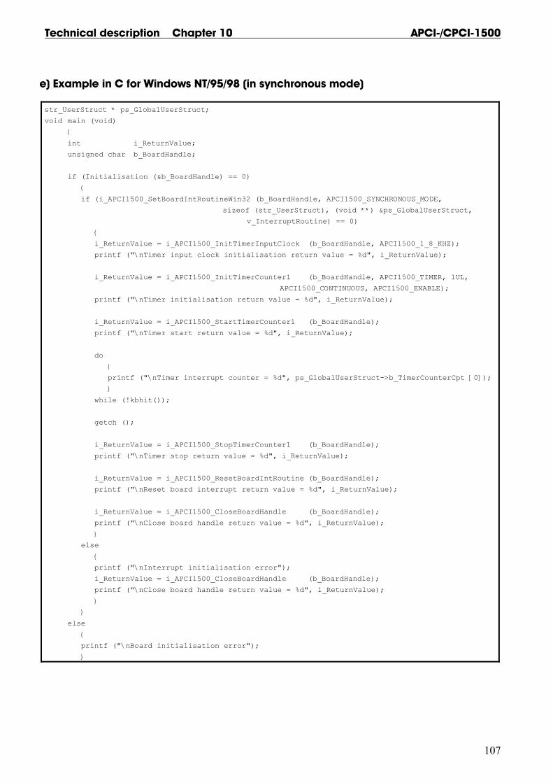
Technical description Chapter 10 APCI-/CPCI-1500
107
e) Example in C for Windows NT/95/98 (in synchronous mode)
str_UserStruct * ps_GlobalUserStruct;
void main (void)
{
int i_ReturnValue;
unsigned char b_BoardHandle;
if (Initialisation (&b_BoardHandle) == 0)
{
if (i_APCI1500_SetBoardIntRoutineWin32 (b_BoardHandle, APCI1500_SYNCHRONOUS_MODE,
sizeof (str_UserStruct), (void **) &ps_GlobalUserStruct,
v_InterruptRoutine) == 0)
{
i_ReturnValue = i_APCI1500_InitTimerInputClock (b_BoardHandle, APCI1500_1_8_KHZ);
printf ("\nTimer input clock initialisation return value = %d", i_ReturnValue);
i_ReturnValue = i_APCI1500_InitTimerCounter1 (b_BoardHandle, APCI1500_TIMER, 1UL,
APCI1500_CONTINUOUS, APCI1500_ENABLE);
printf ("\nTimer initialisation return value = %d", i_ReturnValue);
i_ReturnValue = i_APCI1500_StartTimerCounter1 (b_BoardHandle);
printf ("\nTimer start return value = %d", i_ReturnValue);
do
{
printf ("\nTimer interrupt counter = %d", ps_GlobalUserStruct->b_TimerCounterCpt [0]);
}
while (!kbhit());
getch ();
i_ReturnValue = i_APCI1500_StopTimerCounter1 (b_BoardHandle);
printf ("\nTimer stop return value = %d", i_ReturnValue);
i_ReturnValue = i_APCI1500_ResetBoardIntRoutine (b_BoardHandle);
printf ("\nReset board interrupt return value = %d", i_ReturnValue);
i_ReturnValue = i_APCI1500_CloseBoardHandle (b_BoardHandle);
printf ("\nClose board handle return value = %d", i_ReturnValue);
}
else
{
printf ("\nInterrupt initialisation error");
i_ReturnValue = i_APCI1500_CloseBoardHandle (b_BoardHandle);
printf ("\nClose board handle return value = %d", i_ReturnValue);
}
}
else
{
printf ("\nBoard initialisation error");
}

INDEX APCI-/CPCI-1500
A
INDEX
ADDIREG 15–20 changing the configuration 20 uninstallation 25
board component schemes 8 functions 29–35 handling 3 inserting 12 physical set-up 4
component schemes 8
connecting the peripheral 26–28
connection examples 27–28 peripheral 26 pin connector 26 principle 27
connection cable 1
counter 31, 33–35
diagnostic outputs 32
digital inputs 5, 30–31 circuitry 31 counter 31 interrupt 31
digital outputs 6, 32–33 diagnostic 32
EMC 4
event 33
functions of the board 29–35
gate 34
installation 10–14
intended purpose of the board 1
Internet error analysis 25
interrupt 31, 33
interrupt sources 33
limit values 5–7 energy requirements 5
overflow 33
PC selecting a slot 11
pin connector 26
safety 7
slot selecting a 11 types 11
software 36–94
technical data 4–7
timer 33–35
use, limits of 1
Use, limits of 1


