1 2 3 4 5 Direct Design Handbook for Masonry Structures 6 (TMS 0403-13) 7 8 9 **Includes Committee-approved revisions to TMS 403-10 from Letter Ballots 10 2011-01, 2012-01, 2012-02, and no-protest editorial revisions included in 11 March 28, 2012 DPC Meeting Minutes. 12 13 October 3, 2012 Working Draft 14 15 16 17 18 19 20 21 22 Prepared by the 23 TMS Design Practices Committee 24 25 26 Boulder, CO 27 28 29 Page 1 Page 1
Transcript
1
2
3
4
5
Direct Design Handbook for Masonry Structures 6
(TMS 0403-13) 7
8
9
**Includes Committee-approved revisions to TMS 403-10 from Letter Ballots 10 2011-01, 2012-01, 2012-02, and no-protest editorial revisions included in 11 March 28, 2012 DPC Meeting Minutes. 12 13
John H. Matthys W. Mark McGinley Raymond T. Miller
Michael C. Mota Kurtis K. Siggard
Christine A. Subasic Terence A. Weigel
Corresponding Members2
Subhash C. Anand Jefferson W. Asher Thomas B. Brady John M. Bufford
Richard Filloramo Thomas A. Gangel Thomas A. Hagood
Frederick A. Herget Edwin T. Huston Brian E. Johnson
Gregory R. Kingsley Michael D. Lewis Vilas Mujumdar
Javeed A. Munshi
Malcolm E. Phipps Joseph E. Saliba Narendra Taly
John G. Tawresey Itzhak Tepper
David B. Woodham Daniel Zechmeister
1. Voting members fully participate in Committee activities including responding to correspondence and voting on revisions to this document. 2. Corresponding members monitor Committee activities, but do not have voting privileges.
Technical Activities Committee (To Be Updated)
The Technical Activities Committee (TAC) of The Masonry Society (TMS) is responsible for reviewing, and approving the work of all TMS Technical Committees. As such, they reviewed the drafts of this Direct Design Handbook for Masonry Structures, and have approved revisions based on comments submitted by both TAC and the public. Members of the Technical Activities Committee who assisted with review, development, and approval of this Handbook are:
J. Gregg Borchelt, TAC Chairman
Craig Baltimore John H. Matthys David I. McLean
Jason J. Thompson Rashod R. Johnson
Terence A. Weigel A. Rhett Whitlock
Page 3
Page 3
Synopsis This Handbook provides a direct procedure for the structural design of single-story concrete masonry structures. The procedure is based on the strength design provisions of TMS 402-11/ACI 530-11/ASCE 5-11 and the corresponding loading requirements of ASCE 7-10. It is written in such a form that it may be adopted by reference in a general building code. Among the topics covered are reference standards, definitions and notations, site limitations, architectural limitations, loading limitations, material and construction requirements, direct design procedure, optional modifications to the direct design procedure, specifications, and details. The Commentary to this Standard presents background analysis, details, and Committee considerations used to develop the Standard. While not part of the legal requirements of this Standard, an Appendix providing an example of how to use the direct design procedure for a typical masonry building is provided following the Commentary. Keywords Beams; building codes; cements; clay brick; compressive strength; concrete block; concrete masonry; construction; control joints; design handbook; detailing; grout; direct design; grouting; handbook; high wind; joints; loads (forces); masonry; masonry cement; masonry load-bearing walls; masonry mortars; masonry units; masonry walls; mortars; portland cement; portland cement-lime mortar; reinforced masonry; rebar; reinforcing steel; seismic requirements; shear strength; simplified design; specifications; splicing; stresses; strength design; structural analysis; structural design; unreinforced masonry; veneers; walls Future Updates and Possible Errata To access information on possible future updates or errata on this handbook, see http://www.masonrysociety.org/html/resources/directdesign/.
Page 4
Page 4
Table of Contents (To Be Updated)
Direct Design Procedure Reference Guide ............................................... Inside, Front Cover Chapter 1 General ................................................................................................................. 1 1.1 – Scope .............................................................................................................................. 1 1.2 – Standards cited .................................................................................................................... 1 1.3 – Definitions ............................................................................................................................ 1 1.4 – Notations ............................................................................................................................. 2 Chapter 2 Limitations ........................................................................................................... 5 2.1– Site Conditions ...................................................................................................................... 5 2.2 – Architectural Conditions ....................................................................................................... 6 2.3 – Loading Conditions .............................................................................................................. 7 2.4 –Material and Construction Requirements .............................................................................. 8 Chapter 3 Procedure ................................................................................................................... 9 3.1 – General .............................................................................................................................. 9 3.2 – Direct Design Procedure ...................................................................................................... 9 Chapter 4 Modifications ..................................................................................................... 69 4.1 – Alternative Site Classes ..................................................................................................... 69 4.2 – Alternative Spectral Acceleration Maps ............................................................................. 69 4.3 – Masonry Veneers Installed over Lightweight Concrete Masonry Units .............................. 69 4.4 – Masonry Veneers Installed over Medium Weight and Normal Weight Concrete Masonry Units ............................................................. 71 4.5 – Alternative Topography ...................................................................................................... 71 Chapter 5 Specification ...................................................................................................... 77 Chapter 6 Details ................................................................................................................. 79
Page 5
Page 5
Commentary Chapter 1 General ........................................................................................ C-1 C1.1 – Scope .......................................................................................................................... C-1 C1.2 – Standards cited ............................................................................................................. C-2 C1.3 – Definitions ...................................................................................................................... C-2 C1.4 – Notations ....................................................................................................................... C-4 References ................................................................................................................................ C-4 Commentary Chapter 2 Limitations ................................................................................... C-5 C2.1– Site Conditions ............................................................................................................... C-5 C2.2 – Architectural Conditions ................................................................................................ C-6 C2.3 – Loading Conditions ...................................................................................................... C-10 C2.4 –Materials and Construction Requirements ................................................................... C-11 References .............................................................................................................................. C-13 Commentary Chapter 3 Procedure .................................................................................. C-15 C3.1 – General ................................................................................................................... C-15 C3.2 – Direct Design Procedure ............................................................................................. C-15 References .............................................................................................................................. C-30 Commentary Chapter 4 Modifications ............................................................................. C-31 C4.1 – Alternative Site Classes .............................................................................................. C-31 C4.2 – Alternative Spectral Acceleration Maps ....................................................................... C-31 C4.3 – Masonry Veneers Installed over Lightweight Concrete Masonry Units ....................... C-31 C4.4 – Masonry Veneers Installed over Medium Weight and Normal Weight Concrete Masonry Units ......................................................... C-32 C4.5 – Alternative Topography ............................................................................................... C-32 Commentary Chapter 5 Specification ............................................................................. C-33 Commentary Chapter 6 Details ........................................................................................ C-35 Appendix Direct Design Procedure Design Example ....................................................... A-1
Page 6
Page 6
DIRECT DESIGN HANDBOOK FOR MASONRY STRUCTURES 1
Chapter 1 1
General 2 3 1.1 – Scope 4 5 This Direct Design Handbook for Masonry Structures, herein referred to as the Handbook, outlines a 6 direct procedure for the structural design of single-story, concrete masonry structures. The procedure shall 7 be permitted to be used to design concrete masonry subjected to factored combinations of dead, roof live, 8 wind, seismic, snow and rain loads. The procedure outlined in this Handbook is based on the strength 9 design provisions of the 2011 Building Code Requirements for Masonry Structures (TMS 402-11/ACI 10 530-11/ASCE 5-11) and the 2010 ASCE 7 Minimum Design Loads for Buildings and Other Structures 11 (ASCE 7-10). 12 13 14 1.2 – Standards cited 15 16 Standards of the American Concrete Institute, the Structural Engineering Institute of the American 17 Society of Civil Engineers, ASTM International, and The Masonry Society cited in this document are 18 listed below with their serial designations, including year of adoption or revision, and are declared to be 19 part of this Handbook as if fully set forth in this document. 20 21 TMS 402-11/ACI 530-11/ASCE 5-11 – Building Code Requirements for Masonry Structures, referenced 22
herein as the MSJC Code 23
TMS 602-11/ACI 530.1-11/ASCE 6-11 – Specification for Masonry Structures, referenced herein as the 24 MSJC Specification 25
ASCE 7-10 – Minimum Design Loads for Buildings and Other Structures, referenced herein as ASCE 7 26
ASTM A615/A615M-09 – Standard Specification for Deformed and Plain Carbon-Steel Bars for 27 Concrete Reinforcement 28
ASTM A706/A706M-08a – Standard Specification for Low-Alloy Steel Deformed and Plain Bars for 29 Concrete Reinforcement 30
ASTM A996/A996M-09 – Standard Specification for Rail-Steel and Axle-Steel Deformed Bars for 31 Concrete Reinforcement 32
ASTM C90-08 – Standard Specification for Loadbearing Concrete Masonry Units 33
ASTM C270-08 – Standard Specification for Mortar for Unit Masonry 34
ASTM C476-09 – Standard Specification for Grout for Masonry 35
ASTM C1314-07 – Standard Test Method for Compressive Strength of Masonry Prisms 36
37 1.3 – Definitions 38 39 Terms defined in the MSJC Code and MSJC Specification shall apply to the design of masonry designed 40 in accordance with this Handbook. The following terms, as used in this Handbook, shall have the 41 following meaning: 42 43 B Bars – horizontal reinforcing bars located at the bottom of masonry beams over openings, mirrored at 44
the diaphragm level over the openings. 45
Page 7
Page 7
2 DIRECT DESIGN HANDBOOK FOR MASONRY STRUCTURES
C Bars – reinforcing bars located at the level at which the diaphragm is connected and used to resist 1 diaphragm chord tension. 2
Designated shear wall segment – a portion of a wall that is continuous in plan, uninterrupted from the 3 foundation to the diaphragm elevation, and is used to resist in-plane shear loads. 4
E Bars – vertical reinforcing bars located adjacent to the edge of openings. 5
Exposure Category – Wind exposure category as defined in Section 26.7 of ASCE 7. 6
H Bars – horizontal reinforcing bars. 7
Header panel – the portion of masonry above an opening. 8
J Bars – vertical reinforcing bars located at the jamb of an opening, mirrored at the opposite end of the 9 wall segment. 10
LFRS – Lateral force-resisting system. 11
Non-designated shear wall segment – a portion of a wall that is continuous in plan, uninterrupted from the 12 foundation to the diaphragm elevation, but is not relied upon in the direct design method to resist 13 in-plane shear loads. 14
Non-participating walls – walls that are isolated so that in-plane lateral forces are not imparted to these 15 elements. 16
O Bars – horizontal reinforcing bars located in header panels above an opening or sill panels below an 17 opening. 18
Risk Category – Risk category of the structure determined in accordance with Table 1.5-1 of ASCE 7. 21
SDC – Seismic design category. 22
Sill panel – the portion of masonry below an opening. 23
SRMSW – Special reinforced masonry shear wall. 24
T Bars – horizontal reinforcing bars located at the top of a parapet. 25
V Bars – vertical reinforcing bars. 26
27 28 1.4 – Notations 29 30 A = area of a building elevation perpendicular to the principal plan direction under 31
consideration, ft2 (m2). 32
Cs = seismic response coefficient as determined by Table 3.2-4. 33
Cw = wind response coefficient as determined by Table 3.2-3, lb/ft2 (kPa). 34
ds = depth of water on the undeflected roof up to the inlet of the secondary drainage system 35 when the primary drainage system is blocked (i.e., the static head), in. (mm). 36
dh = additional depth of water on the undeflected roof above the inlet of the secondary drainage 37 system at its design flow (i.e., the hydraulic head), in. (mm). 38
g = acceleration due to gravity, ft/s2 (m/s2). 39
Page 8
Page 8
DIRECT DESIGN HANDBOOK FOR MASONRY STRUCTURES 3
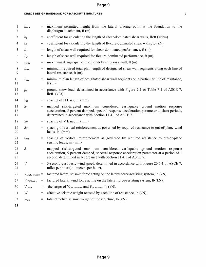
hmax = maximum permitted height from the lateral bracing point at the foundation to the 1 diaphragm attachment, ft (m). 2
k1 = coefficient for calculating the length of shear-dominated shear walls, lb/ft (kN/m). 3
k2 = coefficient for calculating the length of flexure-dominated shear walls, lb (kN). 4
L1 = length of shear wall required for shear-dominated performance, ft (m). 5
L2 = length of shear wall required for flexure-dominated performance, ft (m). 6
Ljoist = maximum design span of roof joists bearing on a wall, ft (m). 7
Lreq = minimum required total plan length of designated shear wall segments along each line of 8 lateral resistance, ft (m). 9
Lseg = minimum plan length of designated shear wall segments on a particular line of resistance, 10 ft (m). 11
pg = ground snow load, determined in accordance with Figure 7-1 or Table 7-1 of ASCE 7, 12 lb/ft2 (kPa). 13
SH = spacing of H Bars, in. (mm). 14
SS = mapped risk-targeted maximum considered earthquake ground motion response 15 acceleration, 5 percent damped, spectral response acceleration parameter at short periods, 16 determined in accordance with Section 11.4.1 of ASCE 7. 17
SV = spacing of V Bars, in. (mm). 18
SV1 = spacing of vertical reinforcement as governed by required resistance to out-of-plane wind 19 loads, in. (mm). 20
SV2 = spacing of vertical reinforcement as governed by required resistance to out-of-plane 21 seismic loads, in. (mm). 22
S1 = mapped risk-targeted maximum considered earthquake ground motion response 23 acceleration, 5 percent damped, spectral response acceleration parameter at a period of 1 24 second, determined in accordance with Section 11.4.1 of ASCE 7. 25
V = 3-second gust basic wind speed, determined in accordance with Figure 26.5-1 of ASCE 7, 26 miles per hour (kilometers per hour). 27
VLFRS-seismic = factored lateral seismic force acting on the lateral force-resisting system, lb (kN). 28
VLFRS-wind = factored lateral wind force acting on the lateral force-resisting system, lb (kN). 29
VLFRS = the larger of VLFRS-seismic and VLFRS-wind, lb (kN). 30
W = effective seismic weight resisted by each line of resistance, lb (kN). 31
Wtot = total effective seismic weight of the structure, lb (kN). 32
33
Page 9
Page 9
4 DIRECT DESIGN HANDBOOK FOR MASONRY STRUCTURES
1
2
3
4
5
6
7
This Page Intentionally Left Blank8
Page 10
Page 10
DIRECT DESIGN HANDBOOK FOR MASONRY STRUCTURES 5
Chapter 2 1
Limitations 2 3
If the limitations specified in Chapter 2 are satisfied, use of this Handbook to perform the structural 4 design of concrete masonry buildings shall be permitted. 5 6 Any segment, member, or portion of a masonry structure that does not meet the limitations of Chapter 2 7 shall be designed in accordance with the legally adopted building code provided each of the following 8 conditions are met: 9 10
a) The strength and stiffness compatibility between the elements designed in accordance with 11 the legally adopted building code and the masonry designed in accordance with this 12 Handbook is verified; 13 14
b) The load path through the masonry designed in accordance with this Handbook is not 15 interrupted; and 16
17 c) Loads are not transferred from the elements designed in accordance with the legally adopted 18
building code into the masonry designed in accordance with this Handbook. 19 20 21 2.1– Site Conditions 22 23
2.1.1 Ground Snow Load – The ground snow load, pg, as given in Figure 7-1 of ASCE 7, shall not 24 exceed 60 lb/ft2 (2.9 kPa). 25
26 2.1.2 Basic Wind Speed – The basic wind speed (3-second gust), V, as given in Figure 26.5-1 of 27
ASCE 7, shall not exceed 150 mph (241 kph). 28 29 2.1.3 Exposure Category – The exposure category, as defined in Section 26.7 of ASCE 7, shall be 30
Exposure Category B or C. 31 32 2.1.4 Topography – The location of the structure shall comply with Section 2.1.4.1 or the basic 33
wind speed shall be modified in accordance with Section 2.1.4.2. 34 35 2.1.4.1 The structure shall not be located in the upper one-half of a hill or ridge or near the 36
crest of an escarpment whose height is greater than 60 ft (18.3 m) for Exposure Category B 37 conditions nor greater than 15 ft (4.6 m) for Exposure Category C conditions. 38
39 2.1.4.2 The basic wind speed (3-second gust), V, shall be determined in accordance with 40
Table 2.1-1. 41 42 2.1.5 Mapped Spectral Acceleration for Short Periods – The mapped spectral acceleration for short 43
period structures, SS, determined in accordance with Section 11.4.1 of ASCE 7, shall not 44 exceed 3.0g. 45
46 47 48 49 50 51 52
Page 11
Page 11
6 DIRECT DESIGN HANDBOOK FOR MASONRY STRUCTURES
1 Table 2.1-1 – Basic Wind Speed Modification for Topographic Wind Speed Up Effect a, b
Topographic Feature
Basic Wind Speed from
ASCE 7 Figure 26.5-1
Average Slope of the Top Half of the Topographic Feature:
0.10 0.125 0.15 0.175 0.20 0.23 0.25 or greater
Required Basic Wind Speed, Modified for Topographic Wind Speed Up:
2 a Table values shall be permitted to be interpolated. 3 b The provisions of this Handbook shall not be used where the modified basic wind speed exceeds 200 4
mph (322 kph). Values of the modified basic wind speed greater than 200 mph (322 kph) are shown 5 only to aid in interpolation. 6
7 8
2.1.6 Mapped Spectral Acceleration for 1-Second Periods– The mapped spectral acceleration for 1-9 second period structures, S1, determined in accordance with Section 11.4.1 of ASCE 7, shall 10 not exceed 1.25g. 11
12 2.1.7 Site Class – The Site Class, determined in accordance with Chapter 20 of ASCE 7, shall be 13
A, B, C, or D. 14 15
16
Page 12
Page 12
DIRECT DESIGN HANDBOOK FOR MASONRY STRUCTURES 7
2.2 – Architectural Conditions 1 2
2.2.1 Number of Stories –The building shall be a one-story structure. 3 4 2.2.2 Walls – All masonry walls shall be single-wythe, constructed of concrete masonry units 5
having a nominal thickness of 8 in. (203 mm). Walls shall be provided in at least two lines in 6 each of the two principal, perpendicular plan directions. 7
8 2.2.3 Height – Tops of walls, parapets and roof peaks shall not be higher than 30 ft (9.1 m) above the 9
finished grade elevation adjacent to the structure. The vertical span of walls, measured between 10 points of lateral bracing, shall not be less than 4 ft (1.2 m) and shall not exceed 30 ft (9.1 m). 11
12 2.2.4 Parapets – The cantilevered height of parapets, measured from diaphragm attachment to the 13
top of the parapet, shall not exceed 4 ft (1.2 m). For walls with a vertical span less than 12 ft 14 (3.7 m), the height of parapets shall not exceed the vertical span of the wall divided by 3. 15
16 2.2.5 Wall Openings – Openings in walls shall be rectangular. The sides of openings shall be 17
oriented vertically. Vertically spanning wall segments between openings and horizontally 18 spanning wall segments above and below openings shall be designed in accordance with 19 Chapter 3. The location of openings in plan shall not overlap. Control joints shall be provided 20 on both sides of each opening in a masonry element designed in accordance with this 21 Handbook. 22
23 2.2.6 Penetrations – Penetrations through masonry walls designed in accordance with this 24
Handbook shall not exceed 6 in. (152 mm) in any dimension at the face of the wall and shall 25 not interrupt reinforcement required by Chapter 3. The cumulative area of penetrations shall 26 not exceed 144 in.2 (0.093 m2) in any 10 ft2 (0.93 m2) of wall surface area. 27
28 2.2.7 Roof Diaphragms – The roof system shall consist of one or more flexible diaphragms and 29
shall meet the following requirements: 30 The maximum plan dimension of a single diaphragm shall not exceed 200 ft (61.0 m). 31 Each roof diaphragm shall be rectangular in plan dimensions. 32 The larger plan dimension of a diaphragm shall not exceed four times the shorter plan 33
dimension of the diaphragm. 34 A roof area shall not be designated as a diaphragm unless the area is surrounded by, 35
and connected to, masonry walls along all four sides of the diaphragm. Such 36 anchorage shall be designed in accordance with the MSJC Code to transfer the 37 required forces from the diaphragm into the walls and from the walls into the 38 diaphragm. 39
Roof diaphragms shall be anchored to masonry walls at a location that coincides with 40 a reinforced masonry bond beam. 41
A designated shear wall segment shall be provided at each corner of a diaphragm in 42 both principal plan directions. 43
The maximum area of each opening in the roof diaphragm shall not exceed ten 44 percent of the gross roof diaphragm area. 45
The maximum dimension of each opening in the roof diaphragm shall not exceed ten 46 percent of the smaller plan dimension of the roof diaphragm. 47
The sum of the opening areas in a roof diaphragm shall not exceed 20 percent of the 48 gross roof diaphragm area. 49
50
Page 13
Page 13
8 DIRECT DESIGN HANDBOOK FOR MASONRY STRUCTURES
2.2.8 Roof Slope – The slope of the finished roof surface shall not be less than 1/4 inch per foot 1 (20.8 mm/m) and shall not exceed 12 in. per foot (1,000 mm/m). Where the ground snow 2 load is greater than 25 lb/ft2 (1.2 kPa), the roof shall not have a curved, multiple folded plate, 3 sawtooth, barrel vault, or dome configuration. 4
5 2.2.9 Changes in Diaphragm Elevation – It shall not be permitted to step a roof diaphragm within 6
the perimeter of the diaphragm. The difference in elevation between adjacent diaphragms 7 plus the height of the upper parapet shall not create a projection above the lower roof that 8 exceeds the maximum permitted parapet height of 4 ft (1.2 m). The projection shall be 9 measured vertically from the top-of-roof on the lower diaphragm to the top-of-masonry on 10 the adjacent diaphragm. Where the ground snow load does not exceed 25 lb/ft2 (1.2 kPa), 11 non-slippery upper roofs with a slope greater than 2:12 that could shed snow on a lower roof 12 and slippery roofs with a slope greater than 1/4:12 that could shed snow on a lower roof shall 13 have a maximum horizontal distance from the eave to the ridge of 42 ft. Where the ground 14 snow load exceeds 25 lb/ft2 (1.2 kPa), the upper roof shall not be permitted to shed snow on a 15 lower roof. 16
17 2.2.10 Joists – The spacing of roof joists shall not exceed 6 ft (1.8 m). Joist span lengths, from the 18
centerline of support to the opposing centerline of support, shall not exceed 60 ft (18.3 m). 19 Joists shall not support a tributary area greater than the span length multiplied by the joist 20 spacing. Masonry shall not be used to support reactions from tributary areas greater than that 21 supported by a joist. 22
23 2.2.11 Roof Drainage – The elevation of all secondary drainage inlets shall be established so that the 24
sum of ds and dh, as defined in Section 8.1 of ASCE 7, does not exceed 5.5 in. (139 mm). 25 26 2.2.12 Isolation of Features – Features such as canopies, signs, and overhangs shall be structurally 27
isolated from the masonry. Wall finishes shall be permitted to be attached, anchored, or 28 adhered to the masonry wall system provided that: 29
the finish does not extend farther than 6 in. (152 mm) from the face of the masonry; 30 and 31
the average installed weight of all finishes does not exceed 3 lb/ft2 (0.14 kPa) over 32 the area to which it is attached. 33
The weight of all installed finishes shall be included in the effective seismic weight, W. 34 35
2.2.13 Simplified Wind Load Procedure Limitations – The limitations of Section 28.6.2 of ASCE 7 36 shall be met. 37
38 2.2.14 Veneers – Masonry veneers shall comply with the requirements of Chapter 6 of the MSJC 39
Code and shall have an installed weight that does not exceed 35 lb/ft2 (1.68 kPa). 40 41
2.3 – Loading Conditions 42 43
2.3.1 Load Types – The provisions outlined in this Handbook shall not be applied to the design of 44 structures that include design loads other than roof dead loads, roof live loads, snow loads, 45 wind loads, seismic loads, and rain loads. 46
47 2.3.2 Roof Dead Load – The roof dead load shall not be less than 2 lb/ft2 (0.1 kPa) and shall not 48
exceed 30 lb/ft2 (1.4 kPa). 49 50 2.3.3 Roof Live Load – The roof live load, as determined in accordance with Section 4.8 of 51
ASCE 7, shall not exceed 20 lb/ft2 (1.0 kPa). 52
Page 14
Page 14
DIRECT DESIGN HANDBOOK FOR MASONRY STRUCTURES 9
2.3.4 Eccentricity of Roof Loads – The maximum eccentricity of applied roof loads shall not 1 exceed 1.25 in. (31.8 mm). Eccentrically applied roof loads from opposite sides of interior 2 load-bearing walls shall not be applied to the same half of the wall cross-section. 3
4 5
2.4 –Material and Construction Requirements 6 7
2.4.1 Units – Concrete masonry units having a nominal thickness of 8 in. (203 mm) and complying 8 with ASTM C90 shall be used. The units shall be laid in running bond construction. The 9 density of the concrete masonry units shall not exceed 135 lb/ft2 (2,162 kg/m3). 10
11 2.4.2 Mortar – Type S mortar complying with ASTM C270 and Table 2.4-1 shall be used. The 12
specified mortar joint thickness shall be 3/8 in. (9.5 mm). 13 14 15 Table 2.4-1 – Permitted Mortar for Seismic Design Category
16 17 2.4.3 Reinforcement – Unless designing unreinforced masonry, the size of reinforcement, including 18
dowels but excluding bed joint reinforcement and lintel stirrups, shall be No. 5 (M#16), 19 Grade 60 (420 MPa) reinforcement. The spacing of No. 5 (M#16) bars shall not be less than 20 16 in. (406 mm) and shall not exceed 10 ft (3.0 m). Vertical reinforcement shall extend the 21 full height of the masonry element in which it is required, less cover distances. Horizontal 22 reinforcement shall extend the full length of the masonry element in which it is required, less 23 cover distances. Shear stirrups used in the construction of lintels shall be No. 3 (M#10), 24 Grade 60 (420 MPa) reinforcement. The spacing of lintel stirrups shall not exceed 8 in. 25 (203 mm). 26
27 2.4.4 Grout – Grout shall comply with ASTM C476. Walls shall be fully grouted if the spacing of 28
either the vertical reinforcement or the horizontal bond beam reinforcement is 16 in. 29 (406 mm). Walls shall be partially grouted if the spacing of the vertical reinforcement and the 30 horizontal bond beam reinforcement are both greater than 16 in. (406 mm). 31
32 2.4.5 Specifications – The construction documents shall contain specifications that meet or exceed 33
the requirements of Chapter 5. 34 35 2.4.6 Details – The detailing requirements of Chapter 6 appropriate to the project shall be provided 36
in the contract documents. 37 38 39 40
41
Page 15
Page 15
10 DIRECT DESIGN HANDBOOK FOR MASONRY STRUCTURES
Chapter 3 1
Procedure 2 3
3.1 – General 4 5 Design of masonry in accordance with this Handbook shall comply with the procedure given in Chapter 6 3. In each step, the design variables in boxes shall be determined by the user. Table references shown in 7 shaded highlight denote tables containing design information. Tabulated values shall not be interpolated 8 unless explicitly permitted by a footnote to the table. 9 10 Walls designed in accordance with this Handbook shall be configured and detailed in accordance with the 11 tables of Chapter 3 and, when reinforcement is required by those tables, reinforcement shall be detailed as 12 illustrated in Figure 3.1-1. 13 14
17 18 3.2 – Direct Design Procedure 19 20 1. Using ASCE 7, the following design requirements shall be determined: 21 22 1A The Risk Category , based on ASCE 7 Table 1.5-1. 23 24 1B The Ground Snow Load, pg , using ASCE 7 Figure 7-1 or ASCE 7 Table 7-1. 25 26 1C The 3-Second Gust Basic Wind Speed, V , using ASCE 7 Figure 26.5-1. 27 28 1D The Exposure Category , using Section 26.7 of ASCE 7. 29 30
1E The mapped spectral acceleration for short periods, SS , in units of g , by dividing the values 31 on ASCE 7 Figure 22-1, 22-3, 22-5, or 22-6 by 100. 32
33
Page 16
Page 16
DIRECT DESIGN HANDBOOK FOR MASONRY STRUCTURES 11
1F The mapped spectral acceleration for a 1-second period, S1 , in units of g , by dividing the 1 values on ASCE 7 Figure 22-2, 22-4, 22-5, or 22-6 by 100. 2
3 2. If the site-specific condition limitations of Section 2.1 of this Handbook are not met, the procedure 4
in this Handbook shall not be used. If Section 2.1 is satisfied, a building configuration that satisfies 5 the architectural, loading, and construction conditions of Chapter 2 shall be developed. 6
7 3. Based on SS and S1, the Seismic Design Category, SDC , shall be determined using: 8
Table 3.2-1(1) for Site Class A; 9 Table 3.2-1(2) for Site Class B; 10 Table 3.2-1(3) for Site Class C; or 11 Table 3.2-1(4) for Site Class D; 12
13 4. Using Table 3.2-2 of this Handbook, and based on the SDC, determine which Lateral Force 14
Resisting Systems, or LFRS options, are permitted. In each principal plan direction of each 15 rectangular roof diaphragm of the building, a single LFRS option must be selected. 16
17 5. In each principal plan direction of the building, divide the roof plan into rectangular roof 18
diaphragms with masonry wall lines on each side. The designation of diaphragms shall be permitted 19 to be different in each principal plan direction. Walls inside the perimeter of a diaphragm are 20 permitted to be connected to that diaphragm only if they are perpendicular to the plan direction 21 under consideration or if they are detailed as non-participating walls. In each principal plan 22 direction, and for each diaphragm designated for that direction, complete the following steps: 23
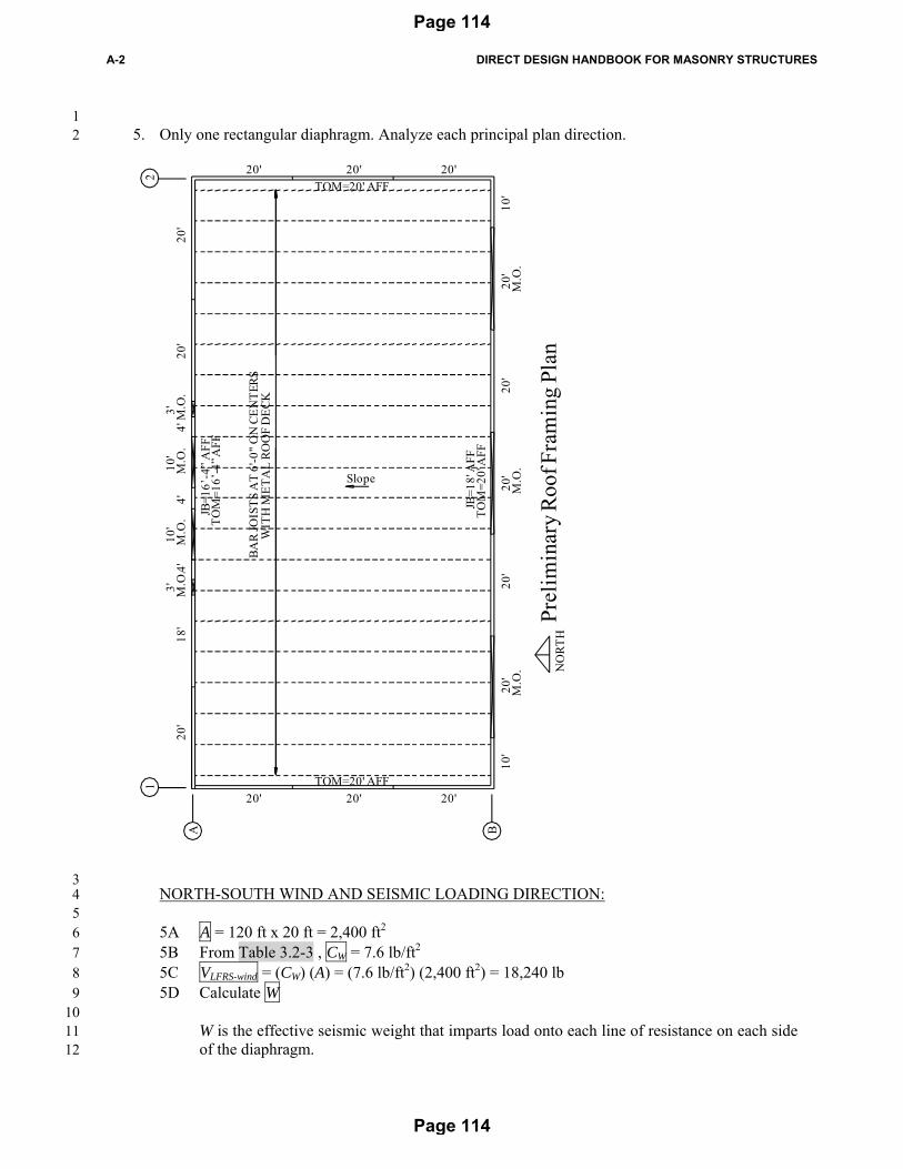
24 5A Calculate the area of the projected building elevation perpendicular to the principal plan 25
direction under consideration, A , in units of square feet (square meters). This area is the 26 product of the plan dimension of the diaphragm perpendicular to the direction under 27 consideration, and the average vertical dimension to the top of the masonry walls defining 28 that diaphragm and oriented perpendicular to the direction under consideration or the top of 29 the roof diaphragm, whichever is greater. 30
31 5B Using Table 3.2-3 of this Handbook, and based on V from Step 1, obtain the Wind Response 32
Coefficient, CW . 33 34 5C Multiply CW by A to calculate the lateral force on each line of lateral resistance in the Lateral 35
Force Resisting System due to wind, VLFRS-wind . 36 37 5D Calculate the effective seismic weight, W , resisted by each line of lateral resistance. 38 39 5E With SS and S1 from Step 1, the Seismic Design Category from Step 3, and an assumed LFRS 40
from the LFRS Options, use Table 3.2-4 of this Handbook to obtain the corresponding 41 Seismic Response Coefficient, CS . Table 3.2-4(1) shall be used for Risk Category I or II 42 structures. Table 3.2-4(2) shall be used for Risk Category III structures. Table 3.2-4(3) shall 43 be used for Risk Category IV structures. 44
45 This Direct Design Procedure permits the following LFRS Options, listed in order of 46
increasing prescriptive reinforcement along with the value of the seismic response 47 modification coefficient, R, corresponding to each option. 48
Special Reinforced Masonry Shear Walls (R = 5.0) 1 2 5F Multiply CS by W to calculate the lateral force on each of the two lines of resistance in the 3
Lateral Force Resisting System due to seismic loads, VLFRS-seismic . 4 5 5G Determine the governing lateral load on the Lateral Force Resisting System, VLFRS , as the 6
greatest of VLFRS-wind and VLFRS-seismic . 7 8 5H In the following sub-steps, determine the maximum permitted spacing of the V Bars for each 9
wall, as governed by out-of-plane wind and seismic loads. Unreinforced masonry is permitted 10 only if a special mechanical anchorage system is provided to resist all net axial uplift. The 11 mechanical anchorage system is not permitted to transfer force to the masonry wall. 12 Unreinforced masonry walls are not permitted to have parapets. 13 14 5H.1 For each wall line that is parallel to the direction under consideration, determine the 15
maximum span of the joists bearing on that wall line, Ljoist , and the maximum wall 16 height, hmax . For walls with no joist bearing, if the first parallel joist is spaced close 17 enough to the wall that the deck can cantilever past the joist to resist wind uplift, Ljoist 18 shall be permitted to be considered equal to 0 ft (0 m) (No Joist). 19
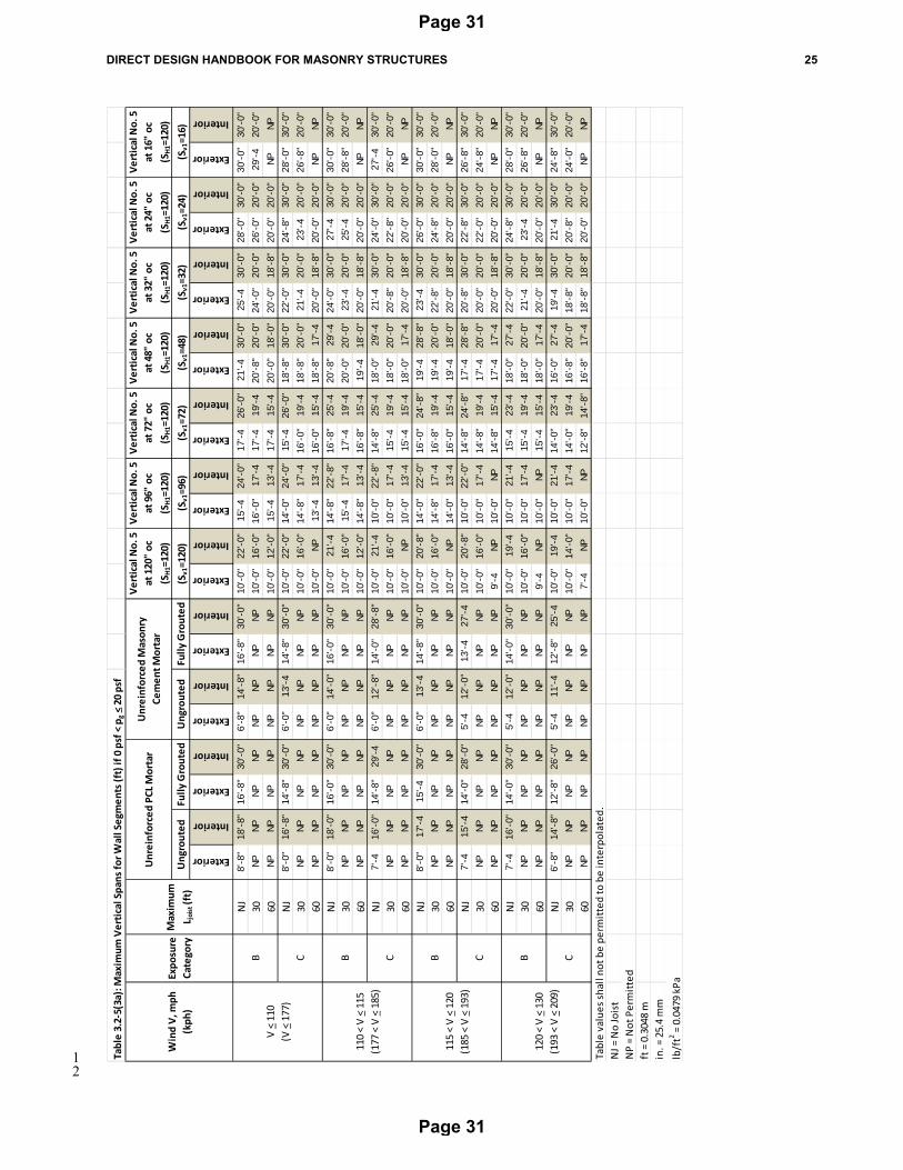
20 5H.2 Determine which of Tables 3.2-5(1) to Table 3.2-5(4) is the appropriate Table 3.2-5, 21
based on comparing pg from Step 1 to the design pg in the table headings. Using the 22 selected Table 3.2-5 and the value of V from Step 1, the Risk Category, the Exposure 23 Category, Ljoist, and whether the wall is in an interior or exterior condition, determine 24 the maximum permitted spacing of vertical reinforcement, SV1. The greatest spacing 25 that permits a vertical span greater than the actual vertical span is the maximum 26 permitted spacing of the V Bars as governed by out-of-plane wind load, SV1 . If 27 vertical bars are used, horizontal H Bars shall be spaced at a maximum of 120 in. 28 (3,048 mm) on center. 29
30 5H.3 Using Table 3.2-6, and based on SS , Ljoist , hmax, and whether the wall is in an interior 31
or an exterior condition, determine the maximum permitted spacing of vertical 32 reinforcement, SV2. The greatest spacing that permits a vertical span greater than the 33 actual vertical span is the maximum permitted spacing of the V Bars as governed by 34 out-of-plane seismic load, SV2 . If vertical bars are used, horizontal H Bars shall be 35 spaced at a maximum of 120 in. (3,048 mm) on center. 36
37 5I In the following sub-steps, select the spacing of the V Bars and of the H Bars for each line of 38
resistance against in-plane seismic and wind loads. 39 40
5I.1 Using Table 3.2-7, determine the applicable Lateral Force Coefficients from Table 41 3.2-8. This determination is based on Vwind and the largest value of Ljoist on the line of 42 resistance. Assume interior conditions, unless the entire plan length of the designated 43 shear walls along the line of resistance is exterior. 44
45 5I.2 Pick an appropriate value for Lseg . The minimum length of shear wall segments shall 46
not be less than 2 ft (0.61 m). 47 48 5I.3 Using Table 3.2-8, determine the resistance coefficients k1 and k2 for the most critical 49
of the wall segments comprising the line of resistance. 50 51
Page 18
Page 18
DIRECT DESIGN HANDBOOK FOR MASONRY STRUCTURES 13
Select a value of SV less than or equal to the smaller of SV1 and SV2 that is permitted in 1 Tables 3.2-5 and 3.2-6. 2
3 For the selected LFRS Option and shear wall segment length, Lseg, select a pair of 4
vertical and horizontal spacing values, SV and SH , that appear in Table 3.2-8. If a 5 particular combination of spacing values does not appear in Table 3.2-8, that 6 combination is not permitted. 7
8 5I.4 Based on the above information, determine the required length of designated wall 9
segments on each of the two lines of resistance for each diaphragm, Lreq , as the 10 greatest of L1 and L2. 11
12 L1 = VLFRS / k1 13 14 L2 = VLFRS hmax / k2 15 16 5I.5 Each line of resistance shall have a total length of designated shear wall segments at 17
least equal to Lreq . Each line of resistance shall be permitted to include non-18 designated shear walls and non-participating walls. 19
20 5J For non-designated shear wall segments, which are typically wall segments with plan lengths 21
smaller than Lseg , the SV , SH and grouting schedule shall be the same as for the designated 22 shear wall segments on that line of resistance. 23
24 5K For non-participating walls, the maximum permitted spacing of vertical reinforcement shall 25
not exceed the smaller of SV1 and SV2 . 26 27 5L Using Table 3.2-9, based upon the value of VLFRS determined in Step 5G, determine the 28
required number of horizontal bond beam courses, each containing two No. 5 (M#16) C Bars, 29 which must be placed just below the diaphragm elevation to resist diaphragm chord forces. 30 Use the same number of bond-beam courses on all four sides of the diaphragm. 31
32 For unreinforced masonry walls, C Bars are required. 33 34
6. Along a wall between two diaphragms, the sum of the lengths of all designated shear wall segments 35 must equal or exceed (Lreq1 + Lreq2), where Lreq1 and Lreq2 are the required segment lengths associated 36 with each diaphragm. If the two diaphragms have different heights, Lreq1 and Lreq2 must be provided 37 along the plan lengths of wall defining diaphragm 1 and diaphragm 2 respectively. 38
39 7. Panels of masonry above and below openings are termed header panels and sill panels respectively. 40
On both sides of those panels, provide additional J Bars from the foundation to the C Bars. The 41 number of J Bars on each side must be at least equal to the one-half the plan length of the opening 42 (units of in.) divided by the lesser of the required SV for the two wall segments adjacent to the 43 opening. A single E Bar shall be located in the cell closest to the opening, and end that bar with a 44 standard 90-degree hook embedded in the bond-beam course just below the bottom of the header 45 panel. In the wall segments on each side of the header panel, place J Bars in the cell adjacent to the 46 E-bar, then in the next cell, and so on, until all required J Bars are placed. There shall not be more 47 than one vertical bar in each cell; and the vertical bars (V Bars plus J Bars) shall not be spaced 48 closer than 16 in. (406 mm) on center. Ensure that the wall segment on each side of the opening is 49 long enough in plan to accommodate the required bars. The vertical reinforcement pattern must be 50 symmetrical about the centerline of the plan length of the wall segment, which will require 51
Page 19
Page 19
14 DIRECT DESIGN HANDBOOK FOR MASONRY STRUCTURES
additional bars on the opposite end of the wall unless there are openings of equal plan length on 1 each end of the wall. 2
3 To determine the permissible hmax for jamb strips of unreinforced masonry wall segments with 4
openings, start with the maximum hmax permitted by this Procedure for an otherwise identical wall 5 segment without openings, and then divide that maximum permitted hmax by the square root of the 6 quotient (WT / WS) for the jamb strip. 7
8 8. At header panels, required reinforcement consists of E Bars in the vertical cells on each side of the 9
control joint defining the panel. At header panels with parapets, also provide vertical bars at the 10 lesser of the vertical bar spacing used in the wall segments supporting each end of the panel. 11 Parapets shall not be permitted for unreinforced masonry designed in accordance with this 12 Handbook. Reinforcement in header panels must also satisfy the prescriptive seismic requirements 13 of Chapter 6. 14
15 9. At header panels and sill panels, provide the following additional reinforcement: 16 17
9A At each end of header panels and sill panels, provide horizontal reinforcement crossing the 18 control joint, de-bonded on one side of the control joint as required in Chapter 6. 19
20 9B Determine which of Tables 3.2-10(1) to Table 3.2-10(8) is the appropriate Table 3.2-10, 21
based on comparing pg from Step 1 to the design pg in the table headings. For header panels, 22 use Table 3.2-10 to determine the minimum number of grouted courses required at the bottom 23 of the panel, and provide the bottom course with two No. 5 (M#16) B Bars. Provide the same 24 number of grouted courses, identically reinforced, just below the elevation of joist bearing or 25 diaphragm attachment. These courses need not be in addition to courses of C Bars. 26 Alternatively, these upper courses of B Bars may occur at the top of a parapet. If the depth of 27 the header panel does not permit the required number of courses below and above, it is 28 permitted to provide a total number of courses equal to the minimum required from Table 29 3.2-10, provided that all required C Bars are provided. 30
31 For unreinforced masonry walls, the same requirements apply for grouted courses and B 32
Bars. 33 34 9C For header panels and sill panels, use Table 3.2-11(1) and Table 3.2-11(2) to determine the 35
maximum permitted spacing of the O Bars as the lesser of the required spacings as governed 36 by out-of-plane wind and seismic loading. 37
38 O Bars are required for header panels, but sill panels may be unreinforced. 39
40 10. Provide the following information on the plans with values that do not exceed the values below. 41
This information and loading criteria form the basis for this direct design procedure for masonry 42 structures. If other systems are designed with lower values for any of the following criteria, where 43 permitted by ASCE 7 and the legally adopted building code, then those values should be provided 44 on the plans instead of the following values. 45
1 For pg = 0 lb/ft2 (0 kPa): 2 Roof Snow Load = 0 lb/ft2 (0 kPa) 3 For 0 < pg 20 lb/ft2 (0 < pg 1.0 kPa): 4 Roof Snow Load = 52 lb/ft2 (2.5 kPa) 5 For 20 < pg 40 lb/ft2 (1.0 < pg 1.9 kPa): 6 Roof Snow Load = 65 lb/ft2 (3.1 kPa) 7 For 40 < pg 60 lb/ft2 (1.9 < pg 2.9 kPa): 8 Roof Snow Load = 76 lb/ft2 (3.6 kPa) 9 10 For Risk Categories I and II: 11 Snow Load Importance Factor = 1.0 12 For Risk Categories III and IV: 13 Snow Load Importance Factor = 1.2 14 15 Wind Design Data: 16 Basic Wind Speed = V from Step 1 17 Wind Importance Factor = 18 1.0 for Risk Categories I and II 19 1.15 for Risk Categories III and IV 20 Wind Exposure Category: Exposure Category from Step 1. 21 Applicable Internal Pressure Coefficient: +/- 0.18 22 23 Earthquake Design Data: 24 Seismic Importance Factor = 25 1.0 for Risk Category I and II Structures 26 1.25 for Risk Category III Structures 27 1.5 for Risk Category IV Structures 28 Mapped 0.2 Second Spectral Response Acceleration = SS 29 Mapped 1.0 Second Spectral Response Acceleration = S1 30 Site Class: 31 32 Seismic Design Category: SDC 33 Basic Seismic-Force-Resisting-System: LFRS 34 35 Design Base Seismic Shear: 36 The total base shear shall be calculated as: 37 (Wtot)(Cs) 38 Seismic Response Coefficient = CS 39 Response Modification Factor = R 40 Analysis Procedure Used: Equivalent Lateral Force Method 41 42 Flood Design Data: 43 This building has not been designed for flood loads. 44 45 Special Loads: 46 This building has not been designed for any special loads. 47 48 11. For Specifications, reference the MSJC Specification, and use Chapter 5 to make the choices in the 49
Mandatory Requirements Checklist of that document. 50 51 12. Provide the standard details from Chapter 6 on the construction documents. 52
Page 21
Page 21
16 DIRECT DESIGN HANDBOOK FOR MASONRY STRUCTURES
1
Table 3.2-1(1): Seismic Design Category (SDC) for Site Class A
SS S1
Seismic Design Category
Risk Categories I, II, III
Risk Category IV
SS < 0.314
S1 < 0.126 A A
0.126 S1 < 0.250 B C
0.250 S1 < 0.375 C D
0.375 S1 < 0.750 D D
0.75 S1 1.250 E F
0.314 SS < 0.619
S1 < 0.250 B C
0.250 S1 < 0.375 C D
0.375 S1 < 0.750 D D
0.75 S1 1.250 E F
0.619 SS < 0.938
S1 < 0.375 C D
0.375 S1 < 0.750 D D
0.75 S1 1.250 E F
0.938 SS 3.00 S1 < 0.750 D D
0.75 S1 1.250 E F
2 Table 3.2-1(2): Seismic Design Category (SDC) for Site Class B
SS S1
Seismic Design Category
Risk Categories I, II, III
Risk Category IV
SS < 0.250
S1 < 0.101 A A
0.101 S1 < 0.200 B C
0.200 S1 < 0.300 C D
0.300 S1 < 0.750 D D
0.75 S1 1.250 E F
0.250 SS < 0.495
S1 < 0.200 B C
0.200 S1 < 0.300 C D
0.300 S1 < 0.750 D D
0.75 S1 1.250 E F
0.495 SS < 0.750
S1 < 0.300 C D
0.300 S1 < 0.750 D D
0.75 S1 1.250 E F
0.750 SS 3.00 S1 < 0.750 D D
0.75 S1 1.250 E F
3 4
Page 22
Page 22
DIRECT DESIGN HANDBOOK FOR MASONRY STRUCTURES 17
Table 3.2-1(3): Seismic Design Category (SDC) for Site Class C
SS S1
Seismic Design Category
Risk Categories I, II, III
Risk Category IV
SS < 0.209
S1 < 0.060 A A
0.060 S1 < 0.119 B C
0.119 S1 < 0.186 C D
0.186 S1 < 0.750 D D
0.75 S1 1.250 E F
0.209 SS < 0.413
S1 < 0.119 B C
0.119 S1 < 0.186 C D
0.186 S1 < 0.750 D D
0.75 S1 1.250 E F
0.413 SS < 0.661
S1 < 0.186 C D
0.186 S1 < 0.750 D D
0.75 S1 1.250 E F
0.661 S1 3.00 S1 < 0.750 D D
0.75 S1 1.250 E F
1 2
Table 3.2-1(4): Seismic Design Category (SDC) for Site Class D
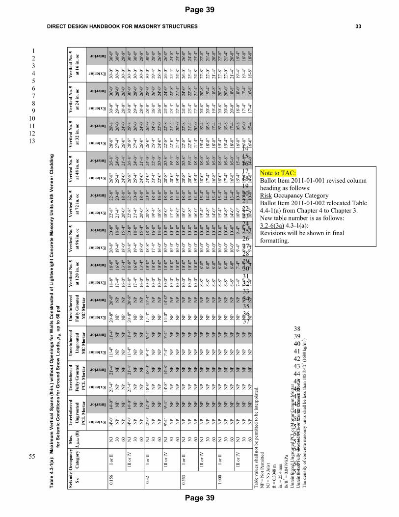
Note to TAC: Ballot Item 2011-01-001 revised column headings of each Table 3.2-6 as follows: Risk Occupancy Category Revisions will be shown in final formatting.
Note to TAC: Ballot Item 2011-01-001 revised column heading as follows: Risk Occupancy Category Ballot Item 2011-01-002 relocated Table 4.4-1(a) from Chapter 4 to Chapter 3. New table number is as follows: 3.2-6(3a) 4.3-1(a): Revisions will be shown in final formatting.
Note to TAC: Ballot Item 2011-01-001 revised column heading as follows: Risk Occupancy Category Ballot Item 2011-01-002 relocated Table 4.4-1(a) from Chapter 4 to Chapter 3. New table number is as follows: 3.2-6(3b) 4.3-1(b): Revisions will be shown in final formatting.
Note to TAC: Ballot Item 2011-01-001 revised column heading as follows: Risk Occupancy Category Ballot Item 2011-01-002 relocated Table 4.4-1(a) from Chapter 4 to Chapter 3. New table number is as follows: 3.2-6(4a) 4.4-1(a): Revisions will be shown in final formatting.
Note to TAC: Ballot Item 2011-01-001 revised column heading as follows: Risk Occupancy Category Ballot Item 2011-01-002 relocated Table 4.4-1(a) from Chapter 4 to Chapter 3. New table number is as follows: 3.2-6(4b) 4.4-1(b): Revisions will be shown in final formatting.
Page 42
Page 42
DIRECT DESIGN HANDBOOK FOR MASONRY STRUCTURES 37
1
Table 3.2-7: List of Lateral Force Coefficients Tables
Table values shall not be permitted to be interpolated.ft = 0.3048 min. = 25.4 mm
Vertical Reinforcement
Schedule
Horizontal Reinforcement
Schedule
Grouting Schedule k 1
k 2
Vertical Reinforcement
Schedule
Horizontal Reinforcement
Schedule
Grouting Schedule k 1
k 2
Vertical Reinforcement
Schedule
Horizontal Reinforcement
Schedule
Grouting Schedule k 1
k 2
Page 46
Page 46
DIRECT DESIGN HANDBOOK FOR MASONRY STRUCTURES 41
1
Table 3.2-8(10): Lateral Force Coefficients for Ordinary Reinforced Masonry Shear Walls Under any of the Following Conditions:
Condition 1: 150 (241 kph) < V < 160 mph (258 kph); 30 ft (9.1 m) < L joist < 60 ft (18.3 m); Interior Location
L seg=2'-0" L seg=2'-8" L seg=3'-4" L seg=4'-0" L seg=8'-0" L seg=12'-0" L seg=16'-0" L seg=20'-0" L seg=60'-0" L seg=100'-0" L seg=200'-0"
No. 5 at 120 in. BJR at 16 in. Partially 8,502 27,892 35,087 41,023 46,331 73,774 99,122 123,945 148,558 456,135 763,712 1,532,654 No. 5 at 96 in. BJR at 16 in. Partially 8,750 27,892 35,087 41,023 46,331 73,774 99,122 123,945 156,308 479,943 803,577 1,612,664 No. 5 at 72 in. BJR at 16 in. Partially 9,196 27,892 35,087 41,023 46,331 73,774 99,122 134,153 169,185 519,504 869,823 1,745,620
No. 5 at 48 in.
BJR at 16 in. or No. 5 at 48, 32,
or 24 in. Partially 10,088 27,892 35,087 41,023 46,331 73,774 114,113 154,453 194,792 598,184 1,001,575 2,010,055 No. 5 at 48 in. No. 5 at 16 in. Fully 22,680 27,892 35,087 41,023 46,331 73,774 114,113 154,453 194,792 598,184 1,001,575 2,010,055
No. 5 at 32 in.
BJR at 16 in. or No. 5 at 48, 32,
or 24 in. Partially 11,402 27,892 35,087 41,023 46,331 88,154 136,380 184,606 232,832 715,095 1,197,358 2,403,016 No. 5 at 32 in. No. 5 at 16 in. Fully 22,680 27,892 35,087 41,023 46,331 88,154 136,380 184,606 232,832 715,095 1,197,358 2,403,016
No. 5 at 24 in.
BJR at 16 in. or No. 5 at 48, 32,
or 24 in. Partially 12,160 27,892 35,087 41,023 46,331 102,355 158,380 214,405 270,430 830,678 1,390,926 2,791,545 No. 5 at 24 in. No. 5 at 16 in. Fully 22,680 27,892 35,087 41,023 46,331 102,355 158,380 214,405 270,430 830,678 1,390,926 2,791,545 No. 5 at 16 in. BJR at 16 in. Fully 17,765 27,892 35,087 46,979 58,872 130,228 201,584 272,940 344,296 1,057,855 1,771,414 3,555,312
No. 5 at 16 in.No. 5 at 48, 32,
24, or 16 in. Fully 22,680 27,892 35,087 46,979 58,872 130,228 201,584 272,940 344,296 1,057,855 1,771,414 3,555,312 Table values shall not be permitted to be interpolated.ft = 0.3048 min. = 25.4 mm
Table 3.2-8(11): Lateral Force Coefficients for Ordinary Reinforced Masonry Shear Walls Under any of the Following Conditions:
Condition 1: 160 (258 kph) < V < 180 mph (290 kph); 0 ft (0 m) < L joist < 30 ft (9.1 m); Interior Location
Condition 2: 160 (258 kph) < V < 180 mph (290 kph); 30 ft (9.1 m) < L joist < 60 ft (18.3 m); Exterior Location
L seg=2'-0" L seg=2'-8" L seg=3'-4" L seg=4'-0" L seg=8'-0" L seg=12'-0" L seg=16'-0" L seg=20'-0" L seg=60'-0" L seg=100'-0" L seg=200'-0"
No. 5 at 120 in. BJR at 16 in. Partially 7,372 25,418 31,168 35,660 39,523 58,299 74,979 91,135 107,082 328,740 550,398 1,104,544 No. 5 at 96 in. BJR at 16 in. Partially 7,511 25,418 31,168 35,660 39,523 58,299 74,979 91,135 114,926 352,830 590,734 1,185,495 No. 5 at 72 in. BJR at 16 in. Partially 7,762 25,418 31,168 35,660 39,523 58,299 74,979 101,469 127,960 392,862 657,765 1,320,021 No. 5 at 48 in. BJR at 16 in. Partially 8,264 25,418 31,168 35,660 39,523 58,299 90,159 122,020 153,880 472,484 791,087 1,587,596
No. 5 at 48 in.No. 5 at 48, 32,
or 24 in. Partially 10,088 25,418 31,168 35,660 39,523 58,299 90,159 122,020 153,880 472,484 791,087 1,587,596 No. 5 at 48 in. No. 5 at 16 in. Fully 22,680 25,418 31,168 35,660 39,523 58,299 90,159 122,020 153,880 472,484 791,087 1,587,596 No. 5 at 32 in. BJR at 16 in. Partially 9,003 25,418 31,168 35,660 39,523 72,867 112,708 152,550 192,392 590,808 989,224 1,985,265
No. 5 at 32 in.No. 5 at 48, 32,
or 24 in. Partially 11,402 25,418 31,168 35,660 39,523 72,867 112,708 152,550 192,392 590,808 989,224 1,985,265 No. 5 at 32 in. No. 5 at 16 in. Fully 22,680 25,418 31,168 35,660 39,523 72,867 112,708 152,550 192,392 590,808 989,224 1,985,265 No. 5 at 24 in. BJR at 16 in. Partially 9,742 25,418 31,168 35,660 39,523 87,257 134,991 182,726 230,460 707,803 1,185,146 2,378,503
No. 5 at 24 in.No. 5 at 48, 32,
or 24 in. Partially 12,716 25,418 31,168 35,660 39,523 87,257 134,991 182,726 230,460 707,803 1,185,146 2,378,503 No. 5 at 24 in. No. 5 at 16 in. Fully 22,680 25,418 31,168 35,660 39,523 87,257 134,991 182,726 230,460 707,803 1,185,146 2,378,503 No. 5 at 16 in. BJR at 16 in. Fully 15,347 25,418 31,168 41,710 52,252 115,506 178,760 242,014 305,267 937,805 1,570,343 3,151,688
No. 5 at 16 in.No. 5 at 48, 32,
24, 16 in. Fully 22,680 25,418 31,168 41,710 52,252 115,506 178,760 242,014 305,267 937,805 1,570,343 3,151,688 Table values shall not be permitted to be interpolated.ft = 0.3048 min. = 25.4 mm
Table 3.2-8(12): Lateral Force Coefficients for Ordinary Reinforced Masonry Shear Walls Under any of the Following Conditions:
Condition 1: 180 (290 kph) < V < 200 mph (322 kph); 0 ft (0 m) < L joist < 30 ft (9.1 m); Interior Location
Condition 2: 180 (290 kph) < V < 200 mph (322 kph); 30 ft (9.1 m) < L joist < 60 ft (18.3 m); Exterior Location
L seg=2'-0" L seg=2'-8" L seg=3'-4" L seg=4'-0" L seg=8'-0" L seg=12'-0" L seg=16'-0" L seg=20'-0" L seg=60'-0" L seg=100'-0" L seg=200'-0"
No. 5 at 120 in. BJR at 16 in. Partially 7,468 26,467 32,828 37,931 42,405 64,847 85,193 105,015 124,628 382,628 640,628 1,285,629 No. 5 at 96 in. BJR at 16 in. Partially 7,607 26,467 32,828 37,931 42,405 64,847 85,193 105,015 132,432 406,599 680,766 1,366,184 No. 5 at 72 in. BJR at 16 in. Partially 7,858 26,467 32,828 37,931 42,405 64,847 85,193 115,297 145,400 446,433 747,466 1,500,048 No. 5 at 48 in. BJR at 16 in. Partially 8,360 26,467 32,828 37,931 42,405 64,847 100,294 135,741 171,188 525,657 880,126 1,766,299
No. 5 at 48 in.No. 5 at 48, 32,
or 24 in. Partially 10,088 26,467 32,828 37,931 42,405 64,847 100,294 135,741 171,188 525,657 880,126 1,766,299 No. 5 at 48 in. No. 5 at 16 in. Fully 22,680 26,467 32,828 37,931 42,405 64,847 100,294 135,741 171,188 525,657 880,126 1,766,299 No. 5 at 32 in. BJR at 16 in. Partially 9,099 26,467 32,828 37,931 42,405 79,335 122,724 166,112 209,501 643,386 1,077,271 2,161,984
No. 5 at 32 in.No. 5 at 48, 32,
or 24 in. Partially 11,402 26,467 32,828 37,931 42,405 79,335 122,724 166,112 209,501 643,386 1,077,271 2,161,984 No. 5 at 32 in. No. 5 at 16 in. Fully 22,680 26,467 32,828 37,931 42,405 79,335 122,724 166,112 209,501 643,386 1,077,271 2,161,984 No. 5 at 24 in. BJR at 16 in. Partially 9,838 26,467 32,828 37,931 42,405 93,646 144,888 196,129 247,371 759,786 1,272,200 2,553,237
No. 5 at 24 in.No. 5 at 48, 32,
or 24 in. Partially 12,716 26,467 32,828 37,931 42,405 93,646 144,888 196,129 247,371 759,786 1,272,200 2,553,237 No. 5 at 24 in. No. 5 at 16 in. Fully 22,680 26,467 32,828 37,931 42,405 93,646 144,888 196,129 247,371 759,786 1,272,200 2,553,237 No. 5 at 16 in. BJR at 16 in. Fully 15,443 26,467 32,828 43,941 55,055 121,737 188,418 255,100 321,781 988,597 1,655,412 3,322,452
No. 5 at 16 in.No. 5 at 48, 32,
or 24 in. Fully 22,680 26,467 32,828 43,941 55,055 121,737 188,418 255,100 321,781 988,597 1,655,412 3,322,452 No. 5 at 16 in. No. 5 at 16 in. Fully 22,680 26,467 32,828 43,941 55,055 121,737 188,418 255,100 321,781 988,597 1,655,412 3,322,452
Table values shall not be permitted to be interpolated.ft = 0.3048 min. = 25.4 mm
k 1
k 1
k 1
Vertical Reinforcement
Schedule
Horizontal Reinforcement
Schedule
Grouting Schedule
k 2
Vertical Reinforcement
Schedule
Horizontal Reinforcement
Schedule
Grouting Schedule
k 2
Vertical Reinforcement
Schedule
Horizontal Reinforcement
Schedule
Grouting Schedule
k 2
Page 47
Page 47
42 DIRECT DESIGN HANDBOOK FOR MASONRY STRUCTURES
1
2 3 4 5 6 7 8 9 10 11 12 13 14 15 16 17 18 19 20
Table 3.2-8(13): Lateral Force Coefficients for Ordinary Reinforced Masonry Shear Walls Under any of the Following Conditions:
Condition 1: 160 (258 kph) < V < 180 mph (290 kph); 30 ft (9.1 m) < L joist < 60 ft (18.3 m); Interior Location
L seg=2'-0" L seg=2'-8" L seg=3'-4" L seg=4'-0" L seg=8'-0" L seg=12'-0" L seg=16'-0" L seg=20'-0" L seg=60'-0" L seg=100'-0" L seg=200'-0"
No. 5 at 120 in. BJR at 16 in. Partially 8,502 29,776 38,078 45,123 51,539 85,632 117,629 149,101 180,364 553,851 927,337 1,861,053 No. 5 at 96 in. BJR at 16 in. Partially 8,750 29,776 38,078 45,123 51,539 85,632 117,629 149,101 188,041 577,439 966,837 1,940,333 No. 5 at 72 in. BJR at 16 in. Partially 9,196 29,776 38,078 45,123 51,539 85,632 117,629 159,212 200,796 616,636 1,032,475 2,072,073
No. 5 at 48 in.
BJR at 16 in. or No. 5 at 48, 32,
or 24 in. Partially 10,088 29,776 38,078 45,123 51,539 85,632 132,474 179,317 226,160 694,585 1,163,011 2,334,075 No. 5 at 48 in. No. 5 at 16 in. Fully 22,680 29,776 38,078 45,123 51,539 85,632 132,474 179,317 226,160 694,585 1,163,011 2,334,075
No. 5 at 32 in.
BJR at 16 in. or No. 5 at 48, 32,
or 24 in. Partially 11,402 29,776 38,078 45,123 51,539 99,865 154,522 209,179 263,835 810,402 1,356,969 2,723,386 No. 5 at 32 in. No. 5 at 16 in. Fully 22,680 29,776 38,078 45,123 51,539 99,865 154,522 209,179 263,835 810,402 1,356,969 2,723,386 No. 5 at 24 in. BJR at 16 in. Partially 12,332 29,776 38,078 45,123 51,539 113,921 176,303 238,685 301,068 924,889 1,548,711 3,108,265
No. 5 at 24 in.No. 5 at 48, 32,
or 24 in. Partially 12,716 29,776 38,078 45,123 51,539 113,921 176,303 238,685 301,068 924,889 1,548,711 3,108,265 No. 5 at 24 in. No. 5 at 16 in. Fully 22,680 29,776 38,078 45,123 51,539 113,921 176,303 238,685 301,068 924,889 1,548,711 3,108,265 No. 5 at 16 in. BJR at 16 in. Fully 17,937 29,776 38,078 51,006 63,934 141,501 219,069 296,636 374,203 1,149,877 1,925,550 3,864,733
No. 5 at 16 in.No. 5 at 48, 32,
24, or 16 in. Fully 22,680 29,776 38,078 51,006 63,934 141,501 219,069 296,636 374,203 1,149,877 1,925,550 3,864,733 Table values shall not be permitted to be interpolated.ft = 0.3048 min. = 25.4 mm
Table 3.2-8(14): Lateral Force Coefficients for Ordinary Reinforced Masonry Shear Walls Under any of the Following Conditions:
Condition 1: 180 (290 kph) < V < 200 mph (322 kph); 30 ft (9.1 m) < L joist < 60 ft (18.3 m); Interior Location
L seg=2'-0" L seg=2'-8" L seg=3'-4" L seg=4'-0" L seg=8'-0" L seg=12'-0" L seg=16'-0" L seg=20'-0" L seg=60'-0" L seg=100'-0" L seg=200'-0"
No. 5 at 120 in. BJR at 16 in. Partially 8,502 31,790 41,287 49,526 57,136 98,393 137,554 176,191 214,618 659,113 1,103,608 2,214,846 No. 5 at 96 in. BJR at 16 in. Partially 8,750 31,790 41,287 49,526 57,136 98,393 137,554 176,191 222,216 682,464 1,142,712 2,293,332 No. 5 at 72 in. BJR at 16 in. Partially 9,196 31,790 41,287 49,526 57,136 98,393 137,554 186,197 234,839 721,263 1,207,688 2,423,748
No. 5 at 48 in.
BJR at 16 in. or No. 5 at 48, 32,
or 24 in. Partially 10,088 31,790 41,287 49,526 57,136 98,393 152,241 206,089 259,938 798,419 1,336,900 2,683,104 No. 5 at 48 in. No. 5 at 16 in. Fully 22,680 31,790 41,287 49,526 57,136 98,393 152,241 206,089 259,938 798,419 1,336,900 2,683,104
No. 5 at 32 in.
BJR at 16 in. or No. 5 at 48, 32,
or 24 in. Partially 11,402 31,790 41,287 49,526 57,136 112,468 174,050 235,633 297,216 913,045 1,528,873 3,068,444 No. 5 at 32 in. No. 5 at 16 in. Fully 22,680 31,790 41,287 49,526 57,136 112,468 174,050 235,633 297,216 913,045 1,528,873 3,068,444 No. 5 at 24 in. BJR at 16 in. Partially 12,523 31,790 41,287 49,526 57,136 126,365 195,594 264,823 334,052 1,026,341 1,718,631 3,449,354
No. 5 at 24 in.No. 5 at 48, 32,
or 24 in. Partially 12,716 31,790 41,287 49,526 57,136 126,365 195,594 264,823 334,052 1,026,341 1,718,631 3,449,354 No. 5 at 24 in. No. 5 at 16 in. Fully 22,680 31,790 41,287 49,526 57,136 126,365 195,594 264,823 334,052 1,026,341 1,718,631 3,449,354 No. 5 at 16 in. BJR at 16 in. Fully 18,128 31,790 41,287 55,330 69,372 153,627 237,883 322,138 406,393 1,248,946 2,091,499 4,197,882
No. 5 at 16 in.No. 5 at 48, 32,
24, or 16 in. Fully 22,680 31,790 41,287 55,330 69,372 153,627 237,883 322,138 406,393 1,248,946 2,091,499 4,197,882 Table values shall not be permitted to be interpolated.ft = 0.3048 min. = 25.4 mm
k 1
Vertical Reinforcement
Schedule
Horizontal Reinforcement
Schedule
Grouting Schedule
k 2
k 1
Vertical Reinforcement
Schedule
Horizontal Reinforcement
Schedule
Grouting Schedule
k 2
Page 48
Page 48
DIRECT DESIGN HANDBOOK FOR MASONRY STRUCTURES 43
1
Table 3.2-8(15): Lateral Force Coefficients for Special Reinforced Masonry Shear Walls Under any of the Following Conditions:
Condition 1: V < 200 mph (322 kph); L joist = 0 ft (0 m); Exterior Location
Condition 2: V < 200 mph (322 kph); L joist = 0 ft (0 m); Interior Location
L seg=2'-0" L seg=2'-8" L seg=3'-4" L seg=4'-0" L seg=8'-0" L seg=12'-0" L seg=16'-0" L seg=20'-0" L seg=60'-0" L seg=100'-0" L seg=200'-0"
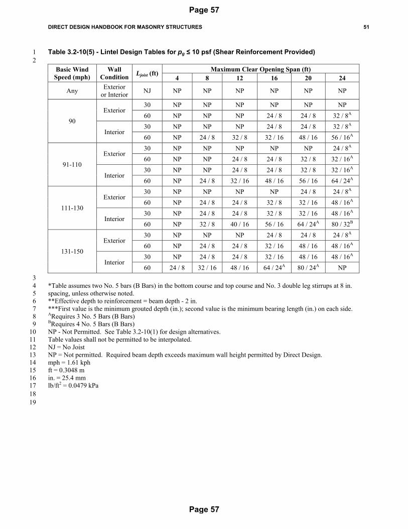
3 *Table assumes two No. 5 bars (B Bars) in the bottom course and top course, unless otherwise noted. 4 **Effective depth to reinforcement = beam depth - 2 in. 5 ***First value is the minimum grouted depth (in.); second value is the minimum bearing length (in.) on each side. 6 ARequires 3 No. 5 Bars (B Bars) 7 BRequires 4 No. 5 Bars (B Bars) 8 Table values shall not be permitted to be interpolated. 9 NJ = No Joist 10 mph = 1.61 kph 11 ft = 0.3048 m 12 in. = 25.4 mm 13 lb/ft2 = 0.0479 kPa 14 15 16 17 18 19 20 21 22 23 24 25 26 27 28 29 30
3 *Table assumes two No. 5 bars (B Bars) in the bottom course and top course, unless otherwise noted. 4 **Effective depth to reinforcement = beam depth - 2 in. 5 ***First value is the minimum grouted depth (in.); second value is the minimum bearing length (in.) on each side. 6 ARequires 3 No. 5 Bars (B Bars) 7 BRequires 4 No. 5 Bars (B Bars) 8 CRequires 5 No. 5 Bars (B Bars) 9 DRequires 6 No. 5 Bars (B Bars) 10 Table values shall not be permitted to be interpolated. 11 NJ = No Joist 12 NP = Not permitted. Required beam depth exceeds maximum wall height permitted by Direct Design. 13 mph = 1.61 kph 14 ft = 0.3048 m 15 in. = 25.4 mm 16 lb/ft2 = 0.0479 kPa 17 18 19 20 21 22 23 24 25
3 *Table assumes two No. 5 bars (B Bars) in the bottom course and top course, unless otherwise noted. 4 **Effective depth to reinforcement = beam depth - 2 in. 5 ***First value is the minimum grouted depth (in.); second value is the minimum bearing length (in.) on each side. 6 ARequires 3 No. 5 Bars (B Bars) 7 BRequires 4 No. 5 Bars (B Bars) 8 CRequires 5 No. 5 Bars (B Bars) 9 DRequires 6 No. 5 Bars (B Bars) 10 Table values shall not be permitted to be interpolated. 11 NJ = No Joist 12 NP = Not permitted. Required beam depth exceeds maximum wall height permitted by Direct Design. 13 mph = 1.61 kph 14 ft = 0.3048 m 15 in. = 25.4 mm 16 lb/ft2 = 0.0479 kPa 17 18 19 20 21 22
3 *Table assumes two No. 5 bars (B Bars) in the bottom course and top course and No. 3 double leg stirrups at 8 in. 4 spacing, unless otherwise noted. 5 **Effective depth to reinforcement = beam depth - 2 in. 6 ***First value is the minimum grouted depth (in.); second value is the minimum bearing length (in.) on each side. 7 ARequires 3 No. 5 Bars (B Bars) 8 BRequires 4 No. 5 Bars (B Bars) 9 NP - Not Permitted. See Table 3.2-10(1) for design alternatives. 10 Table values shall not be permitted to be interpolated. 11 NJ = No Joist 12 NP = Not permitted. Required beam depth exceeds maximum wall height permitted by Direct Design. 13 mph = 1.61 kph 14 ft = 0.3048 m 15 in. = 25.4 mm 16 lb/ft2 = 0.0479 kPa 17 18 19
3 *Table assumes two No. 5 bars (B Bars) in the bottom course and top course and No. 3 double leg stirrups at 8 in. 4 spacing, unless otherwise noted. 5 **Effective depth to reinforcement = beam depth - 2 in. 6 ***First value is the minimum grouted depth (in.); second value is the minimum bearing length (in.) on each side. 7 ARequires 3 No. 5 Bars (B Bars) 8 BRequires 4 No. 5 Bars (B Bars) 9 NP - Not Permitted. See Table 3.2-10(2) for design alternatives. 10 Table values shall not be permitted to be interpolated. 11 NJ = No Joist 12 NP = Not permitted. Required beam depth exceeds maximum wall height permitted by Direct Design. 13 mph = 1.61 kph 14 ft = 0.3048 m 15 in. = 25.4 mm 16 lb/ft2 = 0.0479 kPa 17 18 19 20
3 *Table assumes two No. 5 bars (B Bars) in the bottom course and top course and No. 3 double leg stirrups at 8 in. 4 spacing, unless otherwise noted. 5 **Effective depth to reinforcement = beam depth - 2 in. 6 ***First value is the minimum grouted depth (in.); second value is the minimum bearing length (in.) on each side. 7 ARequires 3 No. 5 Bars (B Bars) 8 BRequires 4 No. 5 Bars (B Bars) 9 NP - Not Permitted. See Table 3.2-10(3) for design alternatives. 10 Table values shall not be permitted to be interpolated. 11 NJ = No Joist 12 NP = Not permitted. Required beam depth exceeds maximum wall height permitted by Direct Design. 13 mph = 1.61 kph 14 ft = 0.3048 m 15 in. = 25.4 mm 16 lb/ft2 = 0.0479 kPa 17 18 19 20 21
3 *Table assumes two No. 5 bars (B Bars) in the bottom course and top course and No. 3 double leg stirrups at 8 in. 4 spacing, unless otherwise noted. 5 **Effective depth to reinforcement = beam depth - 2 in. 6 ***First value is the minimum grouted depth (in.); second value is the minimum bearing length (in.) on each side. 7 ARequires 3 No. 5 Bars (B Bars) 8 BRequires 4 No. 5 Bars (B Bars) 9 NP - Not Permitted. See Table 3.2-10(4) for design alternatives. 10 Table values shall not be permitted to be interpolated. 11 NJ = No Joist 12 NP = Not permitted. Required beam depth exceeds maximum wall height permitted by Direct Design. 13 mph = 1.61 kph 14 ft = 0.3048 m 15 in. = 25.4 mm 16 lb/ft2 = 0.0479 kPa 17 18 19 20 21 22 23 24 25 26 27 28 29 30
3 Project specifications for masonry designed in accordance with this Handbook shall meet or exceed the 4 requirements of the MSJC Specification. Design decisions required by the Mandatory Requirements 5 Checklist of the MSJC Specification that are applicable to masonry designed in accordance with this 6 Handbook include the following: 7 8 9
Specification Article
Description Design Requirement
1.4 A Compressive strength requirements
fm' = 1500 lb/in.2 (10.3 MPa)
1.4 Masonry Compressive Strength Verify compliance with fm'
1.6 Quality Assurance Define the submittal reporting and review procedure and specify the required level of quality assurance as defined in Tables 4 or 5 of the MSJC Specification based on the
building risk category
2.1 Mortar materials Mortar conforming to ASTM C270 Type S, cement-lime, mortar cement, or masonry cement as permitted by
Section 2.4.2
2.2 Grout Materials Verify grout meets the requirements of ASTM C476
2.3 Masonry unit materials Concrete masonry units complying with ASTM C90 and having a nominal thickness of
1 Figure 6.1-7 – Control Joint Detail at C Bar Locations 2
3 4
5
Page 70
Page 70
DIRECT DESIGN HANDBOOK FOR MASONRY STRUCTURES 65
1
2
3
4
5
6
This Page Intentionally Left Blank 7
Page 71
Page 71
Page 72
Page 72
COMMENTARY TO DIRECT DESIGN HANDBOOK FOR MASONRY STRUCTURES C-1
Commentary Chapter 1 1
General 2 3 C1.1 – Scope 4 5 This Handbook is written in mandatory language to permit adoption by reference in standards and codes. 6 The procedures in this Handbook were developed based on loading conditions as defined by ASCE 7 and 7 procedures defined by the strength design method of the MSJC Code. 8 9 Although the current edition of this Handbook is limited to single-story concrete masonry structures, 10 changes to future editions are contemplated to include a broader array of design variables and site 11 conditions. Some, but not all of the alternative design and construction variables currently under 12 consideration for future editions of this Handbook include: 13
Introduce the use of loadbearing clay masonry construction as an alternative to concrete masonry 14 construction. 15
Design of masonry elements having a nominal thickness other than 8 in. (203 mm). 16 Include reinforcement requirements using bars of different diameter. 17 Permit the use of Type N masonry mortar where permitted by the MSJC Code. 18 Introduce changes in roof elevations that are larger than those permitted by parapet heights. 19 Add options for multi-story construction. 20 Include design options that would permit roof overhangs. 21 Increase the maximum plan dimensions of diaphragms. 22 Incorporate options for using rigid diaphragms. 23 Introduce design options for using larger values of the specified compressive strength of masonry, 24
fm. 25 Permit non-shear wall elements (columns, piers, etc.) to be used to resist lateral forces. 26 Permit alternative loads, such as those resulting from mechanical systems, soil backfill, or 27
canopies. 28 Permit parapets heights greater than 4 ft (1.2 m). 29 Add design options for partially enclosed structures. 30
31 The direct design procedure is a table-based structural design method that permits the user, following a 32 specific series of steps, to design and specify relatively simple, single-story concrete masonry bearing-33 wall structures complying with the MSJC Code and Specification and ASCE 7. See Commentary Section 34 C2.3 for additional discussion on permitted load types and limitations. 35 36 The direct design procedure outlined herein embodies three principal phases: 37
In the first phase, the designer compiles information to be used later in the calculation of design 38 loads, including identification of loading requirements and critical loading combinations, and 39 identification of permissible shear wall types. 40 41
In the second phase, gravity and lateral loads are computed based on the information gathered in 42 the first phase and the spacing of each scheduled type of reinforcement is determined. 43 Computation of loads is based on the concept of flexible diaphragms, consistent with the 44 distribution of loads by tributary area. Computation of lateral loads is based on the concepts of 45 projected frontal area for wind loads, and projected frontal area plus diaphragm area for seismic 46 loads. Lateral loads are distributed along lines of lateral resistance, which must be selected by the 47 designer. Each designated line of resistance is composed of wall segments whose lengths are also 48 identified by the designer. These global steps, in effect, require the designer to designate 49 horizontal diaphragms, to specify how gravity loads are transferred from the diaphragms to 50
Page 73
Page 73
C-2 COMMENTARY TO DIRECT DESIGN HANDBOOK FOR MASONRY STRUCTURES
supporting walls, and to specify how lateral loads are transferred from the walls that are 1 perpendicular to the line of action to the in-plane lines of lateral load resistance. As necessary, 2 reinforcement is provided to resist in-plane and out-of-plane bending moments in vertically-3 spanning masonry strips due to gravity, wind, and earthquake loads; to resist gravity loads over 4 openings; to resist wind uplift; to resist out-of-plane loads on masonry above or under openings; 5 and to resist diaphragm chord forces. The remaining steps are identical to those that would be 6 followed in the conventional strength-based design of each scheduled type of reinforcement. 7 8
In the third phase, the designer details the required quantities and placement of reinforcement on 9 the project drawings, lists the information required by the MSJC Specification on the design 10 drawings; and prepares a project specification. Chapter 6 provides the minimum detailing 11 requirements for structures designed using the provisions of this Handbook. 12
13 The direct design procedure is primarily oriented toward reinforced masonry, but the procedure permits 14 unreinforced masonry if tension tie-downs (for example, threaded rods unbonded from the surrounding 15 masonry) are used to resist wind uplift. This requirement is necessary because the MSJC Code does not 16 permit unreinforced masonry to resist axial tensile stresses, which would likely be present under common 17 design scenarios covered by this Handbook. 18 19 The direct design approach originated with the members of the Veneer, Glass Block and Empirical 20 Subcommittee of the Masonry Standards Joint Committee (MSJC), who were in search of a design 21 approach that would be as simple to use and implement as the existing empirical design approach, but 22 without corresponding code-imposed limits. The resulting direct design method in this Handbook can be 23 used in virtually any seismic design category and design wind speed area, whereas the empirical design 24 method cannot. 25 26 27 C1.2 – Standards cited 28 29 Because the procedures of this Handbook are based upon the combined requirements of ASCE 7 and the 30 MSJC Code, users should verify that locally-adopted and enforced building code requirements are 31 consistent with the methodologies incorporated into this Handbook. As changes in the referenced 32 documents evolve, future editions of this Handbook are contemplated to correspond to each new edition 33 of ASCE 7 and the MSJC. 34 35 36 C1.3 – Definitions 37 38 For consistent application in this Handbook, terms that have particular meanings in the context of this 39 Handbook are defined. The definitions given are for the unique application in this Handbook and may not 40 correspond to ordinary usage. Glossaries of masonry terminology are available from several sources, 41 including: 42 43 Glossary of Concrete Masonry Terms, NCMA TEK 1-4, National Concrete Masonry Association, 44 Herndon, VA, 2004. 45 46 Glossary of Terms Relating to Brick Masonry, BIA Technical Notes 2, Brick Industry Association, 47 Reston, VA, January/February 1975 (Reissued March, 1999). 48 49 B Bars are located in the masonry lintel above openings. As illustrated in Figure C1.3-1, the header panel 50 above the opening is symmetrically reinforced with B Bars to accommodate uplift due to wind. For 51 clarity, no other reinforcing bars are shown in Figure C1.3-1. When B Bars and C Bars would be located 52
Page 74
Page 74
COMMENTARY TO DIRECT DESIGN HANDBOOK FOR MASONRY STRUCTURES C-3
in the same masonry course at the top of the header, the Handbook permits the use of C Bars alone to 1 resist uplift and diaphragm chord tension provided that the number of C Bars, required by Table 3.2-9, is 2 greater than or equal to the number of B Bars required by Table 3.2-10. The number of B Bars required 3 for a given opening, as determined in accordance with Table 3.2-10, depends upon the opening size, basic 4 wind speed, snow loads, joist span, and whether the opening is located in an exterior or interior wall. 5 6 Because the upper B Bars located at the diaphragm level are required only for uplift resistance due to 7 negative bending of the header panel, the portion of the masonry between the upper and lower B Bar 8 locations may not need to be grouted unless required by Table 3.2-10. For example, for the condition 9 shown in Figure C1.3-1, if Table 3.2-10 requires only the first two courses of masonry to be grouted then 10 the Handbook would require the top two courses to be similarly grouted and reinforced. In this example, 11 the course of masonry between the upper and lower two courses of masonry in the header panel would not 12 need to be grouted. 13 14 Vertical reinforcement in masonry structures designed in accordance with this Handbook consists of V 15 Bars, J Bars, and E Bars. The spacing of the V Bars (vertical bars) is determined in accordance with Table 16 3.2-5, 3.2-6, or 3.2-8, as appropriate, and can vary from 16 in. (406 mm) to 120 in. (3,048 mm). E Bars 17 (edge bars) are required at the edges of each masonry panel. Common examples of E Bars include vertical 18 bars located in cells adjacent to control joints or adjacent to openings. In accordance with the Handbook 19 provisions, where the spacing of the V Bars is such that the end vertical cell of a masonry panel contains a 20 V Bar, a single reinforcing bar satisfies the requirement for both the V Bar and E Bar, precluding the need 21 to provide two vertical reinforcing bars in a single cell. J Bars (jamb bars) are only required where the 22 location or size of an opening interrupts the placement of the V Bars. In such cases, J Bars are placed on 23 both sides of the opening in accordance with the provisions of this Handbook. The number of J Bars 24 required depends upon the number of V Bars displaced by the opening. 25 26
Page 75
Page 75
C-4 COMMENTARY TO DIRECT DESIGN HANDBOOK FOR MASONRY STRUCTURES
1 Figure C1.3-1 – B Bar Reinforcement 2
3 In the horizontal direction, H Bars are analogous to V Bars and O Bars are analogous to J Bars. B Bars 4 are analogous to E Bars but also serve to provide primary flexural reinforcement in lintels above openings 5 and at the top of a wall where wind uplift can result in the development of flexural tension in the 6 masonry. 7 8 Per Figure 6.1-5, C Bars are required to be continuous through control joints to maintain structural 9 continuity at diaphragm connection locations. Other reinforcing bars should be discontinued at control 10 joint locations in accordance with industry practices for crack controlC1.1, C 1.2. 11 12 13 14
Diaphragm level
Table 3.2-10
Page 76
Page 76
COMMENTARY TO DIRECT DESIGN HANDBOOK FOR MASONRY STRUCTURES C-5
C1.4 – Notations 1 2 Notations used in this Handbook are summarized in this section. Each symbol is unique, and where 3 possible, matches the notation used in other standards or reference documents. 4 5 The Commentary to this Handbook also introduces notations that are unique in context and undefined in 6 Section 1.4 of the Handbook. Definitions for these notations are as follows: 7 8 a = the width of the pressure coefficient zone used in determining wind pressures in accordance with 9
ASCE 7, ft (m). 10 Mn = nominal moment strength of a section, in.-lb (N-mm). 11 12 13 References 14 15 C1.1 NCMA TEK 10-2B, Control Joints for Concrete Masonry Walls – Empirical Method, National 16
Concrete Masonry Association, Herndon, VA, 2008. 17 C1.2 NCMA TEK 10-3, Control Joints for Concrete Masonry Walls – Alternative Engineered Method, 18
National Concrete Masonry Association, Herndon, VA, 2003. 19 20 21
22
Page 77
Page 77
C-6 COMMENTARY TO DIRECT DESIGN HANDBOOK FOR MASONRY STRUCTURES
Commentary Chapter 2 1
Limitations 2 3 Use of this Handbook is permitted if the limitations of Chapter 2 are satisfied. 4 5 Many common masonry design and construction conditions would not comply with the limitations 6 established by this Handbook. To maximize the use and flexibility of this design approach, portions of a 7 masonry structure may be designed using the engineering provisions presented in the legally adopted 8 building code, of which the MSJC Code forms a part, or for non-masonry materials, designed in 9 accordance with the legally adopted building code. This modification is permitted because the conditions 10 requiring strength and stiffness compatibility, a continuous load path, and the prohibition of transferring 11 loads into masonry designed in accordance with this Handbook. 12 13 An example of a common design condition where engineering analysis could be considered is the bearing 14 of a concentrated load from a transfer girder on a masonry wall. Under these conditions, the portion of 15 masonry subjected to this concentrated load would be designed using the provisions of the MSJC Code 16 while the remainder of the masonry structure could be designed using the procedures of this Handbook 17 provided the conditions of this section are met. 18 19 20 C2.1– Site Conditions 21 22
C2.1.1 Ground Snow Load – Permitting ground snow loads up to 60 lb/ft2 (2.9 kPa) is intended 23 to allow the use of this Handbook throughout most of the United States. Many 24 jurisdictions throughout the U.S. require the use of local snow load design values based 25 either on past experience or site-specific case studies. Such local criterion can be used 26 with this Handbook provided the upper limit of 60 lb/ft2 (2.9 kPa) is not exceeded. The 27 calculations performed in developing the Handbook tables are conservatively based on an 28 exposure factor of 1.2, a thermal factor of 1.2, an importance factor of 1.2, and a slope 29 factor of 1.0. 30
31 C2.1.2 Basic Wind Speed – The upper limit of 150 mph (241 kph) on the basic wind speed 32
effectively covers all U.S. States and Territories, except the Florida Keys, Guam, and 33 areas that are designated special wind regions where the basic wind speed exceeds 34 150 mph (241 kph). 35
36 C2.1.3 Exposure Category – The wind design loads in this Handbook were derived using wind 37
Exposure Category B and C site characteristics. The exposure category is a measure of 38 the surface roughness and topographical irregularities adjacent to a project site. This 39 Handbook cannot be used for projects located within Exposure Category D. ASCE 7 40 Commentary Section C26.7 provides additional information and background on exposure 41 categories and surface roughness. 42
43 44
Page 78
Page 78
COMMENTARY TO DIRECT DESIGN HANDBOOK FOR MASONRY STRUCTURES C-7
C2.1.4 Topography – The procedure in this Handbook is based on a Topographic Factor, Kzt, as 1 defined in ASCE 7, of 1.0. If the limitations of Section 2.1.4.1 are satisfied, the 2 Topographic Factor will be 1.0. Section 26.8 of ASCE 7 provides more exceptions that 3 may be considered in evaluating Kzt if the limitations of Section 2.1.4.1 are not satisfied. 4 Section 2.1.4.2 provides alternative methods of determining basic wind speeds for values 5 of Kzt greater than 1.0 when the conditions of Section 2.1.4.1 are not met. 6
7 Section 2.1.4.2 allows the provisions of this Handbook to be used to design buildings 8 where the regional topography adjacent to a project location results in wind speed-up 9 effects that must be accounted for in design. Table 2.1-1 provides basic wind speeds 10 modified by the Topographic Factor, Kzt, for use in the design tables presented in this 11 Handbook. The basic wind speed as modified by Kzt and presented in Table 2.1-1 cannot 12 exceed 150 mph (241 kph) as limited by Section 2.1.2 for use in this Handbook. The 13 modified values of the basic wind speed shown in Table 2.1-1 that exceed 150 mph (241 14 kph) are provided solely to aid the user in interpolating values of the modified basic wind 15 speed. 16
17 C2.1.5 No Commentary. 18 19 C2.1.6 No Commentary. 20 21 C2.1.7 Site Class – Section 20.1 of ASCE 7 states that “Where the soil properties are not known 22
in sufficient detail to determine the site class, Site Class D shall be used unless the 23 authority having jurisdiction or geotechnical data determine Site Class E or F soils are 24 present at the site.” This Handbook does not permit structures to be located on Site Class 25 E or F soils. 26
27 28
C2.2 – Architectural Conditions 29 30
C2.2.1 Number of Stories – This procedure is limited to the design of one-story, above-grade 31 structures. Floor loads, such as those created by a mezzanine, are not permitted. Because 32 Section 2.3.1 excludes soil loads, below-grade stories, including basements, are not 33 permitted to be designed using this procedure. 34
35 C2.2.2 Walls – The analysis and design used to develop the tables in this Handbook are based on 36
wall cross-sectional properties that are achieved when concrete masonry units having a 37 nominal thickness of 8 in. (203 mm) are used. Although the MSJC Code permits the use of 38 multi-wythe, composite construction that could result in the same nominal wall thickness 39 as the single-wythe construction, the section properties of composite masonry may differ 40 from a single-wythe assembly and are, therefore, not permitted. 41
42 C2.2.3 Height – The upper limit of 30 ft (9.1 m) on the total building height is driven by the wind 43
analysis procedures used in developing this Handbook. When the wall height is less than 44 4 ft (1.2 m), the shear-dominated performance of the wall may change, which in turn could 45 affect the values of k1 in Table 3.2-8. Therefore, a lower bound of 4 ft (1.2 m) was placed 46 on the wall height, which was considered a practical lower limit for building 47 configurations covered by this Handbook. The 4 ft (1.2 m) minimum does not apply to 48 segments of a wall, such as header or sill panels, which are permitted to be smaller than 4 49 ft (1.2 m). 50
51
Page 79
Page 79
C-8 COMMENTARY TO DIRECT DESIGN HANDBOOK FOR MASONRY STRUCTURES
C2.2.4 Parapets- The maximum permitted parapet height of 4 ft (1.2 m) is generally tall enough 1 to accommodate the roof slopes associated with buildings that would meet the limitations 2 of Chapter 2. A maximum height was necessary to limit the design snow load in the 3 calculations on which the procedure is based, because snow can drift and accumulate 4 against a parapet. In addition, as discussed in the Commentary in Section C27.6.2 of 5 ASCE 7, there can be higher out-of-plane wind loads on parapets than on the wall below 6 the diaphragm. Limiting the ratio of the parapet to the vertical span of the wall below the 7 roof diaphragm to 1:3 effectively permits more than twice the design out-of-plane wall 8 wind load and seismic load to occur at the parapet without exceeding the moment of the 9 wall below. The procedure in this Handbook assumes that the masonry acts as a simple 10 span from foundation to the roof diaphragm. For walls that support parapets meeting the 11 limitations of this section, the resulting loads and stresses induced in the support wall are 12 comparatively small relative to other controlling design loads. This finding is based on 13 analyses of various buildings incorporating parapets constrained by the limitations of the 14 direct design procedure. 15
16 C2.2.5 Wall Openings – The procedure in this Handbook does not account for multiple openings 17
that are stacked vertically. Such openings may interrupt the load path of masonry 18 segments, thereby potentially reducing the resistance to out-of-plane wind and seismic 19 loads. Therefore, this procedure does not permit vertically aligned or partially aligned 20 openings. To simplify the design assumptions, distribution of loads, and detailing 21 requirements around openings, this Handbook requires that control joints be provided on 22 both sides of an opening in a masonry wall. Providing control joints on both sides of an 23 opening isolates the panels above and below the opening so as not to inadvertently transfer 24 in-plane loads from designated shear wall segments to these portions of the masonry 25 system. 26
27 C2.2.6 Penetrations – Through-wall penetrations are common in virtually all buildings. Some 28
penetrations are relatively small and have negligible impact on the strength or 29 performance of the element in which they are located. Other, larger, penetrations can 30 impact the strength of an assembly. The provisions of Section 2.2.6 permit relatively 31 minor penetrations to be placed in masonry walls designed in accordance with this 32 Handbook provided that the penetrations, regardless of their size, do not interrupt the 33 reinforcement within the assembly as this could have significant impact on the strength of 34 the masonry. Penetrations not complying with these limitations would need to be analyzed 35 using the provisions of the MSJC Code for their impact on the strength of the assembly in 36 which they are located. 37
38 C2.2.7 Roof Diaphragms – Each rectangular roof diaphragm must be surrounded and supported 39
along each edge by masonry walls as illustrated in Figure C2.2-1 because the procedure in 40 this Handbook assigns chord forces to a bond beam in the masonry. Openings in the 41 supporting masonry wall are permitted provided the conditions of this Handbook are met. 42 Outside of stated limitations, this Handbook does not address diaphragm design. A 43 designated shear wall segment is required in both principal directions at each corner of 44 each diaphragm because the procedure in this Handbook assumes that the perpendicular 45 wall segment provides additional out-of-plane bracing and tension reinforcement. The 46 additional stiffening is sufficient such that the critical wall strip will be located beyond a 47 distance that is 2a from the corner, where a is defined by Figure 28.6-1 and Figure 30.5-1 48 of ASCE 7. The difference between end zone loads and interior zone loads is compared to 49 the difference in capacities between a corner wall system and a simple vertically spanning 50 wall strip. The value of 2a can be as large as 24 ft (7.3 m) depending on the height and the 51 plan dimensions of the building. Further, a designated shear wall segment can have a 52
Page 80
Page 80
COMMENTARY TO DIRECT DESIGN HANDBOOK FOR MASONRY STRUCTURES C-9
much smaller plan length than 2a. The procedure in this Handbook, however, requires that 1 segments with smaller plan lengths have more reinforcement for taller buildings and for 2 buildings with larger plan dimensions, which increases the required length. Theoretically, 3 a wall could have narrow openings with many small designated shear wall segments, 4 which may create a condition where the stiffening effect of the corner may not be enough 5 and the end load zones may govern. Considering the impracticality of these conditions, 6 however, this design assumption is deemed reasonable and appropriate because of the 7 conservatism of the procedure (e.g. pinned-pinned assumption) and the inherent 8 redundancy of masonry. 9
10 This Handbook does not address the design of connections. Transferring forces between 11
horizontal diaphragms and vertical walls is critical to the performance of the structure. 12 Anchors used to achieve this force transfer are required to be designed in accordance with 13 the MSJC Code. 14
15 16
17 Figure C2.2-1 – Shear Wall Layout at Corners 18
19 20
C2.2.8 Roof Slope – The required minimum roof slope is to assure the roof will drain water. 21 Chapter 8 of ASCE 7 outlines minimum design criteria for roof drainage. Because 22 different roofing systems shed snow in different ways, there is no single trigger for a 23 minimum roof slope that would shed snow off of a structure. When the ground snow load 24 exceeds 25 lb/ft2 (1.2 kPa), this Handbook requires that the roof be designed to shed 25 snow. In developing the design tables of this Handbook, this limit was felt necessary in 26 order to keep the design loads to a reasonable level for the broad range of ground snow 27 loads considered in this document. 28
29
Page 81
Page 81
C-10 COMMENTARY TO DIRECT DESIGN HANDBOOK FOR MASONRY STRUCTURES
ASCE 7 Section 7.6 requires that certain unbalanced snow load conditions be accounted 1 for when designing hip, gable, curved , multiple folded plate, sawtooth or barrel vault 2 roofs. The calculations performed when developing the direct design tables were based 3 on conservative uniform snow loads that accounted for snow drift with a Cs coefficient 4 equal to 1 on top of the balanced snow loads. These conservative uniform snow loads 5 were associated with a blanket of snow that is as high as the tallest parapet permitted by 6 the Handbook. Analysis determined that the peak snow load for unbalanced snow 7 conditions on curved, multiple folded plate, sawtooth, and barrel vault roofs is less than 8 or equal to the blanket load used in the calculations when the ground snow load is less 9 than 25 lb/ft2 (1.2 kPa). For hip and gable roofs, ASCE 7 Figure 7-5 requires that a 10 relatively narrow portion of the roof at the ridge be designed for a peak load that could 11 exceed the blanket load used in the calculations. However, calculations that considered 12 this condition were based on joists that were either 30 ft (9.1 m) or 60 ft (18.3 m) long 13 and the analysis determined that the overall load effect caused by snow on masonry 14 elements will be less than the load used in the calculations. 15
16 C2.2.9 Changes in Diaphragm Elevation – The maximum projection between adjacent roof 17
diaphragms is limited to the maximum permitted parapet height to account for snow drift, 18 which cannot exceed the height of the parapet. The procedure in this Handbook is based 19 on the maximum snow drift that can accumulate due to the full height of the maximum 20 permitted parapet height. The snow drift is assumed to act over the entire area of the roof 21 diaphragm assuming the minimum permitted slope. These conditions represent the 22 greatest snow load that would be imposed on the masonry system. 23
24 ASCE 7 Section 7.9 requires that sliding snow be accounted for in addition to the 25
balanced snow load if the roof is not slippery with a slope that is greater than 2:12, and if 26 the roof is slippery with a slope that is greater than 1/4:12. An example of a slippery roof 27 is a standing seam lightgage metal roof. Analysis determined that the provisions of this 28 Handbook are applicable when the horizontal distance between the eave of the upper roof 29 and the ridge of the upper roof is not greater than 42 ft (12.8 m) and the ground snow 30 load does not exceed 25 lb/ft2 (1.2 kPa). 31
32 C2.2.10 Joists – The tables provided in this Handbook cover three different joist span lengths: No 33
Joist (NJ), 30 ft (9.1 m), and 60 ft (18.3 m). The No Joist option corresponds to the case 34 of an interior or exterior wall wherein the joist does not impose axial load on the wall. 35 For reasons detailed in Commentary Section C3.1, linear interpolation (or extrapolation) 36 is not permitted for joist spans other than those explicitly listed. Therefore, designs must 37 be based on the larger tabulated joist span length, when actual joist spans are between 38 those listed. Limiting the tributary area supported by each joist ensures that the resulting 39 load applied to the masonry is relatively uniform in magnitude and distribution. 40
41 The requirement that masonry elements are not permitted to support reactions from 42
tributary areas greater than that supported by a single joist is to preclude the application 43 of loads from collector elements, such as joist girders, that would result in the application 44 of a load on the masonry that is not considered in this Handbook. 45
46 The analyses and modeling assumptions used in developing the provisions of this 47
Handbook are based on an assumption that the joists transmit a uniform load along the 48 plan length of the bearing walls. Considering the limitations of the design solutions 49 permitted by the Handbook, this design criterion can safely be applied to joists spaced up 50 to 6 feet (1.8 m) on center. In cases where this joist spacing is exceeded, the Handbook 51
Page 82
Page 82
COMMENTARY TO DIRECT DESIGN HANDBOOK FOR MASONRY STRUCTURES C-11
can still be used to perform preliminary designs; however, the final solution will need to 1 be checked using conventional structural analysis techniques. 2
3 C2.2.11 Roof Drainage – The requirements for roof drainage are only intended for roofs with low 4
slopes, which have overflow drains or scuppers. The value ds refers to the difference in 5 elevation from the top of the roofing material to the inlet elevation for an overflow drain 6 or the flow line of a scupper. The value dh refers to the hydraulic head above the inlet 7 elevation for an overflow drain or the flow line of a scupper. The hydraulic head must be 8 determined by a hydraulic analysis that accounts for local rainfall intensity-duration-9 frequency curves, the tributary area that flows into the overflow drain or scupper, and the 10 geometry of the drainage system. The hydraulic head can be reduced by increasing the 11 number and/or area of the drains. The procedure in this Handbook is based on a roof live 12 load of 20 lb/ft2 (1.0 kPa). 13
14 In the load combinations required by ASCE 7, the greatest of the roof live load, snow 15
load, and rain load will govern in combinations that include those loads. Therefore, the 16 rain load will not govern design if it is less than either the roof live load or the snow load. 17 Section 2.2.11 effectively limits the rain load to 20 lb/ft2 (1.0 kPa) when the roof slope is 18 at its minimum allowable and the joist span is at least 30 ft. The hydraulic pressure is 19 greater than 20 lb/ft2 (1.0 kPa) at the drain; but reduces radially from the drain due to the 20 slope in the roof and constant top elevation of the accumulated water. The design 21 assumption of a 30 ft (9.1 m) joist span is conservative for the three span options 22 permitted by this Handbook. 23
24 C2.2.12 Isolation of Features - The Handbook procedures for designing masonry walls do not 25
have a mechanism for considering the additional loads imposed by canopies, signs, or 26 overhangs that are connected to them. Consequently, such features are prohibited from 27 being connected to the masonry so as to impart loads. 28
29 The exceptions noted in Handbook Section 2.2.12 are intended to accommodate common 30
finishes such as vinyl siding, plank siding, signs, and small lights and similar fixtures that 31 are regularly attached to masonry walls. The wall finish projection is limited to 6 in. (152 32 mm) to minimize the magnitude of increase in wind load acting on the structure as a 33 result of increased projected area. The 3 lb/ft2 (0.14 kPa) wall finish weight limit is 34 established to keep the resulting out-of-plane seismic forces acting on the wall as a result 35 of increased dead load to a safe level. 36
37 C2.2.13 Simplified Wind Load Procedure Limitations – The procedure in this Handbook is based 38
on the Main Wind Force Resisting System Envelope Procedure, Part 1 of ASCE 7. That 39 procedure is based on assumptions stated in Chapter 28 of ASCE 7. A masonry structure 40 that satisfies all the other limitations of Chapter 2 will generally satisfy the ASCE 7 41 limitations as long as the building is classified as an enclosed building by Section 26.2 of 42 ASCE 7. That section states that a building is enclosed if it is not open and not partially 43 enclosed. Generally, a building is open if each exterior wall is more than 80% open and a 44 building is partially enclosed if one exterior wall has more open area than all the other 45 exterior walls combined. Openings are generally defined by ASCE 7 as holes that are 46 designed to be open during design winds. 47
48 C2.2.14 Veneers – A masonry veneer, whether anchored or adhered, would impart additional out-49
of-plane loads onto the structural wythe of masonry during a seismic event. Adhered 50 masonry veneer would additionally impart a vertical load onto the structural wythe of 51 masonry because the dead load of the adhered veneer would be supported by the masonry 52
Page 83
Page 83
C-12 COMMENTARY TO DIRECT DESIGN HANDBOOK FOR MASONRY STRUCTURES
backup. The 35 lb/ft2 (1.68 kPa) upper limit on the installed weight of the masonry 1 veneer is a practical limit intended to cover the majority of commonly used masonry 2 veneer systems. See Commentary Section 3.2, Step 5H for additional discussion. 3
4 5
C2.3 – Loading Conditions 6 7 Within the limitations established by Chapter 2, design of masonry in accordance with this Handbook 8 accounts for gravity loads and for lateral loads in each principal plan direction. 9 10
C2.3.1 Load Types – The procedure in this Handbook is based on the assumption that the 11 structure is not ice-sensitive, as defined in Section 10.2 of ASCE 7. A masonry structure 12 meeting the limitations in Chapter 2 would not be ice-sensitive by this definition. No 13 other load types are permitted on the masonry, including but not limited to floor dead 14 loads, floor live loads, hydrostatic pressure, soil loads, flood loads, or crane loads. 15
16 C2.3.2 Roof Dead Load – The Commentary for Chapter 3, Step 5D, provides assistance in 17
calculating the roof dead load. A minimum dead load value is provided because the 18 masonry must be designed to resist uplift due to wind. The procedure in this Handbook is 19 based on a 2 lb/ft2 (0.1 kPa) roof dead load when using load combinations in which dead 20 load counteracts uplift forces. This minimum roof dead load is further reduced by the 21 load factor in the considered load combination. The maximum dead load value was set at 22 30 lb/ft2 (1.4 kPa) because that is an upper bound on common roof dead load values used 23 by designers for typical flexible diaphragm structures. The combined limitations of the 24 maximum roof dead load and flexible diaphragm criterion precludes the use of many 25 concrete roof systems. 26
27 Users can verify that the actual roof dead loads do not exceed the permitted roof dead 28
loads using several different methods, even accounting for the presence of mechanical 29 rooftop equipment. Consider a simple span diaphragm measuring 20 ft (6.1 m) by 20 ft 30 (6.1 m) in plan. This Handbook designs the bearing walls of this structure for a 31 superimposed axial dead load of 40 lb/ft (584 N/m) and 600 lb/ft (8,756 N/m), 32 corresponding to the lower 2 lb/ft2 (0.1 kPa) and upper 30 lb/ft2 (1.4 kPa) roof dead load, 33 respectively. If the actual dead load of the roof was only 12 lb/ft2 (0.6 kPa), resulting in 34 an axial dead load on the bearing walls of 240 lb/ft (3,502 N/m), the weight and location 35 of the rooftop equipment would need to be limited in such a manner so that the axial dead 36 load contribution from the rooftop equipment does not exceed 360 lb/ft (5,254 N/m) at 37 any location. Note, however, that this analysis does not consider the vertical profile of 38 the rooftop equipment and the corresponding wind and snow drifting loads that may 39 result due to the presence of the rooftop equipment, which requires additional analysis. 40
41 C2.3.3 Roof Live Load – The upper limit of 20 lb/ft2 (1.0 kPa) for the roof live load is a practical 42
value for the majority of the types of buildings intended to be covered by this Handbook. 43 Because this Handbook only considers single story buildings, floor live loads are not 44 considered. 45
46 C2.3.4 Eccentricity of Roof Loads – Refer to Commentary Section 3.2, Step 5H for additional 47
discussion on permitted eccentricity of applied roof loads. Interior load-bearing walls are 48 designed to carry roof loads from both sides of the wall. The eccentricity of these applied 49 loads is permitted to vary up to 1.25 in. (31.8 mm) from the centroid of the wall cross-50 section, but the resultant of each eccentrically applied load is not permitted to be applied 51 to the same half of the wall cross-section. Doing so would result in bending moments 52
Page 84
Page 84
COMMENTARY TO DIRECT DESIGN HANDBOOK FOR MASONRY STRUCTURES C-13
(P-delta effects) that are cumulative, which was not accounted for in this Handbook. 1 Concentrically applied roof loads are permitted. 2
3 4
2.4 – Material and Construction Requirements 5 6
C2.4.1 Units – The procedure in this Handbook requires that all masonry components designed 7 using the direct design method be constructed of concrete masonry units having a 8 nominal thickness of 8 in. (203 mm). Clay masonry may not be designed using the 9 procedure in this Handbook because it has a lower design modulus of elasticity for a 10 given specified compressive strength compared to concrete masonry construction used in 11 developing this procedure. The lower modulus of elasticity would yield larger 12 deflections, which may create a condition that is not permitted by ASCE 7 and/or MSJC 13 Code. In addition, hollow clay masonry units commonly have a thinner face shell than the 14 minimum required for concrete units. Because a T-beam analysis based on the minimum 15 face shell thickness of concrete masonry units was performed to determine the bending 16 capacities of partially grouted walls, the values in this Handbook should not be used for 17 thinner face shells. For these reasons, masonry constructed of clay masonry units cannot 18 be designed using this Handbook. Although clay masonry typically has a higher 19 compressive strength than concrete masonry, several of the underlying modeling 20 assumptions that form the basis of the Handbook would be violated if clay masonry were 21 designed using the provisions of the Handbook. In the future, modifications are planned 22 for Chapter 4 of this Handbook to permit clay masonry construction to be designed by the 23 direct design process. 24
25 The procedures of Chapter 3 permit the use of lightweight, medium weight, and normal 26 weight concrete masonry units. 27
28 C2.4.2 Mortar – The procedure in this Handbook is based on the strength design method according 29
to Chapter 3 of the MSJC Code. Section 3.1.8.1.1 of the MSJC Code requires that the 30 specified compressive strength of masonry equal or exceed 1,500 lb/in.2 (10.3 MPa). 31 Concrete masonry units are commonly specified to comply with ASTM C90, including the 32 minimum unit compressive strength of 1,900 lb/in.2 (13.1 MPa). Chapter 5 of this Handbook 33 is philosophically consistent with this practice because it does not require the compressive 34 strength of the concrete masonry units to be higher than the minimum required by ASTM 35 C90. Article 1.4 B of the MSJC Specification permits verification of the specified 36 compressive strength of masonry (fm) by either the unit strength method, which is based on a 37 table that requires knowledge of the unit strength and mortar type, or the prism strength 38 method, which requires testing of masonry assemblages consisting of units, mortar, and grout 39 (if applicable) to verify conformance with the specified compressive strength of masonry 40 used in design assumptions. For relatively simple structures that do not need high strength 41 materials, such as those addressed through this procedure, the prism strength method is not as 42 commonly used as the unit strength method because the prism strength method requires 43 compressive strength testing, which increases the cost and complexity of this inspection task. 44 The combination of minimum material properties required by this Handbook ensure that the 45 minimum specified compressive strength of the masonry will be at least 1,500 lb/in.2 46 (10.3 MPa), which can be easily verified through the use of the unit strength method. 47
48 To achieve the required 1,500 lb/in.2 (10.3 MPa) specified compressive strength of masonry 49
using the unit strength method with the minimum 1,900 lb/in.2 (13.1 MPa) concrete unit 50 strength permitted by ASTM C90, Type M or S mortar is required. While a Type M mortar 51 could be used without any impact on the structural design provisions of this Handbook, Type 52
Page 85
Page 85
C-14 COMMENTARY TO DIRECT DESIGN HANDBOOK FOR MASONRY STRUCTURES
S mortar is more commonly used and generally more appropriate for masonry structures 1 covered by this Handbook. Type N mortar, conversely, cannot be used to construct structures 2 designed by the procedures of this Handbook because both the compressive strength of the 3 masonry and the mortar-to-unit bond strength (modulus of rupture values in accordance with 4 Table 3.1.8.2 of the MSJC Code) would be lower. For structures assigned to Seismic Design 5 Categories A, B, or C, any Type S masonry mortar can be used (i.e., masonry cement mortar, 6 cement-lime mortar, or mortar cement mortar). In accordance with the MSJC Code, however, 7 neither Type N nor masonry cement mortars are permitted to be used in Seismic Design 8 Categories D, E, or F. Because air-entrained cement-lime mortars exhibit a reduced bond 9 strength, which was not taken into account in establishing the tables of this Handbook, 10 cement-lime mortars are not permitted to contain entrained air when used in the construction 11 of structures assigned to Seismic Design Categories D, E, or F. 12
13 C2.4.3 Reinforcement – No. 5 (M#16), Grade 60 (420 MPa) reinforcing bars are commonly used in 14
modern reinforced masonry construction because they are readily available in most markets; 15 the lap splice length requirement is modest compared to larger-diameter reinforcement, which 16 facilitates and economizes the use of low-lift grouting procedures; and because they are small 17 enough that multiple layers can be conveniently placed in the cells of an 8 x 8 x 16 inch (203 18 x 203 x 406 mm) hollow concrete masonry unit with sufficient tolerance and coverage to 19 permit horizontal reinforcement and vertical reinforcement to pass each other. The procedure 20 in this Handbook requires all bars to be the same size for simplicity. Bars other than No. 5 21 (M# 16) are not permitted, except for shear reinforcement used in the construction of masonry 22 lintels, because there are many provisions in the MSJC Code that are satisfied by the tables in 23 the procedure without the user’s explicit notification. An example is the various prescriptive 24 minimum reinforcement requirements in the MSJC Code. Another example is the maximum 25 reinforcement limits imposed by the MSJC Code that a user might exceed if an alternative 26 reinforcing bar size with an equivalent or larger area were to be used. 27
28 C2.4.4 Grout – Either fine or coarse grout complying with the requirements of ASTM C476 is 29
permitted to be used. For practical and economical reasons, it is common practice to 30 solidly grout a masonry wall when the reinforcement is closely spaced, even if all of the 31 grouted cells do not contain reinforcement. If the spacing of either the vertical or 32 horizontal reinforcement is 16 in. (406 mm) on center, the procedures of this Handbook 33 assume a solid grouted cross-section, except where the horizontal reinforcement consists 34 of bed joint reinforcement only, in which case solid grouting is not required. Because the 35 cross-section is assumed to be solid grouted in these cases when determining the design 36 strengths of the masonry elements, it would not be appropriate or conservative to 37 construct the masonry as partially grouted even though reinforcement is not present in 38 each cell or bond beam. As required by the MSJC Code, cells containing reinforcement 39 must be grouted. 40
41 C2.4.5 Specifications – Chapter 5 outlines the minimum material, testing, inspection, and 42
construction requirements required by this Handbook. 43 44 C2.4.6 Details – Details presented in Chapter 6 address minimum structural stability and life 45
safety provisions as required by the MSJC and ASCE 7. Not all of these details are 46 applicable to every building designed by this Handbook. The user should select only 47 those details that are applicable to the structure being designed. Serviceability and 48 aesthetic criteria, including crack control and water penetration mitigation, are not 49 addressed by this Handbook. Recommended industry practices should be followed for 50 detailing the structure to prevent or minimize water infiltration and potential cracking. 51
52
Page 86
Page 86
COMMENTARY TO DIRECT DESIGN HANDBOOK FOR MASONRY STRUCTURES C-15
Section 2.2.5 of the Handbook requires control joints to be placed on both sides of 1 openings located in walls designed in accordance with this Handbook. This requirement 2 is necessary to be consistent with the modeling and load distribution assumptions 3 inherent in the direct design procedure. The Handbook does not require locating and 4 spacing control joints for crack control, which are covered by industry guidelinesC2.1, C2.2. 5 These industry guidelines also provide for options to increase the amount of horizontal 6 reinforcement to minimize or eliminate the need for control joints for crack control. 7 Because control joints are required on either side of openings in accordance with this 8 Handbook are tied to structural performance, as opposed to crack control, the control 9 joints required by this Handbook are required regardless of the amount of horizontal 10 reinforcement provided. This Handbook requirement does not apply to control joints that 11 may or may not be provided at locations that are not adjacent to openings. 12
13 14
References 15 16 C2.1 NCMA TEK 10-2B, Control Joints for Concrete Masonry Walls – Empirical Method, National 17
Concrete Masonry Association, Herndon, VA, 2008. 18 19 C2.2 NCMA TEK 10-3, Control Joints for Concrete Masonry Walls – Alternative Engineered Method, 20
National Concrete Masonry Association, Herndon, VA, 2003. 21 22 23 24
25
26
Page 87
Page 87
C-16 COMMENTARY TO DIRECT DESIGN HANDBOOK FOR MASONRY STRUCTURES
1
2
3
4
5
This Page Intentionally Left Blank 6
7
8
Page 88
Page 88
COMMENTARY TO DIRECT DESIGN HANDBOOK FOR MASONRY STRUCTURES C-17
Commentary Chapter 3 1
Procedure 2 3 C3.1 – General 4 5 The procedure in this Handbook is based on a comparison of factored design loads and design strengths in 6 accordance with Chapter 3 “Strength Design of Masonry” of the MSJC Code for the limiting envelope of 7 conditions associated with each value in each Table. Linear interpolation is not permitted unless 8 specifically stated as being permitted because there are many factors that cause a non-linear relationship 9 between values in the table; in addition, so as to have a practical number of options in each Table, the 10 limiting conditions are typically so different that a linear approximation is not valid. 11 12 This Handbook covers only the design of masonry walls meeting the limitations of Chapter 2. The design 13 of diaphragms, foundations, and other components critical to the performance of buildings is not covered 14 by this Handbook. 15 16 The reinforcement bar designations in Figure 3.1-1 represent the reinforcing bar designations defined in 17 Chapter 1. 18 19 A structure designed in accordance with this Handbook may not require every type of reinforcing bar 20 shown in Figure 3.1-1. For example, a structure where the diaphragm is connected to the top of the 21 masonry wall (no parapet is present) is not required to have T Bars, because the C Bars located in the top 22 course provide the necessary structural continuity that would otherwise be provided by T Bars at the top 23 of a parapet. Similarly, unless the tables of Chapter 3 require more than one reinforcing bar per cell or 24 course, only a single reinforcing bar is required. For example, if two B Bars are required in a lintel above 25 an opening, two B Bars must be provided in the top course of the same header panel. For the remaining 26 perimeter of the top masonry course exclusive of this header panel, however, only a single T Bar is 27 required (for cases where a parapet is present and no other openings in the masonry occur). Likewise, an 28 O Bar provided in a panel above or below an opening is not provided in addition to H Bars in the panel, 29 but in lieu of these horizontal reinforcing bars over the length of the panel. 30 31 As required by this Handbook and the MSJC Code, structural continuity must be maintained between the 32 application of load and the final point of resistance. For reinforcement, this is most commonly achieved 33 through lap splicing of the reinforcement. Chapter 6 provides standardized details for lap splicing that is 34 applicable to the design of structures in accordance with this Handbook. 35 36 Additional commentary discussion is provided for each type of reinforcing bar throughout Chapter 3 in 37 the corresponding section where it is addressed. 38 39 40 C3.2 – Direct Design Procedure 41 42 Commentary on Step 1 43 44 The information obtained in this Step is required for design. Both wind and seismic design criteria are 45 necessary because ASCE 7 requires that all buildings be designed for both wind and seismic loading 46 conditions, and meet all prescriptive seismic requirements even if seismic loads do not govern the design 47 of any elements. 48 49
Page 89
Page 89
C-18 COMMENTARY TO DIRECT DESIGN HANDBOOK FOR MASONRY STRUCTURES
The procedure in this Handbook is valid for any of the four Risk Categories listed in Table 1.5-1 of ASCE 7. 1 Where the Risk Category is not required for input in a design table in this Handbook, the content of the design 2 table is based on Risk Category IV, which requires the highest importance factors. 3 4 Commentary on Step 2 5 6 Creation of preliminary plans will be more efficient if based on experience with the procedure in this 7 Handbook. The procedure requires selection of options that affect architectural limitations. For example, a 8 preliminary floor plan with many large openings and many small shear wall segments may require so 9 much reinforcement that the segment lengths need to be increased to maintain the minimum spacing of 10 vertical reinforcement required. The procedure in this Handbook is designed so that users may quickly 11 learn the limitations relevant to a particular geographic region. 12 13 Commentary on Step 3 14 15 The Seismic Design Categories in Table 3.2-1 were determined in accordance with Sections 11.4 to 11.6 16 of ASCE 7 based upon the Site Class soil profile. The site soil is classified in accordance with Chapter 20 17 of ASCE 7 as Site Class A, B, C, or D, corresponding to hard rock, rock, very dense soil and soft rock, 18 and stiff soil, respectively. The direct design procedure is not permitted for Site Class E (soft clay) or Site 19 Class F (soils requiring site response analysis) soil profiles. Where applicable, accounting for the actual 20 soil conditions at the project location may reduce the Seismic Design Category and therefore increase the 21 economy of the structure. 22 23 Commentary on Step 4 24 25 The LFRS Options in Table 3.2-2 satisfy the provisions of Section 1.18 of the MSJC Code. The MSJC 26 Code permits other types of Lateral Force Resisting Systems, such as Intermediate Reinforced Masonry 27 Shear Walls. The three shear wall types included in this Handbook, however, are only a subset of the 28 shear wall types permitted by the MSJC Code. The limitation on the number of shear wall types 29 addressed by this Handbook is to minimize the number of Tables for Lateral Force Coefficients. The 30 lateral force-resisting system is selected in Step 5E. 31 32 Commentary on Step 5 33 34 The procedure in this Handbook is based on a flexible diaphragm analysis, which is appropriate for the 35 limitations of Chapter 2. Designation of rectangular roof diaphragms within the entire roof plan of a 36 building is a critical part of the process, and there is often more than one way to designate these 37 diaphragms. Refer to Figure C3.2-1 for an example roof plan. For this example, the walls are shown and 38 there is no change in diaphragm elevation at the interior wall. When considering a North-South wind and 39 seismic loading direction, one may wish to divide this example roof plan into two designated diaphragms. 40 As shown in Figure C3.2-2 a, however, the dimensions of the northern rectangle may not meet the 41 limitations of Section 2.1 of this Handbook, so it may be necessary to combine areas that are defined by 42 wall lines and designate their combined area as one diaphragm. In Figure C3.2-2 b, the North-South walls 43 (wall lines A and B) on each side of Diaphragm 1NS are lines of resistance that must have sufficient 44 designated shear wall segments as required by the procedure in this Handbook. When considering an 45 East-West wind and seismic loading direction, one may wish to divide this example roof plan into two 46 designated diaphragms, as shown in Figure C3.2-3 a. In this case, the interior wall (wall line G) is a line 47 of resistance for both diaphragms and must have sufficient designated shear wall segments for both 48 diaphragms combined as required by the procedure in this Handbook. The plan dimensions of Diaphragm 49 1EW are approximately 1:5, as defined by Section 2.1 of this Handbook, which is permitted because this 50 is much less than 4:1. Alternatively, one may wish to designate the entire roof as one diaphragm, as 51 shown in Figure C3.2-3 b. This is permitted; however, note that the interior wall (wall line F) must then 52
Page 90
Page 90
COMMENTARY TO DIRECT DESIGN HANDBOOK FOR MASONRY STRUCTURES C-19
Exced
Diaphragm
Load
b. Alternative
Diaph
Load
Wall Line G
be detailed as a non-participating wall. It is permitted for the diaphragm designations to be different for 1 the two principal plan directions because the walls parallel to the plan direction under consideration are 2 designed in Steps 5A through 5L. 3 4
Figure C3.2-2 – Examples of Designations for North-South Wind and Seismic Loading 28 29 30 31
32 33 34 35 36 37 38 39 40 41 42 43 44 45 46 47
Diaphragm 1NS
Load
Diaphragm
Wall Li
Load
b. Attempt #2
Non-Participating
Diaphragm 1EW
Diaphragm 1EW
a. Attempt
NorthWall Line A
Page 91
Page 91
C-20 COMMENTARY TO DIRECT DESIGN HANDBOOK FOR MASONRY STRUCTURES
1 2
Figure C3.2-3 – Examples of Designations for East-West Wind and Seismic Loading 3 Commentary on Steps 5A through 5C 4 5 The area of the building elevation is directly proportional to the cumulative length of shear wall 6 segments that will be required in later steps. (For additional guidance on calculating the projected 7 surface area of a building for wind loads, refer to Figure 28.6-1 of ASCE 7.) This area is to be 8 calculated separately for each designated rectangular roof diaphragm, for each principal direction of 9 loading. The total area is determined in Step 5A, even though a portion of the load applied to the 10 building elevations will be transferred directly into the foundation, because Table 3.2-3 incorporates a 11 0.667 area reduction factor for this purpose. The 0.667 coefficient accounts for the presence of a 12 parapet when determining design wind pressures. For a simply supported wall with no parapet, this 13 value would be 0.50. However, the maximum value of 0.667 occurs when a wall spans 12 ft (3.7 m) or 14 less and has the maximum parapet height permitted by Chapter 2. Table 3.2-3 is also based on the net 15 Main Wind Force Resisting System pressures from Section 27.4 of ASCE 7. The calculations assume 16 that the end zone pressures, which are greater than the interior zone pressures, would be applied over 17 40% of the area. In ASCE 7, the length of the end pressure coefficient zone (a) ranges up to 40% of the 18 total length. Table 3.2-3 incorporates the maximum adjustment factor for building height and exposure 19 () as defined in ASCE 7 that could occur, based on Exposure Category and the maximum permitted 20 height of 30 ft. Table 3.2-3 incorporates the wind importance factors associated with the Risk 21 Categories. In addition, the greatest load factor required for wind cases in all of the required load 22 combinations is 1.6. The values of Cw were therefore calculated by multiplying A times the 0.667 area 23 reduction factor times the weighted average MWFRS pressure from ASCE 7 times the importance 24 factor times the maximum that could occur times a 1.6 load factor and dividing the product by 2 since 25 there are two lines of resistance required for each roof diaphragm. 26 27 The calculation of the projected area, A, for determining the lateral wind force in each principle plan 28 direction is based on the full height of the building under consideration. Considering the building 29 elevations shown in Figure C3.2-4, the projected area, A, for each direction is calculated as follows: 30 For north-south elevations: A = (56 ft)(16.667 ft) = 933.3 ft2 31 For east-west elevations: A = (10 ft)(40 ft) + (20 ft)(6.667 ft) = 533.3 ft2 32 33 The values for A calculated above would in turn be multiplied by the appropriate Cw to determine the 34 factored lateral wind force, VLFRS-wind. 35 36
Page 92
Page 92
COMMENTARY TO DIRECT DESIGN HANDBOOK FOR MASONRY STRUCTURES C-21
1
2 3 4 5 6 7
Figure C3.2-4: Example Building Elevations 8 9
a. Attempt #1
Page 93
Page 93
C-22 COMMENTARY TO DIRECT DESIGN HANDBOOK FOR MASONRY STRUCTURES
Example calculation for Cw values provided in Table 3.2-3: 1 2 From Figure 28.6-1 of ASCE 7, the critical horizontal wind pressures applied to the walls for a 115 mph 3 (185 kph) basic wind speed are 29.0 lb/ft2 (1.39 kPa) for the end zone and 19.4 lb/ft2 (0.93 kPa) for the 4 interior zone. For these loading conditions and an Exposure Category B structure, the value for Cw is 5 calculated as follows: 6 7 Cw = [(0.6)(interior zone pressure) + (0.4)(end zone pressure)](area reduction factor)()/2 8 9 Cw = [(0.6)(19.4 lb/ft2) + (0.4)(29.0 lb/ft2)](0.667)(1)/2 = 7.8 lb/ft2 10 11 To convert from lb/ft2 to kPa, multiply by 0.0479. 12 13 14 Commentary on Step 5D 15 16 According to the requirements of Section 12.7.2 of ASCE 7, the effective seismic weight must include the 17 roof dead load, the portion of the wall dead loads that transfer to the roof diaphragm, the dead load of any 18 permanent equipment on the roof, and 20 percent of the uniform design snow load where the flat roof 19 snow load is greater than 30 lb/ft2 (1.4 kPa). 20 21 Table C3-1 and Table C3-2 in Chapter C3 of ASCE 7 provides the weights of many commonly used 22 building materials. One could use these tables to sum the weights of the dead loads to determine the roof 23 dead load in units of lb/ft2 (kPa). Generally speaking, a bar joist roof with metal deck and a built-up 24 minimum slope roof or a wood-framed roof with shingles on a pitch weighs approximately 10 to 15 lb/ft2 25 (0.48 to 0.72 kPa); however, it is common for a higher dead load to be used to account for future roofing 26 layers that may be added and for miscellaneous dead loads such as ceiling materials, ductwork, and lights. 27 It is not uncommon for a dead load of 20 or 25 lb/ft2 (0.96 to 1.20 kPa) to be used for such systems. 28 However, be aware that pre-engineered metal building roof systems can be extremely light. It is not 29 uncommon for a dead load of 2 lb/ft2 (0.10 kPa) to be used in the design of pre-engineered metal 30 buildings. It is possible for a masonry structure to have a Z-purlin and standing seam roof system with no 31 added dead loads for some applications such as storage buildings or warehouses. Note that such a roof 32 system would have to be through-fastened for it to be considered a simple diaphragm that meets the 33 limitations of Chapter 2. 34 35 It may be reasonable to assign 0.667 of the wall heights to the effective seismic weight, to account for the 36 effect of parapets as discussed in the Commentary above for calculating Cw. This should include all walls 37 that are attached to the diaphragm without a detail permitting slip in the direction under consideration. 38 Lightweight eight-inch (203 mm) concrete masonry walls, with the vertical grout patterns listed, generally 39 have weights shown in Table C3.2-1. Note that walls with a horizontal grouting pattern in addition to a 40 vertical pattern will have a higher dead load, determined by the weighted average of the two values. 41 Additional wall weights are available in NCMA TEK 14-13BC.3.1. 42 43
Page 94
Page 94
COMMENTARY TO DIRECT DESIGN HANDBOOK FOR MASONRY STRUCTURES C-23
Table C3.2-1 Dead Loads for Assemblies Constructed Using Lightweight Concrete Masonry Units. 1 2
Spacing of Vertical Reinforcement, in. (mm)
Wall Weight, lb/ft2 (kPa)
No grout 31 (1.5)
120 (3,048) 34 (1.6)
96 (2,438) 35 (1.7)
72 (1,829) 36 (1.7)
48 (1,219) 39 (1.9)
32 (813) 43 (2.1)
24 (610) 47 (2.3)
16 (406) 55 (2.6)
Fully grouted 78 (3.7)
3 4 The initial estimate of the seismic weight of the structure is based on an assumed spacing of the vertical 5 and horizontal reinforcement, which may change from this initial assumption in subsequent steps of the 6 direct design procedure. As one becomes more familiar with the direct design procedure, a more accurate 7 initial estimate of reinforcement spacing (and therefore seismic weight) can be obtained for a given set of 8 design variables. If there is uncertainty as to the quantity of required grout and reinforcement that may be 9 necessary for a particular design, an initial estimate can be obtained by determining the maximum 10 permitted spacing of the vertical reinforcement in accordance with Tables 3.2-5 and 3.2-6. 11 12 If the initially assumed seismic weight is less than that required by the resulting design, the design must 13 be rechecked to verify that the resulting seismic design forces can be safely resisted. 14 15 Generally speaking, the flat roof snow load can be more than 30 lb/ft2 (1.4 kPa) if the ground snow load is 16 greater than 25 lb/ft2 (1.2 kPa). The flat roof snow load can be calculated by Equation 7.3-1 of ASCE 7. 17 The procedure in this Handbook is based on the assumption that all factors in this formula are taken equal 18 to the maximum permitted values, which reduces this formula so that it is known that the flat roof snow 19 load cannot exceed 1.21 times the ground snow load. If one did not want to calculate Equation 7.3-1 of 20 ASCE 7, it would be conservative to assume the flat roof snow load is 1.21 times the ground snow load. 21 22 Commentary on Steps 5E through 5F 23 24 The values in Table 3.2-4 were determined by Section 12.8 of ASCE 7, according to the Equivalent 25 Lateral Force Method, using the importance factor corresponding to each Risk Category. The legally 26 adopted building code often requires that the seismic response modification coefficients, R, be shown on 27 the construction documents. 28 29 Commentary on Step 5G 30 31 In this step, the greater lateral load will govern design for that designated roof diaphragm in that direction 32 of consideration. 33 34 35
Page 95
Page 95
C-24 COMMENTARY TO DIRECT DESIGN HANDBOOK FOR MASONRY STRUCTURES
Commentary on Step 5H 1 2 This step provides the maximum permitted spacing of vertical reinforcement for wall strips with out-of-3 plane loading conditions. The selection of a permitted reinforcement schedule in accordance with this 4 Handbook is based on the design assumptions, models, and inherent conservatism outlined in these 5 provisions. Engineering analyses conducted in accordance with the provisions of the MSJC may result 6 in slightly different solutions as a result of differing assumptions or less conservatism than employed 7 by this Handbook. 8 9 Table 3.2-5 is based on a comprehensive load and resistance analysis incorporating the maximum loads 10 that could occur within the limitations of Chapter 2. Each wall is designed individually, running all the 11 load combinations in Section 2.3 of ASCE 7 and using the Strength Design method in Chapter 3 of the 12 MSJC Code. 13 14 In the analyses, both a dead load of 2 lb/ft2 (0.10 kPa) and a dead load of 30 lb/ft2 (1.4 kPa) were checked 15 for all load combinations. 16 17 In the analyses, the maximum possible snow load obtainable by Chapter 7 of ASCE 7 for each ground 18 snow load case was determined to be the following, including the effects of snow drift accumulation 19 against parapets. For a 0 lb/ft2 (0 kPa) ground snow load, 0 lb/ft2 (0 kPa) was used. For a 20 lb/ft2 20 (1.0 kPa) ground snow load, 52 lb/ft2 (2.5 kPa) was used. For a 40 lb/ft2 (1.9 kPa) ground snow load, 21 65 lb/ft2 (3.1 kPa) was used. For a 60 lb/ft2 (2.9 kPa) ground snow load, 76 lb/ft2 (3.6 kPa) was used. This 22 is conservative and should account for drift from roof top units as well. 23 24 In the analysis, as discussed in the Commentary of this Handbook for Section 2.2.6, the wind pressures 25 were determined using Chapters 28 and 30of ASCE 7. The following wind load scenarios were analyzed 26 for all load combinations: 27 28 Positive Components & Cladding Wind Load on the Roof 29 Negative Components & Cladding Wind Load on the Roof 30 Positive Components & Cladding Wind Load on the Wall 31 Negative Components & Cladding Wind Load on the Wall 32 Positive Main Wind Force Resisting System Wind Load on the Roof and Wall 33 Negative Main Wind Force Resisting System Wind Load on the Roof and Wall 34 35 For the Main Wind Force Resisting System wind pressures on the walls, 85% of the net pressures were 36 assumed to be positive pressures and 70% of the net pressures were assumed to be negative pressures. 37 This was based on the coefficients permitted in the Analytical Method of ASCE 7 because the Simplified 38 Method Tables in ASCE 7 provide net pressures, not MWFRS pressures on individual walls. 39 40 For wind design, interior pressures of 5 lb/ft2 (0.24 kPa) for up to 90 mph (145 kph) wind speed, 41 6 lb/ft2 (0.29 kPa) for up to 110 mph (177 kph) wind speed, 7 lb/ft2 (0.34 kPa) for up to 130 mph 42 (209 kph) wind speed, and 8 lb/ft2 (0.38 kPa) for up to 150 mph (241 kph) wind speed were used for 43 out-of-plane loads on interior walls. These pressures were compared to the out-of-plane seismic forces 44 generated as a function of the weight of the wall, with the controlling load selected for determining the 45 spacing of the vertical reinforcement. 46 47 For exterior walls, it was assumed there is a joist on one side of the wall only. For all analyses, it was 48 assumed that the axial loads of exterior walls were applied at an eccentricity of 1.25 in. (31.8 mm) toward 49 the interior from the centerline of the wall. 50 51
Page 96
Page 96
COMMENTARY TO DIRECT DESIGN HANDBOOK FOR MASONRY STRUCTURES C-25
For interior walls, it was assumed there is a joist bearing on both sides of the wall. Although this may be 1 conservative in some cases, it is intended to capture the majority of typical applications. To accomplish 2 this, for all analyses, it was assumed that the full axial load associated with joists on both sides of the wall 3 was applied but at an eccentricity of 0.625 in. (15.9 mm) to one side, which is half the exterior wall 4 eccentricity. This models the moment associated with half the axial load applied at the full eccentricity, 5 which could occur. 6 7 In reinforced masonry, the masonry must span horizontally to transfer loads to the vertical bars. The 8 Direct Design procedure is based on an arch model, commonly referred to as arching action. The model is 9 supported by researchC3.2. This model complies with the Strength Design provisions of the MSJC and 10 applies universally to vertical bars at any spacing, including bars greater than and less than six times the 11 nominal wall thickness, and is described below. 12 13 In walls with vertical reinforcement resisting out-of-plane loads, for a free body diagram of a horizontal 14 section of masonry that is as wide as the spacing of the vertical bars, with a vertical bar at the center, 15 internal stresses are required to resist any unbalanced loading condition for there to be static equilibrium. 16 An example of an unbalanced loading condition can occur at the jamb of a cased opening with no door, 17 where there is masonry on only one side of the vertical bar. The masonry must be able to safely resist 18 these internal stresses or the masonry would fail, causing the masonry to blow in between the vertical 19 bars. This is not a commonly observed phenomenon. However, many designers limit the spacing of 20 vertical reinforcement to six times the nominal wall thickness. For normal structures, it appears that it 21 would be difficult for there to be sufficient horizontal pressure to cause a blow in failure with bars that 22 close. Nonetheless, it is theoretically possible for a wall with sufficiently high out-of-plane pressures to 23 fail in horizontal load transfer with vertical bars at six times the nominal wall thickness, before the 24 vertical strips of masonry would fail. Therefore, masonry design should be based on a reliable mechanism 25 of transferring loads horizontally to the vertical bars in the masonry. 26 27 The above mechanism must occur regardless of the spacing of the vertical bars. In addition, there is no limit on 28 bar spacing for walls in Chapter 3 of the MSJC Code. (The limit of Section 1.9.6 pertains to the compressive 29 width per bar due to shear lag.) Therefore, design for this mechanism can and should be universal for any 30 vertical bar spacing imaginable, including more and less than six times the nominal wall thickness. 31 32 This mechanism cannot be modeled using reinforced masonry that incorporates bed joint reinforcement 33 because the minimum yield strength of the wires required by the mandatory ASTM’s referenced by the 34 MSJC Specification exceeds the permitted specified yield strength for reinforcement according to MSJC 35 Section 3.1.8.3. 36 37 In masonry with vertical bars and no bed joint reinforcement, it has been observed that the masonry will be 38 able to resist some out-of-plane pressure horizontally spanning as an unreinforced element until a vertical 39 crack forms halfway between the vertical bars and an arch is formed. The arch creates an in-plane thrust. 40 The thrust is either resisted by an opposing thrust from a continuous masonry wall, or at discontinuous ends 41 it is resisted by the section of masonry between the vertical crack and the end of the wall acting in-plane as a 42 beam which transfers this load to horizontal tie beams which resist this horizontal tension. 43 44 The MSJC Code Section 3.2.1.3 states that “Unreinforced (plain) masonry members shall be designed to 45 remain uncracked.” A strict interpretation of this provision prohibits designing masonry as reinforced 46 masonry to resist loads in one direction and then as unreinforced masonry to resist loads in another 47 direction. Because vertical bars are required to resist out-of-plane bending or axial tension, the Direct 48 Design procedure is based upon a reinforced masonry design model. In cases where reinforcement is 49 required in only one direction (either horizontal or vertical) the masonry spanning in the perpendicular 50 direction is designed as an arch in accordance with the design requirements of Section 3.3 (strength 51 design of reinforced masonry) in the MSJC Code. 52
Page 97
Page 97
C-26 COMMENTARY TO DIRECT DESIGN HANDBOOK FOR MASONRY STRUCTURES
The MSJC Code Section 3.3.1 states that Section 3.3 “Reinforced Masonry” applies to “masonry design 1 in which reinforcement is used to resist tensile forces”. Because masonry is not relied upon to resist any 2 tension in the arch model and all tension is resisted by reinforcement through the vertical bars resisting in-3 plane thrust and the horizontal bars acting as tie beams, there is no reason that the arched model cannot be 4 classified as reinforced masonry and the provisions of MSJC Section 3.3 applied to the model. Further, 5 there is no prohibition on such a model in the MSJC. 6 7 The strict interpretation referenced above also can be applied to shear walls. Therefore, for Direct Design, 8 shear walls with any vertical reinforcement for structural purposes should be designed as reinforced 9 masonry when resisting in-plane forces. The Direct Design procedure provides three LFRS Options 10 (Ordinary Unreinforced Masonry Shear Walls, Ordinary Reinforced Masonry Shear Walls, and Specially 11 Reinforced Shear Walls). Therefore, for walls with V bars, it can be assumed that there is at least one No. 12 5 (M#16) horizontal bar at 10 ft (3.0 m) on center, which is the minimum prescriptive horizontal 13 reinforcement for Ordinary Reinforced Shear Walls. These H bars can be relied on to act as tension tie 14 bars in the arch model of the mechanism, without adding any cost to the structure and permitting bars 15 spaced further than 48 in. (1,219 mm). 16 17 Due to the numerous discontinuous conditions that will occur in real buildings, it is conservative and is a 18 simplification to assume that all panels are discontinuous with respect to arching action loads, which 19 creates the most tension in both V and H bars for that case, but continuous for out-of-plane and axial 20 loading. Therefore the following interaction equation is appropriate for Direct Design: 21 22 (Moment due to out-of-plane and axial) / (Mn out-of-plane) 23 24 + (Moment due to in-plane-thrust) / (Mn in-plane-thrust) 1.0. 25 26 In the analysis, the tallest height was determined for the reinforced wall systems that satisfied the 27 following 16 conditions. 28 29 Condition No. 1: The ratio of factored load to gross area, not the net area, is required by Section 3.3.5.3 of 30 the MSJC Code to be less than 20% of the specified compressive strength of masonry, which as discussed 31 in the Commentary for Section 2.4.2 was assumed to be 1500 lb/in.2 (10.3 MPa). 32 33 Condition No. 2: The ratio of factored load to net area is required by Section 3.3.5.3 of the MSJC Code to 34 be less than 5% of the specified compressive strength of masonry. 35 36 Condition No. 3: The factored axial load is required by MSJC Section 3.3.4.1.1 to be less than the 37 nominal strength times a phi factor of 0.9. 38 39 Condition No. 4: The factored axial load and moment at the top of the wall are required to be within the 40 permitted curve on a nominal moment-axial load capacity interaction diagram. This includes a tension 41 check as well as compression check. 42 43 Condition No. 5: The factored axial load and moment at the middle of the wall, ignoring P-delta effects, 44 are required to be within the permitted curve on a nominal moment-axial load capacity interaction 45 diagram, accounting for phi. 46 47 Condition No. 6: A P-delta analysis was performed with 10 iterations because the factored moment at the 48 middle of the wall is required by Section 3.3.5 of the MSJC Code to be less than the nominal moment 49 capacity times phi. 50 51 Condition No. 7: The out-of-plane deflection under service loads was determined based on service loads 52 instead of factored loads by another P-delta analysis with 10 iterations because the service deflection is 53 required by Section 3.3.5.5 of the MSJC Code to be less than 0.007 times the vertical span of the wall. 54
55
Page 98
Page 98
COMMENTARY TO DIRECT DESIGN HANDBOOK FOR MASONRY STRUCTURES C-27
Condition No. 8: The out-of-plane deflection under service load from the previous condition was also 1 checked for cases with components and cladding wind loads to be less than 0.006 times the vertical span 2 of the wall because Section 1604.3.1 of the IBCC3.3 requires that the out-of-plane deflection of such walls 3 be limited to the vertical span divided by 240. Footnote f to Table 1604.3, referenced by Section 1604.3.1 4 of the IBC permits determining the deflection by the components and cladding wind load times a 0.7 5 reduction factor. 1/240 further divided by 0.7 equals 0.006. 6 7 Condition No. 9: The factored shear at the top of the wall is required by MSJC Code Section 3.3.4.1.2.1 8 to be less than the nominal shear strength times a phi factor of 0.8. Note that the shear was checked at the 9 top of the wall because there is less axial load, and less axial load will be associated with less nominal 10 shear capacity. Note also that the value for Pu in Equation 3-23 was included regardless of whether this 11 load was downward or upward (due to wind uplift). Also note that Mu/(Vudv) in that same equation was 12 taken as 1.0 as permitted by that section of the MSJC. 13 14 Condition No. 10: The area of reinforcement was compared to the maximum area of reinforcement 15 permitted by Section 3.3.3.5.1 of the MSJC Code, which is also required for out-of-plane wall design by 16 3.3.3.5.2, 3.3.3.5.3, and 3.3.3.5.4. The lambda values for wind pressures in Exposure C Categories vary 17 depending on building height according to Figure 28.6-1 and Figure 30.5-1 of ASCE 7. The above 18 analyses were performed for each wall assuming they span 30 ft (9.1 m). Then, if the maximum span 19 permitted was less than 30 ft (9.1 m), the analyses were re-performed with the value associated with a 20 building height equal to the maximum span permitted by the analysis. This process was based on the 21 assumption that the bottom of the wall is at or very near the ground level. Structures where this is not the 22 case, such as structures that are significantly elevated, should be evaluated independently. 23 24 Condition No. 11: For arching action between vertical bars, the tension was checked in the tie bars, 25 assuming there is just one No. 5 (M#16) taking 10 ft (3.0 m) of tributary in-place thrust reaction, and 26 assuming there are two discontinuous ends on each side of a panel that is as wide as the bar spacing, 27 which represents a worst case scenario that could occur under the limitations and assumptions upon which 28 this method is based. 29 30 Condition No. 12: For arching action, arch crushing of the masonry was checked. 31 32 Condition No. 13: With arching action taken into account, the tension in the vertical bars under biaxial 33 bending and eccentric axial loading was checked using the conservative and simplifying interaction 34 equation above. 35 36 Condition No. 14: The stability of the arch was checked to prevent snap-through buckling. 37 38 Condition No. 15: The out-of-plane deflection of the horizontal span (the flat arch) was compared to the 39 0.007 times the horizontal span. This is similar to the vertical span deflection check above. 40 41 Condition No. 16: The out-of-plane deflection of the horizontal span (the flat arch) resulting from a 42 components and cladding wind load was compared the serviceability check of 0.007 times the horizontal 43 span. This is similar to the vertical span deflection check above. 44 45 The values in Table 3.2-6 were determined by a similar procedure. Table 3.2-6(1) applies to walls 46 constructed of lightweight concrete masonry units. Table 3.2-6(2) applies to walls constructed of medium 47 weight or normal weight concrete masonry units. In accordance with ASTM C90, lightweight concrete 48 masonry units are required to have a density less than 105 lb/ft3 (1680 kg/m3). In order to establish an 49 upper limit on unit density for use with Table 3.2-6(2), units are not permitted to have a density in excess 50 of 135 lb/ft3 (2162 kg/m3) when used to construct masonry designed in accordance with this Handbook. 51 52
Page 99
Page 99
C-28 COMMENTARY TO DIRECT DESIGN HANDBOOK FOR MASONRY STRUCTURES
The increased weight of medium weight and normal weight concrete masonry units compared to 1 lightweight concrete masonry units increases the corresponding out-of-plane loading due to seismic 2 response. These larger seismic loads are accounted for in the permitted wall heights and reinforcement 3 schedules provided in Table 3.2-6. Although the increased dead load of walls constructed of medium 4 weight and normal weight concrete masonry units could be used to offset wind uplift and overturning 5 effects, such modeling is conservatively neglected in this modification to the direct design method. The 6 permitted wall heights of Table 3.2-6.b were determined by increasing the installed weight of the masonry 7 wall by 8 lb/ft2 (0.38 kPa) over the corresponding lightweight concrete masonry unit wall weight. This 8 increase in wall weight corresponds to a unit density of 135 lb/ft3 (2162 kg/m3), which captures the 9 majority of normal weight concrete masonry units and can be conservatively applied to any medium 10 weight concrete masonry unit. 11 12 Commentary on Step 5I 13 14 In this Handbook, a designated shear wall segment is defined as a portion of wall that is continuous in 15 plan and uninterrupted from the foundation to the diaphragm elevation. A designated shear wall segment 16 cannot contain an opening, a control joint, an expansion joint, or a construction joint. Because designated 17 shear wall segments with shorter plan lengths typically require more reinforcement, it may be more 18 economical to treat short wall segments as non-designated shear walls or as non-participating walls, rather 19 than as designated shear wall segments. 20 21 The values of k1 and k2 depend on Lseg , the selected LFRS Option, and the spacing of the horizontal and 22 vertical reinforcement. The wall reinforcement schedule requires that the designer specify the spacing of 23 the V Bars, SV . 24 25 The wall reinforcement schedule requires that the designer specify the spacing of the H Bars, SH , and the 26 grouting schedule. Walls with either vertical or horizontal bars spaced at 16 in. (406 mm) or less are 27 assumed to be fully grouted. Walls with reinforcement at a greater spacing are assumed to be partially 28 grouted. In some cases, a lower value of SH may increase the values of k1 and k2 . 29 30 Lreq decreases as the resistance coefficients increase. If the sum of the plan lengths of designated shear wall 31 segments on each line of resistance is less than Lreq , either select a smaller SV than the one selected in Step 32 5I.3, or select an LFRS Option with more prescriptive reinforcement than the one chosen in Step 5E, or 33 revise the preliminary floor plan created in Step 2, and redo the procedure from the earliest revised Step. 34 35 The in-plane design of masonry shear walls is provided for in Table set H. Three different groups are 36 provided, each inherently complying with the minimum prescriptive reinforcement, design, and detailing 37 requirements for Ordinary Plain (Unreinforced) Masonry Shear Walls, Ordinary Reinforced Masonry 38 Shear Walls, and Special Reinforced Masonry Shear Walls per the provisions of the MSJC Code. As 39 such, detailing options that may be permitted, for example for Ordinary Plain Reinforced Masonry Shear 40 Walls, may not be permitted for Special Reinforced Masonry Shear Walls and so on. 41 42 The design coefficients k1 and k2 are based on the limiting shear and flexural strength, respectively, per 43 the strength design requirements of the MSJC for the wall configuration and reinforcement detailing 44 listed. Based upon the critical design shear load for each wall configuration, the inelastic story drift 45 (elastic deformation multiplied by the appropriate Cd value) is also checked for each wall configuration. 46 In all cases, the permitted deflection is limited to 1 percent of the wall height. Further, in the case of the 47 reinforced shear walls, the maximum tensile reinforcement limits are also checked. Only those walls 48 configurations that provide a k1 and k2 value meet all of the strength design requirements per the MSJC 49 Code. Shear wall design coefficients listed as not permitted (NP) in Table 3.2-8 either exceed the 50 permitted strength of the wall segment, exceed the in-plane deflection permitted by the MSJC Code or 51 ASCE 7, or exceed the permitted maximum flexural tension reinforcement values allowed by the MSJC 52
Page 100
Page 100
COMMENTARY TO DIRECT DESIGN HANDBOOK FOR MASONRY STRUCTURES C-29
Code for the specific design conditions considered by each table. The units for k1 are force per unit length 1 because the value for k1 must be multiplied by the wall height to obtain a shear wall segment length 2 design strength. The units for k2, which are not multiplied by wall height, are force. 3 4 For simplicity, the factored shear force, Vu, is limited to 40 percent of the nominal shear strength, Vn, for 5 shear critical special reinforced masonry shear walls to meet the requirements of Section 1.18.3.2.6.1.1 of 6 the MSJC Code. Likewise, for flexurally dominated special reinforced masonry shear walls, the limiting 7 design shear strength, Vn, is checked against the shear corresponding to the development of 125 percent 8 of the nominal flexural strength. Limiting the design shear strengths based on these criterion is 9 conservative. More economical designs can be achieved through a more rigorous analysis taking into 10 account specific design requirements. 11 12 Note that Section 3.2.1.3 of the MSJC Code requires that unreinforced masonry members be designed to 13 remain uncracked. The lateral force coefficients provided in Table 3.2-8 for Ordinary Plain 14 (Unreinforced) Masonry Shear Walls were therefore determined for the uncracked sections. The tables 15 show reinforced options for these systems only because the presence of reinforcement is permitted, even 16 though it has no explicit structural minimum building code purpose. Reinforcement may be desired for 17 redundancy against progressive collapse, for security of valuables, for detention of inmates, for future 18 uses, and for emergency hurricane and/or tornado shelters. 19 20 The selection of the minimum shear wall segment length can have a significant impact on the required 21 horizontal and vertical reinforcement requirements and resulting design economy. In general, the longer 22 the length of Lseg selected for a given lateral force, the less reinforcement required to resist the in-plane 23 load. Consider the north elevation shown in Figure C3.2-5. Here, permissible shear wall segments could 24 consist of two 4’-0” (1.2 m), one 8’-0” (2.4 m), and two 12’-0” (3.7 m) shear wall segment lengths, 25 providing multiple design options. Depending upon the level of in-plane lateral load, it may be more 26 effective and economical to use the two 12’-0” (3.7 m) shear wall segment lengths to resist the design in-27 plane load and designate the two 4’-0” (1.2 m) and one 8’-0” (2.4 m) wall segments as non-designated 28 shear wall segments. Alternatively, the shear wall segment length can be taken as 8’-0” (2.4 m), whereby 29 the two 12’-0” (3.7 m) segments and one 8’-0” (2.4 m) segment are used to resist in-plane loads and the 30 two 4’-0” (1.2 m) segments are non-designated shear wall segments. Finally, if the shear wall segment 31 length is taken as 4’-0” (1.2 m), then the total number of 4’-0” (1.2 m) shear wall segments provided 32 would be: (4/4) + (4/4) + (8/4) + (12/4) + (12/4) = 10. 33 34
35 Figure C3.2-5: Example Building Elevation 36
37 38
Page 101
Page 101
C-30 COMMENTARY TO DIRECT DESIGN HANDBOOK FOR MASONRY STRUCTURES
Commentary on Step 5J 1 2 Non-designated shear walls are attached to the diaphragm so that lateral load parallel to the wall will be 3 transferred onto the wall, however, they are not designated as shear walls so that a longer Lseg may be 4 used in design, ignoring the smaller wall, so that a more economical wall may be achieved. For example, 5 if there is a large building with many 20 ft (6.1 m) long shear walls but one 2-foot (610 mm) long shear 6 wall, it would be very conservative to use the tables with Lseg = 2 ft (610 mm), which would be assuming 7 all shear wall segments have the same stiffness and capacity as the shorter wall segment. By analysis of 8 model structures with different shear wall layouts, it was determined that reinforcing the non-designated 9 shear walls the same as the designated shear wall segments was still conservative. 10 11 12 Commentary on Step 5K 13 14 Reinforcement requirements for non-participating walls are governed by out-of-plane wind and seismic 15 loading. Attaching a non-participating wall segment to the lateral force-resisting system may be more 16 economical than isolating that wall segment. Although additional reinforcement may be needed in the 17 non-participating wall segment, providing a detail that permits differential displacement between the top 18 of the wall and the diaphragm so as to prevent transfer of in-plane loads to the non-participating wall may 19 be more costly to construct. 20 21 Figure C3.2-6 illustrates one method of connecting a non-participating wall to the roof construction. 22 Support is provided at the top and bottom of the wall to resist out-of-plane loads while preventing in-23 plane loads from being transferred to the non-participating wall. The isolation joints between the non-24 participating walls and the structure must be designed to accommodate the design story drift and vertical 25 deflection from the roof above. 26
COMMENTARY TO DIRECT DESIGN HANDBOOK FOR MASONRY STRUCTURES C-31
Commentary on Step 5L 1 2 Horizontal bond beams are assumed to act as tension and compression chord elements for the roof 3 diaphragm. Table 3.2-9 accounts for both the critical seismic conditions and wind conditions by using 4 VLFRS, which is the greatest of VLFRS-seismic and VLFRS-wind. The values in Table 3.2-9 are based on an analysis 5 that assumes there is a uniformly distributed load applied along the length of the simple span of the 6 flexible roof diaphragm, oriented in the plane of the roof diaphragm. The magnitude of the uniformly 7 distributed load is assumed to be equal to VLFRS times two divided by the length of the roof diaphragm. 8 The maximum tension in the C Bars is equal to the maximum moment divided by the distance separating 9 the tension and compression chords. In the resulting equation, length terms cancel each other out so that it 10 is only essential to know the aspect ratio of the roof diaphragm plan dimensions and VLFRS to determine 11 the minimum number of C Bars required. Users are required to conservatively apply the critical 12 conditions for both directions and use the same number of C Bars on all four sides of the diaphragm. 13 14 Commentary on Step 6 15 16 For walls with different diaphragm elevations on each side, it is necessary to make sure that the required 17 shear walls are provided individually for each diaphragm system because a transfer mechanism would be 18 required if a diaphragm was not attached to the shear walls designed to resist the lateral loads for that 19 diaphragm. 20 21 Commentary on Step 7 22 23 So as to ensure that max is not exceeded, as required by Section 3.3.3.5 of the MSJC Code, the procedure 24 in this Handbook requires a symmetrical arrangement of vertical bars. More reinforcement at the end of a 25 wall, required for the additional out-of-plane loads created by the header panels and sill panels of an 26 opening, may exceed the maximum area of reinforcement permitted unless there is sufficient compressive 27 reinforcement to resist this additional tensile reinforcement. This is based on a assumption that the neutral 28 axis is located approximately at the center of the wall. 29 30 Bars are not permitted to be spaced closer than 16 in. (406 mm) because it was determined by performing 31 the checks for out-of-plane max requirements referenced in the Commentary above for Step 5H that 32 typically bars may be spaced 16 in. (406 mm) apart, but not 8 in. (203 mm) apart. This limitation does not 33 apply to E bars, which may be located within 8 in. of J Bars and V Bars. In areas where otherwise 16 in. 34 (406 mm) on center spacings would not be permitted, it is permitted in this Step because the 35 reinforcement concentration should be less considering the portion of the wall beyond the portion at the 36 end with additional reinforcement. 37 38 To reduce the number of iterations required to determine a design solution that satisfies all of the 39 requirements of this Handbook, it may be helpful to note that the design of lintels over openings in 40 accordance with Step 9B may require a minimum bearing length greater than 8 in. (203 mm) for large 41 openings or roof loads. As the lintel bearing length on either side of an opening increases, the first J Bar 42 must be shifted further away from the opening accordingly. 43 44 Commentary on Step 8 45 46 Vertical bars are required in header panels with parapets to accommodate the out-of-plane moment 47 created by the parapet. 48 49 50
Page 103
Page 103
C-32 COMMENTARY TO DIRECT DESIGN HANDBOOK FOR MASONRY STRUCTURES
Commentary on Step 9 1 2 There will be uplift forces as well as downward forces acting on the header panel. The grouting and 3 reinforcement at the bottom of the header panel per Table 3.2-10 was designed for the downward forces. 4 It was determined that the critical design uplift forces were always less than the critical design downward 5 forces. Therefore, providing the same reinforcement and grouting for reverse curvature bending should be 6 sufficient. It is permitted for the grouting in compression in the positive moment case to overlap the 7 grouting in compression in the negative moment case because the two cases do not occur simultaneously. 8 9 O Bars are required at header panels because the panels are assumed to be reinforced cracked sections 10 when resisting the downward and upward forces on the header panel. Section 3.2.1.3 of the MSJC Code 11 requires that unreinforced masonry members be designed to remain uncracked. 12 13 14 Commentary on Step 10 15 16 The legally adopted building code often requires that the design base shear be shown on the project plans. 17 The design tables of this Handbook, however, are not based on the total seismic base shear, but only the 18 lateral seismic load applied at the top of a wall, which is based on the applicable roof loads and the dead 19 load of the upper half of the walls. For the total base shear required to be shown on the plans, the total 20 effective seismic weight of the structure (Wtot) must be calculated. This quantity is in turn multiplied by 21 2Cs to determine the total base shear for the structure. Because the design tables of this Handbook 22 quantify in-plane seismic design loads for each line of resistance, instead of total base shear, the value of 23 Cs from Table 3.2-4 must be doubled. 24 25 26 References 27 28 C3.1 NCMA TEK 14-13B, Concrete Masonry Wall Weights, National Concrete Masonry Association, 29
Herndon, VA, 2008. 30 31 C3.2 McGinley, W. M., Spacing of Reinforcing Bars in Partially Grouted Masonry, National Concrete 32
Masonry Association Education and Research Foundation, Herndon, VA, 2007. 33 34 C3.3 International Building Code (IBC), International Code Council, Falls Church, VA, 2006. 35 36
37
Page 104
Page 104
COMMENTARY TO DIRECT DESIGN HANDBOOK FOR MASONRY STRUCTURES C-33
Commentary Chapter 4 1
Clay Masonry (Future) 2 3 The direct design procedure currently applies only to concrete masonry construction for reasons discussed 4 in Commentary Section C2.4.1. Chapter 4 of the Handbook is intended to serve as a placeholder until 5 such time as provisions applicable to clay masonry are developed. 6 7 8
9
Page 105
Page 105
C-34 COMMENTARY TO DIRECT DESIGN HANDBOOK FOR MASONRY STRUCTURES
Commentary Chapter 5 1
Specification 2
3 Chapter 5 defines the required materials in order to use the design provisions of this Handbook, and lists 4 the issues that require a decision by the designer in order to comply with the MSJC Code and 5 Specification. The designer may choose to add additional or more stringent requirements to the project 6 specification as permitted by the MSJC Specification. Specifying the use of an integral water repellent or 7 surface-applied coating is one example of an additional requirement that the designer might consider. 8 9 The MSJC Specification is a reference specification. The Mandatory Requirements Checklist of the MSJC 10 Specification lists the choices that must be made by the designer, and the Optional Requirements 11 Checklist lists the choices that are permitted to be made (but do not have to be made) if the designer 12 wishes to invoke a requirement other than the default requirement where such a choice is permitted. 13 14 The combination of requiring Type S mortar and concrete masonry units complying with ASTM C90 15 stipulated by this Handbook is intended to provide a minimum compressive strength of the masonry that 16 will equal or exceed 1,500 lb/in.2 (10.3 MPa). For varying reasons, some projects or jurisdictions may 17 prefer the use of the prism test method over the unit strength method for verifying conformance with the 18 specified compressive strength of masonry. Because the method of verifying masonry compressive 19 strength does not affect the resulting design strength, provided that the compressive strength of the 20 masonry equals or exceeds 1,500 lb/in.2 (10.3 MPa), either option is permitted with no modification 21 required to the analysis procedure. 22 23 24 25
Page 106
Page 106
COMMENTARY TO DIRECT DESIGN HANDBOOK FOR MASONRY STRUCTURES C-35
1
2
3
4
5
This Page Intentionally Left Blank 6
7 8
Page 107
Page 107
C-36 COMMENTARY TO DIRECT DESIGN HANDBOOK FOR MASONRY STRUCTURES
Commentary Chapter 6 1
Details 2 3 The detailing requirements covered by this Handbook address minimum requirements for life safety. 4 Many construction details that are common to many masonry structures are not explicitly addressed by 5 this Handbook including modular layout, weeps and flashing, and control joints for crack control. Users 6 are directed to other publications that offer guidance in this area, including: 7
Annotated Design and Construction Details for Concrete Masonry, National Concrete Masonry 10 Association, Herndon, VA, 2003. www.ncma.org 11
12 Commentary on Figure 6.1-1 – Masonry Lintels 13 14 Figure 6.1-1 illustrates a typical masonry lintel constructed of concrete masonry units. Temporary shoring 15 contains the grout, if solid bottomed units are not used for lintel construction. Weep holes should be 16 spaced at a maximum of 32 in. (813 mm) on top of lintel. 17 18 Concrete masonry lintels are sometimes constructed as a portion of a continuous bond beam. This 19 construction provides several benefits: it is considered to be more beneficial in high seismic areas or in 20 areas where high winds may be expected; control of wall movement due to shrinkage or temperature 21 differentials is more easily accomplished; and lintel deflection is often substantially reduced. Concrete 22 masonry lintels have the advantages of easily maintaining the bond pattern, color and surface texture of 23 the surrounding masonry. They can also be placed in the wall without the need for special lifting 24 equipment, which is common for precast items. Shear reinforcement, usually in the form of stirrups, is 25 used to control diagonal cracking in the lintel. Hooks for stirrups incorporate either 90 or 135 degree 26 bends, with minimum extensions of six bar diameters or 2.5 in. (64 mm), whichever is greater, as required 27 by the MSJC Code and Specification. 28
29 Commentary on Figure 6.1-2 – Placement Tolerances for Reinforcement 30 31 In accordance with the requirements of Chapter 1 for compliance with the provisions of the MSJC Code 32 and Specification, reinforcement for masonry designed in accordance with this Handbook must conform 33 to the placement tolerances stipulated in the MSJC Specification. In accordance with the MSJC 34 Specification, the tolerance for the placement of reinforcement in walls and other flexural elements is ± ½ 35 inch (13 mm) when the specified distance (d), measured from the centerline of the reinforcement to the 36 opposite compression face of the masonry, is 8 in. (203 mm) or less. The tolerance increases to ± 1 inch 37 (25 mm) for d equal to 24 in. (610 mm) or less but greater than 8 in. (203 mm). For d greater than 24 in. 38 (610 mm), the tolerance for the placement of reinforcement is ±1 ¼ in. (32 mm). 39 40 Vertical bars must be placed within 2 in. (51 mm) of their specified location measured parallel to the 41 length of the wall for all applications. The placement tolerances for such reinforcement are larger because 42 slight deviations from specified locations have a negligible impact on the structural performance of an 43 assemblage. 44 45 To facilitate the placement of reinforcement and achieve the required placement tolerances, reinforcing 46 bar positioners may be used for both horizontal and vertical reinforcement, although bar positioners may 47 hinder high lift grouting procedures. Reinforcing bar positioners are not required by the MSJC Code or 48 Specification. 49 50 51
Page 108
Page 108
COMMENTARY TO DIRECT DESIGN HANDBOOK FOR MASONRY STRUCTURES C-37
Commentary on Figure 6.1-3 – Lap Splices of Reinforcement 1 2 Using the material properties and placement conditions required by this Handbook, the minimum length 3 of lap for spliced No. 5 (M#16) reinforcement is 26 in. (660 mm) as shown in Figure 6.1-3. 4 5 Commentary on Figure 6.1-4 – Details of Flanged Wall Intersections 6 7 The design of wall intersections generally falls into one of two categories; those in which shear is 8 designed to be transferred between two intersecting walls and those in which shear is prevented from 9 being transferred from one wall to another. Detailing for shear transfer between intersecting walls can 10 substantially increase the flexural and axial load capacity of two intersecting walls, and is required by this 11 Handbook for shear walls located at the corners of diaphragms. 12 13 When the design relies upon two intersecting walls to act compositely to resist applied loads, the MSJC 14 Code stipulates three options to transfer stresses from one wall to the other, each requiring the masonry to 15 be laid in running bond. When any of these conditions are not met, the transfer of shear forces between 16 walls is required to be prevented. 17 18 Option A: Walls are constructed such that 50 percent of the units interlock at the interface. This option, 19 while easily accomplished at corners, results in bond interruption at 'T' intersections. As such, it is 20 generally good practice to install a control joint in the flange wall to minimize cracking at this location, 21 unless horizontal reinforcement or other detailing is provided to eliminate the need for a control joint. If a 22 control joint is constructed, the portion of the flange wall separated from the intersection by the control 23 joint generally should not be considered effective in resisting applied loads from the web wall. 24 25 Option B: Walls are anchored together by steel connectors spaced at vertical intervals not exceeding 48 26 in. (1,219 mm) on center. While not required by Code, it is generally good practice to construct a control 27 joint (to minimize cracking potential) at the intersection of two walls anchored in such a manner. 28 29 Option C: Bond beams are incorporated into the intersecting walls. The bond beams are required to 30 contain at least 0.1 in.2 of reinforcement per foot (211 mm2/m) of wall height, and be spaced no further 31 than 48 in. (1,219 mm) on center vertically. 32 33 Commentary on Figure 6.1-5 – Ordinary Reinforced Masonry Shear Walls Prescriptive Reinforcement 34 35 Ordinary reinforced masonry shear walls, which are designed in accordance with reinforced masonry 36 procedures, rely upon the reinforcement to carry and distribute anticipated tensile stresses, while the 37 masonry carries the compressive stresses. Although such walls contain some reinforcement, to ensure a 38 minimum level of performance during a design level earthquake, a minimum amount of prescriptive 39 reinforcement is also mandated by the MSJC Code. The reinforcement required by design may also serve 40 as the minimum prescriptive reinforcement, which entails: 41 42 Vertical Reinforcement: The prescriptive vertical reinforcement is required to consist of at least one No. 5 43 bar (M #16) at each corner, within 16 in. (406 mm) of each side of openings, within 8 in. (203 mm) of 44 each side of control joints, within 8 in. (203 mm) of the ends of walls, and at a maximum spacing of 45 120 in. (3,048 mm). Although the MSJC Code only requires No. 4 (M#13) bars to comply with the 46 minimum prescriptive seismic reinforcement requirements, this Handbook opts to require the use of No. 5 47 (M#16) reinforcing bars for prescriptive seismic reinforcement for consistency with the provisions of 48 Chapter 1 and ease of detailing. 49 50
Page 109
Page 109
C-38 COMMENTARY TO DIRECT DESIGN HANDBOOK FOR MASONRY STRUCTURES
Horizontal Reinforcement: The minimum prescriptive horizontal reinforcement consists of at least two 1 wires of wire size W1.7 (MW 11) joint reinforcement spaced not more than 16 in. (406 mm) on center or 2 bond beams containing no less than one No. 5 (M #16) bar spaced not more than 120 in. (3,048 mm) 3 apart. Horizontal reinforcement is also required at the bottom and top of wall openings. Such 4 reinforcement shall extend at least 25 in. (635 mm) past the opening. Structural reinforcement located at 5 roof and floor levels is required to be continuous. The horizontal reinforcing bar located closest to the top 6 of the wall shall be placed within 16 in. (406 mm) of the top of the wall. 7 8 Neither horizontal nor vertical prescriptive reinforcement is required for openings smaller than 16 in. 9 (406 mm) in either the horizontal or vertical direction, unless the required prescriptive reinforcement is 10 interrupted by such openings. 11 12 Commentary on Figure 6.1-6 – Special Reinforced Masonry Shear Walls Prescriptive Reinforcement 13 14 The prescriptive reinforcement for special reinforced masonry shear walls is required to comply with the 15 requirements for ordinary reinforced masonry shear walls and the following: 16 17 The sum of the cross-sectional area of horizontal and vertical reinforcement shall be at least 0.002 times 18 the gross cross-sectional area of the wall, and the minimum cross-sectional area in each direction shall be 19 not less than 0.0007 times the gross cross-sectional area of the wall. The maximum spacing of vertical 20 and horizontal reinforcement shall be the smaller of one-third the length of the shear wall, one-third the 21 height of the shear wall or 48 in. (1,219 mm) and shall be uniformly distributed. The minimum cross-22 sectional area of vertical reinforcement shall be one-third of the required horizontal reinforcement. 23 Horizontal reinforcement required to resist shear forces or part of the minimum prescriptive seismic 24 reinforcement is required by the MSJC Code to be anchored around the vertical reinforcement with a 25 standard hook. 26 27 For clarity, Figures 6.1-5 and 6.1-6 illustrate only the prescriptive seismic detailing provisions as required 28 for Ordinary and Special Reinforced Masonry Shear Walls by the MSJC Code. Designs complying with 29 this Handbook will likely require additional detailing or reinforcement not shown in Figures 6.1-5 and 30 6.1-6. This may include O Bars above or below openings, J Bars when vertical reinforcement is 31 interrupted by openings, additional control joints on both sides of openings, or T Bars or B Bars when a 32 parapet is present. 33 34 No Commentary on Figure 6.1-7 35 36 37 38
Page 110
Page 110
COMMENTARY TO DIRECT DESIGN HANDBOOK FOR MASONRY STRUCTURES C-39
1
2
3
4
5
This Page Intentionally Left Blank 6
7 8
9 10 11 12
Page 111
Page 111
Page 112
Page 112
DIRECT DESIGN HANDBOOK FOR MASONRY STRUCTURES A-1
Foreword to the Appendix 1 2 The design example that follows does not form a part of the Handbook. The purpose of this non-mandatory 3 appendix is to familiarize the user with the proper procedure for designing a structuring using the direct 4 design procedure. This design example is not a substitute for reading and understanding the requirements of 5 the direct design procedure. For clarity, SI equivalents are not shown in this design example. 6 7 8 9 10
Appendix 11 Direct Design Procedure Design Example 12
Retail Center in St. Louis, MO 13 14
1. From ASCE 7: 15 16
Risk Category = II 17 18 pg = 20 psf 19 20 V = 90 mph 21 22 Exposure Category = B 23 24 SS = 0.50 25 26 S1 = 0.15 27
28 2. Assume Site Class “D” for this example. If a geotechnical investigation will not be performed at 29
the site, the default site classification should be supported by local geologic maps and/or other 30 geotechnical investigations. 31
32 The site conditions meet Section 2.1. 33 34
3. From Table 3.2-1, SDC = D 35 36
4. From Table 3.2-2, LFRS options = SRMSW is the only option 37 38
Page 113
Page 113
A-2 DIRECT DESIGN HANDBOOK FOR MASONRY STRUCTURES
1 5. Only one rectangular diaphragm. Analyze each principal plan direction. 2
3 NORTH-SOUTH WIND AND SEISMIC LOADING DIRECTION: 4
5 5A A = 120 ft x 20 ft = 2,400 ft2 6 5B From Table 3.2-3 , CW = 7.6 lb/ft2 7 5C VLFRS-wind = (CW) (A) = (7.6 lb/ft2) (2,400 ft2) = 18,240 lb 8 5D Calculate W 9
10 W is the effective seismic weight that imparts load onto each line of resistance on each side 11 of the diaphragm. 12
Prel
imin
ary
Roo
f Fra
min
g Pl
anN
OR
TH
12
A B
20'
18'
M.O
.3'
4'M
.O.
10'
4'M
.O.
10'
4'M
.O.
3'20
'20
'
BA
R JO
IST
S A
T 6
'-0"
ON
CE
NT
ERS
WIT
H M
ET
AL
RO
OF
DE
CK
20'20'20'
20'20'20'
10'
M.O
.20
'20
'M
.O.
20'
20'
M.O
.20
'10
'
TO
M=2
0' A
FFJB
=18'
AFF
TO
M=1
6’-4
” AFF
JB=1
6’-4
” A
FF
TOM=20' AFF
TOM=20' AFF
Slope
Page 114
Page 114
DIRECT DESIGN HANDBOOK FOR MASONRY STRUCTURES A-3
For the roof itself, using a roof dead load of 20 lb/ft2 multiplied by the area of the roof 1 assigned to each line of resistance, the effective weight is (20 lb/ft2) (120 ft / 2) (60 ft) = 2 72,000 lb. 3 4 For the walls, using an estimated value of 50 lb/ft2 for the wall weight, it is conservative to 5 assign 12 ft of wall height to the diaphragm all around the building. Therefore the effective 6 weight assigned to each line of resistance is (50 lb/ft2) (120 ft + 60 ft) x 12 ft = 108,000 lb. 7 8 Assuming no interior partitions will impart effective load, W = 72,000 lb + 108,000 lb = 9 180,000 lb. This assumption would be valid in an open store with no interior partitions; 10 however, other types of stores may require that their weight be included in W. 11 12
5E From Table 3.2-4, CS = 0.16 13 14 5F VLFRS-seismic = (CS) (W) = (0.16) (180,000 lb) = 28,800 lb 15 16 5G VLFRS = 28,800 lb, greater of VLFRS-wind and VLFRS-seismic, 17 18 5H Analyze each wall line parallel to the direction under consideration. 19
20 For wall line 1: 21
22 5H.1 Ljoist = 0 ft ; hmax = 18 ft ; exterior 23 5H.2 From Table 3.2-5(3a), SV1 = 48 in. 24 5H.3 From Table 3.2-6, SV2 = 96 in. 25 26
The spacing of the vertical reinforcement for wall line 1 is controlled by out-of-27 plane wind; SV = 48 in. For wall line 2, all parameters are identical. 28
29 5I Determine Lreq for wall lines 1 and 2, with all wall segments being “designated shear wall 30
segments”. 31 32
5I.1 From Table 3.2-7, Table 3.2-8(15) applies. 33 34 5I.2 Based on the preliminary plan, Lseg = 20 ft 35 36 5I.3 From Table 3.2-8(15), based on SV = 48 in. and SH = 48 in., then: 37 38
k1 = 4035 plf and k2 = 100,030 lb 39 40
5I.4 Lreq = 7.14 ft, which is the greatest of L1 and L2 . 41 42
46 5I.5 For wall line 1: Σ Lseg = 60 ft ≥ Lreq = 7.14 ft. …design satisfied. 47
For wall line 2: Σ Lseg = 60 ft ≥ Lreq = 7.14 ft. …design satisfied. 48 49
5J There are no “participating non-designated shear walls”. 50 51
Page 115
Page 115
A-4 DIRECT DESIGN HANDBOOK FOR MASONRY STRUCTURES
5K There are no “non-participating walls” 1 2 5L From Table 3.2-9, 2 No. 5 “C” Bars are required for North-South loading. (2 No. 5 bars in 3
one course at the diaphragm perimeter.) Must verify that a greater number of C Bars are not 4 required for East-West loading. 5
6 EAST-WEST WIND AND SEISMIC LOADING DIRECTION: 7
8 5A A = (60 ft) (20 ft) = 1,200 ft2 9 10 5B From Table 3.2-3 , CW = 7.6 lb/ft2 11 12 5C VLFRS-wind = (CW)(A) = (7.6 lb/ft2) (1,200 ft2) = 9,120 lb 13 14 5D W is the same as for the North-South direction. W = 180,000 lb 15 16 5E From Table 3.2-4, CS = 0.16 17 18 5F VLFRS-seismic = (CS)(W) = 0.16 x 180,000 lb = 28,800 lb 19 20 5G VLFRS = 28,800 lb; greater of VLFRS-wind and VLFRS-seismic, 21 22 5H Analyze each wall line parallel to the direction under consideration. 23 24
For wall line A: 25 26 5H.1 Ljoist = 60 ft ; hmax = 16.3 ft. ; exterior 27 28 5H.2 From Table 3.2-5(3a), SV1 = 48 in. 29 30 5H.3 From Table 3.2-6, SV2 = 96 in. 31 32 For wall line B, 33 34 5H.1 Ljoist = 60 ft ; hmax = 18 ft. ; exterior 35 36 5H.2 From Table 3.2-5(3a), SV1 = 32 in. 37 38 5H.3 From Table 3.2-6, SV2 = 72 in. 39
40 5I Determine Lreq for wall lines A and B, with all wall segments being “designated shear wall 41
segments”. 42 43
5I.1 From Table 3.2-7, Table 3.2-8(17) applies. 44 45 5I.2 Based on the preliminary plan, Lseg = 4 ft. 46 47 5I.3 From Table 3.2-8(17), based on SV = 32 in. and SH = 48 in.: 48 49
k1 = 4,561 lb/ft and k2 = 26,468 lb 50 51
Page 116
Page 116
DIRECT DESIGN HANDBOOK FOR MASONRY STRUCTURES A-5
5I.4 Lreq = 19.59 ft, which is the greatest of L1 and L2 . 1 2
L2 = VLFRS hmax / k2 = (28,800 lb) (18 ft) / 26,468 lb = 19.59 ft 5 6 51.5 For wall line A: Σ Lseg = 90 ft ≥ Lreq = 19.59 ft. …design satisfied. 7
For wall line B: Σ Lseg = 60 ft ≥ Lreq = 19.59 ft. …design satisfied. 8 9
5J There are no “participating non-designated shear walls”. 10 11 5K There are no “non-participating walls” 12 13 5L From Table 3.2-9, 2 No. 5 “C” Bars are required. (2 No. 5 bars in one course at the 14
diaphragm perimeter.) This is not less than the number of “C” Bars required for North-15 South loading; therefore, provide 2 No. 5 “C” Bars on all four sides of the diaphragm. 16
17 6. Since there is only one rectangular diaphragm, there are no shear wall lines between two 18
diaphragms to consider. 19 20 7. Detail “J” Bars. Verify jambs are sufficient. Provide symmetrical layout of vertical bars in each 21
wall segment. 22 23
There are no openings to consider on wall lines 1 and 2. 24 25 On wall line A, there is a 4 ft segment between two 10 ft masonry openings to consider. This has 26 14 ft of tributary width (5 ft + 4 ft + 5 ft = 14 ft). The structural jamb, however, is only 4 ft 27 because there is assumed to be 8 in. of bearing for the headers on each side of the jamb panel. The 28 quantity of bars assigned to the tributary width is (14 ft) (12 in./ft) / 48 in per bar = 3.5 bars. 29 Therefore, 4 bars will need to be able to fit in the jamb panel, between the headers. There are, 30 however, only 4 cells available to place the vertical reinforcing bars, which would require the 31 spacing would be less than 16 in., which is not permitted. Therefore the length of the wall 32 segment between the two openings will need to be increased. If there is a wall segment that is 8 ft 33 long between the openings, the tributary width is 18 ft and the structural jamb is 6.6 ft. The 34 quantity of bars assigned to the tributary width is 18 ft / 48 in = 4.5 bars. Therefore 5 bars will 35 need to be able to fit in the jamb panel, between the headers. Because there are 10 cells and 5 36 bars, the bars will be spaced at 16 in on center, which is the minimum spacing permitted, and the 37 revision is acceptable. In this example, this revision does not require any reworking of the above 38 steps. 39 40 On wall line B, there is a 20 ft segment between two 20 ft masonry openings to consider. This has 41 40 ft of tributary width (10 ft + 20 ft + 10 ft = 40 ft). The structural jamb is 18.6 ft. The quantity 42 of bars assigned to the tributary width is 40 ft (x 12 in./ ft) / 32 in. per bar = 15 bars. Because 43 there are 28 cells and 15 bars, the bars would be spaced less than 16 in. As above, the spacing of 44 the opening would need to be reconfigured to accommodate a maximum spacing of the vertical 45 reinforcement of 16 in. on center. 46
47 8. At the header panels with parapets, install “V” Bars… No. 5 vertical at the same spacing required 48
for SV for each wall line. 49 50
Page 117
Page 117
A-6 DIRECT DESIGN HANDBOOK FOR MASONRY STRUCTURES
9. At headers and sill panels: 1 2 9A Refer to Chapter 6 details at control joints. 3 4 9B From Table 3.2-10, the B bars required are as follows. 5 6
20 ft opening: 120 in. deep beam reinforced with 2 No. 5 bars top and bottom with 16 in. of 7 bearing each side. If the door height would not accommodate this size of lintel above the 8 opening, consider the use of shear reinforcement to reduce the depth of the beam. 9
10 10 ft opening: 64 in. deep beam reinforced with 2 No. 5 bars top and bottom with 8 in. of 11 bearing each side. 12
13 3 ft opening: 24 in. deep beam reinforced with 2 No. 5 bars top and bottom with 8 in. of 14 bearing each side. 15
16 Because the header over the 20 ft opening will require 16 in. of bearing, not the assumed 8 17 in, at each end, the spacing of the bars in the jamb panel must be rechecked. 18 19
9C Based on Table 3.2-11(1)and 3.2-11(2)and the discussion in the commentary regarding 20 cracked section behavior of reinforced masonry, in this example No. 5 bars at 48 in. on 21 center are used at all headers for the horizontal O Bars. 22
23 10. Put the following design data on the plans. 24
Response Modification Factor = 5.0 49 Analysis Procedure Used: Equivalent Lateral Force Method 50 51 Flood Design Data: 52 This building has not been designed for flood loads. 53 54 55
Page 118
Page 118
DIRECT DESIGN HANDBOOK FOR MASONRY STRUCTURES A-7
Special Loads: 1 This building has not been designed for any special loads. 2 3
11. Specifications per Chapter 5. 4 5 12. Put the required details from Chapter 6 on the construction documents. Verify that the minimum 6
prescriptive reinforcement requirements per Figure 6.1-6 for special reinforced masonry shear 7 walls are met using the reinforcement schedule determined above. 8
9 10 11 12 13
Page 119
Page 119
Page 120
Page 120
Forward to the Reference Guide 1 2 The reference guide that follows does not form a part of the Handbook. The purpose of the reference 3 guide is to assist the user in properly following each step in the direct design procedure or verifying that 4 each step was completed. This reference guide is not a substitute for reading and understanding the 5 requirements of the direct design procedure. 6 7 8
Direct Design Procedure Reference Guide 9 10
1. From ASCE 7, obtain Risk Category , pg, V, Exposure Category , SS, and S1. 11 2. Verify site conditions meet Section 2.1 and create preliminary architectural plans in accordance with 12
Chapter 2. 13 3. Obtain SDC from Table 3.2-1 14 4. Obtain LFRS options from Table 3.2-2. 15 5. In each principal plan direction, divide the roof plan into rectangular diaphragms. 16
5A Calculate A 17
5B Obtain CW from Table 3.2-3. 18
5C VLFRS-wind = CW A 19
5D Calculate W 20
5E Obtain CS from Table 3.2-4. 21
5F VLFRS-seismic = CS W 22
5G VLFRS = greater of VLFRS-wind and VLFRS-seismic . 23
5H For each wall line parallel to the direction under consideration: 24
5H.1 Identify maximum Ljoist and maximum hmax from plans. 25
5H.2 Obtain SV1, from Table 3.2-5. 26
5H.3 Obtain SV2, from Table 3.2-6. 27
5I To determine Lreq for each line of resistance parallel to the direction under consideration, for each 28 diaphragm: 29
5I.1 Using the largest Ljoist, identify applicable Table 3.2-8 using Table 3.2-7. 30
5I.2 Select Lseg for design based on plans. 31
5I.3 Obtain k1 and k2 from Table 3.2-8, based on sV ≤ sV1 ; sV ≤ sV2 ; and verify sV is permitted 32 by Tables 3.2-5 and 3.2-6. 33
5I.4 Lreq = greatest of L1 and L2 . 34
L1 = VLFRS / k1 35
L2 = VLFRS hmax / k2 36
5I.5 For each line of resistance, adjust openings and control joints if necessary so that Σ Lseg ≥ 37 Lreq . Alternatively, change assumptions in Step 5I.3 and/or Step 5E, and redo from those 38 Steps. 39
5J For non-designated shear walls, verify that sV and sH is the same as that for designated shear 40 walls. 41
5K For non-participating walls, verify that sV ≤ sV1 ; sV ≤ sV2, and details required by Chapter 6 are 42 met. 43
5L Determine the number of C Bars required by Table 3.2-9. 44
6. For diaphragms sharing a common shear wall line, verify that Lreq = (Lreq1 + Lreq2). 45 7. Detail J Bars. Provide symmetrical layout of vertical bars in each wall segment. 46 8. At header panels with parapets, detail V Bars. 47 9. At headers and sill panels: 48
Page 121
Page 121
9A Detail control joints per Chapter 6. 1
9B Obtain B bars from Table 3.2-10. Detail grouting and reinforcement at bottom and mirror up to 2 joist bearing. 3
9C Detail O Bars per Table 3.2-11. 4
10. Provide required design information on construction documents. 5 11. Provide required specifications on construction documents in accordance with Chapter 5. 6 12. Provide required details on construction documents in accordance with Chapter 6. 7 8 9 10 11