Direct-Drive Waveform Programming for Solid-state NMR with the DD2 MR System Technical Overview Modern solid-state NMR experiments often use looped patterns of RF amplitude, phase, frequency, and sometimes windowed data-acquisition to manipulate NMR interactions under magic-angle spinning. The goal is to encode information about the chemical shift, dipolar and quadrupolar interactions of NMR active nuclei into the acquired data to yield local structural information about the solid. Solid-state NMR experiments usually require RF control with the highest possible execution speed as well as good fidelity over long execution times. A looped pattern of modulated RF is referred to as a waveform, and the list of digital words to control RF is referred to as a waveform pattern. Users program waveform patterns with pulse-sequence code, run by the MR-system software, VnmrJ 3.1. This technical overview describes the hardware and software strategies used by Agilent in the new DirectDrive console DD2 to generate waveforms for solid-state NMR experiments. Authors Vadim Zorin David Rice Agilent Technologies
Transcript
Direct-Drive Waveform Programming for Solid-state NMR with the DD2 MR System
Technical Overview
Modern solid-state NMR experiments often use looped patterns of RF
amplitude, phase, frequency, and sometimes windowed data-acquisition
to manipulate NMR interactions under magic-angle spinning. The goal is
to encode information about the chemical shift, dipolar and quadrupolar
interactions of NMR active nuclei into the acquired data to yield local
structural information about the solid. Solid-state NMR experiments usually
require RF control with the highest possible execution speed as well as
good fidelity over long execution times. A looped pattern of modulated RF
is referred to as a waveform, and the list of digital words to control RF is
referred to as a waveform pattern. Users program waveform patterns with
pulse-sequence code, run by the MR-system software, VnmrJ 3.1. This
technical overview describes the hardware and software strategies used
by Agilent in the new DirectDrive console DD2 to generate waveforms for
solid-state NMR experiments.
AuthorsVadim ZorinDavid RiceAgilent Technologies
2
Generating waveforms in VnmrJ3.1 software Waveform patterns are usually calcu-lated at run time in a VnmrJ pulse sequence as a text file, with extension .DEC, containing a list of RF events, each with a duration, phase, amplitude and gate. VnmrJ software has always used the high-level C language as a pulse-programming language. The C language provides great flexibility for calculation of patterns directly in the sequence. Solid-state NMR pulse sequences can make use of calls to Agilent’s Pbox software program to generate patterns at run time based on pulse-sequence parameters. Pbox is used primarily for shaped pulses. The VnmrJ 3.1 pulse-sequence programming language also contains access to experiment-specific function libraries, for example solidstandard.h, which contains most standard waveform patterns that are used for Solid-state NMR.
The DD2 console features a high-performance transmitter Waveforms with good fidelity also require fast and accurate RF control. The DD2 console is Agilent’s second-generation DirectDrive console and it replaces the previous Varian NMR System, VNMRS. The DD2 upgrades the RF of the VNMRS with a high-performance transmitter, using a new digital phase shifter with 16-bit resolu-tion to produce a minimum phase step of ~0.0055°. Amplitude is controlled with a dedicated 16-bit linear modu-lator and a 100 dB step attenuator with 0.5 dB resolution, for a total amplitude range of 160 dB. The minimum timing step is 25 ns with 12.5 ns resolution. Waveforms can be executed with a continuous 25 ns step size, changing both phase and amplitude simultane-ously, potentially allowing waveform patterns with frequency components approaching ± 10 MHz.
The advantages of waveform programmingDigital waveform patterns are created and initiated by special pulse-sequence statements. Use of a waveform state-ment in preference to a loop construc-tion in a pulse sequence provides faster, more reliable pulse-sequence execution. To speed their execution, waveform patterns are executed by special hard-ware in the DD2 RF controller, which provides faster access to memory and reuse of patterns. A waveform pattern can be digitally scaled in amplitude and phase-modulated directly in the RF controller, allowing multiple uses of a single pattern in a pulse sequence, for example, to generate phase cycles or multiple frequency offsets. In addition, a waveform pattern can be executed for any duration, not just a multiple of the cycle time. Execution of complex wave-form patterns can be optimized by the user with the inclusion of real-time inter-polation steps in the pattern. As a result, with the DD2 hardware and VnmrJ 3.1 software, the longest and best-resolved patterns are now possible.
3
Waveform optimization with VnmrJ 3.1The userDECshape() statement provides the capability to optimize the execution speed of a pattern and its fidelity over time through use of real-time interpolation. This statement is new to VnmrJ 3.1, and its construc-tion was motivated by the new DD2 transmitter, which can now handle a minimum time-step of 25 ns. The incor-poration of a real-time function into a pattern reduces the number of read/write steps involved in its execution. Each pattern element now contains two extra values, amp_inc and phase_inc, which apply a real-time linear ramp of amplitude and/or phase within the element itself. Interpolation allows one to smooth a waveform pattern to 25 ns resolution without increasing the processing burden in the RF controller.
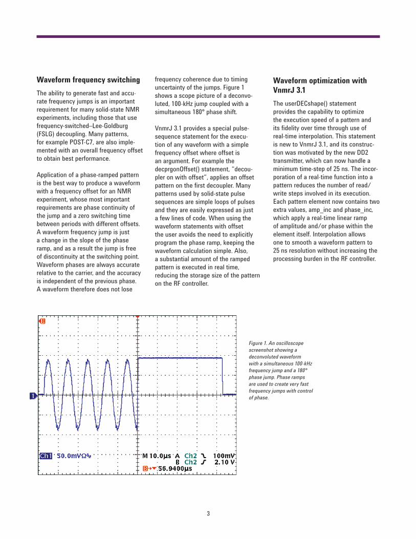
frequency coherence due to timing uncertainty of the jumps. Figure 1 shows a scope picture of a deconvo-luted, 100-kHz jump coupled with a simultaneous 180° phase shift.
VnmrJ 3.1 provides a special pulse-sequence statement for the execu-tion of any waveform with a simple frequency offset where offset is an argument. For example the decprgonOffset() statement, “decou-pler on with offset”, applies an offset pattern on the first decoupler. Many patterns used by solid-state pulse sequences are simple loops of pulses and they are easily expressed as just a few lines of code. When using the waveform statements with offset the user avoids the need to explicitly program the phase ramp, keeping the waveform calculation simple. Also, a substantial amount of the ramped pattern is executed in real time, reducing the storage size of the pattern on the RF controller.
Waveform frequency switchingThe ability to generate fast and accu-rate frequency jumps is an important requirement for many solid-state NMR experiments, including those that use frequency-switched–Lee-Goldburg (FSLG) decoupling. Many patterns, for example POST-C7, are also imple-mented with an overall frequency offset to obtain best performance.
Application of a phase-ramped pattern is the best way to produce a waveform with a frequency offset for an NMR experiment, whose most important requirements are phase continuity of the jump and a zero switching time between periods with different offsets. A waveform frequency jump is just a change in the slope of the phase ramp, and as a result the jump is free of discontinuity at the switching point. Waveform phases are always accurate relative to the carrier, and the accuracy is independent of the previous phase. A waveform therefore does not lose
Figure 1. An oscilloscope screenshot showing a deconvoluted waveform with a simultaneous 100-kHz frequency jump and a 180° phase jump. Phase ramps are used to create very fast frequency jumps with control of phase.
4
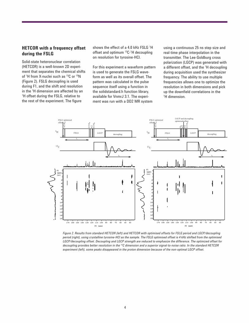
HETCOR with a frequency offset during the FSLGSolid-state heteronuclear correlation (HETCOR) is a well-known 2D experi-ment that separates the chemical shifts of 1H from X-nuclei such as 13C or 15N (Figure 2). FSLG decoupling is used during F1, and the shift and resolution in the 1H dimension are affected by an 1H offset during the FSLG, relative to the rest of the experiment. The figure
Figure 2. Results from standard HETCOR (left) and HETCOR with optimised offsets for FSLG period and LGCP/decoupling period (right), using crystalline tyrosine-HCl as the sample. The FSLG optimised offset is 4 kHz shifted from the optimised LGCP/decoupling offset. Decoupling and LGCP strength are reduced to emphasize the difference. The optimized offset for decoupling provides better resolution in the 13C dimension and a superior signal-to-noise ratio. In the standard HETCOR experiment (left), some peaks disappeared in the proton dimension because of the non-optimal LGCP offset.
shows the effect of a 4.0 kHz FSLG 1H offset and optimum 13C-1H decoupling on resolution for tyrosine-HCl.
For this experiment a waveform pattern is used to generate the FSLG wave-form as well as its overall offset. The pattern was calculated in the pulse sequence itself using a function in the solidstandard.h function library, available for VnmrJ 3.1. The experi-ment was run with a DD2 MR system
using a continuous 25 ns step size and real-time phase interpolation in the transmitter. The Lee-Goldburg cross polarization (LGCP) was generated with a different offset, and the 1H decoupling during acquisition used the synthesizer frequency. The ability to use multiple frequencies allows one to optimize the resolution in both dimensions and pick up the downfield correlations in the 1H dimension.
5
Waveforms for homonuclear decoupling during acquisitionWindowed homonuclear decoupling (classically known as CRAMPS, combined rotation and multiple-pulse spectroscopy) is a well-known method to obtain 1D 1H spectra. In recent years the traditional looped pulse sequences such as BR24 have been replaced with more complex sequences such as wFSLG (windowed FSLG), and a related sequence known as DUMBO. These modern sequences are best run as waveforms. Performance enhance-ments from interpolation using DD2 and some changes in VnmrJ 3.1 make that possible.
t1
tzf
t290°
1H POST-C7 XmX-eDUMBO
XmX-eDUMBO1
XmX-eDUMBO1
XmX-eDUMBO1POST-C7
acq
acq
acq
210-1-2
a.
b.
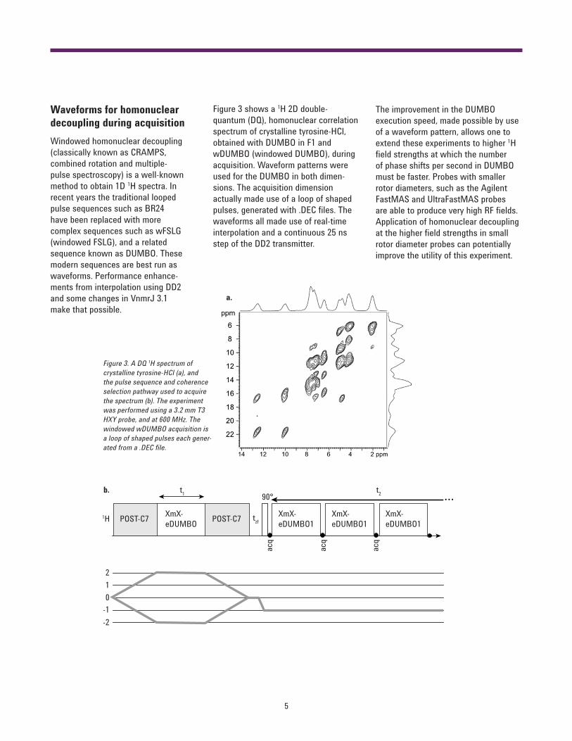
Figure 3. A DQ 1H spectrum of crystalline tyrosine-HCl (a), and the pulse sequence and coherence selection pathway used to acquire the spectrum (b). The experiment was performed using a 3.2 mm T3 HXY probe, and at 600 MHz. The windowed wDUMBO acquisition is a loop of shaped pulses each gener-ated from a .DEC file.
Figure 3 shows a 1H 2D double-quantum (DQ), homonuclear correlation spectrum of crystalline tyrosine-HCl, obtained with DUMBO in F1 and wDUMBO (windowed DUMBO), during acquisition. Waveform patterns were used for the DUMBO in both dimen-sions. The acquisition dimension actually made use of a loop of shaped pulses, generated with .DEC files. The waveforms all made use of real-time interpolation and a continuous 25 ns step of the DD2 transmitter.
The improvement in the DUMBO execution speed, made possible by use of a waveform pattern, allows one to extend these experiments to higher 1H field strengths at which the number of phase shifts per second in DUMBO must be faster. Probes with smaller rotor diameters, such as the Agilent FastMAS and UltraFastMAS probes are able to produce very high RF fields. Application of homonuclear decoupling at the higher field strengths in small rotor diameter probes can potentially improve the utility of this experiment.
6
The new DD2 digital phase shifterThe DD2 transmitter uses a new digital phase shifter to replace the quadrature-hybrid phase shifting of VNMRS and previous MR systems. The new phase shifter retains the < 50 ns phase-shift time of the previous hardware, but it has higher resolution with 16-bit, ~0.0055° set-ability and improved accuracy.
An NMR test, a looped 8-pulse [XYYXXYYX-acq]n windowed multi-pulse sequence, HS90, is used at Agilent to evaluate phase-shifting of new MR systems. The frequency offset of the NMR signal is plotted versus a phase correction to the Y pulses. Figure 4a shows the accuracy of phases over a 42° range. Figure 4b shows a set of 1-bit changes to the phase setting over a 0.22o range of phases. The resulting plot is linear, showing uncertainty at only the 1-bit level. The 16-bit phase shifts are indeed measurable by NMR. Figure 4c shows an electronic measurement that corroborates the NMR measurement. The HS90 pulse sequence for this test can be made available to users.
The desire for the finest transmitter phase resolution comes from the need for the many waveform patterns that use phases other than 90°. For example, the best known sequence of this type, POST-C7, makes use of (360.0°/7.0) phase shifts. Of course the quality of data from all these experiments is also due to other factors such as amplifiers and probes, which are outside the scope of this overview, but quality of the trans-mitter itself is of basic importance.
0
10
20
30
40
50
0 10 20 30 40 50
Mea
sure
d ph
ase
Set phase
2.19
2.24
2.29
2.34
2.39
2.44
2.19 2.24 2.29 2.34 2.39 2.44
Mea
sure
d ph
ase
Set phase
Figure 4. a) Phase measurements (0o-42o) obtained by NMR using the HS90 sequence and b) the same for 2.20o- 2.42o in ~0.0055o (1-bit) steps. c) An electronic measurement of phases for 0.0055o (1-bit) steps.
a.
b.
c.
7
AcknowledgmentsThe author wishes to thank Professor Arno Kentgens, Nijmegen University, whose group assisted in testing these new features and provided valuable suggestions.
ConclusionsThe waveform pattern is an important tool for the construction of NMR experi-ments with the DirectDrive MR systems from Agilent, including the most recent solid-state NMR methods. Use of wave-forms on Agilent DirectDrive systems maximizes hardware performance and flexibility for the designers of novel experiments. The new DirectDrive DD2 console also provides RF hardware and software improvements to improve both performance and flexibility for solid-state NMR experiments.
www.agilent.com
Product specifications and descriptions in this document are subject to change without notice.


![Encyclopedia of NMR - ABE-IPS · 2012-07-11 · Solid State NMR Studies of Biopolymers Anne E. McDermott, Tatyana Polenova The field of solid state NMR of biological samples [ssNMR]](https://static.documents.pub/doc/80x56/5f43f40d40e08d335c4d1e72/encyclopedia-of-nmr-abe-ips-2012-07-11-solid-state-nmr-studies-of-biopolymers.jpg)

