Direct Laser Fabrication of a Gas Turbine Engine Component - Microstructure and Properties - Part I Suman as', Timothy P. ~ u e s t i n ~ ~ , Gregory ~ a n ~ o ' , Lawrence E. Brownf, Joseph J. Beaman', David L. Bourelli, and Kathleen sargentB ?~aboratory for Freeform Fabrication University of Texas at Austin '~llison Engine Company, Inc. Indianapolis, Indiana $~ir Force Research Laboratory Wright Patterson AFB, Ohio Abstract This paper presents the development of a new technique for the production of abrasive turbine blade tips by direct laser processing. This superalloy cermet component is an integral part of the low pressure turbine sealing system in a demonstrator engine. Direct laser fabrication of this component fiom a bed a loose powder results in significant cost savings and improved performance over the currently employed production technique. The technology has been demonstrated by fabricating a prototype lot of 100 blade tips, which will be subjected to an engine test. This is the first instance of a direct fabrication method applied to the production of functional engine hardware. This research was funded by the United States Air Force contract F33615-94- C-2424 titled "Affordable Turbine Blade Tips". SUMMARY This program has contributed significantly towards meeting the Advanced Technology affordability goals for turbine engine acquisition. These goals require engines to be developed and maintained at a reduced cost. To meet some of these cost reduction goals, advanced manufacturing methods such as solid eeeform fabrication (SFF) must be applied. Although only one small turbine engine component is being discussed here, SFF in general has great potential for impacting cost reduction goals. The work performed is developmental, whch means fewer parts are produced regardless of the component. Since SFF costs are nearly independent of the number of ~arts', it will allow components to be fabricated at reduced cost. Since SFF has the potential to significantly reduce time from design conception to fabrication, it will also allow more design iterations to take place. The use of SFF to directly produce fbnctional components eliminates the costs and time associated with raw material acquisition, conversion and manufacture. The final goal of developing such a process would be to have the ability to control the microstructure with respect to precipitate size, density, porosity size and distribution, grain size, crystallographc texture and solidification modes. Such process control would allow production of components tailored with functionally graded microstructures to enhance properties and performance in specific regions of
Transcript
Direct Laser Fabrication of a Gas Turbine Engine Component - Microstructure and Properties - Part I
Suman as', Timothy P. ~ u e s t i n ~ ~ , Gregory ~ a n ~ o ' , Lawrence E. Brownf, Joseph J. Beaman', David L. Bourelli, and Kathleen sargentB
?~aboratory for Freeform Fabrication University of Texas at Austin
'~llison Engine Company, Inc. Indianapolis, Indiana
$ ~ i r Force Research Laboratory Wright Patterson AFB, Ohio
Abstract This paper presents the development of a new technique for the production of abrasive
turbine blade tips by direct laser processing. This superalloy cermet component is an integral part of the low pressure turbine sealing system in a demonstrator engine. Direct laser fabrication of this component fiom a bed a loose powder results in significant cost savings and improved performance over the currently employed production technique. The technology has been demonstrated by fabricating a prototype lot of 100 blade tips, which will be subjected to an engine test. This is the first instance of a direct fabrication method applied to the production of functional engine hardware. This research was funded by the United States Air Force contract F33615-94- C-2424 titled "Affordable Turbine Blade Tips".
SUMMARY
This program has contributed significantly towards meeting the Advanced Technology affordability goals for turbine engine acquisition. These goals require engines to be developed and maintained at a reduced cost. To meet some of these cost reduction goals, advanced manufacturing methods such as solid eeeform fabrication (SFF) must be applied. Although only one small turbine engine component is being discussed here, SFF in general has great potential for impacting cost reduction goals. The work performed is developmental, whch means fewer parts are produced regardless of the component. Since SFF costs are nearly independent of the number of ~a r t s ' , it will allow components to be fabricated at reduced cost. Since SFF has the potential to significantly reduce time from design conception to fabrication, it will also allow more design iterations to take place.
The use of SFF to directly produce fbnctional components eliminates the costs and time associated with raw material acquisition, conversion and manufacture. The final goal of developing such a process would be to have the ability to control the microstructure with respect to precipitate size, density, porosity size and distribution, grain size, crystallographc texture and solidification modes. Such process control would allow production of components tailored with functionally graded microstructures to enhance properties and performance in specific regions of
the component. This would represent the pinnacle of life and performance enhancement, and cost and schedule reduction.
SFF can also be applied to tooling production applications such as investment castings. Investment castings are used for complex geometries such as airfoils, where SFF can provide a means for prototyping tooling or patterns. These prototypes assist in production trials and iterations that are necessary to finalize geometry and processing2. Whether it is used for component or tooling manufacture, SFF is a critical area and a technology that is required to reduce the cost and lead time for producing turbine engine components.
INTRODUCTHON
Until recently, no work was reported on direct selective laser sintering (SLS) of high performance materials such as Nickel and Cobalt base superalloys, superalloy cermets9, Titanium base alloys3 and monolithic high temperature metals such as ~olybdenum~. These materials are used for high performance components that typically experience high operating temperatures, high stresses and severe oxidizing or corrosive environments. Direct SLS, with its ability to produce components in such materials is especially useful for functional prototype, low volume or "one of a kind" production runs. To manufacture a typical prototype lot of 100 superalloy cermet abrasive turbine blade tips, direct SLS was shown9 to achieve acceptable microstructure and properties with 80% cost savings over the traditional method. Automotive and aerospace industries face typical lead times of several weeks for functional, metallurgical quality prototypes. Direct SLS fabrication can lower cost and drastically reduce lead times by eliminating pre-
processing and post-processing steps, and by eliminating the need for specialized tooling.
Since its inception in the 1 930ts, the gas turbine engine has grown to be the workhorse power plant of modem aircraft. Advanced technology propulsion system are very important fi-om an overall system affordability viewpoint since higher engine performance can result in a smaller airfi-ame. SFF technologies are advanced manufacturing methods that can significantly impact cost reduction of engine components. SFF is striving towards decoupling cost from volume5 by making it possible to produce the first unit at a recurring cost equal to the hundredth unit6. To demonstrate SFF's cost-effectiveness, a superalloy cermet abrasive blade tip ( m T ) was chosen for direct fabrication technology development and demonstration.
. . . Gas turbine efficiency is highly dependent upon ing leakage of the gas away from
and around the working gas path. Therefore, clearance between rotating and static parts is critical. This clearance changes with component expansion and contraction due to the thermal cycling experienced in gas turbines. One of the primary methods developed to compensate for this expansion and contraction is an abradable seal This seal system works by a t tachg an ABT to the tips of the turbine blades. The stationary turbine shroud is coated with a abradable ceramic, which is abraded by the abrasive blade tip during engine operation to form a gas path seal around the rotating component. The abradable ceramic liner is relatively inexpensive and simple to manufacture. However, the abrasive cermet (0.9- 1.5 mm thickness) is difficult to manufacture on a production scale and contains expensive components. The cost of the raw
2
materials makes scrap highly undesirable. Due to the difficulties encountered9, a more reliable method for producing this material is desired. A direct SLS process for producing the cemet abrasive can provide a uniform, repeatable manufacturing process that would eliminate much of the manual labor, reduce scrap and make all unsintered surplus materials reusable.
OBJECTWES
Prior research9 in direct laser processing ABT cermet material had shown the capability of directly laser processing cermet material to obtain microstructure and properties that were consistent with production specifications. The ultimate goal of ongoing research was to complete technology development and demonstration of a direct laser manufacturing process capable of repeatably producing the ABT component to dimensional specifications, with microstructure and properties equivalent or superior to current production material. A prototype lot of 100 turbine blade tips would be manufactured to demonstrate the developed process and the associated efficiency.
During process development, the objectives were fourfold. The first objective was to investigate and establish a variety of material composition variants and processing conditions, and their effects on solidification microstructure, and mechanical properties. The second objective pertained to identification and specification of optimal processing windows for manufacturing the ABT component in a single pass laser scan. Under this objective, the optimal processing conditions would result in filly dense, fully melted and rapidly resolidified material free of solidification defects such as hot tearing, pinholing, entrapped porosity, grit floating or segregation. A third objective was to demonstrate reusability of unprocessed material. Atta* ' this objective would direcly impact cost effectiveness of the laser based manufacturing proce
ing scrap of expensive material constituents. The fourth and final objective was to prove consistency and repeatability of the laser process by producing a large number of ABT components in several experimental runs under identical processing conditions.
MATERULS AND METHODS
Cermet Specifications
The cermet in production is vacuum sintered using a Silicon and Boron containing Cobalt based braze alloy (Amdry 788) and subsequently bonded to the blade using a similar braze.
tion of the low melting point braze constituent could extend oxidation life and possibly allow higher operating temperatures. Higher operating temperatures could be achieved by replacing the braze used for bonding the ABT to the blade by a higher temperature diffusion braze. Currently, interactions between the component braze and the bonding braze prevent the use of a diffusion braze alloy. The goal of developing a brazeless cermet composition for direct laser processing was achieved during previous work9. This cermet is composed of Mar-M-247 nickel superalloy matrix (Table I), GE Borazon 510 (titanium coated cubic boron nitride) and Alundum 90 (titanium coated alumina). The thickness and chemical quality of the titanium coating on the abrasive grit is critical. Poor chemical quality of the coating causes contamination of the molten matrix alloy either through dissolution alone or in combination with spallation. A
titanium coating of non-uniform or insufficient thickness results in poor metallurgical bonding with the nickel matrix, and grit floating out of the melt due to large density and surface energy diRerences.
To meet homo geneity requirements, the sint er ed material must exInibit no discrete layering or agglomeration of abrasive particles which would result in grit pullout and associated decrease in seal efficiency. Porosity requirements allow for no more than 20% linear porosity as determined from a metallographic montage using a line intercept method. If the material meets these specifications, coupons are removed and brazed into the gauge section of a CMSX-4 single crystal test bar conforming to ASTM-E 139 and subjected to an application specific stress-rupture test.
Table 1. Nominal composition of matrix material used in the cermet.
Process Apparatus and Methods
A laser processing machine dedicated to the production of ABTs was designed jointly by the University of Texas and Allison Engine Company. The principle of operation of this machine is similar to a generic SLS machine. However, it has a few distinguishing features. Since one objective of ABT process development was to produce the full thickness (0.9-1.5 m) in a single laser pass, this machine does not provide multiple layer powder delivery. This machine is equipped with a 250 Watt CW Nd:YAG laser, high temperature powder heating capability and controlled atmosphere. Metal powders can be heated up to 1000°C in this workstation. This workstation has the capability of maintaining high vacuum (< 10'~ Torr) as well as high purity atmospheres of select gases. Custom software for CAD geometry processing was used to convert the electronic drawing of the demonstration ABT component into the desired laser scanning sequence. The machine control software allows the user to control and set processing parameters including preheat temperature cycle and setpoint, laser power, scan speed and scan spacing.
Material preparation for the direct SLS method consists of combining by weight 73% superalloy, 18% Ti coated alumina, and 9 % CBN. This mixture is blended for 4-6 hours prior to loading in the SLS chamber. The blended mixture is poured into a 4" diameter, 0.060-0.100" deep processing dish and leveled to produce a uniform thickness powder layer. The powder mixture was then baked out under high vacuum (< 5 xloW5 Torr) and with 25" C to 875" C temperature ramp over 30 minutes prior to SLS processing.
Direct SLS involves directly melting and consolidating selected regions of a powder bed to form a desired shape having full density. This method of fabrication involves melting the component matrix and obtaining the appropriate amount of flow f?om the molten material. The appropriate amount of flow is critical. It can be described as the produces a highly dense part maintaining dimensional tolerances an s other defects such as hot tearing, pitting, plnholing and solidification cracking. A number of experiments were
conducted to evaluate the influence of the most important SLS process parameters on the solidification behavior of this material composition. These parameters are atmosphere, preheat temperature, scanning sequence and energy density. The appropriate amount of flow is controlled by several factors such as atmosphere, degree of preheat and three characteristic variables affecting laser energy density: laser power, scan spacing and scan speed.
Rectangular coupons 1" long X 0.5" wide were produced by raster scanning across the width. These samples were used for process parameter development and mechanical testing. Tip shape processing was done by two alternate methods. The first method involved raster scanning the shape of a tip on a powder bed container. The second method was to laser process a rail shaped tip out of powder contained in a mold. The mold material directly affects the thermal profile generated and thus can be used in conjunction with preheat and laser scanning preheat to assist in control of the solidification microstructure of the component. The physical properties of the powder container influence the microstructure of the part dramatically. A ceramic powder container insulates the bottom surface of the powder bed and sets up a fairly unifonn thermal gradient which results in partial directional solidification or epitaxial growth. A more conductive powder, e.g. a steel or superalloy container can produce a very fine dendrite spacing in the solidification microstructure,
The laser scanning sequence significantly affects the thermal profile of the part during processing, therefore it will have a significant affect on tendency of the material to tear, crack and separate. The scanning sequence incorporated on actual parts will be dependent upon part geometry and modified in an attempt to provide a uniform thermal profile. This experiment involved only two variables on rectangular coupons, rastering the beam on continuously back and forth, and intermittently shutting the laser off and only rastering left to right. Scanning sequence can dramatically affect local solidification t b e , which affects dendrite spacing or solidification mode.
Traditional metallurgy practices dictate that the superalloy cermet material requires processing in a high vacuum atmosphere. However, a quick evaluation of the affects of different atmospheres was performed to document the degree of degradation. This consisted of perforrning trials in different types of atmospheres that included rough vacuum (of order 30mTorr), rough vacuum purged with argon, high vacuum (< 5 ~ 1 0 - ~ Torr) and high vacuum followed by argon-2% hydrogen backfill.
Experiments were conducted to determine the affects of preheating the powder bed in the range of 3 50°C to 1000°C vs. no preheat. The experimental results provided two fmdings. First, preheat was beneficial in that it hastened outgassing of the powder. Second, if a well outgassed powder was placed in the powder bed, the preheat improved the surface characteristics, wetting and flow, and minimized hot tearing or cracking. In general the components manufactured were more consistent in surface texture quality if a preheat is applied. Preheat could also be used to manipulate the thermal gradient during solidification which affects dendrite spacing and the mode of solidification.
rmw645-staff
Stamp
rmw645-staff
Stamp
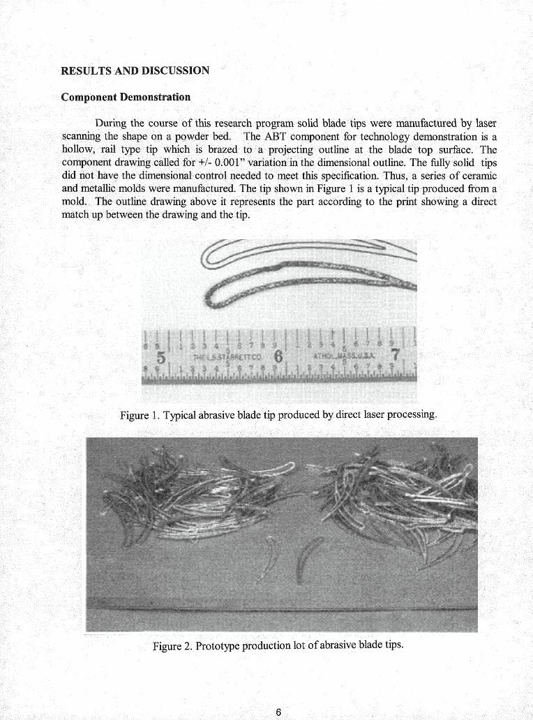
The life of the ceramic mold was not as long as desired, therefore a metallic mold was used to produce the components. A partial production lot of ABTs produced via this method is shown in Figure 2. The production yield was excellent, in excess of 95%. The mold was 0.090" deep and yielded parts that were in the 0.077 to 0.084" thck range. Subsequently, one surface was ground flat for bonding. The tips attained a final thickness in the 0.073 to 0.077" range.
Process Parameters for Production.
Precipitate strengthened nickel base superalloys are considered difficult to weld or work with in the molten state due to their tendency to strain age crack10911. Therefore, SLS processing parameters should be aimed at atta the most uniform thermal profile possible during processing to e the tendency for hot tearing and solidification cracking due to residual stresses and stresses resulting from aging during processing. This implies that a very fine scan spacing with a high scan speed should be incorporated. These two parameters also affect the surface roughness of the sintered coupon. A fine scan spacing will provide a relatively uniform smooth surface. Scan speed effects on surface roughness are dependent upon the overall energy density and the associated residence time in the molten region. For a given material a high scan speed with a high energy density which would produce extensive superheat or a long molten residence time will produce a poor surface finish. The same scan speed with a lower energy density and thus a lower degree of superheat will produce a better surface finish. In general excessive superheat will allow growth of morphological instabilities in solidification fiont s that produce non-uniform surface finish. Controlled heating, superheat, and cooling rate wdl produce a uniform solidification fiont thus producing a uniform surface appearance and microstructure. In general a fine scan spacing was chosen with the power and scan speed being variables used to deliver different energy densities. The goal was to produce a short molten residence time with full through thickness melting.
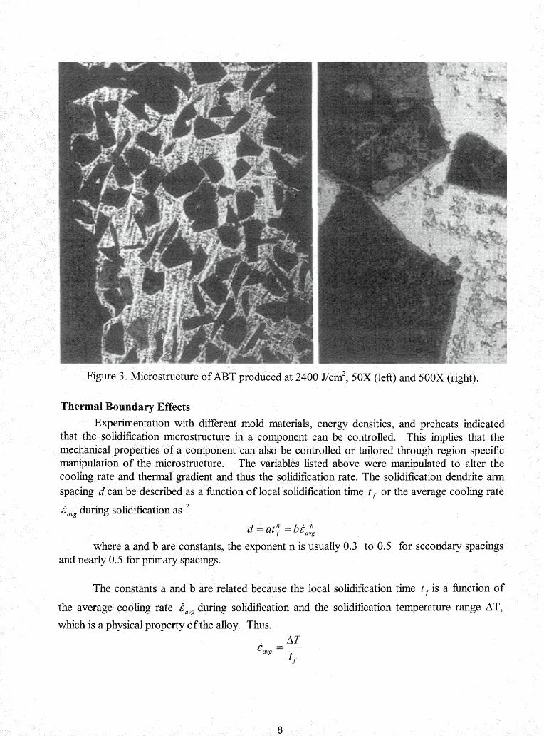
Prior process developmentg resulted in manufacture of test coupons (1 inch long, 0.5 inches wide and 0.060 inches thick) with acceptable microstructures for mechanical property characterization. The energy density used for producing these specimens was 3202 Jlcm2. In order to develop acceptable processing parameters for the ABT geometry, a number of experiments were conducted investigating a wide array of energy densities. These tests proved that the ABT component having acceptable microstructure and surface finish could be produced in the 2400 ~ l c r n ~ to 3878 ~ l c m ~ range. The microstructure produced at 2400 J/cm2 is shown in Figure 3.
Figure 3. Microstructure of ABT produced at 2400 ~ / c m ~ , 50X (left) and 500X (right).
Thermal Boundary Effects Experimentation with different mold materials, energy densities, and preheats indicated
that the solidification microstructure in a component can be controlled. This implies that the mechanical properties of a component can also be controlled or tailored through region specific manipulation of the microstructure. The variables listed above were manipulated to alter the cooling rate and thermal gradient and thus the solidification rate. The solidification dendrite arm spacing d can be described as a function of local solidification time t f or the average cooling rate
6,, during solidification as1
d = at.; = bk-" avg
where a and b are constants, the exponent n is usually 0.3 to 0.5 for secondary spacings and nearly 0.5 for primary spacings.
The constants a and b are related because the local solidification time t f is a function of
the average cooling rate i,, during solidification and the solidification temperature range AT,
which is a physical property of the alloy. Thus,
rmw645-staff
Stamp
The average cooling rate in turn is the product of the temperature gradient at the solid- liquid interface G and the velocity of the solidification front R. Thus,
It is evident that the temperature gradient and the solidification rate are easily manipulated through preheat, laser power density, scan speed, scan spacing and thermal boundary conditions at the mold-melt interface. Therefore the dendrite spacing as well as the solidification mode can be controlled through control of these parameters. For example, it has been shown9 that the solidification microstructure of SLS processed MAR-M-247 superalloy is a fbnction of laser energy density and thermal boundary conditions, ranging from fine-grain equiaxed to dendritic and directionally solidified. Mechanical properties such as fatigue can be improved through dendrite arrn spacing refinement.
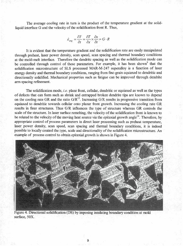
The solidification mode, i.e. plane front, cellular, dendritic or equiaxed as well as the types of defects that can form such as shrink and entrapped broken dendrite tips are known to depend on the cooling rate GR and the ratio G/R'~. Increasing GIR results in progressive transition from equiaxed to dendritic towards cellular onto planar front growth. Increasing the cooling rate GR results in finer structures. Thus GIR influences the type of structure whereas GR controls the scale of the structure. In laser surface remelting, the velocity of the solidification front is known to be related to the velocity of the moving heat source via the epitaxial growth angle"! Therefore, by appropriate control of process parameters in direct laser processing such as preheat temperature, laser power density, scan speed, scan spacing and thermal boundary conditions, it is indeed possible to locally control the type, scale and directionality of the solidification microstructure. An example of process control to obtain epitaxial growth is shown in Figure 4.
rmw645-staff
Stamp
Direct Laser Fabrication of a Gas Turbine Engine Component - Microstructure and Properties - Part II
Processing Atmosphere
Both rough vacuum and the purged argon contained sufficient oxygen to oxidize the molten alloy thus causing balling, separation, and tearing due to surface tension effects. The high vacuum atmosphere resulted in relatively uniform surface features, no cracking, tearing or separation when experimentation was conducted within an acceptable window of parameters. Volatilization of low vaporization temperature elements may be a concern depending upon preheat temperature and alloy composition. Volatilization can lead to problem with alloy depletion and or laser energy inconsistencies over long periods of time.
Reactive metal coating thickness and quality
Two vendors were evaluated for depositing the reactive metal coating on the abrasive ceramic grit. Significant differences were noted in how the product perfomed when subjected to the SLS process. In some instances the SLS preform would simply disintegrate while in other instances the preform was not sufficiently strong to withstand surface grinding. Internal contamination of the superalloy matrix was noted on the microstmcture of these specimens. In other cases the components perfomed flawlessly in all aspects. An analysis of the coating deposited on the abrasive grits explained the differences.
Coated grit from two vendors were metallographically analyzed for coating thickness and uniformity. The photomicrographs shown in Figure 5 illustrate the difference in coating thickness and uniformity. The titanium coating thickness on Brand B is greater and much more uniform than of Brand A. Consequently, the Brand B material always performed better. However it was also noted that when the Brand A coating thickness was increased, the performance of Brand A still did not compare to that of Brand B. It was also noted that when only the Borazon 510 CBN (titanium coated cubic boron nitride) was used in the powder mixture the results were excellent. Therefore, chemical analysis of the Ti coating on both Brand A and Brand B titanium coated alumina as well as the Borazon 5 10 CBN was performed. The contaminants C, 0, and N were of interest. Signifcant levels of these contaminants could dramatically diminish the performance of the Ti coating and consequently the overall integrity of the laser processed cermet.
Two types of analyses were conducted in order to detemrine the contaminant content in the Ti coating. Auger analysis with intermittent ion milling from the surface of the particle provided data at different depths of the coatings. The data fiom this analysis is shown in Table 2 and Figure 5, Figure 6 and Figure 7. The tabular data at different depths indicates that the surface layers of all coatings analyzed were severely contaminated. A signifcant drop in co level was noted at 1000 A on all coatings, however the levels were still extremely high. A a large drop to relatively pure material was noted on the CBN coating while both the Brand A and Brand B dropped to near similar levels with Brand A having the highest overall cont level. At 5000 A only the CBN still possessed coating. The CBN's titanium coating at 5000 A was relatively pure. The data from the Auger Analysis indicated that the overall thickness and uniformity as well as purity at depths of approximately 1000 A is of high importance in
e. Auger analysis could not discern nitrogen fiom titanium because of peak overlap. roprobe analysis was conducted on cross-sectioned samples.
Atodc % Concentrations
CE3N
Brand B - 5.2 wt %
Brand A - 5.2 wt %
Brand A - 2.4 wt. %
# - Surface was charging too much to obtain data. This indicates that there was no free titanium or carbon * - Lack of data indicates that base particle had been exposed by ion milling. Note: Nitrogen cannot be discerned because nitrogen peak overlaps with titanium peak.
Table 2. Auger chemical analysis of titanium coating.
rmw645-staff
Stamp
Titanium Content vs Coating Depth
100.0
80 .0 - -- - - - -.
s = CBN
8 ,OeO
I I -4- rand B - 5.2 wt.
0 40.0 2 1 %
20.0 rand^ - 5.2 wt%
0.0 i-BrandA-2.4wt j % 0 2000 4000 6000 I - -_
Depth in Angstroms 1 Figure 6. Titanium coating purity vs. coating depth.
- -- -- -. - - - - --
Oxygen Content vs Coating Depth I I
i
-€I-- Brand B -
+Brand A -
I 0 low 2000 3m0 40W 5000 M)W
Depth in Angstroms
Figure 7. Oxygen content vs. titanium coating depth.
Carbon Content vs Coating Depth
Figure 8 Carbon content vs. titanium coating depth.
The results of rnicrobrobe analysis are shown in Table 3. The microprobe analysis also suggested that the CBN had the purest titanium coating. Brand A coating did have a much higher nitrogen content than Brand B with the overall contaminant content being similar. When a composite contaminant level is calculated for each of the abrasive grits using the C and 0 Auger data at 1000 Angstrom and the N levels from the microprobe analysis, a clearer picture of the performance is evident. The CBN composite contaminant content is approximately 28 atomic %, The Brand B Ti coated alumina is approximately 42%, While that of Brand A is approximately 63%. The chemical analysis data indicates that there is a significant difference in the coating purity of the three different grits. The results of the SLS trials combined with the chemical and metallurgical analysis indicated that the coating's uniformity and overall chemical purity are all equally important. The coating thickness is also important. However, the presence of significant residual coating on SLS processed specimens such as that shown earlier in Figure 3 indicate that the coating's thickness is not as important as uniformity or chemical purity.
Microprobe Data for Cross - Sectioned Grit Samples
Table 3. Microprobe data for cross-sectioned grit samples.
Effect of Dopants
Due to some of the processing difficulties encountered because of the coating uniformity and purity, an experiment involving doping was performed. Doping consists of adding a material to the cermet mixture that would assist in scrubbing and breaking down the highly contaminated surface of the Ti coating on the grit particle and also assist in cleaning the remainder of the melt. Scmbbhg of the Ti coating is necessary in order to clean the refractory type surface and activate the more pure underlying Ti in order to improve the wetting and bonding with the superalloy matrix. Different methods were evaluated for adding various levels of free Ti to the melt. Other elements that have been evaluated as dopants are F and Y. Both methods yielded promising results. In addition to Ti doping, multiple coatings were also evaluated. The coating in this case
Stress-rupture and rub-testing of SLS processed ABT cermet material have been reported The stress rupture samples were divided into two distinct groups: ABT specimens
with uniform surface appearance and ABT specimens with some "acceptable" levels of pitting and
rmw645-staff
Stamp
porosity. The surface condition did not produce any difference in stress mpture properties. An additional variable involved el ating the 2 1 50°F/32 hour standard diffusion cycle from some of the specimens. ion of the braze diffusion heat treat cycle significantly improves the properties of th -4 base material. The stress-rupture data in Larson Miller form is shown in Figure 10. The testing was conducted in the temperature range of 1900°F to 2200°F with some of the samples tested in excess of 500 hrs. The samples brazed without the diasion heat treat cycle exhibited slightly reduced life. All samples failed in the braze joint and did not traverse the SLS material. This indicates that the plot of Figure 1 0 is actually a representation of the braze bond strength. Standard production material exhibits failur traverse through the center of the cemet because of the braze component in the standard e. Therefore thjis difference h failure mode indicates an improvement in temperature capability of the laser processed cemet. These results imply that the brazeless material composition processed by direct SLS is superior to the standard cemet.
brson Miller Parameter - P 0.00l * {T +460)*(log(t)+20))
Figure 10. Stress-Rupture of CMSX-4 bar with ABT brazed in-gage.
The primary goal of future work is to develop a laser process for direct tipping. Direct tipping is perfo SLS on top of the turbine blade and actually bonding the cemet layer to the blade at the same time that melting and densification is occuning. A laser based process that fabricates abrasive tips directly onto turbine blades will yield three important benefits. The first and most important potential benefit is that the base material of the blade will have substantially better mechanical properties since it will not be exposed to either the braze or diffusion thermal cycles. Both the braze and diffusion cycles involve high temperatures and long times which degrade the microstructure and mechanical properties of the base material.
cycles will allow higher design mechanical properties temperatures, potentially resulting in designs that improve eficienc y. Second, the need for
tooling and the intensive labor associated with preparing and brazing tips to blades will be eliminated. Thrd, mechanical properties of the tip-blade bond interface will be improved as a result of epitaxial solidification of the tip material off the blade base material.
Additional goals of the fiture include incorporating process understanding and control such that region specific or tailored microstmctures can be produced. This ability could significantly improve the performance of a given region or component overall thus increasing expected life. Such achievements may also allow the repair of single crystal turbine hardware to original conditions or the production of super plastically formable components of a given alloy which were not available previously. The total control over processing environment should favor technological breakthroughs in the manufacture of net shape components in extremely difficult to process high performance materials such as refractories, in-situ composites, and intermetallics.
CONCLUSIONS
A successfil direct SLS process was developed and approximately 100 tips produced. The process developed achieved all of the objectives and goals originally set forth. The goals are listed below .
1. Raw material input is proportional to quantity of tips needed.
2. Fall off materials are reusable.
3. Majority of processing steps of standard production process eliminated.
4. Process produces the hlly dense component in a single pass by achieving hll through thickness melting.
5. Mechanical properties were improved by eliminating the cobalt braze material from the cermet composition .
6. Elimination of Processing steps, scrap, fall off, and input stock required produced cost savings in excess of that originally calculated.
7. Microstructure, properties and performance are superior to that of the standard production material.
In addition to achieving all of the original program goals and outlining parametric windows, important information was noted concerning the effects of preheat temperature, processing atmosphere, thermal boundary effects, energy density, dopants, and reactive metal coating quality on ceramic grit in cermets. Some of these effects are summarized as follows.
Preheating the powder bed has been shown to be beneficial by outgassing the powder thus preventing firther contamination during processing. Preheat was also noted to improve the uniformity of flow and solidification of the molten material, thus enhancing the surface finish
uniformity of the final component. It is also known that preheat to appropriate temperatures also reduces hot tearing, hot cracking, and balling of the molten material.
Energy density and the associated parameters of laser power, scan spacing, and scan speed were crucial in minimizing hot tearing, balling and cracking. Without the proper selection of energy density parameters significant porosity, incomplete through thickness melting, and very poor surface fimsh may result.
The SLS apparatus developed during this program allows total process control. The extent of process control capability allows the manipulation of thermal boundary effects and solidification rates. This in turn may be used in the future to tailor region specific microstructures. Experiments conducted during this program illustrate that it is possible to dramatically
manipulate the microstructure of the material.
The experimentation with different types of abrasive grit, Ti coatings and contaminant analysis revealed the importance of uniformity and purity of the reactive metal coating in the processability, performance and properties of cermets produced by direct SLS. High quality coatings can result in the difference between failure and success.
Dopants were evaluated in an attempt to overcome the detrimental affects of the poor quality reactive metal coatings. The usefulness of dopants to improve melt cleanliness and activate the reactive metal coating on the abrasive grit to enhance bonding was demonstrated. However, caution should be exercised with dopants due to secondary affects resulting from alloy chemistry modification. The coated grits used for production were of sufficient quality that a dopant was not necessary to provide a robust production process. However, dopants may be very beneficial if one were to produce a very large part or multiple layer part.
ACKNOWLEDGEMENTS
Partial funding for this work was provided by the United States Air Force, Contract No. F336 15-94-C-2424. The remainder of resources were provided by Allison Engine Company and the University of Texas at Austin.
1 Marcus, H.L and D. L. Bourell, Solid Freeform Fabrication Finds New Applications, Advanced Materials & Processes, Volume 144, No.3, September 1993.
' Proceedings of a Technical Interchange Meeting on "Metals/Processing for Engine Aaordability", 9-10 April 1996, Williamsburg, VA.
Das, S. et al., Processing of Titanium Net Shapes by SLSIHIP, 1998 Solid Freeform Fabrication Symposium Proceedings.
4 Das, S. et al., Selective Laser Sintering of High Temperature High Perfomance Materials, 1996 Solid Freeform Fabrication Symposium Proceedings.
proceeding^ of the First Air Force, Wright Laboratory S&T Affordability Exit Criteria Workshop.
Dk, D.M. and Riddell, F.R., Projecting Cost-Performance Trade-offsfor Militaly Vehicles, Attachment to Anita Jones letter to JAST program office on IHPTET AFFORDABILTY, dated 3 1 August 1994, Aeronautics & Astronautics, September 1976.
Yeaple, F., Gas Turbine Rotor Grinds Own Tip Seals, Design News, 1-5-87, pp. 106-107.
* Helms, Harold E. et al., Ceramic Apglications in Turbine Engines, Noyes Publications, Park Ridge, New Jersey, 1986, pp. 13 1-137.
9 Fuesting, T. et al., Development of Direct SLS Processing for Production of Cermet Composite Turbine Sealing Components, 1996 Solid Freeform Fabrication Symposium Proceedings.
lo Welding Handbook - Materials and Applications Part 1, American Welding Institute, 550 N.W. Lejeune Road, Miami, FL.
11 Sims, Chester T., Norman S. Stoloff and William C. Hagel, eds., Superalloys 11 - High Temperature Materialsfor Aerospace and Industrial Power, Wiley-Interscience, 1987.
12 Flemings, M.C., Solidz~cation Processing, McGraw-Ha, 1974, pp. 148.
13 Breinan, E.M. and B. H. Kear, Rapid Solidification Laser Processing at High Power Density, in Laser Materials Processing, Vol. 3 of Materials Processing Theory and Practices, North-Holland, 1983, pp. 239-255.
l4 Carmpt, B., M. Rappaz and M. Z IV, TMS, 1988, p. 581.