Direct mapping of local director field of nematic liquid crystals at the nanoscale Yu Xia a , Francesca Serra a,b,c , Randall D. Kamien b , Kathleen J. Stebe c , and Shu Yang a,1 a Department of Materials Science and Engineering, University of Pennsylvania, Philadelphia, PA 19104; b Department of Physics and Astronomy, University of Pennsylvania, Philadelphia, PA 19104; and c Department of Chemical and Biomolecular Engineering, University of Pennsylvania, Philadelphia, PA 19104 Edited by David A. Weitz, Harvard University, Cambridge, MA, and approved November 9, 2015 (received for review July 7, 2015) Liquid crystals (LCs), owing to their anisotropy in molecular ordering, are of wide interest in both the display industry and soft matter as a route to more sophisticated optical objects, to direct phase separa- tion, and to facilitate colloidal assemblies. However, it remains challenging to directly probe the molecular-scale organization of nonglassy nematic LC molecules without altering the LC directors. We design and synthesize a new type of nematic liquid crystal mono- mer (LCM) system with strong dipole–dipole interactions, resulting in a stable nematic phase and strong homeotropic anchoring on silica surfaces. Upon photopolymerization, the director field can be faith- fully “locked,” allowing for direct visualization of the LC director field and defect structures by scanning electron microscopy (SEM) in real space with 100-nm resolution. Using this technique, we study the nematic textures in more complex LC/colloidal systems and calculate the extrapolation length of the LCM. nematic liquid crystal polymers | dipole–dipole interactions | topological defects | photo-cross-linking | nanoscale imaging U biquitous as they are, it sometimes escapes our attention that liquid crystals (LCs) are the original nanomaterial. The manipulation of these nanometer-size molecules into coherent, centimeter-scale structures is now routine. Although we have become adept at deducing textures indirectly through optical mi- croscopies (1–5), probing the molecular-scale organization requires either a glassy material or rapid cooling of samples, providing metastable states that can be directly visualized through scanning electron microscopy (SEM), transmission electron microscopy (TEM), and atomic force microscopy (AFM) (6–8). Although these techniques are effective to study a variety of more complex LC phases, including smectic LCs (6, 7, 9), cholesteric and blue phases (10), and biological LC polymers (11, 12), nonglassy, low molecular weight nematic LCs (NLCs) reorient during fast freez- ing. Polymer nematics can be quenched into metastable states but organization of static configurations through surface alignment is difficult. Flow alignment can be used but that often precludes complex, molecular scale patterning of the boundary conditions, essential for controlling and manipulating topological defects (13, 14). Although an undesired nuisance in NLC displays, topological defects mediate many of the rich interactions between colloids in NLCs (15). The defects, bearing quantized topological charge, resemble the defects in superconductors (16), soft ferromagnets (17), and even cosmic strings and monopoles (18). The fluidity of the phase and the weakly first-order nematic–isotropic phase transition allow for direct visualization of the creation/annihilation of defects via the Kibble–Zurek mechanism (19). Further, defects in a flat sheet of nematic gel or glass can be used to bend or twist local directors, inducing 3D shapes (20, 21). It is therefore critical to be able to characterize the defect structures at the nanoscale in a variety of settings. Here, we report the design and synthesis of a nematic liquid crystal monomer (LCM) system that has strong homeotropic anchoring on silica surfaces and does not reorient its director field during polymerization. Thus, the optical signatures remain unchanged in the liquid crystal polymers (LCPs), allowing for direct visualization of the defect structures by SEM in real space with 100-nm resolution. Using this technique, we study the nematic textures in more complex LC/colloidal systems and esti- mate the ratio between elastic and anchoring constants, i.e., the extrapolation length, of LCMs in the nematic phase. Results and Discussion Visualization of topological defects has been achieved by dis- persing polymer fibers in prealigned, low molecular weight NLC (22, 23). However, the polymer fibers, fabricated in situ via po- lymerization of LCMs, often phase separate from the nematic host; thus maintaining the LC director field in a nonglassy ne- matic host for direct visualization is thwarted. Moreover, the fibers themselves can perturb the nematic phase, inducing arti- facts and spurious defects. Of course, to visualize the native di- rector field responding to geometric surface cues we must use molecules that can be aligned reliably at interfaces of different topology, topography, and surface chemistry. Typically, the alignment of LCMs is controlled via mechanical rubbing of a polymer layer, use of a photo-alignment layer (21), mechanical stretching, or application of magnetic fields (24–28). However, these techniques are limited in their spatial resolution, especially in comparison with the highly refined ability to impart chemical anchoring on boundaries with complex topography and topology at the micro- and nanoscales, and also require high uniformity across the large sample areas. Although functional LCMs have been used for decades in conjunction with LCPs as actuators and sensors (24–29), it remains challenging to achieve faithful anchor- ing control at the level of the old stalwart, 4-cyano-4′-pentylbiphenyl (5CB). Meanwhile, slow relaxation of the bulk director field will lead to spurious defects in LCMs (or polydomain configurations) as shown in SI Appendix, Fig. S1 from widely used LCMs in the Significance It has been challenging to directly probe the molecular-scale organization of nonglassy nematic liquid crystal (LC) molecules without altering the LC directors. Here, we design and syn- thesize a new type of stable nematic liquid crystal monomer (LCM) system with strong dipole–dipole interactions. The new LCMs can achieve faithful anchoring and alignment control at various boundaries, analogous to that of small molecule LCs. Upon photo-cross-linking, the orientational order of mesogens is effectively and faithfully locked, allowing for direct visuali- zation of the LC director field and defect structures by scanning electron microscopy (SEM) with 100-nm resolution. Further, we use SEM imaging to calculate the extrapolation length of the LCM for planar and homeotropic anchoring. Author contributions: Y.X. and S.Y. designed research; F.S. helped with microscopy mea- surements; Y.X. performed research; Y.X., F.S., R.D.K., K.J.S., and S.Y. analyzed data; and Y.X., F.S., R.D.K., K.J.S., and S.Y. wrote the paper. The authors declare no conflict of interest. This article is a PNAS Direct Submission. 1 To whom correspondence should be addressed. Email: [email protected]. This article contains supporting information online at www.pnas.org/lookup/suppl/doi:10. 1073/pnas.1513348112/-/DCSupplemental. www.pnas.org/cgi/doi/10.1073/pnas.1513348112 PNAS | December 15, 2015 | vol. 112 | no. 50 | 15291–15296 APPLIED PHYSICAL SCIENCES
Transcript
Direct mapping of local director field of nematic liquidcrystals at the nanoscaleYu Xiaa, Francesca Serraa,b,c, Randall D. Kamienb, Kathleen J. Stebec, and Shu Yanga,1
aDepartment of Materials Science and Engineering, University of Pennsylvania, Philadelphia, PA 19104; bDepartment of Physics and Astronomy, Universityof Pennsylvania, Philadelphia, PA 19104; and cDepartment of Chemical and Biomolecular Engineering, University of Pennsylvania, Philadelphia, PA 19104
Edited by David A. Weitz, Harvard University, Cambridge, MA, and approved November 9, 2015 (received for review July 7, 2015)
Liquid crystals (LCs), owing to their anisotropy in molecular ordering,are of wide interest in both the display industry and soft matter as aroute to more sophisticated optical objects, to direct phase separa-tion, and to facilitate colloidal assemblies. However, it remainschallenging to directly probe the molecular-scale organization ofnonglassy nematic LC molecules without altering the LC directors.We design and synthesize a new type of nematic liquid crystal mono-mer (LCM) systemwith strong dipole–dipole interactions, resulting ina stable nematic phase and strong homeotropic anchoring on silicasurfaces. Upon photopolymerization, the director field can be faith-fully “locked,” allowing for direct visualization of the LC director fieldand defect structures by scanning electron microscopy (SEM) in realspace with 100-nm resolution. Using this technique, we study thenematic textures in more complex LC/colloidal systems and calculatethe extrapolation length of the LCM.
Ubiquitous as they are, it sometimes escapes our attentionthat liquid crystals (LCs) are the original nanomaterial. The
manipulation of these nanometer-size molecules into coherent,centimeter-scale structures is now routine. Although we havebecome adept at deducing textures indirectly through optical mi-croscopies (1–5), probing the molecular-scale organization requireseither a glassy material or rapid cooling of samples, providingmetastable states that can be directly visualized through scanningelectron microscopy (SEM), transmission electron microscopy(TEM), and atomic force microscopy (AFM) (6–8). Althoughthese techniques are effective to study a variety of more complexLC phases, including smectic LCs (6, 7, 9), cholesteric and bluephases (10), and biological LC polymers (11, 12), nonglassy, lowmolecular weight nematic LCs (NLCs) reorient during fast freez-ing. Polymer nematics can be quenched into metastable states butorganization of static configurations through surface alignment isdifficult. Flow alignment can be used but that often precludescomplex, molecular scale patterning of the boundary conditions,essential for controlling and manipulating topological defects (13,14). Although an undesired nuisance in NLC displays, topologicaldefects mediate many of the rich interactions between colloids inNLCs (15). The defects, bearing quantized topological charge,resemble the defects in superconductors (16), soft ferromagnets(17), and even cosmic strings and monopoles (18). The fluidity ofthe phase and the weakly first-order nematic–isotropic phasetransition allow for direct visualization of the creation/annihilationof defects via the Kibble–Zurek mechanism (19). Further, defectsin a flat sheet of nematic gel or glass can be used to bend or twistlocal directors, inducing 3D shapes (20, 21). It is therefore criticalto be able to characterize the defect structures at the nanoscale in avariety of settings. Here, we report the design and synthesis of anematic liquid crystal monomer (LCM) system that has stronghomeotropic anchoring on silica surfaces and does not reorient itsdirector field during polymerization. Thus, the optical signaturesremain unchanged in the liquid crystal polymers (LCPs), allowingfor direct visualization of the defect structures by SEM in realspace with 100-nm resolution. Using this technique, we study the
nematic textures in more complex LC/colloidal systems and esti-mate the ratio between elastic and anchoring constants, i.e., theextrapolation length, of LCMs in the nematic phase.
Results and DiscussionVisualization of topological defects has been achieved by dis-persing polymer fibers in prealigned, low molecular weight NLC(22, 23). However, the polymer fibers, fabricated in situ via po-lymerization of LCMs, often phase separate from the nematichost; thus maintaining the LC director field in a nonglassy ne-matic host for direct visualization is thwarted. Moreover, thefibers themselves can perturb the nematic phase, inducing arti-facts and spurious defects. Of course, to visualize the native di-rector field responding to geometric surface cues we must usemolecules that can be aligned reliably at interfaces of differenttopology, topography, and surface chemistry. Typically, thealignment of LCMs is controlled via mechanical rubbing of apolymer layer, use of a photo-alignment layer (21), mechanicalstretching, or application of magnetic fields (24–28). However,these techniques are limited in their spatial resolution, especiallyin comparison with the highly refined ability to impart chemicalanchoring on boundaries with complex topography and topologyat the micro- and nanoscales, and also require high uniformityacross the large sample areas. Although functional LCMs havebeen used for decades in conjunction with LCPs as actuators andsensors (24–29), it remains challenging to achieve faithful anchor-ing control at the level of the old stalwart, 4-cyano-4′-pentylbiphenyl(5CB). Meanwhile, slow relaxation of the bulk director field will leadto spurious defects in LCMs (or polydomain configurations) asshown in SI Appendix, Fig. S1 from widely used LCMs in the
Significance
It has been challenging to directly probe the molecular-scaleorganization of nonglassy nematic liquid crystal (LC) moleculeswithout altering the LC directors. Here, we design and syn-thesize a new type of stable nematic liquid crystal monomer(LCM) system with strong dipole–dipole interactions. The newLCMs can achieve faithful anchoring and alignment control atvarious boundaries, analogous to that of small molecule LCs.Upon photo-cross-linking, the orientational order of mesogensis effectively and faithfully locked, allowing for direct visuali-zation of the LC director field and defect structures by scanningelectron microscopy (SEM) with 100-nm resolution. Further, weuse SEM imaging to calculate the extrapolation length of theLCM for planar and homeotropic anchoring.
Author contributions: Y.X. and S.Y. designed research; F.S. helped with microscopy mea-surements; Y.X. performed research; Y.X., F.S., R.D.K., K.J.S., and S.Y. analyzed data; andY.X., F.S., R.D.K., K.J.S., and S.Y. wrote the paper.
The authors declare no conflict of interest.
This article is a PNAS Direct Submission.1To whom correspondence should be addressed. Email: [email protected].
This article contains supporting information online at www.pnas.org/lookup/suppl/doi:10.1073/pnas.1513348112/-/DCSupplemental.
literature; this inherent obstacle becomes increasingly obviousunder complex confinement.To address this, we specially designed and synthesized a series of
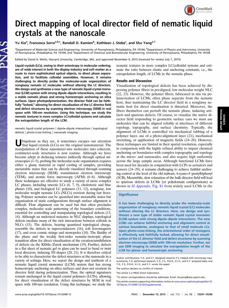
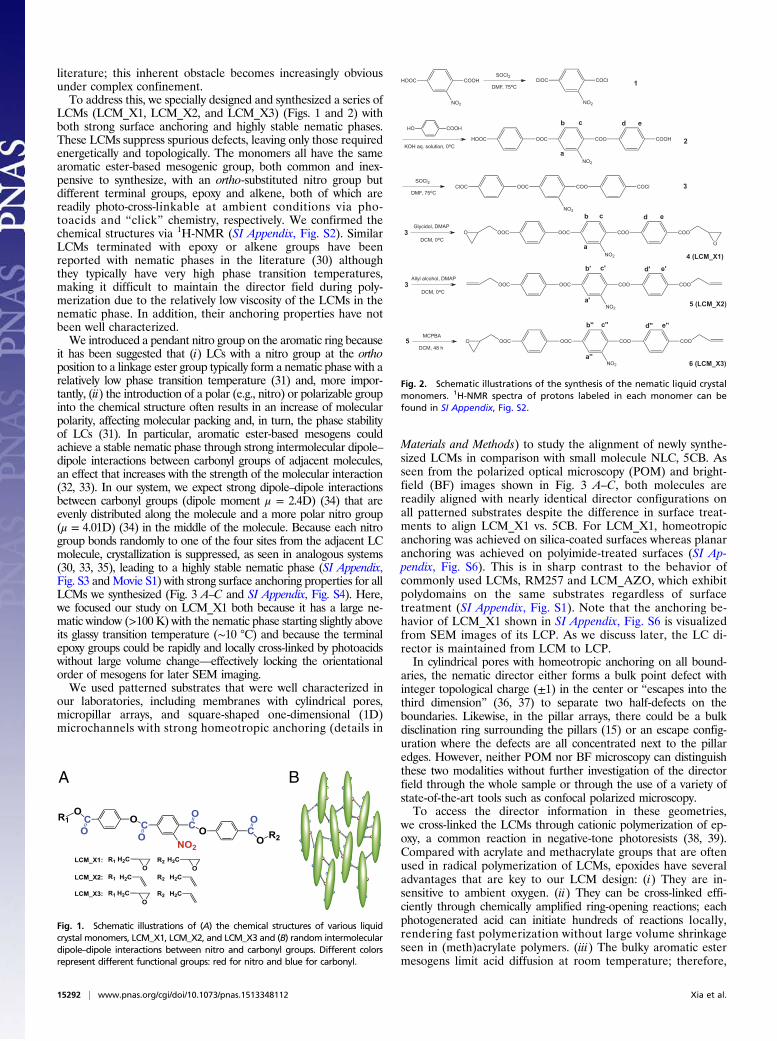
LCMs (LCM_X1, LCM_X2, and LCM_X3) (Figs. 1 and 2) withboth strong surface anchoring and highly stable nematic phases.These LCMs suppress spurious defects, leaving only those requiredenergetically and topologically. The monomers all have the samearomatic ester-based mesogenic group, both common and inex-pensive to synthesize, with an ortho-substituted nitro group butdifferent terminal groups, epoxy and alkene, both of which arereadily photo-cross-linkable at ambient conditions via pho-toacids and “click” chemistry, respectively. We confirmed thechemical structures via 1H-NMR (SI Appendix, Fig. S2). SimilarLCMs terminated with epoxy or alkene groups have beenreported with nematic phases in the literature (30) althoughthey typically have very high phase transition temperatures,making it difficult to maintain the director field during poly-merization due to the relatively low viscosity of the LCMs in thenematic phase. In addition, their anchoring properties have notbeen well characterized.We introduced a pendant nitro group on the aromatic ring because
it has been suggested that (i) LCs with a nitro group at the orthoposition to a linkage ester group typically form a nematic phase with arelatively low phase transition temperature (31) and, more impor-tantly, (ii) the introduction of a polar (e.g., nitro) or polarizable groupinto the chemical structure often results in an increase of molecularpolarity, affecting molecular packing and, in turn, the phase stabilityof LCs (31). In particular, aromatic ester-based mesogens couldachieve a stable nematic phase through strong intermolecular dipole–dipole interactions between carbonyl groups of adjacent molecules,an effect that increases with the strength of the molecular interaction(32, 33). In our system, we expect strong dipole–dipole interactionsbetween carbonyl groups (dipole moment μ = 2.4D) (34) that areevenly distributed along the molecule and a more polar nitro group(μ = 4.01D) (34) in the middle of the molecule. Because each nitrogroup bonds randomly to one of the four sites from the adjacent LCmolecule, crystallization is suppressed, as seen in analogous systems(30, 33, 35), leading to a highly stable nematic phase (SI Appendix,Fig. S3 andMovie S1) with strong surface anchoring properties for allLCMs we synthesized (Fig. 3 A–C and SI Appendix, Fig. S4). Here,we focused our study on LCM_X1 both because it has a large ne-matic window (>100 K) with the nematic phase starting slightly aboveits glassy transition temperature (∼10 °C) and because the terminalepoxy groups could be rapidly and locally cross-linked by photoacidswithout large volume change—effectively locking the orientationalorder of mesogens for later SEM imaging.We used patterned substrates that were well characterized in
our laboratories, including membranes with cylindrical pores,micropillar arrays, and square-shaped one-dimensional (1D)microchannels with strong homeotropic anchoring (details in
Materials and Methods) to study the alignment of newly synthe-sized LCMs in comparison with small molecule NLC, 5CB. Asseen from the polarized optical microscopy (POM) and bright-field (BF) images shown in Fig. 3 A–C, both molecules arereadily aligned with nearly identical director configurations onall patterned substrates despite the difference in surface treat-ments to align LCM_X1 vs. 5CB. For LCM_X1, homeotropicanchoring was achieved on silica-coated surfaces whereas planaranchoring was achieved on polyimide-treated surfaces (SI Ap-pendix, Fig. S6). This is in sharp contrast to the behavior ofcommonly used LCMs, RM257 and LCM_AZO, which exhibitpolydomains on the same substrates regardless of surfacetreatment (SI Appendix, Fig. S1). Note that the anchoring be-havior of LCM_X1 shown in SI Appendix, Fig. S6 is visualizedfrom SEM images of its LCP. As we discuss later, the LC di-rector is maintained from LCM to LCP.In cylindrical pores with homeotropic anchoring on all bound-
aries, the nematic director either forms a bulk point defect withinteger topological charge (±1) in the center or “escapes into thethird dimension” (36, 37) to separate two half-defects on theboundaries. Likewise, in the pillar arrays, there could be a bulkdisclination ring surrounding the pillars (15) or an escape config-uration where the defects are all concentrated next to the pillaredges. However, neither POM nor BF microscopy can distinguishthese two modalities without further investigation of the directorfield through the whole sample or through the use of a variety ofstate-of-the-art tools such as confocal polarized microscopy.To access the director information in these geometries,
we cross-linked the LCMs through cationic polymerization of ep-oxy, a common reaction in negative-tone photoresists (38, 39).Compared with acrylate and methacrylate groups that are oftenused in radical polymerization of LCMs, epoxides have severaladvantages that are key to our LCM design: (i) They are in-sensitive to ambient oxygen. (ii) They can be cross-linked effi-ciently through chemically amplified ring-opening reactions; eachphotogenerated acid can initiate hundreds of reactions locally,rendering fast polymerization without large volume shrinkageseen in (meth)acrylate polymers. (iii) The bulky aromatic estermesogens limit acid diffusion at room temperature; therefore,
A B
Fig. 1. Schematic illustrations of (A) the chemical structures of various liquidcrystal monomers, LCM_X1, LCM_X2, and LCM_X3 and (B) random intermoleculardipole–dipole interactions between nitro and carbonyl groups. Different colorsrepresent different functional groups: red for nitro and blue for carbonyl.
HOOC COOH
NO2
ClOC COCl
NO2
HO COOH
KOH aq. solution, 0oC
SOCl2
DMF, 75oC
OOC COO
NO2
COOHHOOC
SOCl2
DMF, 75oCOOC COO
NO2
COClClOC
DCM, 0oC
Glycidol, DMAPOOC COO
NO2
COOOOC
O
O
1
2
3
4 (LCM_X1)
a
a
b
b
c
c
d
d
e
e
3
DCM, 0oC
Allyl alcohol, DMAPOOC COO
NO2
COOOOC
5 (LCM_X2)a'
b' c' d' e'
3
5DCM, 48 h
MCPBAOOC COO
NO2
COOOOCO
6 (LCM_X3)a''
b'' c'' d'' e''
Fig. 2. Schematic illustrations of the synthesis of the nematic liquid crystalmonomers. 1H-NMR spectra of protons labeled in each monomer can befound in SI Appendix, Fig. S2.
15292 | www.pnas.org/cgi/doi/10.1073/pnas.1513348112 Xia et al.
photopolymerization occurs locally. Together with the strongdipole–dipole intermolecular interactions, our LC molecules canlock in position effectively without altering the field directionduring polymerization. Closely related are earlier studies ofcationic photopolymerization of LC diepoxides (40, 41), whichshow that the NLC phase is maintained in the densely cross-linked network—in contrast to that from radical polymerizationof diacrylates. It was noted, however, that unintentional heatingby the high-intensity UV light could realign the mesogens, thusincreasing the order parameter after curing (41). To prepareeven cleaner data, we further suppressed reorientation duringcross-linking by performing the UV curing at room temperature(∼25 °C) with a low UV light intensity (2 mW/cm2), keeping theviscous timescales longer than the polymerization timescale(details in Materials and Methods).From the birefringence of the material (Materials and
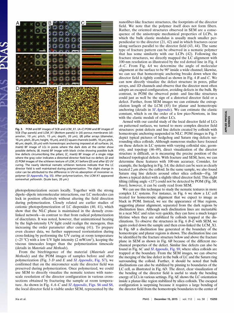
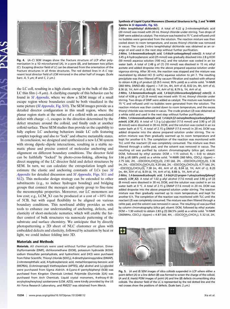
Methods) and the POM images of samples before and afterpolymerization (Fig. 3 D and E and SI Appendix, Fig. S7), weconfirmed that on the micrometer scale the director field waspreserved during polymerization. Once polymerized, we coulduse SEM to directly visualize the nematic texture with nano-scale resolution of the director configuration in various cross-sections obtained by fracturing the sample at room tempera-ture. As shown in Fig. 4 A–C and SI Appendix, Figs. S6 and S8,the local director field is visible under SEM, represented by the
nanofiber-like fracture structures, the footprints of the directorfield. We note that the polymer itself does not form fibers.Rather, the oriented structures observed in SEM are a conse-quence of the anisotropic mechanical properties of LCPs, inwhich the bulk elastic modulus is usually much smaller per-pendicular to the director (21, 42) and in which fractures occuralong surfaces parallel to the director field (43, 44). The sametype of fracture pattern can be observed in a nematic polymerthat has some similarity with our LCPs (42). Following thefracture structures, we directly mapped the LC alignment with100-nm resolution as illustrated by the red dotted line in Fig. 4A–C. From Fig. 4A we determine the angle of molecularalignment at the surface to be 90° inside a wide channel; likewise,we can see that homeotropic anchoring breaks down when thedirector field is tightly confined as shown in Fig. 4 B and C. Wecan now directly visualize the defect structure in pores, pillararrays, and 1D channels and observe that the director most oftenadopts an escaped configuration, avoiding defects in the bulk. Bycontrast, in POM the observed point- and line-like structurescould just as well be the sign of a distorted director field or adefect. Further, from SEM images we can estimate the extrap-olation length of the LCM (45) for planar and homeotropicanchoring (details in SI Appendix). We can estimate the elasticconstant, which is on the order of a few pico-Newtons, in linewith the elastic moduli of other LCs.Armed with our careful study of the local director field of LCs
on patterned surfaces, we turned to more complex director fieldstructures: point defects and line defects created by colloids withhomeotropic anchoring suspended in NLC. POM images in Fig. 5depict typical pictures of hedgehog and Saturn ring defects sur-rounding silica colloids. Although numerous studies have focusedon these defects in LC systems with varying colloidal size, geom-etry, and topology (46–49), direct visualization of the directorstructure is difficult, as is measuring the precise position of theinduced topological defects. With fracture and SEM, here, we candetermine these features with 100-nm accuracy. Consider, forexample, the hedgehog in Fig. 5A; the defect can be seen as clearlylocated 2 μm above the colloid. In the same sample, we also foundSaturn ring line defects around other silica colloids—Fig. 5Bshows a typical defect with a slightly tilted director field. This slighttilting (tilting angle <15°) could not be detected by POM (Fig. 5B,Inset); however, it can be easily read from SEM.We can use this technique to study the nematic textures in more
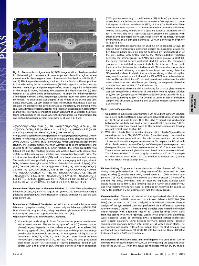
complex LC systems. For instance, in Fig. 6 we show a LC celltreated for homeotropic alignment that we expect to image asblack in POM. Instead, we see the appearance of blue regions,suggesting planar alignment, separated from the dark regions bydisclination lines. Although such disclination lines are metastablein a neat NLC and relax very quickly, they can have a much longerlifetime when they are stabilized by colloids trapped at the dis-clinations. To observe the structures in Fig. 6 B–E with SEM, weagain cooled down the sample and then cross-linked the LCM_X1.In Fig. 6B a disclination line generated at the boundary of thehomeotropic and planar regions is shown. The disclination line canbe identified by the fracture structure below and above the fractureplane in SEM as shown in Fig. 6B because of the different me-chanical properties of the defect. Similar line defects can also befound in Fig. 6C and SI Appendix, Fig. S9, where silica colloids aretrapped at the boundary. From the SEM images, we can observethe merging of the line defect in the bulk of LC and the Saturn ringsurrounding the colloid. Further, it should be noted that bulkdisclinations can also be stabilized by pinning to boundaries of theLC cell, as illustrated in Fig. 6D. The direct, clear visualization ofthe bending of the director field is useful to study the bendingenergy of LCs in various settings. Fig. 6E shows the LC orientationinside a planar-like region stabilized by silica colloids. The escapedconfiguration is surprising because it requires a large bending ofthe director field from the homeotropic boundaries to the center of
Fig. 3. POM and BF images of 5CB and LCM_X1. (A–C) POM and BF images of5CB (Top panels) and LCM_X1 (Bottom panels) in (A) porous membranes (di-ameter, 10 μm; pitch, 15 μm; depth, 20 μm), (B) pillar arrays (diameter,10 μm; pitch, 20 μm; height, 19 μm), and (C) square channels (width, 10 μm; pitch,40 μm; depth, 20 μm) with homeotropic anchoring imposed at all surfaces. (A,Insets) BF image of LCs in pores where the dark dots at the center showpossible defects; (B, Insets) BF image with black circles showing possible bulkline defects circumscribing the pillars; (C, Insets) BF image of a single ridgewhere the gray color indicates a distorted director field but no defect; (D andE) POM images of the schlieren texture of LCM_X1 before (D) and after (E) UVcuring. The nearly identical nematic schlieren textures indicate that the LCdirector field is well maintained during polymerization. The slight change incolor can be attributed to the difference in UV-vis absorption of monomer vs.polymer (SI Appendix, Fig. S5). After polymerization, the LCM-X1 appearedsomewhat yellowish. (Scale bars, 20 μm.)
Xia et al. PNAS | December 15, 2015 | vol. 112 | no. 50 | 15293
the LC cell, resulting in a high elastic energy in the bulk of this 2DLC thin film (∼8 μm). A clarifying example of this behavior can befound in SI Appendix, where we show a SEM image of a smallescape region whose boundaries could be both visualized in thesame picture (SI Appendix, Fig. S10). The SEM images provide us adetailed director configuration in this small region, where theplanar region starts at the surface of a colloid with an associateddefect with charge −1, escapes in the direction determined by thedefect structure around the colloid, and finally ends at anothercolloid surface. These SEM studies thus provide us the capability tofully explore LC anchoring behaviors inside LC cells featuringcomplex topology and also to “lock” and observe metastable states.In conclusion, we designed and synthesized a new LCM system
with strong dipole–dipole interactions, resulting in a stable ne-matic phase and precise control of molecular anchoring andalignment on different boundary conditions. The director fieldcan be faithfully “locked” by photo-cross-linking, allowing fordirect mapping of the LC director field and defect structures bySEM. In turn, we can calculate the extrapolation length andestimate the elastic and anchoring constants of LCs (see SIAppendix for detailed discussion and SI Appendix, Figs. S11 andS12). This molecular design strategy can be extended to othersubstituents (e.g., to induce hydrogen bonding) and bridginggroups that connect the mesogen and epoxy group to fine-tunethe mesomorphic properties. Moreover, our LC monomers arelow cost; e.g., LCM_X1 can be produced at a cost of ∼10% thatof 5CB, but with equal flexibility to be aligned on variousboundary conditions. This newfound ability provides us withtools to enhance our understanding of anchoring, defects, andelasticity of short-molecule nematics, which will enable the fur-ther control of bulk structures via nanoscale patterning of thesubstrate and surface chemistry. We anticipate that by directlyphotopatterning a 2D sheet of NLC elastomer or glass withembedded defects and elasticity, followed by actuation by heat orlight, we could induce folding into 3D.
Materials and MethodsMaterials. All chemicals were used without further purification. Dime-thylformamide (DMF), dichloromethane (DCM), potassium hydroxide (KOH),sodium thiosulfate pentahydrate, and hydrochloric acid (HCl) were purchasedfrom Fisher Scientific. Thionyl chloride (SOCl2), 4-dimethylaminopyridine (DMAP),2-nitroterephthalic acid, 4-hydroxybenzoic acid, metachloroperoxy-benzoic acid(MCPBA), (3-Aminopropyl) triethoxysilane (APTES), allyl alcohol and (±)-glycidolwere purchased from Sigma Aldrich. 4-Cyano-4′-pentylbiphenyl (5CB) waspurchased from Kingston Chemicals Limited. Polyimide (Durimide 32A) waspurchased from Arch Chemicals. Liquid crystal monomers, 4-ethoxy-4′-(6-acryloyloxyhexyloxy) azobenzene (LCM_AZO), were kindly provided by the USAir Force Research Laboratory, and RM257 was obtained from Merck.
Synthesis of Liquid Crystal Monomers (Chemical Structures in Fig. 2 and 1H-NMRSpectra in SI Appendix, Fig. S2).2-Nitro terephthaloyl dichloride(1). A total of 4.22 g 2-nitroterephthalic acid(20 mmol) was mixed with 20 mL thionyl chloride under stirring. Two drops ofDMFwere added as catalyst. Themixturewas heated to 75 °C and refluxed untilno bubbles were generated from the solution. The reaction mixture was thencooled down to room temperature, and excess thionyl chloride was removedin vacuo. The crude 2-nitro terephthaloyl dichloride was obtained as an or-ange oil and used in the next step without further purification.2-Nitro, 1,4-benzenedicarboxylic acid, 1,4-bis(4-carboxyphenyl) ester(2). A total of3.45 g 4-hydroxybenzoic acid (25 mmol) was gradually dissolved into 2.8 g KOH(50 mmol) aqueous solution (100 mL), and the solution was cooled in an icewater bath. A total of 2.48 g of (1) (10 mmol) was dissolved in 15 mL ethylacetate and added dropwise into the above prepared aqueous solution undervigorous stirring. After 30 min, the reaction was stopped and the mixture wasneutralized by diluted HCl (5 vol%) aqueous solution to pH 7. The resultingprecipitate was then filtered off by vacuum filtration and washed with ethanolto obtain 4.28 g of product (2) (9.5 mmol, 95% yield) as a white solid. 1H-NMR(360 MHz, DMSO-d6): δ(ppm) = 7.41 (m, 4H, ArH of d), 8.02 (m, 4H, ArH of e),8.36 (d, 1H, ArH of c), 8.65 (d, 1H, ArH of b), 8.79 (s, 1H, ArH of a).2-Nitro, 1,4-benzenedicarboxylic acid, 1,4-bis[4-(chlorocarbonyl)phenyl] ester(3). Atotal of 4.06 g of (2) (9 mmol) was mixed with 15 mL thionyl chloride understirring. Two drops of DMF were added as catalyst. The mixture was heated to75 °C and refluxed until no bubbles were generated from the solution. Thereaction mixture was then cooled down to room temperature, and the excessthionyl chloride was removed in vacuo. The crude product (3) was obtained asa white solid and used in the next step without further purification.2-Nitro, 1,4-benzenedicarboxylic acid, 1,4-bis[4-[(2-oxiranylmethoxy)carbonyl]phenyl]ester(4, LCM_X1). A total of 1.3 g (±)-glycidol (17.6 mmol) and 3.90 g of (3)(8 mmol) were dissolved in 30 mL DCM, and the solution was cooled in an icewater bath at 0 °C. A total of 2.15 g DMAP (17.6 mmol) in 20 mL DCM wasadded dropwise into the above prepared solution under stirring. The re-action mixture was then gradually warmed up to room temperature andkept for another 6 h. The completion of the reaction was monitored withTLC until the reactant (3) was completely consumed. The mixture was thenfiltered through a celite pad, and the solvent was removed in vacuo. Theresulting oil was purified by column chromatography (silica gel; eluent:DCM, followed by ethyl acetate: DCM = 1:15 vol/vol; Rf ∼ 0.4) to obtain3.06 g (4) (68% yield) as a white solid. 1H-NMR (360 MHz, CDCl3): δ(ppm) =2.75 (dd, 2H, −(O)COCH2CHCH2O), 2.93 (dd, 2H, −(O)COCH2CHCH2O), 3.36(m, 2H, −(O)COCH2CHCH2O), 4.20 (dd, 2H, −(O)COCH2CHCH2O), 4.71 (dd, 2H,−(O)COCH2CHCH2O), 7.38 (m, 4H, ArH of d), 8.04 (d, 1H, ArH of c), 8.20(m, 4H, ArH of e), 8.59 (d, 1H, ArH of b), 8.88 (s, 1H, ArH of a).2-Nitro, 1,4-benzenedicarboxylic acid, 1,4-bis[4-[(2-propen-1-yloxy)carbonyl]phenyl]ester(5, LCM_X2). A total of 1.02 g allyl alcohol (17.6 mmol) and 3.90 g of (3)(8 mmol) were dissolved in 30 mL DCM, and the solution was cooled in an icewater bath at 0 °C. A total of 2.15 g DMAP (17.6 mmol) in 20 mL DCM wasadded dropwise into the above prepared solution under stirring. The reactionmixture was then gradually warmed up to room temperature and kept foranother 6 h. The completion of the reaction was monitored with TLC until thereactant (3) was completely consumed. The mixture was then filtered through acelite pad, and the solvent was removed in vacuo. The resulting oil was purifiedby column chromatography (silica gel; eluent: DCM, followed by ethyl acetate:DCM = 1:30 vol/vol) to obtain 2.83 g (5) (66.5% yield) as a white solid. 1H-NMR(360MHz, CDCl3): δ(ppm) = 4.87 (dd, 4H, −(O)COCH2CHCH2), 5.32 (d, 2H,
Fig. 4. (A–C) SEM images show the fracture structure of LCP after poly-merization in a 1D microchannel (A), in a pore (B), and between two pillars(C). Escaping director field of LC can be observed from the orientation of thefracture structures in all three structures. The red dotted lines in A–C rep-resent local director field of LCM mirrored in the other half of images. (Scalebars: A, 5 μm; B and C, 2 μm.)
Fig. 5. (A and B) SEM images of silica colloids suspended in LCP where either apoint defect (A) or a line defect (B) was formed to screen the charge of the colloid.(A and B, Insets) POM images of point (A) and line (B) defects circumscribing silicacolloids. The director field of the LC is represented by the red dotted line and thered crosses show the positions of defects. (Scale bars: 2 μm.)
15294 | www.pnas.org/cgi/doi/10.1073/pnas.1513348112 Xia et al.
− (O)COCH2CHCH2), 5.44 (d, 2H, − (O)COCH2CHCH2), 6.06 (m, 2H,−(O)COCH2CHCH2), 7.37 (m, 4H, ArH of d′), 8.04 (d, 1H, ArH of c′), 8.20 (m, 4H,ArH of e′), 8.60 (d, 1H, ArH of b′), 8.88 (s, 1H, ArH of a′).4-(4-(((Oxiran-2-yl)methoxy)carbonyl)phenyl) 1-(4-((allyloxy)carbonyl)phenyl) 2-nitro-benzene -1,4-dioate (6, LCM_X3). A total of 6.8 g (12.8 mmol) of (5) was dissolved in30mL DCMat 0 °C. A total of 3.31 gMCPBA (20mmol) was gradually added to thesolution. The reaction mixture was then warmed up to room temperature andallowed to stir for additional 48 h. After reaction, the white precipitate wasfiltered off and the resulting solution was washed twice with sodium thio-sulfate pentahydrate aqueous solution and then washed twice with brine. Thesolution was then dried with MgSO4 and the solvent was removed in vacuo.The crude solid was purified by column chromatography (silica gel; eluent,DCM, followed by ethyl acetate: DCM = 1:30 vol/vol) to obtain 2.1g (6) (30%yield). 1H-NMR (360MHz, CDCl3): δ(ppm) = 2.75 (dd, 1H, −(O)COCH2CHCH2O),2.93 (dd, 1H, −(O)COCH2CHCH2O), 3.36 (m, 1H, −(O)COCH2CHCH2O), 4.20 (dd,1H, −(O)COCH2CHCH2O), 4.71 (dd, 1H, −(O)COCH2CHCH2O), 4.87 (dd, 2H,−(O)COCH2CHCH2), 5.32 (d, 1H, −(O)COCH2CHCH2), 5.44 (d, 1H, −(O)COCH2CHCH2),6.06 (m, 1H, −(O)COCH2CHCH2),7.38 (m, 4H, ArH of d′′), 8.04 (d, 1H, ArH of c′′),8.20 (m, 4H, ArH of e′′), 8.59 (d, 1H, ArH of b′′), 8.88 (s, 1H, ArH of a′′).
Preparation of Liquid Crystal Monomer Solutions. A total of 200mg liquid crystalmonomer (4, LCM_X1) and 4 mg Iragcure 261 (2 wt%; Ciba Specialty Chemicals) asphotoacid generator (PAG)were dissolved in 10 gDCMand kept in a cool and darkplace before use.
Fabrication of Patterned Substrates. All of the patterned substrates werefabricated by replica molding from commercially available epoxy (D.E.R. 354;Dow Chemical) on glass slides, using poly(dimethylsiloxane) (PDMS) molds,following the procedure reported in the literature (50).Preparation of substrates with desired LC anchoring.
i) Homeotropic anchoring of LCs on flat substrates, porous membranes,and square channels. The anchoring type of the LC (homeotropic orplanar) largely depends on the surface energy of the interface (51).For many types of LCMs, hydrophilic surfaces with high surface energyusually give homeotropic anchoring. In our system, all liquid crystalmonomers, LCM_X1, LCM_X2, and LCM_X3, were found to havehomeotropic anchoring on a SiO2 surface. Here, we used precleanedglass slides as the flat substrates or coated patterned polymer sub-strates with a thin layer of SiO2 through a chemical vapor deposition
(CVD) process according to the literature (52). In brief, patterned sub-strates kept in a desiccator under vacuum were first exposed to chem-ical vapors of silicon tetrachloride (SiCl4, 0.2 mL) for 10–15 min. Thenthe samples were exposed to a humidity chamber (humidity ∼90%) for10 min, followed by immersion in a pyridine aqueous solution (3 vol%)for 5–10 min. The final substrates were obtained by washing withethanol and deionized (DI) water, respectively, three times, followedby drying by an air gun and baking at 100 °C in a convection oven for15 min to 1 h.
ii) Strong homeotropic anchoring of LCM_X1 on micropillar arrays. Toachieve high homeotropic anchoring energy on micropillar arrays, wefirst treated pillars based on step (i), followed by functionalization ofthe SiO2 surface with APTES. Due to the Michael-addition reactionsbetween the amino groups in APTES and epoxy groups in LCM_X1,the newly formed surface anchored LCM_X1, where the mesogenicgroups were orientated perpendicularly to the interface. As a result,the interaction between the interface and LCM molecules was substan-tially increased, showing stronger homeotropic anchoring than theSiO2-coated surface. In detail, the sample consisting of the micropillararray was immersed in a solution of 1 vol% APTES in an ethanol/watermixture (90:10 vol/vol) for ∼10 min and then rinsed with ethanol and DIwater three times and dried by air gun. Finally, the sample was baked ina convection oven at 100 °C for 15 min to 1 h.
iii) Planar anchoring. To create planar anchoring for LCMs, a glass substratewas spin coated with a thin layer of polyimide from its xylene solutionat 5,000 rpm (on spin coater WS-650Hzb-23NPP-UD-3; Laurell) for 30 s,followed by baking at 130 °C for 20 min. A uniform planar anchoringsample was obtained by rubbing the polyimide-coated substrate witha velvet cloth.
Liquid crystal cell preparation.
i) On patterned substrates. Approximately 20–40 μL LCM_X1/DCM solutionwas placed on the patterned substrate, and solvent DCMwas evaporatedat 130 °C for at least 10 min. Then the LCM_X1 liquid was sandwichedbetween the substrate and another cover glass (treat if needed) at 130 °C.The sample was then cooled down to the desired temperature (coolingrate not critical here) to align LC.
ii) With silica colloids. Five-micrometer diameter silica colloids (Sigma Aldrich)were dispersed in a LCM_X1/DCM solution (note that a high concentrationof ∼20 wt% was preferred), and the mixture was sonicated for at least15 min to obtain a homogeneous suspension. To prepare the LC cell withsilica colloids, several drops (∼20–40 μL) of the suspension were placed on aclean glass slide, and the solvent was evaporated at 130 °C for at least 10 min.Then another precleaned glass slide was placed on top to make a LC cell.The thickness of the LC cell was roughly controlled as ∼10 μm. The samplewas then cooled down from 130 °C to the desired temperature (coolingrate not critical here) to align the LC.
UV Cross-Linking. To prevent the reorientation of the directors of LCM_X1during photopolymerization, UV curing was carefully performed in threesteps, including (i) samples were slowly cooled down at 1 °C/min to room tem-perature (∼25 °C); (ii) samples were exposed to a low UV power (∼2 mW/cm2 at365 nm, Hg lamp), overnight; and (iii) after UV exposure, samples wereslowly heated up to 100 °C at a ramping rate of 1 °C/min on a Mettler FP82and FP90 thermo-system hot stage in ambient air, followed by baking at120 °C for another 1–2 h to completely cure the epoxy groups.
Characterization. Chemical structures of the synthesized chemicals wereconfirmed with 1H-NMR performed on a Bruker Advance DMX 360 (360MHz) spectrometer at 25 °C and analyzed with TOPSPIN software. Thermoanalysis of the synthesized LCMs was performed on a differential scanningcalorimetry (DSC) Q2000 (TA Instruments). Samples were heated and cooledunder nitrogen with a ramping rate of 10 °C/min for three cycles. Datafrom the second cycle were reported. Liquid crystal phases and alignmentswere observed under an Olympus BX61 motorized optical microscopewith crossed polarizers, using CellSens software. Liquid crystal polymersamples were manually broken into pieces or cut with a razor blade. Thecross-section was coated with a 4-nm iridium layer for SEM. Imaging wasperformed on a dual-beam FEI Strata DB 235 Focused Ion Beam (FIB)/SEMinstrument with a 5-kV electron beam.
Measurement of Refractive Index and Birefringence. We used Snell’s law toestimate the refractive indexes of LCM_X1 by comparing the apparent thick-ness of the LC cell, DLC, with the actual cell thickness without LC, D0; that is,
Fig. 6. Metastable configurations. (A) POM image of silica colloids suspendedin LCM resulting in coexistence of homeotropic and planar-like regions, wherethe metastable planar regions (blue color) are stabilized by silica colloids. (B, C,and E) SEM images characterizing the local director field at different positionsin A as indicated by the red dotted squares. (B) SEM image taken at the boundarybetween homeotropic and planar regions of LC, where a bright line in the middleof the image is shown, indicating the presence of a disclination line. (C) SEMimage of a silica colloid sitting at the boundary. The bright line in the image showsa line defect in the bulk of LC that merged with the Saturn ring defect encirclingthe colloid. The silica colloid was trapped in the middle of the LC cell, and sankslightly downward. (D) SEM image of fiber-like structure that shows a bulk dis-clination line pinned to the bottom surface, as indicated by the bending whiteline. (E) SEM image of local LC director field inside an escaped region. Horizontallyaligned fiber-like fractures indicating planar alignment of LC director field werefound in themiddle of the image, where the bending fiber-like fractures from topand bottom boundaries merged. (Scale bars: A, 20 μm; B–E, 3 μm.)
Xia et al. PNAS | December 15, 2015 | vol. 112 | no. 50 | 15295
APP
LIED
PHYS
ICAL
SCIENCE
S
ne,o = D0/DLC. We prepared a uniform planar cell in the way same as describedearlier. D0 and DLC were measured before and after LC was infiltrated, re-spectively. Accordingly, we obtained the extraordinary refractive index, ne∼1.67 ± 0.02 and the ordinary refractive index, no ∼ 1.5 ± 0.02 of LC when thepolarized light was parallel and perpendicular to the LC director, respectively.The birefringence of LCM_X1 was estimated as ∼0.17. We also estimated bi-refringence of LCM_X1 from a wedge cell, using the Michael–Levy chart be-fore and after UV curing, as 0.16 ± 0.02, in good agreement with that
measured from optical microscopy. Again, the consistent birefringence beforeand after polymerization as shown in Fig. 3 D and E clearly indicates thatpolymerization did not affect the nematic order parameter.
ACKNOWLEDGMENTS. We acknowledge support by the National ScienceFoundation Materials Science and Engineering Center grants to the Univer-sity of Pennsylvania, DMR-1120901, DMR-1410253 (to S.Y.), and DMR12-62047 (to R.D.K.). This work is also partially supported by a SimonsInvestigator grant from the Simons Foundation (to R.D.K.).
1. Higgins DA, Luther BJ (2003) Watching molecules reorient in liquid crystal dropletswith multiphoton-excited fluorescence microscopy. J Chem Phys 119(7):3935–3942.
2. Kachynski AV, Kuzmin AN, Prasad PN, Smalyukh II (2007) Coherent anti-Stokes Ramanscattering polarized microscopy of three-dimensional director structures in liquidcrystals. Appl Phys Lett 91(15):151905.
3. Smalyukh II, Shiyanovskii SV, Lavrentovich OD (2001) Three-dimensional imaging oforientational order by fluorescence confocal polarizing microscopy. Chem Phys Lett336(1–2):88–96.
4. Feller MB, Chen W, Shen YR (1991) Investigation of surface-induced alignment ofliquid-crystal molecules by optical second-harmonic generation. Phys Rev A 43(12):6778–6792.
5. Yelin D, Silberberg Y, Barad Y, Patel JS (1999) Phase-matched third-harmonic gen-eration in a nematic liquid crystal cell. Phys Rev Lett 82(15):3046–3049.
6. Yoon DK, et al. (2007) Internal structure visualization and lithographic use of periodictoroidal holes in liquid crystals. Nat Mater 6(11):866–870.
7. Zhang C, et al. (2012) Direct observation of smectic layers in thermotropic liquidcrystals. Phys Rev Lett 109(10):107802.
8. Gao M, et al. (2014) Direct observation of liquid crystals using cryo-TEM: Specimenpreparation and low-dose imaging. Microsc Res Tech 77(10):754–772.
9. Yoon DK, et al. (2013) Three-dimensional textures and defects of soft materiallayering revealed by thermal sublimation. Proc Natl Acad Sci USA 110(48):19263–19267.
10. Costello MJ, Meiboom S, SammonM (1984) Electron microscopy of a cholesteric liquidcrystal and its blue phase. Phys Rev A 29(5):2957–2959.
11. Livolant F, Bouligand Y (1989) Freeze-fractures in cholesteric mesophases of polymers.Mol Cryst Liq Cryst 166(1):91–100.
12. Bouligand Y (1972) Twisted fibrous arrangements in biological materials and chole-steric mesophases. Tissue Cell 4(2):189–217.
13. Donald AM, Viney C, Windle AH (1983) Banded structures in oriented thermotropicpolymers. Polymer 24(2):155–159.
14. Mitchell GR, Windle AH (1982) Structural analysis of an oriented liquid crystallinecopolyester. Polymer 23(9):1269–1272.
15. Cavallaro M, Jr, et al. (2013) Exploiting imperfections in the bulk to direct assembly ofsurface colloids. Proc Natl Acad Sci USA 110(47):18804–18808.
16. Bishop DJ, Gammel PL, Huse DA, Murray CA (1992) Magnetic flux-line lattices andvortices in the copper oxide superconductors. Science 255(5041):165–172.
17. Tchernyshyov O, Chern G-W (2005) Fractional vortices and composite domain walls inflat nanomagnets. Phys Rev Lett 95(19):197204.
18. Kibble TWB (1976) Topology of cosmic domains and strings. J Phys Math Gen 9(8):1387.
19. Nikkhou M, et al. (2015) Light-controlled topological charge in a nematic liquidcrystal. Nat Phys 11(2):183–187.
20. Modes CD, Bhattacharya K, Warner M (2010) Disclination-mediated thermo-opticalresponse in nematic glass sheets. Phys Rev E Stat Nonlin Soft Matter Phys 81(6 Pt 1):060701.
21. Ware TH, McConney ME, Wie JJ, Tondiglia VP, White TJ (2015) Actuating materials.Voxelated liquid crystal elastomers. Science 347(6225):982–984.
22. Dierking I (2010) Recent developments in polymer stabilised liquid crystals. PolymChem 1(8):1153–1159.
23. Dierking I, Archer P (2013) Imaging liquid crystal defects. RSC Advances 3(48):26433–26437.
24. Broer DJ, Bastiaansen CMW, Debije MG, Schenning APHJ (2012) Functional organicmaterials based on polymerized liquid-crystal monomers: Supramolecular hydrogen-bonded systems. Angew Chem Int Ed Engl 51(29):7102–7109.
25. Küpfer J, Finkelmann H (1991) Nematic liquid single crystal elastomers. MakromolChem Rapid Commun 12(12):717–726.
26. Ohm C, Brehmer M, Zentel R (2010) Liquid crystalline elastomers as actuators andsensors. Adv Mater 22(31):3366–3387.
27. Thomsen DL, et al. (2001) Liquid crystal elastomers with mechanical properties of amuscle. Macromolecules 34(17):5868–5875.
28. Yu Y, Nakano M, Ikeda T (2003) Photomechanics: Directed bending of a polymer filmby light. Nature 425(6954):145–145.
29. Warner M, Terentjev EM (2003) Liquid Crystal Elastomers (Clarendon, Oxford).30. Broer DJ, Crawford GP, Zumer S (2011) Cross-Linked Liquid Crystalline Systems: From
Rigid Polymer Networks to Elastomers (CRC, New York).31. Petrov VF, Shimizu Y (2001) Nitro substitution in achiral calamitic liquid crystals. Liq
Cryst 28(11):1627–1647.32. Dewar MJS, Goldberg RS (1970) Effects of central and terminal groups on nematic
mesophase stability. J Org Chem 35(8):2711–2715.33. Lee JY, Jang J, Hong SM, Hwang SS, Kim KU (1999) Relationship between the struc-
ture of the bridging group and curing of liquid crystalline epoxy resins. Polymer40(11):3197–3202.
34. Minkin VI, Osipov OA, Zhdanov YA (1970) Dipole Moments in Organic Chemistry(Plenum, New York).
35. Zuev VV, de Vekki DA (2006) Catalytic isomerization of terminal olefins in liquid-crystalline polyesters at hydrosilylation with 1-(1′-arylethoxy)-1,1,3,3-tetramethyldi-siloxanes. Russ J Org Chem 42(8):1105–1112.
36. Faetti S (1998) The effects of curvature on nematic liquid crystals confined in a cy-lindrical cavity. Phys Lett A 237(4–5):264–270.
37. Crawford GP, Allender DW, Doane JW (1992) Surface elastic and molecular-anchoringproperties of nematic liquid crystals confined to cylindrical cavities. Phys Rev A 45(12):8693–8708.
38. Shaw JM, Gelorme JD, LaBianca NC, Conley WE, Holmes SJ (1997) Negative photo-resists for optical lithography. IBM J Res Dev 41(1.2):81–94.
39. Ito H (1997) Chemical amplification resists: History and development within IBM. IBMJ Res Develop 41(1–2):69–80.
40. Broer DJ, Lub J, Mol GN (1993) Synthesis and photopolymerization of a liquid-crys-talline diepoxide. Macromolecules 26(6):1244–1247.
41. Jahromi S, Lub J, Mol GN (1994) Synthesis and photoinitiated polymerization of liquidcrystalline diepoxides. Polymer 35(3):622–629.
42. van Oosten CL, Bastiaansen CWM, Broer DJ (2009) Printed artificial cilia from liquid-crystal network actuators modularly driven by light. Nat Mater 8(8):677–682.
43. Berreman DW, Meiboom S, Zasadzinski JA, Sammon MJ (1986) Theory and simulationof freeze-fracture in cholesteric liquid crystals. Phys Rev Lett 57(14):1737–1740.
44. Zasadzinski JA, Bailey SM (1989) Applications of freeze-fracture replication to prob-lems in materials and colloid science. J Electron Microsc Tech 13(4):309–334.
45. Hudson SD, Thomas EL (1989) Frank elastic-constant anisotropy measured fromtransmission-electron-microscope images of disclinations. Phys Rev Lett 62(17):1993–1996.
47. Senyuk B, et al. (2013) Topological colloids. Nature 493(7431):200–205.48. Poulin P, Stark H, Lubensky TC, Weitz DA (1997) Novel colloidal interactions in an-
isotropic fluids. Science 275(5307):1770–1773.49. Muševic I, �Skarabot M, Tkalec U, Ravnik M, Žumer S (2006) Two-dimensional nematic
colloidal crystals self-assembled by topological defects. Science 313(5789):954–958.50. Zhang Y, Lo C-W, Taylor JA, Yang S (2006) Replica molding of high-aspect-ratio
polymeric nanopillar arrays with high fidelity. Langmuir 22(20):8595–8601.51. Warenghem M (1982) A test for surface energy anisotropy sign determination. Mol
Cryst Liq Cryst 89(1–4):15–21.52. Klaus JW, George SM (2000) SiO2 chemical vapor deposition at room temperature
using SiCl4 and H2O with an NH3 catalyst. J Electrochem Soc 47(7):2658–2664.
15296 | www.pnas.org/cgi/doi/10.1073/pnas.1513348112 Xia et al.