Direct numerical simulation and control of the flow over a backward facing ramp Ch-H. Bruneau, M.Jedouaa, K.Khadra, I. Mortazavi 2 1 IMB Université de Bordeaux, France 2 IMB Institut polytechnique de Bordeaux,France Inria Bordeaux Sud Ouest MC2 project 3rd GDR “Contrôle des décollements”Symposium
Transcript
Direct numerical simulation and control ofthe flow over a backward facing ramp
Ch-H. Bruneau, M.Jedouaa, K.Khadra, I. Mortazavi2
1IMB Université de Bordeaux, France
2IMB Institut polytechnique de Bordeaux,France
Inria Bordeaux Sud Ouest MC2 project
3rd GDR “Contrôle des décollements”Symposium
Numericalsimulation and
control of the flowover a backward
facing ramp
Ch-H. Bruneau,M.Jedouaa,K.Khadra,
I. Mortazavi
Motivations
Computationaldomain andnumerical tools
Analysis of theuncontrolled flow
Active control
Conclusion
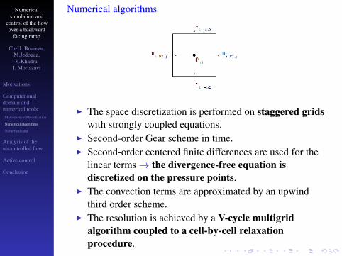
Outline
Motivations
Computational domain and numerical tools
Analysis of the uncontrolled flow
Active control
Conclusion
Numericalsimulation and
control of the flowover a backward
facing ramp
Ch-H. Bruneau,M.Jedouaa,K.Khadra,
I. Mortazavi
Motivations
Computationaldomain andnumerical tools
Analysis of theuncontrolled flow
Active control
Conclusion
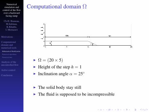
Motivations
On a ground vehicle the rear window is responsible for:
• 30 to 45 % of the total vehicle drag→ Real impact on fuel consumption and CO2 emission.
I Focus on the recirculation zone behind a car rear-windowusing a two -dimensional backward facing ramp which is abenchmark of GDR “Contrôle des décollements”
Aim of the study :
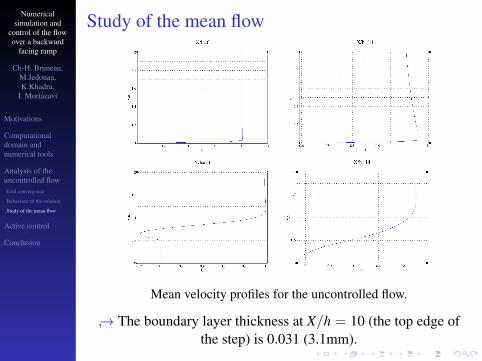
I Simulation and analysis of the flow behaviour over thebackward facing ramp
• The frequency of the jet f = 20Hz (similar results with50Hz)
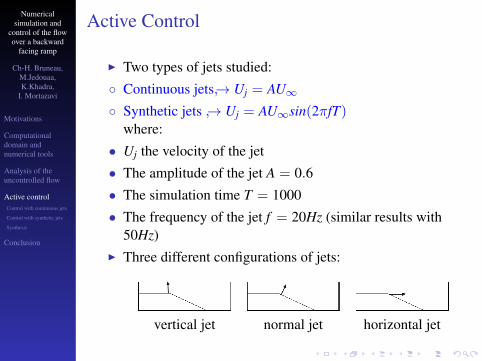
I Three different configurations of jets:
vertical jet normal jet horizontal jet
Numericalsimulation and
control of the flowover a backward
facing ramp
Ch-H. Bruneau,M.Jedouaa,K.Khadra,
I. Mortazavi
Motivations
Computationaldomain andnumerical tools
Analysis of theuncontrolled flow
Active controlControl with continuous jets
Control with synthetic jets
Synthesis
Conclusion
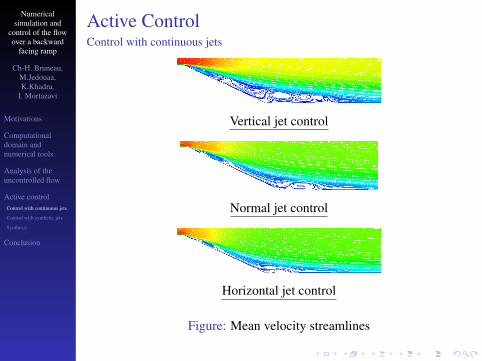
Active ControlControl with continuous jets
Vertical jet control
Normal jet control
Horizontal jet control
Figure: Mean velocity streamlines
Numericalsimulation and
control of the flowover a backward
facing ramp
Ch-H. Bruneau,M.Jedouaa,K.Khadra,
I. Mortazavi
Motivations
Computationaldomain andnumerical tools
Analysis of theuncontrolled flow
Active controlControl with continuous jets
Control with synthetic jets
Synthesis
Conclusion
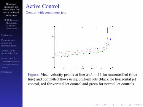
Active ControlControl with continuous jets
Figure: Mean velocity profile at line X/h = 11 for uncontrolled (blueline) and controlled flows using uniform jets (black for horizontal jetcontrol, red for vertical jet control and green for normal jet control).
Numericalsimulation and
control of the flowover a backward
facing ramp
Ch-H. Bruneau,M.Jedouaa,K.Khadra,
I. Mortazavi
Motivations
Computationaldomain andnumerical tools
Analysis of theuncontrolled flow
Active controlControl with continuous jets
Control with synthetic jets
Synthesis
Conclusion
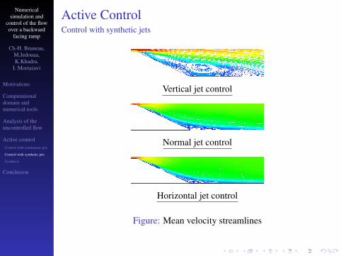
Active ControlControl with synthetic jets
Vertical jet control
Normal jet control
Horizontal jet control
Figure: Mean velocity streamlines
Numericalsimulation and
control of the flowover a backward
facing ramp
Ch-H. Bruneau,M.Jedouaa,K.Khadra,
I. Mortazavi
Motivations
Computationaldomain andnumerical tools
Analysis of theuncontrolled flow
Active controlControl with continuous jets
Control with synthetic jets
Synthesis
Conclusion
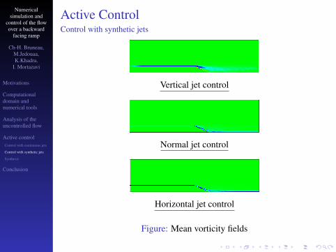
Active ControlControl with synthetic jets
Vertical jet control
Normal jet control
Horizontal jet control
Figure: Mean vorticity fields
Numericalsimulation and
control of the flowover a backward
facing ramp
Ch-H. Bruneau,M.Jedouaa,K.Khadra,
I. Mortazavi
Motivations
Computationaldomain andnumerical tools
Analysis of theuncontrolled flow
Active controlControl with continuous jets
Control with synthetic jets
Synthesis
Conclusion
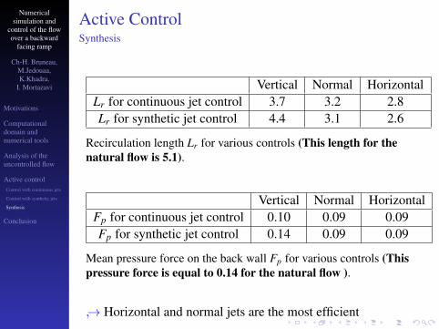
Active ControlSynthesis
Vertical Normal HorizontalLr for continuous jet control 3.7 3.2 2.8Lr for synthetic jet control 4.4 3.1 2.6
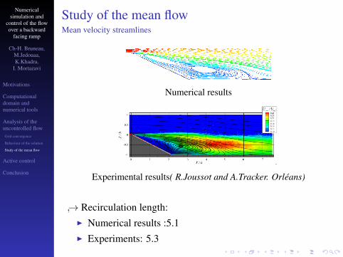
Recirculation length Lr for various controls (This length for thenatural flow is 5.1).
Vertical Normal HorizontalFp for continuous jet control 0.10 0.09 0.09Fp for synthetic jet control 0.14 0.09 0.09
Mean pressure force on the back wall Fp for various controls (Thispressure force is equal to 0.14 for the natural flow ).
→ Horizontal and normal jets are the most efficient
Numericalsimulation and
control of the flowover a backward
facing ramp
Ch-H. Bruneau,M.Jedouaa,K.Khadra,
I. Mortazavi
Motivations
Computationaldomain andnumerical tools
Analysis of theuncontrolled flow
Active control
Conclusion
Outline
Motivations
Computational domain and numerical tools
Analysis of the uncontrolled flow
Active control
Conclusion
Numericalsimulation and
control of the flowover a backward
facing ramp
Ch-H. Bruneau,M.Jedouaa,K.Khadra,
I. Mortazavi
Motivations
Computationaldomain andnumerical tools
Analysis of theuncontrolled flow
Active control
Conclusion
ConclusionI The main characteristics of the uncontrolled flow are well
capturedI Two types of jets studied:
• Continuous jet
• Synthetic jet
→ Similar results except for the vertical jet
I Three different configurations of jet:
• Vertical jet just before the corner
• Normal to the ramp
• Horizontal to the ramp
→ Horizontal and normal jets reduces drastically the size ofthe recirculation zone
Numericalsimulation and
control of the flowover a backward
facing ramp
Ch-H. Bruneau,M.Jedouaa,K.Khadra,
I. Mortazavi
Motivations
Computationaldomain andnumerical tools
Analysis of theuncontrolled flow
Active control
Conclusion
Philippe Angot, Charles-Henri Bruneau, Pierre FabrieA penalization method to take into account obstacles inincompressible viscous flowsNumerische Mathematik,1999
C.H. Bruneau, P. Gillieron ,I. MortazaviFlow manipulation around the Ahmed body with a rearwindow using passive strategiesCompte Rendu Acad. des Sciences, 2007
Charles-Henri Bruneau, Emmanuel Creuse, DelphineDepeyras, Patrick Gillieron, Iraj MortazaviActive procedures to control the flow past the Ahmed bodywith a 25 rear windowInt. J. of Aerodynamics,2011