BEFORE THE FLORIDA PUBLIC SERVICE COMMISSION In Re: Application for increase in water and wastewater rates in Charlotte, Highlands, Lake, Lee, Marion, Orange, Pasco, Pinellas, Polk and Seminole Counties by Utilities, Inc. of Florida / / / / / Docket No. 160101-WS FILED: March 6, 2017 DIRECT TESTIMONY OF ANDREW T. WOODCOCK ON BEHALF OF THE CITIZENS OF THE STATE OF FLORIDA J. R. Kelly Public Counsel Erik L. Sayler Associate Public Counsel Office of Public Counsel c/o The Florida Legislature 111 West Madison Street, Room 812 Tallahassee, FL 32399-1400 (850) 488-9330 Attorneys for the Citizens of the State of Florida
Transcript
BEFORE THE FLORIDA PUBLIC SERVICE COMMISSION
In Re: Application for increase in water and wastewater rates in Charlotte, Highlands, Lake, Lee, Marion, Orange, Pasco, Pinellas, Polk and Seminole Counties by Utilities, Inc. of Florida
/ / / / /
Docket No. 160101-WS FILED: March 6, 2017
DIRECT TESTIMONY
OF
ANDREW T. WOODCOCK
ON BEHALF OF THE CITIZENS OF THE STATE OF FLORIDA
J. R. Kelly Public Counsel Erik L. Sayler Associate Public Counsel Office of Public Counsel c/o The Florida Legislature 111 West Madison Street, Room 812 Tallahassee, FL 32399-1400 (850) 488-9330 Attorneys for the Citizens of the State of Florida
ERCs not built as of December 31, 2016. To ensure that current customers do not pay 7
for 322 ERCs that will never be used, the total 847 prepaid ERCs not built should be 8
reduced to 525 prepaid ERCs not built (847 less 322). However, I do not recommend 9
that any prepaid commitments be included in the U&U calculation. 10
11
Q. WHAT OTHER CONCERNS DO YOU HAVE REGARDING UIF’S USE OF 12
PREPAIDS IN THE SANDALHAVEN U&U ANALYSIS? 13
A. UIF uses an unreasonable gpd/ERC wastewater generation rate in its U&U calculation. 14
UIF’s U&U calculation uses a 190 gpd/ERC wastewater generation rate which is 15
almost double the average historical rate of 101 gpd/ERC for Sandalhaven. In 16
response to OPC Interrogatory No. 219 (revised), UIF updates “ERCs not built” and 17
“Prepaid Capacity Not Used” on MFR schedule F-6 page 4 of 4. The update reduces 18
prepaid connections to 847 ERCs not built and Prepaid Capacity Not Used to 160,930 19
gpd of wastewater flow. However, this update does not account for the 322 ERCs that 20
will never connect and does not use the appropriate wastewater generation rate of 101 21
gpd/ERC. If both were updated, the Prepaid Capacity Not Used would be reduced 22
further to 53,025 gpd (101 gpd x 525 ERCs not built). In my opinion, using prepaid 23
26
connections in a U&U analysis is inappropriate, but if included, the appropriate 1
wastewater flows associated with the prepaids is 53,025 gpd, which results in a 2
substantially smaller U&U percentage for Sandalhaven. 3
4
Q. WHAT OTHER CONCERNS DO YOU HAVE REGARDING UIF’S 5
SANDALHAVEN U&U ANALYSIS? 6
A. As in previous rate cases, UIF claimed “economies of scale” as a justification for a 7
100% U&U analysis of this system. While I agree in principle that there is the 8
potential for economies of scale in utility construction, the mere mention of the 9
concept is not sufficient evidence to support a 100% U&U value. It is important to 10
note that constructing larger than needed facilities adds to the operations and 11
maintenance costs of a utility which could in turn lead to higher rates. Any 12
consideration of economies of scale in the context of U&U should include specific, 13
measurable advantages, with offsets for corresponding increases in costs related to the 14
extra capacity of the utility. UIF has not provided specific evidence to document the 15
level of economies of scale associated with these facilities, and this argument should 16
be disregarded. 17
18
Q. WHAT HAS THE COMMISSION’S POSITION BEEN HISTORICALLY 19
REGARDING ECONOMIES OF SCALE IN THE U&U CALCULATION? 20
A. In Order No. PSC-16-0013-PAA-SU, the Commission recognized UIF’s argument for 21
economies of scale in prudently sizing the facilities to meet the long term needs of the 22
service area. However, in calculating the U&U for Sandalhaven, there is no mention 23
27
of economies of scale nor is there any U&U adjustment that is attributed to economies 1
of scale. 2
3
Q. HOW WAS THE ECONOMY OF SCALE ISSUE DEALT WITH IN THE 2012 4
RATE CASE BEFORE CHARLOTTE COUNTY? 5
A. There was no U&U adjustment for economies of scale in the Order adopted by 6
Charlotte County. 7
8
Q. CAN YOU DESCRIBE YOUR APPROACH TO THE U&U CALCULATION 9
FOR THE COMPONENTS OF THE SANDALHAVEN SYSTEM? 10
A. My approach to U&U for the Sandalhaven system follows the methodology I used in 11
the 2012 Rate Case under Charlotte County’s jurisdiction which was accepted by the 12
hearing officer and approved by the County Commission. The components I evaluated 13
are the EWD capacity, master lift station, pumping plants, and force main. Each 14
component is associated with providing wastewater service to the customers; however, 15
each has a different capacity and the U&U analysis should account for these 16
differences. Therefore, I evaluated each component separately for U&U which is 17
similar to the approach taken by the Commission in previous Sandalhaven rate cases. 18
See FPSC Order No. PSC-07-0865-PAA-SU and Order No. PSC-16-0013-PAA-SU. 19
In identifying the capacity of these components, I relied upon documentation provided 20
by UIF in previous rate cases including the 2004 Sandalhaven Wastewater Treatment 21
Facility Wastewater Master Plan and two letters. One letter was dated June 26, 2007 22
from CPH, an engineering company, and one letter was dated October 9, 2015 from 23
28
Kimley Horn, another engineering company, both signed by Stephen Romano, a 1
Florida Registered PE (These three documents are included in ATW-15). I also relied 2
upon the prior Sandalhaven Orders issued by the Commission and Charlotte County. 3
Based on my review of these documents, I used the following capacities in my U&U 4
analysis: 5
o Englewood Water District Capacity – 300,000 gpd 6
o Master Lift Station Structure – 665,000 gpd 7
o Pumping Plant – 275,000 gpd 8
o Force Main – 935,000 gpd 9
10
Q, ARE THESE THE SAME CAPACITIES THAT WERE USED BY THE 11
COMMISSION AND CHARLOTTE COUNTY IN PREVIOUS RATE CASES? 12
A. No. The Commission historically has considered the master lift station as having a 13
capacity of 500,000 gpd. However, in referring to the June 26, 2007 letter from CPH 14
Engineers, the engineer states that the master lift station was designed to serve 665,000 15
gpd so I have revised the capacity of the master lift station to equal this design 16
capacity. In addition from the same letter, the installed lift station pumps (pumping 17
plants) have a lower capacity of 275,000 gpd which I have also used. I make the 18
distinction between the lift station pumps and the master lift station to incorporate the 19
lower capacity of the pumps, which in turn increases the pumps’ U&U percentage. 20
21
Since the WWTP has been demolished, the force main to EWD now provides service 22
to the entire Sandalhaven service area. The 2004 Sandalhaven Master Plan identifies 23
29
the projected build out flow for the service area as 935,000 gpd, so I have used that 1
capacity for the force main U&U calculation. 2
3
Q. HOW DO YOU TREAT THE TEST YEAR FLOWS FOR THE 4
SANDALHAVEN U&U CALCULATION? 5
A. According to the flow data presented in Schedule F-2 of the Sandalhaven MFRs, both 6
the WWTP and EWD were receiving wastewater flows through October and a part of 7
November. Since the WWTP was removed from service, the entire wastewater flow 8
generated in the system has been treated by EWD. For my U&U analysis, I utilized 9
the total Test Year flows for the EWD Capacity and the Force Main. For the Master 10
Lift Station and Pumping Plant, I utilized the Test Year flow that was sent to EWD for 11
treatment as a conservative value. 12
13
Q. WHAT ARE THE U&U PERCENTAGES YOU DETERMINED FOR THE 14
SANDALHAVEN SYSTEM COMPONENTS? 15
A. My U&U calculations for the Sandalhaven system components are included in Exhibit 16
ATW-15. The results of the analysis are: 17
o Englewood Water District Capacity – 42.24% U&U 18
o Master Lift Station – 11.27% U&U 19
o Pumping Plant – 27.25% U&U 20
o Force Main – 13.55% U&U 21
30
Q. HOW WOULD YOUR U&U ANALYSIS DIFFER FROM ANALYSIS 1
PROTESTED IN ORDER NO. PSC-16-0013-PAA-SU? 2
A. As I noted before, OPC protested Order No. PSC-16-0013-PAA-SU and the U&U 3
calculation was preserved for determination in this case. I have several concerns with 4
the methodology used for the U&U calculation in that Order. First, the U&U statute 5
and Rule do not mention prepaid or guaranteed revenue connections, thus I would not 6
include prepaid connections and guaranteed revenue connections in the U&U 7
calculation for the reasons stated earlier in this testimony. 8
9
Second, I would not use peaking factors. I believe it was an error to use peaking 10
factors to adjust test year flows used in the U&U calculation which in turn overstated 11
the PAA Order U&U calculation. Both methods of calculating U&U for the 12
Sandalhaven system were substantial deviations from the Commission’s historical 13
method for calculating U&U. 14
15
Q. PLEASE EXPLAIN YOUR CONCERNS REGARDING THE USE OF 16
PEAKING FACTORS IN A U&U CALCULATION? 17
A. Wastewater flows and capacity can be expressed in a number of ways. Frequently 18
with wastewater treatment plants, capacity is expressed in terms of the average annual 19
daily flow, or AADF, which is simply the average of all of the daily flows in a year. 20
Yet, within that year there is also a maximum month (the month with the highest 21
average of daily flows), a maximum day (the day with the highest flow within the 22
year) and even a peak hour (the hour with the highest flow within a day). The 23
31
relationship between these flows is usually expressed as a ratio of the AADF. For 1
example, the maximum daily flow is typically 1.5 to 2 times the annual average daily 2
flow, and peak hour flow is typically 3 to 4 times the annual average daily flow. 3
Expressing the flows for a system in different ways is important for planning, design, 4
and proper sizing. A wastewater pipeline intended to provide service to a 1 MGD 5
AADF service area but will actually be designed to accommodate the peak hour flow 6
of 3 to 4 MGD. When doing a U&U analysis, it is crucial that the basis of flow 7
(AADF, peak hour, maximum day) be the same for both the numerator (the adjusted 8
flow) and the denominator (the facility capacity). 9
10
Q. PLEASE DESCRIBE THE ERROR OF USING PEAKING FACTORS IN THE 11
U&U CALCULATION? 12
A. The test year flows were adjusted by applying a peaking factor of 2.03; however, there 13
was no corresponding adjustment to the facility capacities which are expressed as 14
AADF. As a result, the U&U was calculated by using peak flows divided by AADF 15
capacity. This overstates U&U by a factor of 2.03 times. Therefore, to ensure an 16
apples to apples U&U analysis, the Commission should calculate using AADF flows 17
divided by the AADF capacity in order to arrive at the proper U&U calculation. 18
19
IV. PRO FORMA ADDITIONS TO RATE BASE 20
Q. WILL YOU GENERALLY DESCRIBE THE PRO FORMA ADDITIONS TO 21
RATE BASE? 22
32
A. In this rate case, UIF is requesting approval for approximately $30.8 million in post-1
test year pro forma rate base additions to be included in rate base and customer rates. 2
Of the 47 proposed projects, 44 can be characterized as renewing aging facilities, 3
replacing aging facilities, or improving operations in a number of UIF systems. There 4
are three projects which do not fit into those categories, and they are as follows: (1) 5
The Myrtle Hills Water Main is a growth related project, extending service to new 6
customers in the Sanlando system; (2) Another project is the replacement of a service 7
truck; and (3) The last project is for establishing a UIF system-wide asset database and 8
GIS mapping system. 9
10
Q. HOW DID YOU ORGANIZE YOUR REVIEW OF UIF’s REQUESTED PRO 11
FORMA ADDITIONS TO RATE BASE? 12
A. My review of the requested pro forma projects to rate base fall into four categories or 13
buckets for cost recovery in this rate case: 14
(1) Pro forma projects with adequate cost justification 15
(2) Pro forma projects with cost justification supporting less than requested 16
(3) Pro forma projects lacking adequate cost justification, and 17
(4) Pro forma projects without any cost justification 18
19
Pro forma projects in the first two categories should be included in rate base because 20
the costs appear to be reasonable and were adequately supported by the documentation 21
provided by UIF. Pro forma projects in the second two categories should not be 22
included in rate base for the reasons discussed in my testimony. Throughout my 23
33
testimony I use pro forma projects and pro forma additions synonymously to refer to 1
the almost $30.8 million in post-test year plant additions for which UIF is requesting 2
cost recovery in this rate case. 3
4
Q. DID YOU ENCOUNTER ANY DIFFICULTIES IN PERFORMING YOUR 5
ANALYSIS OF THE AMOUNTS SUPPORTING THE REQUESTED THE 6
PRO FORMA PROJECTS? 7
A. Yes. The amounts requested in the MFRs did not match the amounts supported in Mr. 8
Flynn’s written direct testimony and the supporting documentation in Mr. Flynn’s 9
testimony exhibits did not always add up to the amounts in Mr. Flynn’s written direct 10
testimony. These deficiencies create a huge problem for anyone analyzing the 11
reasonableness of costs because one does not know which amounts the Commission 12
will rely upon when making adjustments or setting prospective rates. In this case, 13
Staff’s Second Set of Interrogatories Nos. 80, 81 and Fourth Set of Interrogatories No. 14
112 recognized this problem by asking why there were discrepancies between 15
Schedule A-3 and Mr. Flynn’s direct testimony and exhibits. The information 16
contained in the MFRs and Mr. Flynn’s testimony should match; however, it does not. 17
UIF stated in each of the interrogatory responses: 18
The values in Schedule A-3 represent the cost information that was 19 available for each project when preparing the MFR’s. Where the values 20 identified for each project contained in witness Flynn’s direct testimony 21 differs from the MFR’s, the difference reflects information gathered 22 subsequently such as project bids, contract amounts, and invoices. The 23 amounts noted in either column do not include capitalized time nor 24 interest incurred during construction 25
34
While I do not agree that UIF should be allowed to provide different information in 1
testimony compared to the information contained in its MFRs, I needed a starting point 2
for my analysis; therefore, I relied on the amounts in Mr. Flynn’s direct testimony for 3
my analysis and recommended adjustments because there were no other data points 4
available. 5
6
Q. WHAT HAS BEEN THE QUALITY OF THE SUPPORTING 7
DOCUMENTATION FOR THE PRO FORMA ADDITIONS TO RATE BASE? 8
A. For the post December 31, 2015 test-year pro forma projects identified in the MFRs, 9
UIF witness Flynn provided only a part of the supporting documentation as Exhibits to 10
his August 30, 2016 testimony. Initially, the MFRs and Mr. Flynn’s testimony exhibits 11
were deemed deficient by the Commission.1 On October 31, 2016, UIF completely 12
replaced all of Mr. Flynn’s exhibits in response to Staff’s deficiency letter. On 13
November 22, 2016, almost three months after UIF’s initial rate filing, UIF’s MFR and 14
application deficiencies were deemed cured. Despite the curing of the deficiencies, 15
much of the supporting documentation provided in Mr. Flynn’s revised exhibits fall 16
short of the minimum requirements to sufficiently support an addition to rate base. 17
18
Q. WHAT DOCUMENTATION IS NECESSARY TO SUPPORT THE 19
ADDITIONS TO RATE BASE? 20
A. A rate base calculation relies upon plant-in-service amounts that are derived from the 21
actual booked costs of assets in the utility system and are supported by invoices from 22
contractors or equipment suppliers. Therefore, actual invoices that document the full 23 1 Document No.07871-16, filed September 29, 2017, in Docket No. 160101-WS.
35
scope of the projects and their final installed costs represent the best documentation to 1
support additions to rate base. That same documentary standard would apply to plant 2
additions completed during and after the test year. 3
4
Q. WOULD ANY OTHER TYPE OF INFORMATION BE SUFFICIENT? 5
A. Yes, competitive bids plus a signed contract. Competitive bids from contractors or 6
suppliers for a well-defined project scope could be considered so long as the selected 7
contractor also has a signed contract or agreement with the utility to perform the work. 8
Competitive bidding, usually from three or more bidders, is an important aspect of 9
obtaining the best cost available in the marketplace. Three competitive bids usually 10
provide the utility with a range of costs for the project. With the selected contractor 11
bound by an agreement or contract to perform the work, there is reasonable assurance 12
that the project will go forward. However, the level of information in a competitive 13
bid or executed contract is not as reliable as actual booked costs. 14
15
Q. PLEASE EXPLAIN WHY A COMPETITIVE BID ALONE IS NOT ENOUGH 16
TO JUSTIFY THE PRO FORMA PROJECT COSTS. 17
A. Competitive bids do not take into account anything that may happen during the 18
construction of the project, such as contingencies. For example, there may be an 19
unforeseen site condition that increases the overall project cost. In that case, relying 20
upon bids for adjustment to rate base could understate the actual project cost. 21
Conversely, the scope of the project may be reduced after the bids are received, 22
thereby reducing the actual cost. If competitive bids are accepted as documentation for 23
36
pro forma additions to rate base, I recommend that, a subsequent true-up should be 1
conducted to reconcile the actual project costs to rate base. In addition, to provide 2
some assurance that the project will actually proceed beyond the bidding process, 3
documentation should be provided demonstrating the contractor is under contract and 4
work on the project is proceeding. 5
6
Q. WHAT IS YOUR OPINION OF THE USE OF ESTIMATES PREPARED BY 7
ENGINEERS OR OTHERS AS SUPPORTING DOCUMENTATION FOR PRO 8
FORMA RATE BASE ADDITIONS? 9
A. Cost estimates come in various levels of detail and accuracy, depending upon the 10
amount of engineering detail and the amount of analysis conducted. One of the 11
primary purposes of an engineering cost estimate is to inform the utility of the amount 12
of funds necessary to complete the project. As a result, cost estimates are conservative 13
in nature. No engineer wants to provide a cost estimate to a utility that underestimates 14
the cost of a project, but that sometimes happens. For example, in the recent KW 15
Resorts Utilities rate case in Docket No. 150071-SU, the initial engineering estimate 16
for the 350,000 gallon treatment tank was significantly less than the competitive bids 17
for the project. If properly performed, an engineering cost estimate is routinely higher 18
than the project cost as determined from competitive bids. Therefore, I do not consider 19
engineering estimates or other estimates as sufficient supporting cost documentation 20
for pro forma rate base additions for cost recovery. 21
37
Q. WHAT WAS THE QUALITY OF THE PRO FORMA ADDITION 1
DOCUMENTATION PROVIDED IN RESPONSE TO THE COMMISSION’S 2
DEFFICIENCY NOTICE? 3
A. In some cases, it was sufficient; however, in many instances, what was provided did 4
not meet the test of valid supporting documentation, and for seven pro forma plant 5
additions, no information was provided at all. 6
7
Pro Forma projects with adequate cost justification 8
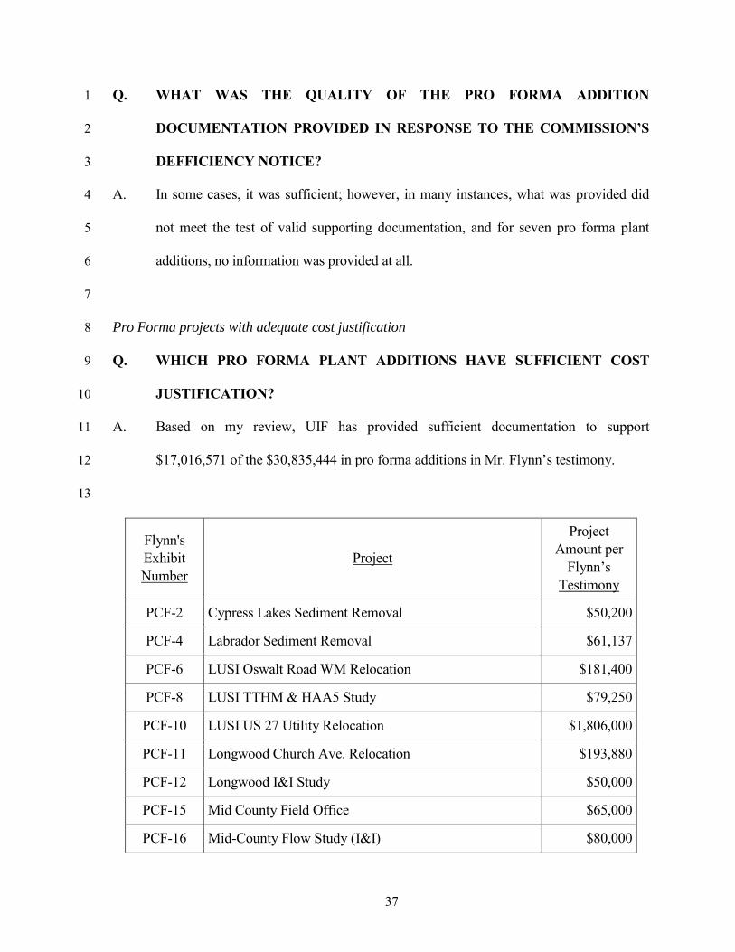
Q. WHICH PRO FORMA PLANT ADDITIONS HAVE SUFFICIENT COST 9
JUSTIFICATION? 10
A. Based on my review, UIF has provided sufficient documentation to support 11
$17,016,571 of the $30,835,444 in pro forma additions in Mr. Flynn’s testimony. 12
13
Flynn's Exhibit Number
Project
Project Amount per
Flynn’s Testimony
PCF-2 Cypress Lakes Sediment Removal $50,200
PCF-4 Labrador Sediment Removal $61,137
PCF-6 LUSI Oswalt Road WM Relocation $181,400
PCF-8 LUSI TTHM & HAA5 Study $79,250
PCF-10 LUSI US 27 Utility Relocation $1,806,000
PCF-11 Longwood Church Ave. Relocation $193,880
PCF-12 Longwood I&I Study $50,000
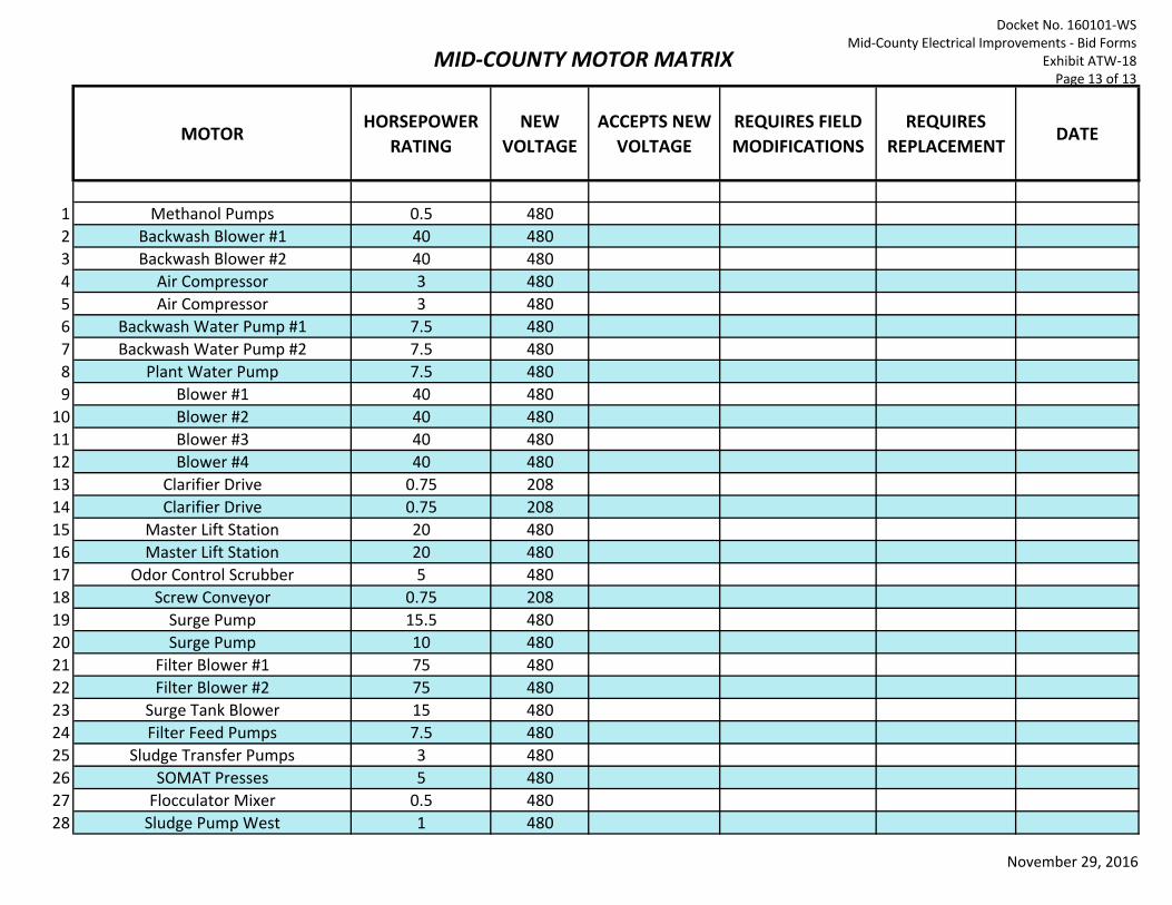
PCF-15 Mid County Field Office $65,000
PCF-16 Mid-County Flow Study (I&I) $80,000
38
PCF-22 Sanlando Autumn Wood Dr. WM Replacement $98,970
PCF-23 Sanlando Lift Station RTU Installation $353,200
Mr. Woodcock has been involved with many different facets of environmental engineering for 25 years. He has special expertise in utility master planning, due diligence investigations, utility valuations, financial feasibility analyses and business plans. Mr. Woodcock’s skills include assisting utilities prepare operating and capital programs and supporting those programs with a series of rates and charges to provide for their successful implementation. He is also experienced in conducting economic and feasibility analyses and serves as an expert witness on utility rate regulatory matters.
Utility Planning
Mr. Woodcock’s water and wastewater utility planning experience includes several master plans, and capital improvements programs that include water, wastewater and reclaimed water utilities. Recent planning projects include the City of Clermont Water, Wastewater and Reclaimed Water Master Plans, the City of Bartow Water Master Plan, and the City of Naples Integrated Water Supply Study. As part of the planning process, Mr. Woodcock has conducted numerous economic, present value and feasibility analyses that evaluate the financial impacts of utility programs and provide useful decision criteria for capital planning.
Mr. Woodcock has participated in over 60 water and wastewater utility valuations and acquisitions for utility systems located throughout the Southeast United States. The acquisition projects cover a wide range of utility system configurations and sizes and include engineering due diligence inspections, valuations, and financing activities associated with the transactions.
Additionally, Mr. Woodcock has experience in the review and analysis of water and wastewater utility rates, charges and impact fees. His experience also extends to providing financial feasibility documentation in support of revenue bonds and utility financial feasibility studies in support of capital funding.
International
Mr. Woodcock has been an integral team member on several infrastructure improvement programs for the US Agency for International Development (USAID). He has conducted field visits to Nigeria and Zambia to evaluate existing infrastructure; meet with prospective teaming partners to identify and recruit local designers; and interview local agency officials and stakeholders to identify project challenges, build consensus, formulate technical approaches, and secure buy-in for development programs.
Prior to his work on international development projects, Mr. Woodcock concentrated on water and wastewater utility planning in the United States. His experience includes master planning and capital improvements programs that include water, wastewater and reclaimed water utilities for major cities. As part of the planning process, Mr. Woodcock has conducted numerous economic, present value and feasibility analyses that evaluate the financial impacts of utility programs and provide useful decision criteria for capital planning. Additionally, Mr. Woodcock has experience in the review and analysis of water and wastewater utility rates, charges, and impact fees. His experience also extends to providing financial feasibility documentation in support of revenue bonds and utility financial feasibility studies in support of capital funding.
Education: MBA, Rollins College, 2001
MS, Environmental Engineering, University of Central Florida, 1989
BS, Environmental Engineering, University of Central Florida, 1988
Registrations/Certifications: Professional Engineer, Florida, No. 47118
Professional Affiliations: Water Environment Federation
American Water Works Association
Office Location: Orlando, FL
Total Years of Experience:
25
Years with Tetra Tech:
23
Docket No. 160101‐WSResume of Andrew T. Woodcock
Exhibit ATW‐1Page 1 of 6
Andrew T. Woodcock, PE Senior Project Manager
Woodcock, Page 2
EXPERIENCE
Utility Planning
20-Year Reuse Water Master Plan, Daytona Beach, FL. Project Manager. The Daytona Beach 20-Year Reuse Water Master Plan evaluated the existing city reuse system and provided a listing of projects to expand the City’s use of reclaimed water over the projection period. A hydraulic model of the system was created in Innovzye software using the City’s existing CAD drawings and as-builts of recent projects. A unique feature of the modeling effort was to effectively simulate a low pressure reclaimed water transmission line that also acts as an outfall to the Halifax River. When the WWTP produces water that does not meet public reuse standards the pipeline is the sole form of effluent disposal. The model was used to develop an operational protocol for the pipeline given these two conflicting uses. Once the CIP was determined a full reclaimed water rate study was performed to demonstrate how varying levels of investment in the CIP would affect reclaimed rates.
Water, Wastewater, and Reclaimed Water Rate Study, Naples, FL. 2007. Project Manager. Performed a study for the evaluation and adjustment of the City’s rate structures for water, wastewater and reclaimed water as necessary to recover costs from capital improvement projects and to promote water conservation. The rate study recommended the development of a tiered structure to promote water conservation and also provided for lower reclaimed water rates to promote the connection to the City’s non-mandatory reclaimed water system. The project included multiple public workshops for citizen input and presentations to the City Council, with ultimate adoption of the rate structure.
Water and Wastewater Utility Master Plan, Marion County, FL. Project Manager. In the previous four years prior to initiation of the Water and Wastewater Master Plan Marion County had quadrupled its utility customer base through a series of utility acquisitions is key growth areas. The primary focus of the Water and Wastewater Master Plan was to provide a roadmap to efficiently consolidate utility systems and establish four County sub regions that would serve as the future basis for utility planning and operations. The Master Plan presented a program for systematically decommissioning small package plants and expanding sub regional facilities to accommodate the existing customer base and projected growth.
Water System Master Planning, Mapping and Modeling, City of Bartow, FL. Project Manager. Tetra Tech was contracted by the City in 1996 to perform a water master plan. In 2008 Tetra Tech updated the master plan with new projections, an expanded hydraulic model and a revised CIP. The hydraulic model was revised to include completed system improvements and projected extensions to serve growth areas. The resulting CIP was classified by three project types; pressure improvements, fire flow improvements, and growth improvements. The master plan also included an upper level financial analysis that evaluated the impact of CIP funding on the cash flows of the system.
Integrated Water Resources Plan, City of Naples, FL. Financial Evaluation. Tetra Tech developed an integrated water resources plan for the City of Naples that evaluated all water supply options for a twenty year planning period. All available water supply source were considered including brackish ground water, stormwater, and surface water from the Golden Gate Canal and Naples Bay. Mr. Woodcock performed a financial evaluation of the most technically feasible alternatives to determine the short term impact of capital and operations costs on the utility’s cash flows.
Water and Wastewater Master Plan, City of Deltona, FL. Project Engineer. The water and wastewater master plans for the City of Deltona were the first master plans prepared on the systems since the City’s acquisition in 2003. In addition the projections and capacity analysis of facilities a hydraulic model was prepared for both the water and wastewater systems to document system behavior and act as a planning tool to develop the proposed CIP. Hydraulic deficiencies in the water and wastewater systems were already well documented by City staff. The models however, were very useful in determining the magnitude of the deficiencies and the appropriate course of corrective action. The wastewater model was used to determine
Docket No. 160101‐WSResume of Andrew T. Woodcock
Exhibit ATW‐1Page 2 of 6
Andrew T. Woodcock, PE Senior Project Manager
Woodcock, Page 3
force main routing to a new WWTP in the developing area of the City. The water model was field calibrated through pressure data record by the City and at remote locations as well as hydrant testing.
Water, Wastewater and Reclaimed Water Master Plan, City of Clermont, FL. 2014. Project Manager for three Master Plans for the City. The master plans were driven by near term permit limitations and accelerated growth in the City’s service area. A key component of the joint master planning effort was developing new hydraulic models for all three systems using WaterGEMSTM. Critical to the modeling effort was to simulate system changes as potable water irrigation customers are systematically converted to reclaimed service. As a result of the modeling pressure problems in the potable were alleviated once the conversions were complete allowing the City to reduce its near term CIP without compromising customer levels of service.
Water and Wastewater Connection Charge and Development Fee Study, City of Bartow, FL. Project Manager: Performed a development fee study to evaluate the impacts of projects on the City’s capital recovery charges. The study also included an analysis of the City’s connection fees for water meters and water and wastewater services. The development fee portion of the study utilized the replacement cost of the applicable portions of the water and wastewater system to establish the current system cost of capacity. The treatment and transmission components of both the water and wastewater system were evaluated separately to provide a functional component breakdown. The City’s industrial wastewater development surcharge was also reviewed. The study also evaluated the capacity definitions of an equivalent residential connection (ERC). Finally, the study updated the meter installation and water and wastewater connection fees to account inflationary changes.
Orange Tree Utilities Utility Valuation, Collier County, FL. Project Manager. Providing assistance to Collier County for the evaluation of the Orange County water and wastewater utility system to determine its condition and needs for improvement prior to acquisition by Collier County.
Series 2014 Water and Sewer Refunding Revenue Bonds, Pasco County, FL. 2014. Project Manager. Served as the Financial Feasibility Consultant for a $105 million revenue bond issue to fund capital improvement projects. Based on the financial strength of the utility and the projections performed by Tetra Tech the bonds have received a rating of AA from Fitch and AA+ from Standard and Poors.
Series 2008 Water and Sewer Refunding Revenue Bonds, Pasco County, FL. 2008. Project Manager. Served as the Financial Feasibility Consultant for a $182.5 million revenue bond issue to fund capital improvement projects. Based on the financial strength of the utility and the projections contained in Tetra Tech’s report the bonds have received an uninsured rating of AA- from Fitch.
West Virginia Planning and Development Council Regions 4 and 7
Source Water Protection Plans - Alternative Source Water Feasibility Analysis for over 20 water systems, 2015.
Deltona, FL
Consulting Engineers Report, Series 2003; Utility System Revenue Bonds, $81.72 million.
Water and Wastewater Impact Fee Study (2005)
Water and Wastewater Rate Study (2006)
Stormwater Utility Rate Study (2008, 2015)
Water and Wastewater Master Plans (2007)
Marion County, FL
Water and Wastewater Impact Fee Study (2005)
Water and Wastewater Utility Master Plan (2005)
Docket No. 160101‐WSResume of Andrew T. Woodcock
Exhibit ATW‐1Page 3 of 6
Andrew T. Woodcock, PE Senior Project Manager
Woodcock, Page 4
City of Orlando, FL
Research Park Reuse Economic Impact Evaluation (2005)
Collier County, FL
Impact Fee Calculation Review (2011)
Meter Accuracy Program and Assessment (2012)
Meter Sizing Policy Review (2012)
Fire Assembly Inventory and Review (2013)
Utility Conveyance Policy Review (2014)
Orange Tree Utilities Due Diligence Investigation (2013)
Acquisition of Little Rock AFB Water System (2015)
City of Clermont, FL
Water, Wastewater and Reclaimed Water Master Plans (2014)
International
USAID, Sustainable Water and Sanitation for Africa, Zambia. 2012 - 2013. Senior Technical Lead for a Cost of Service Study of the 11 utilities that serve domestic, intuitional and commercial customers to ensure that the utilities can operate as commercially viable utilities, and reliably meet the water and sanitation demand within the service areas. The project supports Zambia’s National Water Supply and Sanitation Council (NWASCO) with the overall goal to improve sustainability through promotion of cost recovery throughout Zambia’s urban water sector. Conducted initial interviews with NWASCO management and other stakeholders including USAID, MCC, and the eleven commercial utilities. Developed a comprehensive cost of service model to benchmark utility costs against known values and project future costs of service based on numerous escalation factors. The model was presented to NWASCO and representatives of the utilities in two workshops that included not only an overview of the model purpose but also specific training in the use of the model.
USAID, Sustainable Water and Sanitation for Africa, Nigeria. 2012 – 2014. Water Supply Investment Expert for development of an investment plan for urban water supply and sanitation sector of Bauchi State. The plan provides advice for improving budgeting, financial planning, and attracting external funding sources. Prepared a Water Supply Investment Plan, Long Term Business Plan, and Medium Term Business Plan for the local water service provider, Bauchi State Water Board (BSWB). The overall goal of this project is to improve the operating environment of the urban water service provider through promoting good governance, autonomy of the water service provider and promotion of sustainable financing for urban water supply and sanitation services. Conducted a field mission to Nigeria to meet with the BSWB leaders, study existing funding arrangements for capital and recurrent urban water supply expenditure, and assist in assess capital investment needs as well as operations and maintenance needs. The Water Supply Investment Plan and Business Plans will be used to attract investments from international bilateral donors.
USAID Liberia Municipal Water Project, Liberia. 2014. Team Leader for strategic and business planning development of five water supply outstations. The development consisted of two sets of workshops designed to educate and develop business plans for five water systems in Liberia. The workshops were attended by numerous utility stakeholders including system operations and management personnel, community leaders and representatives from the Liberia Water and Sanitation Corp. The first workshop introduced the concepts and components of a business plan. The audience was divided into several working groups that were guided through a number of exercises to develop the major components of a business plan. The second round of workshops introduced the business plan template and guided the working groups through the initial development of the business plan that was later finalized by the water systems.
USAID Sustainable Water and Sanitation for Africa, South Sudan. 2014. Technical Leader for the development of an Investment Plan for sanitation for the City of Juba. The goal of the investment plan is to provide a pathway for the technical, financial and institutional expansion of sanitation in a city of approximately 500,000 people. The plan expands coverage of sanitation in the city initially through the expansion of latrines, supported by a system of exhauster trucks and a treatment lagoon. In later stages the plan envisions the gradual implementation of a piped sewerage system. The plan also provides guidance on the development of an institutional framework, defining the roles of national, state and, local governing bodies. Finally the plan provides a financial plan with emphasis on the steps required to attract investment from the private and donor sectors.
Docket No. 160101‐WSResume of Andrew T. Woodcock
Exhibit ATW‐1Page 5 of 6
Andrew T. Woodcock, PE Senior Project Manager
Woodcock, Page 6
PAPERS/PRESENTATIONS
"Water and Wastewater Impact Fees: An Overview" Alabama Water Pollution Control Association, July 28, 2008.
“Developing Multi-Year Business Plans and Infrastructure Master Plans,” Institute for Public Private Partnerships (IP3), August 2015.
Docket No. 160101‐WSExcessive Inflow and Infiltration Calculations
Exhibit ATW‐3Page 1 of 1
System
Wastewater
Treatment
Wastewater
Collection
Crownwood 53.20% NA
Eagle Ridge 100.00% 100%
Labrador 40.59% NA
Lake Placid 29.79% NA
LUSI 53.55% NA
Mid County 93.67% 100.00%
Sandalhaven - EWD Cap 42.24% NA
Sandalhaven - Lift Station 11.27% NA
Sandalhaven - Force Main 13.55% NA
Sandalhaven - Pumps 27.25% NA
Docket No. 160101-WSSummary of Used and Useful Percentages
Exhibit ATW-4Page 1 of 1
Docket No. 160101-WSLUSI Used and Useful Calculations
Exhibit ATW-5Page 1 of 1
LUSI
Line Description1 Test Year Flows(1)
2 Annual Average (MGD) 0.452 34 Growth Adjustment5 Test Year ERCs(2) 34416 Annual Growth Using Linear Regression (ERCs/yr)(3) 1267 Growth for Five year Period (ERCs) 6318 Test Year gpd/ERC (Line 2 /Line 5) 131 9 Growth Allowance (MGD) (Line 8*Line 7) 0.083
1011 Test year Flow Plus Growth Allowance (Line 2+line 9) 0.535 1213 Inflow/Infiltration Adjustment14 Excess I&I (gpy) - 15 Excess I&I (gpd) - 1617 Test year Flow with Growth Allowance Less I&I (Line 11-Line 15) 0.535 1819 Capacity (MGD) 0.999 2021 Used and Useful Percentage 53.55%22 Non-Used and Useful Percentage 46.45%
Notes(1) From test year DMRs(2) From MFR Schedue F-10(3) From MFR Schedue F-10
Docket No. 160101-WSMid County Used and Useful Calculations
Exhibit ATW-6Page 1 of 1
Mid County
Line Description1 Test Year Flows(1)
2 Annual Average (MGD) 0.789 34 Growth Adjustment5 Test Year ERCs(2) 20016 Annual Growth Using Linear Regression (ERCs/yr)(3) 277 Growth for Five year Period (ERCs) 1368 Test Year gpd/ERC (Line 2 /Line 5) 395 9 Growth Allowance (MGD) (Line 8*Line 7) 0.054
1011 Test year Flow Plus Growth Allowance (Line 2+line 9) 0.843 1213 Inflow/Infiltration Adjustment14 Excess I&I (gpy) - 15 Excess I&I (gpd) - 1617 Test year Flow with Growth Allowance Less I&I (Line 11-Line 15) 0.843 1819 Capacity (gpd) 0.900 2021 Used and Useful Percentage 93.67%22 Non-Used and Useful Percentage 6.33%
Notes(1) From test year DMRs(2) From MFR Schedue F-10(3) From MFR Schedue F-10
Docket No. 160101‐WSLake Placid Used and Useful Calculations
Exhibit ATW‐7Page 1 of 1
Lake Placid
Line Description
1 Test Year Flows(1)
2 Annual Average (MGD) 0.018
3
4 Growth Adjustment
5 Test Year ERCs(2) 349
6 Annual Growth Using Linear Regression (ERCs/yr)(3) 32
7 Growth for Five year Period (ERCs) 159
8 Test Year gpd/ERC (Line 2 /Line 5) 53
9 Growth Allowance (MGD) (Line 8*Line 7) 0.008
10
11 Test year Flow Plus Growth Allowance (Line 2+line 9) 0.027
12
13 Inflow/Infiltration Adjustment
14 Excess I&I (gpy) ‐
15 Excess I&I (gpd) ‐
16
17 Test year Flow with Growth Allowance Less I&I (Line 11‐Line 15) 0.027
18
19 Capacity (gpd) 0.090
20
21 Used and Useful Percentage 29.79%
22 Non‐Used and Useful Percentage 70.21%
Notes
(1) From test year DMRs
(2) From MFR Schedue F‐10
(3) From MFR Schedue F‐10
Docket No. 160101-WSLake Placid FDEP Construction Application
Exhibit ATW-8Page 1 of 13
Florida Department d Environmental Protection
NOTIFICATION/APPLICATION FOR CONSTRUCTING A DOMESTIC WASTEWATER COLLECTION/TRANSMISSION SYSTEM
PART I- GENERAL
Subpart A: Pennit Application Type
Permit Application Type (mark one only) ED Us Application Fee* Served
Are you applying for an individual permit for a domestic wastewater collection/transmission :::_ to $500 system? Note: an EDU is equal to 3.5 persons. Criteria for an individual pcnnit are contained in Rule 62-604.600(7}, F.A.C.
< 10 $300
Is this a Notice of Intent to use the general permit for wastewater collection/transmission systems? N/A $250 Criteria for qualifying for a general permit are contained in Rule 62-604.600(6), F.A.C. Projects not meeting the criteria in Rule 62-604.600(6}, F.A.C., must apply for an individual permit.
ux"
X
*Note: Each non-contiguous project (i .e., projects that are not interconnected or are not located on adjacent streets or in the same neighborhood) requires a separate application and fee.
Subpart B: Instructions
(I) This form shall be completed for all domestic wastewater collection/transmission system construction projects as follows: • If this is a Notice of Intent to use the general permit, this notification shall be submitted to the Department at least 30 days prior to
initiating construction. • If this is an application for an individual pcnnit, the permit must be obtained prior to initiating construction.
(2) One copy of the completed form shall be submitted to the appropriate DEP district office or delegated local program along with the appropriate fee, and one copy of the following supporting documents. Checks should be made payable to the Florida Department of Environmental Protection, or the name of the appropriate delegated local program.
• If this is a Notice of Intent to use the general penn it, attach a site plan or sketch showing the size and approximate location of new or altered gravity sewers, pump stations and force mains; showing the approximate location of manholes and isolation valves; and showing how the proposed project ties into the existing or proposed wastewater facilities. The site plan or sketch shall be signed and scaled by a professional engineer registered in Florida.
• If this is an application for an individual permit, one set of plans and specifications shall be submitted with this application, or alternatively, an engineering report shall be submitted. Plans and specifications and engineering reports shall be prepared in accordance with the applicable provisions of Chapters 10 and 20 of Recommended Standards for Wastewater Facilities. The plans and specifications or engineering report shall be signed and sealed by a Professional Engineer registered in Florida.
(3) All information shall be typed or printed in ink. Where attached sheets (or other technical documentation) are utilized in lieu of the blank spaces provided, indicate appropriate cross-references on the form. For Items (I) through (4) of Part II of this application fonn, if an item is not applicable to your project, indicate ''NA" in the appropriate space provided.
DEP Fonn 62·604 300(8)(a) EITecuve November 6. 2003
Page 1 of 11
Beltran_M
date
Docket No. 160101-WSLake Placid FDEP Construction Application
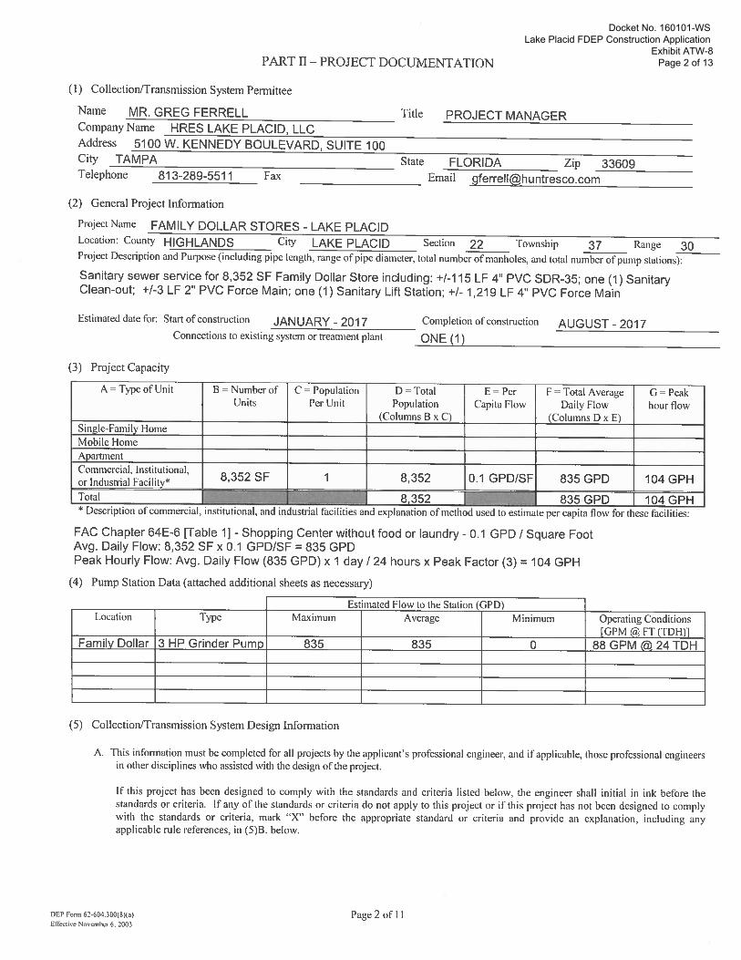
Exhibit ATW-8Page 2 of 13PART II- PROJECT DOCUMENTATION
(I) Collection!fransmission System Permittee
Name MR. GREG FERRELL Title PROJECT MANAGER Company Name HRES LAKE PLACID, LLC Address 5100 W. KENNEDY BOULEVARD, SUITE 100 City TAMPA State FLORIDA Zip 33609 ----------Telephone 813-289-5511 Fax ---------------- Email [email protected]
(2) General Project Information
Project Name FAMILY DOLLAR STORES -LAKE PLACID Location: County HIGHLANDS City LAKE PLACID Section 22 Township 37 Range
~~-- ----- 30 Project Description and Purpose (including pipe length, range of pipe diameter, total number of manholes, and total number of pump stations):
Sanitary sewer service for 8,352 SF Family Dollar Store including: +1-115 LF 4" PVC SDR-35; one (1) Sanitary Clean-out; +1-3 LF 2" PVC Force Main; one (1) Sanitary Lift Station; +1-1,219 LF 4" PVC Force Main
Estimated date for: Start of construction JANUARY- 2017 Completion of construction AUGUST - 2017 ----------------------Connections to existing system or treatment plant ONE ( 1 )
(3) Project Capacity
A = Type of Unit B = Number of C = Population D = Total E = Per F = Total Average G = Peak Units Per Unit Population Capita Flow Daily Flow hour flow
(Columns B x C) (Columns D x E) Single-Family Home Mobile Home Apartment Commercial, Institutional ,
8,352 SF 1 8,352 0.1 GPD/SF 835 GPD 104 GPH or Industrial Facility*
0 •• * Descnpt10n of commercml, mstttuttonal, and mdustnal factltttes and explanatton of method used to esttmate per captta flow for these factltttes:
FAC Chapter 64E-6 [Table 1]- Shopping Center without food or laundry- 0.1 GPD I Square Foot Avg. Daily Flow: 8,352 SF x 0.1 GPDISF = 835 GPD Peak Hourly Flow: Avg. Daily Flow (835 GPD) x 1 day I 24 hours x Peak Factor (3) = 104 GPH
(4) Pump Station Data (attached additional sheets as necessary)
Estimated Flow to the Station (GPD) Location Type Maximum Average Minimum
Family Dollar 3 HP Grinder Pumo 835 835 0
(5) Collection!fransmission System Design Information
Operating Conditions [GPM @ FT (TDH)l
88 GPM @ 24 TDH
A. This information must be completed for all projects by the applicant's professional engineer, and if applicable, those professional engineers in other disciplines who assisted with the design of the project.
If this project has been designed to comply with the standards and criteria listed below, the engineer shall initial in ink before the standards or criteria. If any of the standards or criteria do not apply to this project or if this project has not been designed to comply with the standards or criteria, mark " X" before the appropriate standard or criteria and provide an explanation, including any applicable rule references, in (5)8 . below.
DEP Fonn 62·604.300(8)(a) Effective NovembeT 6. :!003
Page 2 of II
Docket No. 160101-WSLake Placid FDEP Construction Application
Exhibit ATW-8Page 3 of 13
~_£ 2.
~3.
Zk 4.
n-5. n_ 6.
13 7.
n- 8.
~9.
Note, if the project has rlllt been designed in accordance \\ilh the standards and criteria sc:t forth in Rules 62-604.400( 1) nnd (1), F.A.C., nn application for an indh idunl permit shall he submitted. Howc,·er. if Rules 62-604.400( I) nnd (2). F.A.C., specifically allow for :mother altemali\'e that will rcsull in nn equivalent level of reliability and public health protection. the project can be constructed using the general permit.
General Requirements
The project is designed based on an average daily flow of 100 gallons per capita plus wastewater flow from industrial plants and major institutional and commercial facilities unless water use data or other justification is used to better estimate the flow. The design includes an appropriate peaking factor, which covers Ill contributions and non-wastewater connections to those service lines. [RSWF 11.2431
Procedures are specified for operation of the collection/transmission system during construction. [RSWF 20.15j
The project is designed to be located on public right-of-ways, land owned by the pem1ittee, or easements and to be located no closer than I 00 feet from a public drinking water supply well and no closer than 75 feet from a private drinking water supply well; or documentation is provided in Part 11.(5)8., showing that another alternative will result in an equivalent level of reliability and public health protection. (62-604.400( I )(b) and (c), F.A.C.]
The project is designed with no physical connections between a public or private potable water supply system and a sewer or force main and with no water pipes passing through or coming into contact with any part of a sewer manhole. (RSFW 38.1 and 48.5]
The project is designed to preclude the deliberate introduction of storm water, surface water, groundwater, roof runoff, subsurface drainage, swimming pool drainage, air conditioning system condensate water, non-contact cooling water except as provided by Rule 62·61 0.668( I), F.A.C., and sources of uncontaminated wastewater, except to augment the supply of reclaimed water in accordance with Rule 62-610.472(3 )(c), F.A.C . [62-604.400( I )(d), F.A.C.]
The project is designed so that all new or relocated, buried sewers and force mains, arc located in accordance with the separation requirements from water mains and reclaimed water lines of Rules 62-604.400(2)(g)(h) and (i) and (3), F .A.C. Note, if the criteria of Rules 62-604.400(2)(g) 4. or (2)(i) 3., F.A.C., are used, describe in Part ll.(S)BG. alternative
construction features that will be provided to afford a similar level of reliability and public health protection. [62-604.400(2)(g), (h), and (i) and (3), F.A.C.]
Gravity Sewers
The project is designed with no public gravity sewer conveying raw wastewater less than 8 inches in diameter. [RSWF 33.1]
The design considers buoyancy of sewers, and appropriate construction techniques are specified to prevent flotation of the pipe where high groundwater conditions are anticipated. [RSWF 33.3}
All sewers arc designed with slopes to give mean velocities, when flowing full, of not less than 2.0 feet per second, based on Manning's formula using an "n" value of 0.0 13; or if it is not practicable to maintain these minimum slopes and the depth of flow will be 0.3 of the diameter or greater for design average flow, the owner of the system has been notified that additional sewer maintenance will be required. The pipe diameter and slope are selected to obtain the greatest practical velocities to minimize solids deposition problems. Oversized sewers are not specified to justify flatter slopes. [RSWF 33.41, 33.42, and 33.43]
te 10. Sewers arc designed with uniform slope between manholes. [RWSF 33.44]
X
X
II. Where velocities greater than I 5 fps are designed, provisions to protect against displacement by erosion and impact arc specified. [RSWF 33.45]
12. Sewers on 20% slopes or greater are designed to be anchored securely with concrete, or equal, anchors spaced as follows: not over 36 feet center to center on grades 20% and up to 35%; not over 24 feet center to center on grades 35% and up to 50%; and not over 16 feel center to center on grades 50% and over. [RSWF 33.46]
DEP Furm 6l.oo.ll00(1Kal ER'~tuve No~cn*• 6 2001
Page 3oft I
Docket No. 160101-WSLake Placid FDEP Construction Application
Exhibit ATW-8Page 4 of 13
2_Pt7.
ylll.
Sewers 24. mches or less are designed with straight alignment between manholes. Where curvilinear sewers are proposed for sewers greater than 24 inches, the design specifies compression joints; ASTM or speci fie pipe manufacturer's maximum allowable pipe joint deflection limits are not exceeded; and curvilinear sewers are limited to simple curves which start and end at manholes. [RSWF 33.5]
Suitable couplings complying with ASTM specifications are required for joining dissimilar materials. [RSWF 33.7]
Sewers are designed to prevent damage from superimposed loads. [RSWF 33.7]
Appropriate specifications for the pipe and methods of bedding and backfilling are provided so as not to damage the pipe or its joints, impede cleaning operations and future tapping, nor create excessive side fill pressures and ovalation of the pipe, nor seriously impair flow capacity. [RSWF 33.81]
Appropriate deflection tests are specified for all flexible pipe. Testing is required after the final backfill has been in place at least 30 days to permit stabili7.ation of the soil-pipe system. Testing requirements specifY: I) no pipe shall exceed a deflection of 5%; 2} using a rigid ball or mandrel for the deflection test with a diameter not less than 95% of the base inside diameter or average inside diameter of the pipe, depending on which is specified in Lhe ASTM specification, including the appendix, to which the pipe is manufactured; and 3) performing the test without mechanical pulling devices. [RSWF 33.85]
Leakage tests are specified requiring that: I) the leakage exfiltration or infiltration does not exceed 200 gallons per inch of pipe diameter per mile per day for any section of the system; 2) exfiltration or infiltration tests be performed with a minimum positive head of2 feet; and 3) air tests, as a minimum, conform to the test procedure described in ASTM C-818 for clay pipe, ASTM C 924 for concrete pipe, ASTM F-14 I 7 for plastic pipe, and for other materials appropriate test procedures. [RSWF.l3.9l, 33.94, and 33.95]
X 19. If an inverted siphon is proposed, documentation of its need is provided in Pan ll.i1)J1G. Inverted siphons arc designed with: I) at least two barrels; 2) a minimum pipe size of 6 inches; 3) necessary a1>purtenances for maintenance, convenient flushing, and cleaning equipment; and 4) inlet and discharge structures having adequate clearances for cleaning equipment, inspection, and flushing. Design provides sufficient head and appropriate pipe sizes to secure velocities of nt least 3.0 fps for design average flows. The inlet and outlet nrc designed so that the design average tlow may be diverted to one barrel, and that either barrel may be cut out of service for cleaning. [RSWF 35)
Manholes
X 20. The project is designed with manholes at the end of each line; at all changes in grade, size, or alignment; at all intersections; and at distances not greater than 400 feet for sewers 15 inches or less and 500 feet for sewers 18 inches to 30 inches, except in the case where adequate modem cleaning equipment is available at distances not greater than 600 feet. [RSWF 34.1)
X 21. Design requires drop pipes to be provided for sewers entering manholes at elevations of 24 inches or more above the manhole invert. Where the difference in elevation between the incoming sewer and the manhole invert is less than 24 inches, the invert is designed with a fillet to prevent solids deposition. Inside drop connections (when necessary) arc designed to be secured to the interior wall of the manhole and provide access for cleaning. Design requires the entire outside drop connection be encased in concrete. [RSWF 34.2]
X 22. Manholes are designed with a minimum diameter of 48 inches and a minimum access diameter of 22 inches. [RSWF 34.3]
X 23. Design requires that a bench be provided on each side of any manhole channel when the pipe diameter(s) are less than the manhole diameter and that no lateral sewer, service connection, or drop manhole pipe discharges onto the surface of the bench. [RSWF 34.5]
X 24. Design requires: I) manhole lift holes and grade adjustment rings be sealed with non-shrinking mortar or other appropriate material: 2) inlet and outlet pipes be joined to the manhole with a gasketed flexible watertight connection or another watertight connection arrangement that allows differential settlement of the pipe and manhole wall; and 3) watenight manhole covers be used wherever the manhole lops may be flooded by street runofTor high water. [RSWF 34.6]
X 25. Manhole inspection and testing for watertightness or damage prior to placing into service arc specified Air testing, if specified for concrete sewer manholes, conforms to the test procedures described in ASTM C-1244 [RSWF 34. 7]
X 26. Electrical equipment specified for use in manholes is consistent with Item 46 of this checklist. [RSWF 34.9)
DEr FarmGl-60J lOO(IM•I Elfccu•• NO\·cmbo:r 6, 1001
Pagc4 of II
Docket No. 160101-WSLake Placid FDEP Construction Application
Exhibit ATW-8Page 5 of 13
X
X
X
X
X
Stream Crossings
27. Sewers and force mains entering or crossing streams are designed to be constructed of ductile iron pipe with mechanical joints or so they will remain watertight and free from changes in alignment or grade. Appropriate materials which will not readily erode, cause siltation, damage pipe during placement, or corrode the pipe are specified to backfill the trench. [RSWF 36.21 and 48.5]
28. Stream crossings are designed to incorporate valves or other flow regulating devices (which may include pump stations) on the shoreline or at such distances .fuwl.feml the shoreline to prevent discharge in the event the line is damaged. [62-604.400(2)(1\)5., F.A.C.]
29. Sewers and force mains entering or crossing streams are designed at a sufficient depth below the natural bottom of the stream bed to protect the line. At a minimum, the project is designed with subaqueous lines to be buried at least three feet below the design or actual bottom, whichever is deeper, of a canal and other dredged waterway or the natural bottom of streams, rivers, estuaries, bays, and other natural water bodies; or if it is not practicable to design the project with less than three-foot minimum cover, alternative construction features (e.g. a concrete cap, sleeve, or some other properly engineered device to insure adequate protection of the line) arc described in Part II. C. [62-604.400(2)(k) 1., F.A.C., and RSWF 36.11)
30. Specifications require permanent warning signs be placed on the banks of canals, streams, and rivers clearly identifying the nature and location (including depths below design or natural bottom) of subaqueous crossings and suitably fixed signs be placed at the shore, for subaqueous crossings of lakes, bays, and other large bodies of water, and in any area where anchoring is normally expected. [62-604.400(2)(k)2., F.A.C.]
31. Provisions for testing the integrity of subaqueous lines are specified. [62-604 .400(2)(k)4 , F. A C.]
X 32. Supports are designed for all joints in pipes utilized for aerial crossings and to prevent overturning and settlemenl.
X
Expansion jointing is specified between above ground and below ground sewers and force mains. The design considers the impact of floodwaters and debris. [RSWF 37 and 48.5]
33. Aerial crossings are designed to maintain existing or required navigational capabilities within the watenvay and to reserve riparian rights of adjacent property owners. [62-604.400(2)(k)J., F.A.C.)
Pump Stations
;J} 34. In areas with high water tables, pump stations are designed to withstand flotation forces when empty. When siting the pump station, the design considers the potential for damage or interruption of operation because of flooding. Pump station structures and electrical and mechanical equipment are designed to be protected from physical damage by the I 00-yenr flood. Pump stations are designed to remain fully operational and accessible during the 25-year flood unless lesser flood levels are appropriate based on local considerations, but not less than the I 0-year flood. [62-604.400(2)(e), F.A.C.]
~5. Pump stations are designed to be readily accessible by maintenance vehicles during all weather conditions. [RSWF 41.2]
~ 36. Wet well and pump station piping is designed to avoid operational problems from the accumulation of grit. [RSWF 41.31
X 37. Dry wells, including their superstructure, are designed to be completely separated from the wet well. Common walls nrc designed to be gas tight. [RSWF 42.21]
X 38. The design includes provisions to facilitate removing pumps, motors, and other mechanical and electrical equipmenl. [RSWF 42.22}
DEr l'orm 62-60ol lOOIIM•l Eft'ea•'-r No,·rmbct 6. 2001
Page 5 of II
Docket No. 160101-WSLake Placid FDEP Construction Application
Exhibit ATW-8Page 6 of 13
X 39.
:JP4o. ~41 .
The design includes provisions for: I) suitable and safe means of access for persons wearing self-contained breathing apparatus are provided to dry wells, and to wet wells; 2) stairway access to wet wells more than 4 feet deep containing either bar screens or mechanical equipment requiring inspection or maintenance; 3) for built-in-place pump stations, a stairway to the dry well with rest landings at vertical intervals not to exceed 12 feet; 4) for factory-built pump stations over 15 feet deep, a rigidly fixed landing at vertical intervals not to exceed 10 feet unless a man lift or elevator is provided; and 5) where a landing is used, a suitable and rigidly fixed barrier to prevent an individual from falling past the intennediate landing to a lower level. If n manlift or elevator is provided, emergency access is included in the design. [RSWF 42.23)
Specified construction materials arc appropriate under conditions of exposure to hydrogen sulfide and other corrosive gases, greases, oils, and other constituents frequently present in wastewater. [RSWF 42.25]
Except for low-pressure grinder or STEP systems, multiple pumps are specified, and each pump has an individual intake. Where only two units are specified, they are of the same size. Specified units have capacity such that, with any unit out
of service, the remaining units will have capacity to handle the design peak hourly flow. [RSWF 42.31 and 42.36} X 42. Bar racks arc specified for pumps handling wastewater from 30 inch or larger diameter sewers. Where a bar rack is
specified, a mechanical hoist is also provided. The design includes provisions for appropriate protection from clogging for small pump stations. [RSWF 42.322)
X 43. Pumps handling raw wastewater are designed to pass spheres of at least 3 inches in diameter. Pump suction and discharge openings are designed to be atleast4 inches in diameter. [RSWF 42.33] (Note, this provision is not applicable to grinder pumps.)
7l} 44.
J!P4s. The design requires pumps be placed such that under normal operating conditions they will operate under a positive suction head, unless pumps are suction-lift pumps. [RSWF 42.34]
The design requires: I) pump stations be protected from lightning and transient voltage surges; and 2) pump stations be equipped with lighting arrestors, surge capacitors, or other similar protection devices and phase protection. Note, pump stations serving a single building are not required to provide surge protection devices if not necessary to protect the pump station. [62-604.400(2)(b), F.A.C.]
The design requires I) electrical systems and components (e.g., motors, lights, cables, conduits, switch boxes, control circuits, etc.) in raw wastewater wet wells, or in enclosed or partially enclosed spaces where ha7.ardous concentrations of flammable gases or vapors may be present, comply with the National Electrical Code requirements for Class I Group D, Division I locations; 2) electrical equipment located in wet wells be suitable for use under corrosive conditions; 3) each nexible cable be provided with a watertight seal and separate strain relief; 4) a fused disconnect switch located above ground be provided for the main power feed for all pump stations; 5) electrical equipment exposed to weather to meet the requirements of weatherproof equipment NEMA 3R or 4; 6) a II 0 volt power receptacle to facilitate maintenance be provided inside the control panel for pump stations that have control panels outdoors; and 7) ground fault interruption protection be provided for all outdoor outlets. [RSWF 42.35]
X 47. The design requires a sump pump equipped with dual check valves be provided in dry wells to remove leakage or drainage with discharge above the maximum high water level of the wet well. [RSWF 42.37]
1[}48.
_:n 49.
_il35o.
j[B 51.
~52.
Pump station design capacities arc based on the peak hourly flow and are adequate to maintain a minimum velocity of2 feet per second in the force main. [RSWF 42.38]
The design includes provisions to automatically alternate the pumps in use. [RSWF 42.4]
The design requires: I) suitable shutoff valves be placed on the suction line or dry pit pumps; 2) suitable shutoff and check valves be placed on the discharge line of each pump (except on screw pumps); 3) a check valve be located between the shutoff valve and the pump; 4) check valves be suitable for the material being handled; 5) check valves be placed on the horizontal portion of discharge piping (except for ball checks, which may be plnced in the vertical run); 6) all valves be capable of withstanding normal pressure and water hammer; and 7) all shutoff and check valves be operable from the floor level and accessible for maintenance. [RSWF 42.5]
The effective volume of wet wells is based on design average flows and a filling time not to exceed 30 minutes unless the facility is designed to provide flow equalization The pump manufacturer's duty cycle recommendations were utilized in selecting the minimum cycle time [RSWF 42.62]
The design requires wet well noors have a minimum slope of I to I to the hopper bottom and the horizontal area of hopper bottoms be no greater than necessary for proper ~nstallation and function of the inlet. [RSWF 42.63]
DEr Form 62·6GI lOO(IKol Elf«ll•c No--cmll<r 6 lOOJ
l'agc 6 of II
Docket No. 160101-WSLake Placid FDEP Construction Application
Exhibit ATW-8Page 7 of 13
X
X
X
X
X
53. For covered wet wells, the design provides for air displacement to the atmosphere, such as an inverted "j" tube or other means. [RSWF 42.64]
54. The design provides for adequate ventilation all pump stations; mechanical ventilation where the dry well is below the ground surface; permanently installed ventilation if screens or mechanical equipment requiring maintenance or inspection are located in the wet well. Pump stations are designed with no interconnection between the wet well and dry well ventilation systems. [RSWF 42.71]
55. The design requires all intermittently operated ventilation equipment to be interconnected with the respective pit lighting system and the manual lighting/ventilation switch to override the automatic controls. [RSWF 42. 73]
56. The design requires the fan wheels of ventilation systems be fabricated from non-sparking material and automatic heating and dehumidification equipment be provided in all dry wells. [RSWF 42.74]
57. If wet well ventilation is continuous, design provides for at least 12 complete 100% fresh air changes per hour; if wet well ventilation is intermittent, design provides for at least 30 complete I 00% fresh air changes per hour; and design requires air to be forced into wet wells by mechanical means rather than solely exhausted from the wet well. [RSWF 42.75)
58. If dry well ventilation is continuous, design provides at least 6 complete 100% fresh air changes per hour; and dry well ventilation is intermittent, design provides for at least 30 complete 100% fresh air changes per hour, unless a system of two speed ventilation with an initial ventilation rate of 30 changes per hour for I 0 minutes and automatic switch over to 6 changes per hour is used to conserve heat. [RSWF 42.76)
~59.
1!} 60.
Pump stations are designed and located on the site to minimize adverse effects from odors, noise, and lighting. [62-604.400(2)(c), F.A.C.)
The design requires pump stations be enclosed with a fence or otherwise designed with appropriate features to discourage the entry of animals and unauthorized persons. Posting of an unobstructed sign made of durable weather resistant material at a location visible to the public with a telephone number for a point of contact in case of emergency is specified. [62-604.400(2)(d), F.A.C.]
X
X
61. The design requires suitable devices for measuring wastewater flow at all pump stations. Indicating, totalizing, and recording flow measurement are specified for pump stations with a 1200 gpm or greater design peak flow. [RS WF 42.8]
62. The project is designed with no physical connections between any potable water supplies and pump stations. If a potable water supply is brought to a station, reduced-pressure principle backflow-prevention assemblies are specified. [RSWF 42.9 and 62-555.30(4), F.A.C.]
Additional Items to be Completed for Suction-Lift Pump Statjons
63. The design requires all suction-lift pumps to be either self-priming or vacuum-priming and the combined total of dynamic suction-lift at the "pump ofr' elevation and required net positive suction head at design operating conditions not to exceed 22 feet For self-priming pumps, the design requires: I) pumps be capable of rapid priming and repriming at the "lead pump on" elevation with self-priming and repriming accomplished automatically under design operating conditions; 2) suction piping not to exceed the size of the pump suction or 25 feet in total length; and 3) priming lift at the "lead pump on" elevation to include a safety factor of at least 4 feel from the maximum allowable priming lift for the specific equipment at design operating conditions. For vacuum-priming pump stations, the design requires dual vacuum pumps capable of automatically and completely removing air from the suction-lift pumps and the vacuum pumps be adequately protected from damage due to wastewater. [RSWF 43.1]
64. The design requires: I) suction-lift pump equipment compartments to be above grade or offset and to be effectively isolated from the wet well to prevent a hazardous and corrosive sewer atmosphere from entering the equipment compartment; 2) wet well access not to be through the equipment compartment and to be at least 24 inches in diameter; 3) gaskcted replacement plates be provided to cover the opening to the wet well for pump units to be remove for service; and 4) no valving be located in the wet well. [RSWF 43.2]
Docket No. 160101-WSLake Placid FDEP Construction Application
Exhibit ATW-8Page 8 of 13
n65. Additional Items to be Completed for Submersible Pump Stations
Submersible pumps and motors are designed specifically for raw wastewater use, including totally submerged operation during a portion of each pump cycle and to meet the requirements of the National Electrical Code for such units. Provisions for detecting shaft seal failure or potential seal failure arc included in the design. [RSWF 44.1] .D 66. The design requires submersible pumps be readily removable and replaceable without dewatering the wet well or disconnecting any piping in the wet well. [RSWF 44.2)
67. In submersible pump stations, electrical supply, control, and alarm circuits are designed to provide strain relief; to allow disconnection from outside the wet well; and to protect terminals and connectors from corrosion by location outside the wet well or through use of watertight seals. [RSWF 44.31]
~ 68.
71-69.
11- 70.
'}Z71.
~72.
/}1 73 .
In submersible pump stations, the design requires the motor control center to be located outside the wet well, readily accessible, and protected by a conduit seal or other appropriate measures meeting the requirements of the National Electrical Code, to prevent the atmosphere of the wet well from gaining access to the control center. If a seal is specified, the motor can be removed and electrically disconnected without disturbing the seal. The design requires control equipment exposed to weather to meet the requirements of weatherproof equipment NEMA 3R or 4. [RSWF 44.32]
In submersible pump stations, the design requires: I) pump motor power cords be Ocxiblc and serviceable under conditions of extra hard usage and to meet the requirements of the National Electrical Code standards for flexible cords in wastewater pump stations; 2) ground fault interruption protection be used to de-energize the circuit in the event of any failure in the electrical integrity of the cable; and 3) power cord tenninal fittings be corrosion-resistant and constructed in a manner to prevent the entry of moisture into the cable, provided with strain relief appurtenances, and designed to facilitate field connecting. [RSWF 44.33]
In submersible pump stations, the design requires all shut-off and check valves be located in a separate valve pit. Provisions to remove or drain accumulated water from the valve pit are included in the design. [RSWF 44.4]
Emergency Operations for Pump Stations
Pump stations are designed with nn alarm system which activates in cases of power failure, sump pump f.1ilurc, pump failure, unauthorized entry, or any cause of pump station malfunction. Pump station alarms arc designed to be telemetered to a facility that is manned 24 hours a day. If such a facility is not available and a 24-hour holding capacity is not provided, the alarm is designed to be tclemetered to utility offices during nomtal working hours and to the home of the responsible person(s) in charge of the lift station during off-duty hours. Note, if an audio-visual alarm system with a self-contained power supply is provided in lieu of a tclemetered system, documentation is provided in Part II.( 5 )BG. showing an equivalent level of reliability and public health protection. [RSWF 45}
The design requires emergency pumping capability be provided for all pump stations. For pump stations that receive now from one or more pump stations through a force main or pump stations discharging through pipes 12 inches or larger, the design requires uninterrupted pumping capability be provided, including an in-place emergency generator. Where portable pumping andfor generating equipment or manual transfer is used, the design includes sufficient storage capacity with an alarm system to allow time for detection of pump station failure nnd transportation and connection of emergency equipment. (62-604.400(2)(a) I. and 2., F.A.C., and RSWF 46.423 and 46.433]
The design requires: I) emergency standby systems to have sufficient capacity to start up and maintain the total rated running capacity of the station, including lighting, ventilation, and other auxiliary equipment necessary for safety and proper operation; 2) special sequencing controls be provided to start pump motors unless the generating equipment has capacity to start all pumps simultaneously with auxiliary equipment operating; 3) a riser from the force main with rapid connection capabilities and appropriate valving be provided for all pump stations to hook up portable pumps; and 4) all pump station reliability design features be compatible with the available temporary service power generating and pumping equipment of the authority responsible for operation and maintenance of the collection/transmission system. [62-604.400(2)(a)3 ., F.A.C., and RSWF 46.4311
;i}P 74. The design provides for emergency equipment to be protected from operation conditions that would result in damage to the equipment and from damage at the restoration of regular electrical power. [RSWF 46.411, 46.417, and 46 .432]
DEP Form~-~ l!JOtiX>l Ell"ectr\1! NoW11'1brr 6 2001
Page 8 or t I
Docket No. 160101-WSLake Placid FDEP Construction Application
Exhibit ATW-8Page 9 of 13
X
X
X
X
X
75. For permanentl)"'mstfllled internal combustion engines. underground fuel storage and piping facilities arc dcs'1gncd ·m accordance with appli cubic state and fcderdl regulai•ons-, and the design requires engines to be located above grade \<ith adequate vcntit.ttio~ of fuel vapors and c\hausl gases. [RSWF 46.414 and 46.415)
76. F'or pcrmnncnll}•installcd or portable engine-driven pumps nrc used, the design 'mcludcs plovisions for malual .~lart-up. [RSWF 46.422]
77. Where independent substnlP ns arc used for emergency po\<er, each separnte substation and its associnted tmrei miss ion line~ is designed to he capable of'.~tarting af d operating th= p 1mp .r;tation at il'i rated cnfY!city. [RSWF 46.441
Force Mains
78. Force mains nrc designed to maintain, at design pumping rntes, il cleansing velocity nf ill least 2 feet per second. The minimum Ioree mnin diameter specified for rnw wastewater is not less than 4 inches. [RSWP 48.1]
79. The design requires· I) branches of intersecting force mains be provided with npproprintc valves such that one branch may be shut down f<>r maintenance nnd repair without interrupting the now c>f other branches; nnd 2) stubouts on force mains, placed in nnticipution of future connections, be equipped with a valve to nil ow such connection without interruption of service. [62-604.400(2)(f), F.A.C.]
HO. · r he design requires air relief valves be placed at high points in the force main to prevent air locking. LRSWP 48.2)
7f 81. Specified force mnin pipe and jo'mts arc equal to water nulrn strength materiaL'. suitable f{)r design conditions The Ioree main, reaction bloct..ing. and station pip'mg nrc designed to withstand wntcr hammer pressures nnd stresses associated with the c.ycling of w3i tcwatcr pump stations. [RSWF 48.4]
.:9-82.
UsJ. ~114.
When the tt.tzcn nnd Willium!. formula is used to calculate fr1ction lo!.~c~ th1m1gh force muins, the value for "C" is I 00 for unlined iron ol .~ted pipe for design. f-or other snt>olh pipe. nutcri·.,l~. 9-Jch as PVC, polycthylc·• e, l'rncd ductile irm~ the vnlue for C' docs not exceed 120 for design. [RSWF 48.61]
Where fotcc mains ole constructed of material, which nirght cuuse the lo1·cc main to he confused with potable wntct mains, specifications require the force main to be clearly identified. [RS\Vf •18.7)
l.cnkngc tests for force mains are specified 'mclud'mg testing n-,;•thodlt nnd lcat..agc limits. [RSWF 48.8]
•nsWF"' llN'CJ/1/IIII!IUII!dStcrmlcrtrll'/m· Wu.wwater full ft i t•.l' (1997) n~ uduplcd hr rule (V.(,()~ .l011(5)(1,1). f. A (.
n £.\pl.tfll l'Jin lill Rtl(llircmenls or Stund mls Murkctl "X'' inii(5)A Ahute (A linch ml!' r'nmnl ~heel~ ·.r. ~'( CSSRI)' ):
SEEATIACHED
PAirf Ill- Ct:l(flFICA'fiONS (I) Collection/Transmission System Pcnnittcc
I, rhc undersigned owner ur ·o~uiiJlrltcd rcprco;cntnfll't • uf _ H_R_E_S_L-:A_K_E_ P_L-:-A_C_ ID_ , _L_L_c ________________ _ IIIII fully aware thntthc SIDICiliCIIIS mmJe .Ill tli1s DJlf rlcn!ion rot n (UIIStrucl intl pcrmil ore true, COrTCCI Dlld C0111plclc lo the best of Ill)' knowledge 1111tl
hclid lngrcc to relainlhc c.l~:sign eng' or nnothcr pmrcssiunul engineer rcg·lslcred in f-lorida, to condncl on·sllc ohscnaliun ul cun~truct'um, to pre pure II ccrtiliention or complct' If i Ull'.lrue(lon, nnd In rcvicl< rccnnl dm\\ ings ror ndequncy. ruflhcf. I ngrcc tu Jllm ii.Jo.: 1111 IIJIJIIIIJll inlc opemlion nnd muinten cc mn or 1l1c r~ ililics pursunnl 111 lhtle 62-604.500(4}, F.A.C, and tu rctuin u prufcss·I(IIHII engineer rcgislcrtd in Huidn 10 c\anime 'r t.' • c!c:fuL•d) ll c numunl. I nm rully nwurc lhnl Ucpurtment upprovulmust be ohlrlmcd hcfnrc tli1s pcoJ~ci .IS pl.1tcll
I / Jir.l• t.:.\ling lin tcnk~ nmltcMing ctJuipmcnl upcroli<m
I :H f oton b2·h0~ JUOfl M•l I' lrctl\ c 1\11\Cn.O.:t f 2CJUI
I' age 9 ul' II
VICE PRESIDENT OF CONSTRUCTION
Docket No. 160101-WSLake Placid FDEP Construction Application
Exhibit ATW-8Page 10 of 13
(2) Owner of Collectionffransmission System
I, the undersigned owner or authorized representative* of UTILITIES, INC. OF FLORIDA certify that we will be the Owner of this project after it is placed into service. I agree that we will operate and maintain this project in a manner that will comply with applicable Department rules. Also I agree that we will promptly notify the Department if we sell or legally transfer ownership of this project.
Signed ~L:~ Date 2/7/20 17 Name PATRICK C. FLYNN Title VICE PRESIDENT Company Name UTILITIES, INC. OF FLORIDA Address 200 WEATHERSFIELD AVENUE City ALTAMONTE SPRINGS State FLORIDA Zip 32714-4027 Telephone 866-842-8432 ---------------- Fax 407-869-6961 Email PCFL [email protected] *Attach a letter of authorizatioll.
If this is a Notice of Intent to use a general permit, check here:
~The undersigned owner or authorized representative* of the Sun 'n Lakes of Lake Placid wastewater facility hereby certifies that the above referenced facility has the capacity to receive the wastewater generated by the proposed collection system; is in compliance with the capacity analysis report requirements of Rule 62-600.405, F.A.C.; is not under a Department order associated with effluent violations or the ability to treat wastewater adequately; and will provide the necessary treatment and disposal as required by Chapter 403, F.S., and applicable Department rules.
If this is an application for an individual permit, check one:
DThe undersigned owner or authorized representative* of the wastewater facility hereby certifies that the above referenced facility has and will have adequate reserve capacity to accept the flow from this project and will provide the necessary treatment and disposal as required by Chapter 403, F.S., and applicable Department rules.
0The undersigned owner or authorized representative* of the wastewater facility hereby certifies that the above referenced facility currently does not have, but will have prior to placing the proposed project into operation, adequate reserve capacity to accept the flow from this project and will provide the necessary treatment and disposal as required by Chapter 403, F.S., and applicable Department rules.
Name of Treatment Plant Serving Project
County Highlands Sun 'n Lakes of Lake Placid
DEP permit number FL A014386 Maximum monthly average daily flow over the last I 2 month period Maximum three-month average daily flow over the last 12 month period Current permitted capacity
City
Expiration Date 6/18/2025 --~-------------------0.0165 MOD Month(s) used Jan-Dec16
0.0212 MOD Month(s) used Jan-Mar16 0.090 MOD ~AADF QiADF 0TMADF
Signed ~.:::: ~ Date 2/7/2017 ---------------Name PATRICK C. FLYNN Title VICE PRESIDENT Address 200 WEATHERSFIELD AVENUE City ALTAMONTE SPRINGS State FLORIDA Zip 32714-4027 Telephone 866-842-8432 Fax 407-869-6961 Email [email protected]
--~------------
.Attach a letter of authorization. **If there is an intennediate collection system, a letter shall be a/lac/red certifying tlrattlre inten11ediate dow11stream collecti01r system lras adequate reserve capacity to accepttlreflowjimn tlris project.
DEP Fonn 62·604.300(8)(a) Effective November 6, ::!003
Page 10 of II
Docket No. 160101-WSLake Placid FDEP Construction Application
Exhibit ATW-8Page 11 of 13(4) Professional Engineer Registered in Florida
I, the undersigned professional engineer registered in Florida, certify that I am in responsible charge of the preparation and production of engineering documents for this project; that plans and specifications for this project have been completed; that I have expertise in the design of wastewater coll~ction/transmission systems; and that, to the best of my knowledge and belief, the engineering design for thi\~il~~P~Jc~ith the requtrements of Chapter 62-604, F.A.C. \.,. ,..l- P.,, ••. , . .: .r-. · •:· ..
Name BRIAN A. BARKER, PE Company Name DEUEL & ASSOCIATES Address 565 S. HERCULES AVENUE City CLEARWATER Telephone 727-822-4151 Fax ------------------Portion of Project for Which Responsible 100%
Zip -----------------Telephone Fax Email ------------------Portion of Project for Which Responsible
Name -------------------------------------Company Name Address City Telephone Fax -----------------Portion of Project for Which Responsible
Email
Signed ______________ _ Date
Florida Registration No.
State Zip ----------
DEP Fonn 62-604 300(8)(a) Effecll\e NO\ ember 6. 2003
Page ll of II
Docket No. 160101-WSLake Placid FDEP Construction Application
Exhibit ATW-8Page 12 of 13
fAMILY DOLLAR STORES- LAKE PLACID, FLORIDA
ADDRESS: 116 SUN 'N FUN LAKE BOULEVARD, LAKE PLACID, FLORIDA 33852
[D&A#2015-96]
FDEP NOTIFICATION/ APPLICATION FOR CONSTRUCTING A DOMESTIC WASTEWATER COLLECTION/TRANSMISSION SYSTEM FDEP FORM 62-604.300(8)(a)
ADDITIONAL SHEET(S) FOR ITEM (5)8. EXPLANATION FOR REQUIREMENTS OR STANDARDS MARKED "X" IN II(S)A.
GRAVITY SEWERS:
• NUMBER-11
• NUMBER -12 • NUMBER -14 • NUMBER -19
MANHOLES:
• NUMBERS 20 • 26
STREAM CROSSINGS:
• NUMBERS 27 • 33
PUMP STATIONS:
• NUMBER37
a NUMBER 38
• NUMBER39
• NUMBER42
a NUMBER43
• NUMBER47
• NUMBERS 54- 58
No velocities greater 15 FPS are proposed for this project. No Sewers with slopes greater than 20% are proposed for this project. No joining of dissimilar materials proposed for this project. No inverted siphon proposed for this project.
No manholes are proposed for this project.
No stream crossings are proposed for this project.
This pertains to a "Wet Well/ Dry Well" configuration, which the subject Pump Station is not.
Proposed Ebara Sewage Grinder Pump system contains a Guide Rail system that allows for pulling the pumps without having to enter the wet well. This pertains to a "Wet Well/ Dry Well" configuration, which the subject Pump Station is not. In addition, the proposed wet well is less than fifteen feet (15) feet deep. Proposed setup is approximately 8.6 feet deep. Not Applicable - there is no 30-inch or larger diameter sewer. Grinder pumps are to be used.
Not Applicable.
Not Applicable -These pertain to a "Wet Well/ Dry Well" configuration, which the subject Pump Station is not.
ADDITIONAL ITEMS TO BE COMPLETE FOR SUCTION-liFT PUMP STATIONS: • NUMBERS 63 • 64 Not Applicable.
EMERGENCY OPERATIONS FOR PUMP STATIONS: • NUMBERS 75-77 Not Applicable.
fORCE MAINS:
• NUMBER 79 Not Applicable -The design does not include branches of intersecting force mains. • NUMBER 80 Not Applicable -The design does not require air relief valves to be placed at high points.
X:\CAD Projec:ts\Projects\201S\2015·96E Family Dollar ·1.3ke Placid\Englneerinc\Correspondence\Permittin&\FDEP\Orah\Additlonal Sheets FDEP.Wastewater.Applicalloi'\._Form 62·604 300 Ba FamllyOollarStore LP.clocx
Docket No. 160101-WSLake Placid FDEP Construction Application
Exhibit ATW-8Page 13 of 13
5100 W. Kennedy B lvd. Suite 225 Tampa, FL 33609
Tel: 8 13.289.55 11 Fax: 8 13.289.4800
January 5, 2017
Reference: Family Dollar Store US27 and Sun N Lakes Blvd Lal'e Placid, FL
To Whom It May Concern:
\ \
\
Please accept this letter as authorization for Greg Ferrell of Hunt Real Estate to act on behalf of Hunt Real Estate Services, aka Hunt Re Acquisitions, LLC and HRES Lake Placid, LLC regarding correspondence and representation of all notices, approvals and pe1mitting matters required for the above referenced project. If you have any questions, please contact me at 813-289-5511.
of Hunt Real Es,. te Services Inc., Manager
STATE OF FLORIDA COUNTY OF HILLSBOROUGH
Before me personally appeared Hamilton E Hunt Jr who being duly sworn, swears and affirms that the above information is true to the best of his knowledge.
Signed and sworn to before me this 5111 day of January 2017, who I personally know.
NICOLE LACY
\ \
\
I
Notary Public _ _ ___ =--- -----'""-"----'<--------+---?'o;J
My Commission Expires: 0:; \ 80\ \\ (407J '39a:~153 MY COMMISSION #FF029717
EXPIRES J~ne 20, 201?
Florida,NGiaryService.com
I
\ \
I
\
\ \
\
I I
I
Docket No. 160101-WSLabrador Used and Useful Calculations
Exhibit ATW-9Page 1 of 1
Labrador
Line Description1 Test Year Flows(1)
2 Max Three Month (MGD) 0.088 34 Growth Adjustment5 Test Year ERCs(2) 10816 Annual Growth Using Linear Regression (ERCs/yr)(3) 07 Growth for Five year Period (ERCs) 08 Test Year gpd/ERC (Line 2 /Line 5) 81 9 Growth Allowance (MGD) (Line 8*Line 7) -
1011 Test year Flow Plus Growth Allowance (Line 2+line 9) 0.088 1213 Inflow/Infiltration Adjustment14 Excess I&I (gpy) - 15 Excess I&I (gpd) - 1617 Test year Flow with Growth Allowance Less I&I (Line 11-Line 15) 0.088 1819 Capacity (gpd) 0.216 2021 Used and Useful Percentage 40.59%22 Non-Used and Useful Percentage 59.41%
Notes(1) From test year DMRs(2) From MFR Schedue F-10(3) Linear regression results in negtive growth
LEGE
ND
Source: Pasco County, FL; BING imagery
LABRADOR SERVICE TERRITORY0 2,000
Feet
´
P:\
IER
\08
46
5\2
00
-08
46
5-1
60
03
\GIS
\ma
ps\P
asco
_A
PL
ab
rad
orW
SA
.mxd
[be
tty.
mo
rris
3/1
/20
17
]
Labrador Service Territory
Parcels
Docket No. 160101-WS Labrador Map of Certificated Service
Territory and Surrounding Property Exhibit ATW-10
Page 1 of 1
CJ D
~ TETRA TECH
SAYLER.ERIK
Text Box
Docket No. 160101-WS Labrador Map of Certificated Service Territory and Surrounding Property Exhibit ATW-10 Page 1 of 1
Docket No. 160101-WSEagle Ridge Used and Useful Calculations
Exhibit ATW-11Page 1 of 1
Eagle Ridge
Line Description Plant1 Test Year Flows(1)
2 Max Three Month (MGD) 0.239 34 Growth Adjustment5 Test Year ERCs(2) 13126 Annual Growth Using Linear Regression (ERCs/yr)(3) 337 Growth for Five year Period (ERCs) 1658 Test Year gpd/ERC (Line 2 /Line 5) 182 9 Growth Allowance (MGD) (Line 8*Line 7) 0.030
1011 Test year Flow Plus Growth Allowance (Line 2+line 9) 0.269 1213 Inflow/Infiltration Adjustment14 Excess I&I (gpy) - 15 Excess I&I (gpd) - 1617 Test year Flow with Growth Allowance Less I&I (Line 11-Line 15) 0.269 1819 Capacity (gpd) 0.318 2021 Used and Useful Percentage 84.49%22 Non-Used and Useful Percentage 15.51%
Notes(1) From test year DMRs(2) From MFR Schedue F-10(3) Linear regression results in negtive growth
Docket No. 160101-WSCrownwood Used and Useful Calculations
Exhibit ATW-12Page 1 of 1
Crownwood
Line Description1 Test Year Flows(1)
2 Max Three Month (gpd) 20,667 34 Growth Adjustment5 Test Year ERCs(2) 5736 Annual Growth Using Linear Regression (ERCs/yr)(3) 37 Growth for Five year Period (ERCs) 178 Test Year gpd/ERC (Line 2 /Line 5) 36 9 Growth Allowance (gpd) (Line 8*Line 7) 613
1011 Test year Flow Plus Growth Allowance (Line 2+line 9) 21,280 1213 Inflow/Infiltration Adjustment14 Excess I&I (gpy) - 15 Excess I&I (gpd) - 1617 Test year Flow with Growth Allowance Less I&I (Line 11-Line 15) 21,280 1819 Capacity (gpd) 40,000 2021 Used and Useful Percentage 53.20%22 Non-Used and Useful Percentage 46.80%
Notes(1) From test year DMRs(2) From MFR Schedue F-10(3) From MFR Schedue F-10
LEG
END
Source: Pasco County, FL; BING imagery
CROWNWOOD SERVICE TERRITORY0 1,000
Feet
´
P:\IE
R\0
8465
\200
-084
65-1
6003
\GIS
\map
s\M
ario
n_A
PCro
wnw
oodW
SA
.mxd
[bet
ty.m
orris
3/6/
2017
]
Crownwood Service Territory
Parcels
Docket No. 160101-WS Crownwood Map of Certificated Service Territory
and Surrounding Property Exhibit ATW-13
Page 1 of 1
Cl D
~ TETRA TECH
SAYLER.ERIK
Text Box
Docket No. 160101-WS Crownwood Map of Certificated Service Territory and Surrounding Property Exhibit ATW-13 Page 1 of 1
Used and Useful Calculations Wastewater Tre.'ltment Plant
Utilities, Inc. of Florida - Sandalhaven (256-446) Docket No. 160101-WS Test Year Ended: December 31,2015
Florida Public Service Commission
Schedule F-6 Pnge4 of4 Preparer: Seidman, F.
Explanation: Provide all calculations, analyses and governmental requirements used to determine the used and useful percentages for the wastewater treatment plant(s) for the historical test year and the projected test year (if applicable).
Schedule of Commitments and Capacity
COMMITMENTS
Current Annual Average Flow (12 Month RAA) to Sandalhaven WWTP
Eagles Preserve Shamrock Shores Cape Haze Marina, in bankruptcy Hacienda Del Mar, under constr. Ship's Lantern Hotel, no activity Hammocks at Cape Haze, under constr. Cape Haze Plaza Addition, under constr. Cape Haze Resort-under constr. SUBTOTAL 2006
Placida Commons/Coral Caye (formerly 8401 Placida Road} Total Prepaid Commitments through 2006
Prepaid Commitments added after 2006 Placida Plaza Egret Real Estate
Total Prepaid Commitments
(a)
CIAC Paid?
No Yes Yes Yes Yes Yes Yes Yes
Yes
Yes Yes
Total Capacity Committed including flows diverted from WWTP
(b) (C) (d) (e) (9
Calculation of Committed EWD Capacity for Docket No. 160101 Prepaid
ERCs@ Flow ERCS capacity Date 190 gpd/ERC (gpd) not built Not Used Paid
BEFORE THE FLORIDA PUBLIC SERVICE COMMISSION In Re: Application for increase in water and wastewater rates in Charlotte, Highlands, DOCKET NO. 160101-WS Lake, Lee, Marion, Orange, Pasco, Pinellas, Polk, and Seminole Counties by Utilities, Inc. of Florida /
UTILITIES, INC OF FLORIDA’S RESPONSES TO OPC’S FIRST
REQUEST FOR ADMISSIONS (Nos. 1 – 29)
Utilities, Inc. of Florida (“UIF”), by and through its undersigned counsel, hereby responds
to Office of Public Counsel’s (“OPC”) First Request for Admissions, and states as follows:
Quality of Service
1) UI shareholders earn a return on plant investment to produce, treat, and distribute water. Admit.
2) UI shareholders earn a return on plant investment to collect and treat wastewater. Admit.
3) UI shareholders do not earn a return on bulk water costs passed through to the customer. Admit.
4) UI shareholders do not earn a return on bulk wastewater costs passed through to the
customer. Deny.
5) UI shareholders earn a greater return on plant investments than on passing through
purchased water and wastewater costs to the customer. Deny.
6) UIF works hard to resolve primary water quality issues if and when they occur in any of
its Florida water systems. Admit.
7) The Department of Environmental Protection (DEP) mandates that UIF resolve primary
water quality issues and customers pay for that in their water rates. Deny.
8) UIF is aware of secondary water quality complaints at the following systems:
2
a. Cypress Lakes
b. Labrador
c. Lake Utility Services, Inc. (LUSI)
d. Pennbrooke
e. Sanlando
f. UIF-Marion
g. UIF-Pasco – Summertree
h. UIF-Pasco – Orangewood
i. UIF-Pinellas
j. UIF-Seminole
Admit.
9) The following water systems are out of compliance with DEP secondary water quality
standards:
a. Cypress Lakes
b. Labrador
c. Lake Utility Services, Inc. (LUSI)
d. Pennbrooke
e. Sanlando
f. UIF-Marion
g. UIF-Pasco – Summertree
h. UIF-Pasco – Orangewood
i. UIF-Pinellas
j. UIF-Seminole
3
Deny.
10) Other than resolving the secondary water complaints in the Summertree water system, UIF
has not resolved any secondary water quality complaints in any of its other Florida systems.
Deny.
11) Having failed to resolve the secondary water quality complaints in its other Florida
systems, UIF has sought a rate increase affecting all UIF systems in Florida. Deny.
12) UIF’s current rate increase does not include any programs to resolve secondary water
complaints in its Florida systems. Deny.
13) At the time UIF filed its petition seeking a rate increase (August 30, 2016), UIF did not
have any plans to resolve the secondary water quality complaints in any of UIF’s systems
which currently have secondary water quality complaints. Deny.
14) If the Commission grants UIF’s request for consolidated rates, customers of Pennbrooke,
Sanlando, and UIF-Marion will each see rate increases without resolution to their
secondary water quality complaints. Deny.
15) If the Commission does not grant UIF’s request for consolidated rates, all customers of the
systems with secondary water quality complaints will see rate increases. Deny.
16) When UIF acquired the Summertree water system, UIF knew there were secondary water
quality complaints. UIF has made reasonable inquiry and the information known or
readily obtainable by UIF is insufficient to enable it to admit or deny.
17) UIF waited almost 25 years (1991-2016) to resolve the secondary water quality complaints
in the Summertree water system (i.e. – the interconnection with Pasco Utilities was not
completed until 2016). Deny.
4
18) UIF could have interconnected with Pasco County Utilities in the early 1990s, and have
resolved Summertree’s secondary water quality complaints. UIF has made reasonable
inquiry and the information known or readily obtainable by UIF is insufficient to
enable it to admit or deny.
19) Instead of solving those secondary water quality complaints in the early 1990s, UIF chose
to make additional water treatment plant investments. Deny.
20) When UIF-Summertree had problems complying with the primary water quality standards
in the early 2000s, UIF could have interconnected to Pasco County Utilities which would
have resolved both the primary and secondary water quality complaints. Deny.
21) Instead of solving those primary and secondary water quality complaints in the early 2000s,
UIF chose to make additional water treatment plant investments. Deny.
22) UIF’s shareholders have earned a return on and return of the additional water treatment
plant investments made in Summertree from 1991 to 2016 even though those investments
did not resolve the secondary water quality complaints. Deny.
23) Regarding many of the major projects identified in UIF’s MFRs, UIF delayed starting
major infrastructure improvement projects in its various water and wastewater systems
until it planned to file for its 2016 rate case. Deny.
Sandalhaven
24) After losing the Wildflower Golf Course as a reuse customer, UI did not seek to find any
additional reuse customers for the reuse water produced by the Sandalhaven wastewater
treatment plant. Admit.
5
25) In 2005, UI Sandalhaven knew that development projects in the Sandalhaven service
territory had stalled. Deny.
26) In 2006, UI Sandalhaven knew that development projects in the Sandalhaven service
territory had stalled. Deny.
27) Despite the slowdown in development, UI Sandalhaven entered into two capacity
agreements with the Englewood Water District (EWD) for 100,000 and 200,000 gpd.
Deny.
28) Despite purchasing too much capacity from the Englewood District, UI Sandalhaven has
not sought a refund from EWD for capacity payments. Deny.
29) Please refer to Schedule A-12, page 3 of 3 (attached hereto) which was provided to the
Commission Docket No. 060285-SU, and which was updated in response to staff’s fourth
data request in Docket No. 150102-SU, dated October 15, 2015:
a. Schedule A-12 is a list of developments in the Sandalhaven service territory for which
developers pre-paid CIAC / plant capacity charges to reserve capacity on
Sandalhaven’s system. Admit.
b. The list of 11 developer projects on Schedule A-12 which prepaid CIAC to
Sandalhaven (or its predecessor) has not changed since the December 31, 2014 test
year. Deny. [The ERCs not built count has decreased if houses have been built]
c. Eagles Preserve prepaid CIAC for 68 ERCs, currently pays BFCs to Sandalhaven, but
has not connected to Sandalhaven. Deny. [We collect guaranteed revenue from lot
owners because the Eagles Preserve developer did not pre-pay CIAC]
6
d. Shamrock Shores prepaid CIAC for 57 ERCs, and 57 ERCs have connected to
Sandalhaven. Deny. [The utility seller did not provide any documentation
regarding prepayment of CIAC for Shamrock Shores.]
e. Cape Haze Marina has 45 lots, prepaid CIAC for 59 ERCs, and 45 ERCs not built.
Admit. [I need to double check, but I believe the marina owner paid the CIAC
eventually. We have not been collecting guaranteed revenue thereafter]
f. Sandalhaven is currently collecting payments from Cape Haze Marina customers
connected to the system. Deny.
g. Hammocks at Cape Haze had planned for 234 condos, prepaid CIAC for 253 in 2004
and that number of prepaid CIAC decreased to 234 ERCs by 10/15/16. Deny. [I have
no record of the developer paying for anything other than the 234 condos’ CIAC]
h. Hammocks at Cape Haze has developed approximately 149 condos. Admit.
i. Hammocks at Cape Haze has indicated it will not develop the remaining condos, even
though it has prepaid CIAC for 234 ERCs. Deny. [I have had no communication with
Hammocks at Cape Haze regarding their future development plans.]
j. Sandalhaven has not refunded any of the unused CIAC back to Hammocks at Cape
Haze. Admit. [We don’t refund CIAC]
k. Cape Haze Resort planned for 264 apartments and prepaid CIAC for 264 ERCs but has
not developed or used of its prepaid CIAC? […all of its prepaid CIAC? If so.] Admit.
l. Cape Haze Resort has indicated it will not develop the remaining apartments, even
though it prepaid CIAC for 264 ERCs. Deny. [Don’t know their plans]
m. Sandalhaven has not refunded any of the unused CIAC back to Cape Haze Resort.
Admit.
7
n. In 2006, 422 unit condominium project was under design, and Sandalhaven collected
prepaid CIAC for 418 ERCs. Admit.
o. This 422 unit condominium project went bankrupt and was never built. Admit.
p. Another developer bought this 422 unit condominium project out of bankruptcy, and
redeveloped it to be about 100 units meaning that 322 units will never be built. Admit.
[A 96-lot s/d was developed; some lots now have homes built, 418-96=322.]
q. When this 422 unit condominium was redeveloped, Sandalhaven attempted to collect
from the developer even though Sandalhaven had previously collected CIAC on this
property. Admit. [As I recall, there was some confusion about whether the new
developer was developing some other parcel, not the one planned for the condos.
This confusion was cleared up before any CIAC was paid.]
r. As the successor in interest to the 422 unit condominium project, this developer could
request a refund of approximately 322 ERCs of prepaid CIAC. Deny. [We don’t
refund CIAC]
s. Based on changes to the character of these developments which prepaid CIAC,
Sandalhaven knows that about 300 ERCs worth of prepaid capacity will never be used.
Admit. [As it relates to the 8401 Placida Rd project payment only, 322 units]
COENSON FRIEDMAN, P.A. 766 North Sun Drive, Suite 4030 Lake Mary, FL 32746 Telephone: (407) 322-8000 Fax: (407) 878-2178 [email protected] /s/ Martin S. Friedman Martin S. Friedman, Esquire For the Firm
BEFORE THE FLORIDA PUBLIC SERVICE COMMISSION In Re: Application for increase in water and wastewater rates in Charlotte, Highlands, DOCKET NO. 160101-WS Lake, Lee, Marion, Orange, Pasco, Pinellas, Polk, and Seminole Counties by Utilities, Inc. of Florida /
UTILITIES, INC OF FLORIDA’S RESPONSES TO OPC’S NINTH
INTERROGATORIES (Nos. 217 – 222)
Utilities, Inc. of Florida (“UIF”), by and through its undersigned counsel, hereby responds
to Office of Public Counsel’s (“OPC”) Eighth Interrogatories, and states as follows:
PRELIMINARY STATEMENT
These responses represent UIF’s diligent and best effort to respond to OPC’s written discovery based on investigation which UIF has thus far been able to undertake into the facts relative to this litigation. There may exist further information responsive to this discovery request which is not within UIF’s present knowledge or reasonably available. There may exist persons with knowledge relating to the subject matter of this discovery request of whom UIF is not presently aware of or who has not yet been interviewed. These responses are based on the facts and information now known to UIF as well as a present analysis of the litigation, and do not constitute an admission or representation that additional facts, documents, or witnesses having knowledge relevant to the subject matter of this discovery request do or do not exist. As this matter proceeds, UIF anticipates that other facts and witnesses having knowledge relevant to this request may be identified. Without in any way obligating itself to do so, UIF reserves the right to alter, supplement, amend or otherwise modify the responses herein in any way at any time.
GENERAL OBJECTIONS
1. UIF objects to any Interrogatory that seeks information that was prepared for or in anticipation of litigation and is protected from disclosure by the attorney/client, accountant/client, work product, joint defense or other applicable privileges. To the extent that an interrogatory may be construed as seeking such privileged or protected information, UIF hereby claims such privilege and invokes such protections and will not intentionally provide such information. To the extent that such information is inadvertently provided, it is to be disregarded upon notification by the undersigned. 2. UIF objects to any interrogatory to the extent that it seeks information that is protected from disclosure by Statute, regulation, Administrative Order or case law. 3. UIF objects to any interrogatory to the extent that it seeks confidential business or proprietary information or trade secrets (absent the entry of an appropriate Protective Order or
2
agreement between the Parties) or information, which is subject to the terms of any Confidentiality Agreement(s). 4. UIF objects to any interrogatory that is overly broad, unduly burdensome or seeks information available from other sources that are more convenient and less burdensome and expensive (and/or equally available to OPC). UIF further objects to any interrogatory to the extent that it seeks information that is immaterial and unnecessary to the prosecution or defense of this action. 5. UIF objects to any interrogatory which is not reasonably calculated to lead to the discovery of admissible evidence or which seeks information that is irrelevant and is, therefore, beyond the permissible scope of discovery. 6. UIF objects to any instruction or definition contained in the Ninth Interrogatories to the extent that any such instruction or definition seeks to impose upon UIF any greater obligation than is required by applicable law or any Order entered in this proceeding. UIF further objects to any instructions and/or definitions which call for UIF to provide information that is not in UIF’s possession, custody or purport to require UIF to search the files of other individuals or entities to cull responsive information, are overly broad and unduly burdensome and seek to elicit information that is wholly irrelevant to this proceeding and therefore beyond the permissible scope of discovery. UIF’s provision of an answer in response to any numbered Request is not intended, nor should it be construed, as an acceptance of, or agreement with any of the instructions, definitions, characterizations or descriptions of transactions or events contained in the Request. 7. In providing these answers, UIF does not in any way waive or intend to waive, but rather, to the contrary intends to preserve and is preserving, the following:
A. All objections as to competency, relevance, materiality and admissibility of the discovery and these answers to that discovery, or the subject matter thereof and any aspect of this proceeding or any other court action or judicial or administrative proceeding or investigation;
B. All objections as to vagueness, ambiguity and undue burden; C. All rights to object on any ground to the use of any of these responses to
interrogatories to the subject matter thereof in any subsequent proceeding, including the final hearing in this proceeding or trial in any other action;
D. All rights to object on any ground to any interrogatory for further responses to these or other Requests or any discovery involving or related to the subject matter of the Request; and
E. The right to amend or supplement the interrogatory responses and objections contained herein at a later time.
8. Unless otherwise stated, each of these general objections applies to each of the numbered interrogatory response set forth below and should be deemed related for each numbered Request. All interrogatory responses are made subject to and without waiver of these general objections. Where specific objections are raised, those objections are raised in addition and not to the exclusion of these general objections.
3
9. All interrogatory responses are made subject to and without waiver of these General Objections. Where specific objections are raised, those specific objections are raised in addition to these General Objections.
RESPONSES TO OPC’S NINTH INTERROGATORIES
217. Employee Benefits Expense. Please refer to the attachment provided for the response to
OPC ROG 91, specifically line 549 pertaining to the Health Insurance Claims subaccount.
Please respond to the following:
a. Explain, in detail, why the health insurance reserves adjustment of $110,000
booked on December 31, 2015 was made.
b. Please explain and show, in detail, how the amount of the reserve adjustment was
determined.
c. Please describe the Company's policy of reserving health insurance claims and
indicate when the policy was implemented.
d. Please provide the amount of health insurance reserves adjustments booked in
2013, 2014 and 2016, by month.
RESPONSE: Attached is a breakdown of monthly bills when the services were performed. Using the history in the spreadsheet UIF tries to estimate the amount that is not yet billed, therefore, UIF makes a reserve adjustment for year end. See attached spreadsheet for the health insurance reserve adjustments for 2013-16. These are year- end adjustments; they are not made each month.
218. Employee Benefits Expense. Please refer to the response to OPC ROG 172. Based on the
information provided in the attachment, the health insurance claim expense was $926,599
in 2014, $1,153,840 in 2015 and $1,034,444 in 2016. Please explain, in detail, what factors
caused the mount of health insurance claims expense to decline by approximately $120,000
between the 2015 test year and 2016.
4
RESPONSE: The number of claims vary from year to year. 2016 had fewer claims than 2015.
219. For each of the 10 development projects identified on this Schedule A-12 (attached to the
request for admissions) and shown as having paid CIAC, please describe how the company
verified or determined that the number of “ERCs not built” were in fact not built.
RESPONSE: See document “Sandalhaven ERC’s not built”.
220. For each of these 10 development projects shown on Schedule A-12 (attached to the request
for admissions) that are shown as having paid CIAC, but have “ERCs not built”:
a. has the company contacted the developer to ascertain whether any of those “ERCs
not built” can or will ever be built (For example, has the developer changed the
scope of the project to reduce the number of ERCs that will connect to UI-
Sandalhaven?);
b. and if not, why not;
c. and if so, what did the company learn?
RESPONSE:
a. The Utility has been in contact with the developer of the Ship’s Lantern Hotel, now known as Lemon Bay Resort, periodically over the last few years to request an updated construction schedule but none has been forthcoming even when the developer promised to provide it and after the developer had started construction on the structure.
None of the other developers has provided a construction schedule to the Utility nor informed the Utility of any change in the size or scope of their project. The Utility has not asked any developers to confirm their intentions to construct their projects as originally designed.
b. The developer agreements do not specify a deadline to complete construction. The pace of development is totally up to the project developer. The Utility is obligated, by virtue of the terms of the developer agreement, to reserve capacity in perpetuity for the benefit of the developer or his successors. The Utility must have adequate capacity in its
5
facilities, including the bulk wastewater service agreement, sufficient to provide wastewater service to each development, in whole or in part, when it is connected to the Utility’s infrastructure irrespective of the time lag between execution of the agreement and making connection.
c. See above.
221. For any of the prepaid CIAC development projects shown on Schedule A-12 (attached to
the request for admissions), please explain the differences in ERCs in 2006 and ERCs in
2015.
RESPONSE: One house was built in Shamrock Shores since 2006, fourteen units were built in Cape Haze Marina. Phase 1 of Hammocks at Cape Haze, containing 149 units and the clubhouse/pool facility, was completed. Phase 1 of Cape Haze Resort, containing 144 units and the clubhouse/pool facility, was completed. Placida Commons, a 95-lot subdivision including a clubhouse/pool, was developed and eight homes started. The Cape Haze Plaza Addition was completed. Hacienda del Mar’s 112 condos in seven high rise buildings were completed.
222. Please refer to Schedule A-12 (attached to the request for admissions), please update the
number of “ERCs not built” and “Prepaid Capacity Not Used” and explain the reasons for
the update.
RESPONSE-REVISED: The developer of Coral Caye (formerly known as Placida Commons) continues to construct new single family homes. In 2015, eight homes and the clubhouse/pool were built. In 2016, 16 additional homes have been built. Therefore, the empty lot count is 71. There was no building activity in 2016 in the other developments listed on the referenced schedule. See “Sandalhaven ERCs not built” referenced in Interrogatory No. 219.
COENSON FRIEDMAN, P.A. 766 North Sun Drive, Suite 4030 Lake Mary, FL 32746 Telephone: (407) 322-8000 Fax: (407) 878-2178 [email protected] /s/ Martin S. Friedman Martin S. Friedman, Esquire For the Firm
Docket No. 160101‐WSSandalhaven Used and Useful Calculations
Exhibit ATW‐15Page 3 of 27
[
[
[
[
[
[
[
[
[
[ .r L
[
[
[
[
[
[
[
[
1.0 INTRODUCTION
2
Sandolhaven Wastewater Treatment Faci ity is located in eastern Charlotte County east of County Road 775 and south of Gnspnrillo Pines Boulevard. A location mop can be seen in Figure 1-1 .. Titc Facility trcaunc:nt capacity is currently rated at lSOtOOO gallons per day (gpd). The Facility experiences significant seasonal variation in flows primarily due to an increase in the population during the winter months (November through March).
This rnnstcr phm wns prepared to express the future needs of the Facility nnd \\iJl attempt to project the ultimate wastewater demands in the existing service orca by nnnlyzing zoning and future land use maps. This wastewater projection was used to analyze the Utility's future options regarding the wastewater treatment and disposal. The options considered in meeting the flow projections CU'C:
I. E.xpnnd the Facility to trent all current and future flo\\'S. 2. Abandon the Facility nnd convert it into a master pumping station nnd send nll the
flow cWTCnt nnd future to Englewood Water District. 3. Abandon the Facility and con,•crt it into n master pumping station and send all the
flow current and future to Charlotte County. 4. Enter into a bulk agreement with Englewood \Vater District to treat only future flo\\1'"5. S. Enter into n bulk agreement with Charlotte County to treat only future flows.
Docket No. 160101‐WSSandalhaven Used and Useful Calculations
Exhibit ATW‐15Page 4 of 27
[
[
[
[
[
[
[
[
[
[
[
[
[
[
[
[
[
2.0
2.1
2.2
3
EXISTING
SERVICE AREA
The Snndulhnven \Vastcwntcr Treatment Facility's service area is Jocnted in eastern Charlotte County. The service area is bounded by the lnterconstul Waterway on the west, Buck Creek on the north, Arlington Drive nnd the Rotonda West in the cast, nnd the south end of Don Pedro State Park. There are two golf courses nnd two parks \\ithin the service nren, which comprise approximately 33% of the service oren. The golf courses, Lemon Bny nnd Wildflower, ore located in the northern portion of the service tll'en. One park is Joented in the enst-centrol portiont nnd Don Pedro State Pork makes up the southern most boundary point of the service arcn. The remaining nrcns consist of high, medium, nnd low-density residential areas (developed nnd undeveloped), commercial areas, and industrial areas. There are minimnl amounts of wetlands located within the scr\'ice area; therefore, much of the remaining area could be developed. Figure 2-1 illustrates the zoning in the service area.
The orcas of development primruily consist of single-family nnd multi·frunily residential homes. Approximately 189 acres of the service area (74%) is undeveloped \\ith the ability to be developed.
The service nren hns four areas that are zoned commercial, and they nrc located along County Road 775, as sbO\\n in Figure 2-1. There is n smnll section of nren zoned industrial on the Intcrconstnl where the Mruinn is located.
\V\VTF DF..SCRIPTION
Snndnlhnven Wastewater Treatment Facility is located in the Fiddlers Green community. The Facility operates under Florida Department of Environmentnl Protection Pcnnit # FLA014053. The treatment plant has a rated capacity of 150,000-gallons per day, nnnunl nvcmgc daily Dow. The facility site plan is sho\\11 in Figure 2-2.
The collcclion/tmnsmission system is comprised of approximately 5.25-miles of gravity sewer, approximately 3.7-miles of force mnin, and 12 lift stntions. The Facility does not conlnin a master pump station. Locations of the lift stations are sho\\11 in Figure 3·1. There arc seven (7) lift stations associated with the northern portion of the service area. These lift stations nrc 4, S, 6, 7, 8, 9 and 11. Lift stations 8, 9, and 11 serve the Lemon Buy Golf and Country Club Estates. Lift stntions 9 and 11 feed into lift station 8. Lift station 8 then pumps rnw wastcwntcr across County Road 775 to lift station 4. Lift station 4 nlso receives flow from lift station 7. Lift station 4 then pumps directly into lift station 5. Lift stationS then pumps to the WWTP through n 6-inch force main. Lift stntion 6 also pumps directly to the wnstcwater plant by manifolding into the 6-inch force mnin from lift stntion 5.
Docket No. 160101‐WSSandalhaven Used and Useful Calculations
Exhibit ATW‐15Page 5 of 27
[
[
[
[
[
[
[
[
[
[
[
[
[
[
[
[
[
[
l
2.3
4
The southern portion of the service area is comprised of five (5) lift stations. These lift stations EU"C 1, 2, 3, 10 and 12. Lift stations 3, 10 and 12 nll feed a 4·inch force main that runs nlong County Road 775. This 4·inch force moin dumps into n manhole that ultimately feeds lift station 2. Lift station 2 pumps to a mo.nhole thnt is connected with lift station 1. Then lift station 1 pumps directly to the WWTP through a 4·inch force main.
The influent flow c:nlers the plant through 4-inch and 6·inch force mains: directly from lift stations 1 and 5/6, respectively. The influent flow enters inlo the circuhtt steel plant through n manual bar-screen nnd then into the surse chnmbcr. The surge chamber and mnnunl bar-screen arc the only pre-treatment processes for the plant. The steel plant also provides extended aeration nnd clarification. Treated water then enters into one of two sand filters for final filtration. The fihcrcd water then enters one of two chlorine contact chambers for disinfection.
The Facility has two pcnnitted disposal sites (R-001 and R-002) for effluent water. Disposal site R·OOI consists of three rapid infiltration basins (RIBS) with a permitted capacity of 0.150 MOD annuol average doily flow. These rapid infiltration basins are located on site and contain a bottom aren of approximately 32,670 square feet.
Disposal site R4 002 is considered a slow-rotc public access disposal site for golf course irrigation at the Wildflower golf course. The finished wnter is stored in a lined stomgc pond on the \\-nstewnter facility site. R-002 has a pcnnittcd capacity of 0.1 00 MGD annual average daily flow. The reuse water is transferred from the Facility's on site storage pond to either one of two off site: storage ponds located at the Wildflower Country Club & Golf Course. Both off site holding ponds are isolated from the public. The reuse wntcr cnn be introduced into the golf course irrigation system from either of the two off site stomge ponds. TI1c golf course irrigation system can be supplemented by n mnin irrigation lake which is supplied by the on site storm water management system.
EXISTING DEMAl"'mS
The Snndnlhnven Wastewater Treatment Facility experiences seasonal flow vnritltions. The Facility usually mnintnins its peak flows in the months ofNovember through March, due to increases in sensonnl residences. As of December 2003, Snndnlhavcn Wastewater Treatment Facility has 889 service connection!!. This would produce a flow of 102 gallons per service connection, based on the nnnunl average daily flow (AADF) for 2003 of 0.091 MGD. In 2003, the monthly flow vnricd from 0.116 MGD in March to 0.073 MGD in May. The service area's large seasonal population accounts for this variation. The flows per connection runge from 82-130 gpd. For the purpose of flo''' projection in this analysis, the water usnge chart proyided by the Utility was utilized for all future flows.
Docket No. 160101‐WSSandalhaven Used and Useful Calculations
Exhibit ATW‐15Page 6 of 27
[
[ 3.0 FUTURE
[ 3.1 FUTURE DEVELOPMENT
Throughout the Sandalhaven Wastewater Treatment Facility's service nrea, there nre nine
[ (9) main residential areas that are not developed. Four of the areas nre zoned for High Density Residential (i.e., apartment homes and condominiums). Two arc zoned for Low Density residential (i.e., single family residential homes) and three nrc zoned for Medium
[ Density Residential (i.e •• duplexes or single family residcntinl homes \\oith small lots). Figure 3·1 shows the potcntilll future development of the area. Further, Wildflower Counuy Club is considering selling hnlfofthcir golf course for development.
[ The kn0\\11 and IUlticipated development in the nren includes a 73 unit mobile home
[ community (Pines at Sandalhnvcn) in the northern portion of the service arcn. a 48 unit hotel (Ships Lnntem) nenr the marina. a 112 unit high-rise condominium (Hncicndn Del Mar) in the southwest portion of the service arc~ a 200 unit development (Mnngrove
[ Point) south of the WWTP, a 100 unit development in the medium density area south of Hacienda Del Mar, ond nn expansion to the Cape Haze Plnza (commercial). These five kno\\11 residcntinl developments arc anticipated to ndd 533 connections. The addition to
[ the Cape Haze Plnzn is projected to add 4-ncrcs of development, which is nppro:<imntcly equivalent to 10 more connections.
[ In order to detcnnine the approximate build-out for the service nrcn, the nine residential areas were compared to similar areas that have already been developed. The potentinl amount of units that can be developed in the four High Density Residential areas is
[ approximately 2,105. The 2, lOS units, assumes half the golf course would be de\'clopcd as high-density residential. Redeveloping the golf course area could potentinlly provide 465 service coMcctions. The two low density areas arc located along Counly Road 775
[ and cast of the Wildflower Golf Course, respectively. The Utility is awnre that approximately three 5-ncre rcsidcntinl lots were developed in the low density residential area, cast of the Wildflower golf course. By taking into account the three 5·ncre Jots, the
[ potential amount of connections projected for the low density residential are 150. The three medium density areas nrc along County Road 775, contnin approximately 33.5· acres. These arcns could potentially add 340 connections. Combined, these nine (9)
[ undeveloped areas could potentially ndd 2,595 service connections.
Within the service area there are six (6) non-residential areas that enn be further
[ developed, including the Cape Haze Plazn. These nrens include five (5) commercial areas and one light-intensity industrial arcn, nil of which ore located along County Rond 775. Combined, the five commercial areas contain npproximotely 74·acres. Taking a
[ conservntive estimate thnt 30% of the commercial areas remain to be developed leaves approximately 23-ncrcs of building space in the five commercial nrens. Since these areas are along County Rend 775, we could assume that these areas will be developed into
[ restaurants, offices, hotels, and retail stores. Assuming there could potentially be fi\'e (S) restaurants, 720,000 square feet (st) of store frontage and 250,000 sf of offices, could incrensc the amount of cquivnlent connections by 50. The Utility is aware that a
[
f s
I
Docket No. 160101‐WSSandalhaven Used and Useful Calculations
Exhibit ATW‐15Page 7 of 27
[
[
[
[
[
[
[
[
[
[
[
[
[
[
[
[
[
[
f
developer is interested in the light density industrial area. The Utility was infonnc:d that the developer wants to construct n hotel nnd other runcnitics in this area. Currently, the developer is estimating 100,000 gpd of \\nstewater, which is equivalent to 500 connections.
Table 1: Future Dc,•elopmcmt
Name or De,·elopment Number of Units
Pines nt SandBlhaven 73
Mangrove Point 250 Ships Lantern Hotel 48
Mnrinn Redevelopment -Hacienda Del Mar 112 Wild Flower Golf
465 Course Redevelopment Cape Haze Plaza -
Low Intensity Residential (cast of Wild 100
Flower) Low Intensity residential 50 (west of Fiddlers Green)
·~cdium Density Residential (south of 100 Hacienda Del Mar)
High Density Rcsidenti11l Areas 1,640
Surrounding the Pnrk Medium Density
Residential Arens Along 340 County Road 775
Undeveloped Commercial Arens -
TOTAL •3.178
•No~ including the commercial COMcctions • .. ~Ot including the CUJTeflt WDStCWlltCr nows.
Estimaled Known/ TJmc Flow (~pd) Potential
14,600 Kn0\\11 Currently Accepting
Residents 47,500 Known December 2006 9,600 Kno\\11 Unknown
t5o.ooo Potcntinl September 2006 17.400 Known Under Construction
I 93,000 Potentinl Property for Sale
I 5,260 Kno\\11 Under Design
20,000 Potential UnknO\vn
1 10,000 Potential Unknown
20,000 Known Under Design
328t000 Potential Unknown
68,000 Potential Unkno\\11
10,000 Potential Unkno\\11
'"'793,360
At build·out the Facility could have approximately 4.937 service coMections. Since the service nrea contains n minimal amount of wetlands, it is feasible the remaining undeveloped nrcas could be developed.
Docket No. 160101‐WSSandalhaven Used and Useful Calculations
Exhibit ATW‐15Page 8 of 27
[
[
[
[
[
[
[
[
[
[
[
[
[
[
r ._
[
[ r-
L
t 7
Future demands on the Facility arc dependent upon development \\ithin the service orca. The known development consists of the Pines at Snndnlhaven development (14,600 gpd), the Mangrove point development (40,830 gpd), the Ships Lontcm Hotel (9,600 gpd), Hacienda Del Mar (17.400 gpd)~ the Cope Haze Plaza addition (5,260 gpd), the 100 unit development south of Hacienda Del .Mnr (20,000 gpd), and the development in the light density industrial nrcn (150,000 gpd). Combined, these additions to the service area would increase the row wastewater flow by 257,690 gpd. These seven known and onticipated demwtds potcntinlly place the Facility's seasonal high influent flow at a 357,690 brpd, which is 207,690 gpd over the existing desiGJl capacity.
The anticipated development in the area includes the undeveloped residential and commercial nrcas in the service an:a. According to the projection, potentially 2,480 residential coMections can be added to the service area. By applying a per coMection flow of200 gpd per connection, from the water usage chart, these 2,480 connections can odd approximately 496,000 gpd of mw wnstewntcr. This is dependent upon development of the undeveloped nreas. That wouJd bring the Treatment Plants influent flow to approximately 853,690 gpd, not including commercial and industrlnl areas. This flow would necessitate a recommended residential buildout treatment capacity of approximntely 900,000 _gpd.
The remaining orcas, \\hich ore comprised of four commercial areas and one industrial nrca, ore dependent upon whnt type of development occurs. The Utility is D\\1ll'C that n developer is interested in developing the light intensity industrial oren and expanding the Cape Hnze Plnza. Since, both. of these developments arc known, their flows hnve been accounted for. Jt can be assumed thnt the four commercial orcas will either be stores, offices or rcstnumnts. Appro~i~J]nlcly 23-ncrcs of the four (4) commercial sites can be developed. Based on the \\ater usage chort, stores wiJI produce approximately S gpd per I 00 square foot (sf)t offices \\ill produce approximately 1 0 gpd per 1,000 sf, and restaurants will produce approximntcly 50 gpd per scat. A conservative estimate \\ill approximate 5 restnumnts, each with a seating capacity of 150, approximately 720,000 sf of store frontage and 250,000 sf of offices. Combined. these areas could increase the rnw wastewater flow by 81.000 gpdt which would increase the overaJl plant capacity to 935,000 gpd.
t --------------------------------------------------------------------------------------·
Docket No. 160101‐WSSandalhaven Used and Useful Calculations
Exhibit ATW‐15Page 9 of 27
[
[
[
[
r L
[
[
[
[
[
[
[
[ ,_
L
[
[
[
[
f
ALTERNATIVES
4.1
8
Based on the circumstances the Facility could face in the future, five options have been considered. Currently there are seven projects \\ithin the sen•ice nren that nrc scheduled for development or anticipated for development. These areas 3J'c proposed to increase the wastewater flow by approximately 203,190 gallons per doy (based on projected flows in the pennit application). Based on zoning nnd undeveloped areas, build out would require the Facility to hove a treatment capacity of approximately 896,190 gpd, nearly five nod 11
halftimes the existing capacity. A design cnpncity of at least 1.0 MOD is recommended for any expansions to the facility. Five options have been evnJuoted based on future development to dc:tenninc which best suits the Utility's intentions.
The five options arc as follows:
1. The fll'St option is to cxpllDd the capacity of the existing wastewater treatment fncility and disposal sites.
2. The second option is to abandon the Snndalhoven W\V11' and construct n master pump station \\ith force main and add additional infmstructure requirements needed to transport all the sewage to the Englewood Water District through a bulk agreement.
3. The third option is to abandon the existing facility ru1d construct a mnstcr pump station with force main and odd additional infrastructure requirements needed to transport o.Jl the sewage to the Charlotte County through a bulk agreement.
4. The founh option is to maintain the existing treatment plant at the existing capacity of 0.1 S MGD and pump the excess flo\'fs to Englewood Water District through n bulk agreement.
S. The fifth option is to maintain the existing treatment plant at the existing cupncity of 0.1 S MGD and pump all excess flows to Charlotte County through a bulk nsrcement.
OPTION lA & lB
Option I modifies the existing \VWTP in order to increase the capncity to treat all future flows. In order to increase the design treatment capacity of the Facility to 1.0 MGD, other plant modifications must be done us well. These modifications include increasing the design capacity of the existing percolation ponds and/or increasing the capacity of the reclaimed water disposal sites.
Treatment
The first step expands the existing treatment plant to obtain a higher treatment cnpncity. While the build-out treatment capacity is estimated nt 935,000 gpd, it is recommended thot 11 treatment capacity of 1.0 MGD be pursued. This puts the facility at 93% of capacity at build·out. Further, this allows for excessive nows due to high rains, equipment maintenance, etc.
The expansion of the wastewater facility could be pcrfonned in two different wnys. Option 1 A includes the construction of two (2) 0.500 MGD treatment facilities, which
Docket No. 160101‐WSSandalhaven Used and Useful Calculations
Exhibit ATW‐15Page 10 of 27
[
[
[
[
[
[
[
[
[
r L
[
[
[
[
[
[
[
[
l 9
could be pcrfonned in two stngcs. Option 1 B includes the construction of three (3) 0.333 MGD treatment plants, which could be performed in three pbnses. Both of these scenarios are dependent upon available land.
Option lA includes the expansion of the S3Ddallinven Wastewater Treatment Facility by constructing two (2) 0.500 MGD wastewater package plants. This option could be pcrfonncd in two stages. The first stage would be the construction of a 0.500 MOD plant, which would give the facility n treatment capacity of 0.650 MGD. As part of the first pbnse, the UtHity would hnvc to construct a new filter, chlorine cootnct chllltlbcr (CCC), transfer pump station, n 1.5 MG reclaimed water ground stomge tank, and n high service pumping station. The second phnse includes the construction of a second 0.500 MGD treatment plant IU1d modifying the existing 0.150 MGD plant into a surge tank for the fncility. This phase also includes modifying the proposed filter nnd CCC to 1.0 MGD each. The two (2) O.SOO MGD plnnts would provide the required amount of treatment capacity and the existing 0.1 SO MGD plnnt contains enough volume to be sufficient for the surge tank. TI1crc ore two possible locations for constructing the proposed 0.500 MGD plnnts. Since Pond #4 hns historicnlly hod problems percolating, the pond could be decommissioned and the proposed O.SOO MOD plants could be constructed inside Pond #4. Decommissioning Pond #4 to place both \V\VfP's inside would decrcosc the cnpncity of the disposal site R-OO I (0.150 MGD nnnual average daily flow rapid rotc infiltration basin) by 56,000 gpd, len,ing less than 100,000 gpd available for disposal. The ground stomge tanks would hnve to be constructed in Pond #1, which would further decrease disposal site R-001. Figure 4·1, illustrates the locations of each structure for option t. The other possible location is nn undeveloped areu south of the \V\VfP site. The Utility may have the ability to acquire this piece of land through a developer's agreement. This area is approximately 1.5-acrcs, which is sufficient enough to accommodate both 0.500 MGD plnnts. This area would provide the Utility the lnnd necessary for expansion, without having to make ony site modifications to the existing \V\VTP site. Figure 4-2A depicts the proposed site layout. If the Utility can acquire this land through impact fees, it should be more feasible than constructing inside Pond #4, depending upon the site conditions. The costs associated with constructing two (2) 0.500 MOD W\VTP ond associated equipment capable of producing public access effluent arc approximately S8,500,000
Option 1 B includes the expansion of the Snndalhavcn Wastewater Treatment Facility by constructing three (3) 0.333 MGD packngc plonts. This option could be constructed in three (3) phases. The first phase would include the construction if a 0.333 MGD package plant. This initial phase would place the treatment capacity of the plnnt 11t 0.483 MGD. Along with the initial 0.333 MGD pacJmgc plnnt, the Utility would have to construct a 1.0 MG ground storage tank to accommodate for the three days wet weather stomge, n transfer pump station, high service pumping station, new tertiary filter, nnd chlorine contact chamber (CCC). The Utility would be able to utilize its existing ponds for one days reject stomgc. The second phase would include the construction of a second 0.333 ~IGD package plnnt, which would increase the treatment capacity to 0.816 MGD. A1ong with the package plant the Utility would lu1''C to increase its storage, pumping and filtrotion capacities. In the second phase the Utility must have ot least 2.0 MG of wet
Docket No. 160101‐WSSandalhaven Used and Useful Calculations
Exhibit ATW‐15Page 11 of 27
[
[
[
[
[
[
[
[
[
[
r L
[
[
[
[
[ r I ._
[
r 10
weather sComge. The fiHcr and high service pumps will have to be increased to meet the plant capacity (0.816 MOD). The third phase v.ill provide enough capacity for buildout. This phase includes a third 0.333 MGD package phutt llJld modifYing the existing 0.150 MGD plant to a surge tank. A third 1.0 MG ground storage \\~11 be required to meet the FDEP storage requirement for wet weather stomge. The high service pumping ond filtmtion capacities will ho'\ e to be increased as well to meet the treatment capacity. The third package plnnt will provide n treatment capacity of 1.0 MGD. Along with the third plant, the filters and pumps would have to be increased to 1.0 MGD. Figure 4-28 illustrates the possible locations for this option. The totnl costs nssociotcd with three (3) 0.333 MGD package plants llJld nllassocinted equipment is approximately $10,000,000
Disnosnl
Along with treatment capacity, the disposal capacity ,,,.ould need to be increased to 0.900 MGD. Currently, the design capacity of the existing mpid infiltration basins (R-001) is rntcd for 0.150 ·~00. R-002 is mtcd for 0.100 MOD nt the Wildflower Golf Course. This yields a totnl permitted disposnl copncity of 0.250 MOD. If half the golf course is redeveloped, the overall disposal capacity should be reduced to 0.200 MOD. Therefore, a capacity incl'CBse of0.800 MGD is required.
The nrea required for a new percolation pond was anal,yzed at three (3} different flow mtcs. The soil infonnntion used· for this analysis wns taken from n geotech report written by The ColinllS Group. This report WllS \\'Iitten ns part of an cvnluution of the existing percolation ponds onsitc. It wns detennined thnt the infiltration rate wns 5 feet per day and tbc ground water table was two feet below the pond bottom. It was assumed that these same conditions would apply at a new percd ntion pond site. The frrst flow mtc annlyzcd \\115 300,000 gallons per day (gpd). This flow rotc gcncrotcs a pond area of approximately 12 acres. The other two flow rntcs annlyzcd were 600,000 gpd and 1.0 •\'IGD. These flow mtes genemted a pond area of 25 and 41 acres, respectively. Another percolation pond site can be acquired, however, due to the typically poor percolation cnpacity in the an:a, this is not recommended.
The reuse system {R-002) can be expanded to account for some of the flow. If all future single·family homes (approximately 223) were connected, n reclaimed capacity of npproximntcly 0.100 MGD could be added. This expands the disposal capacity of the facility to onl~ 0.300 MOD. Common area irrigation can be added as \\o'Cll to increase capacity, ho\vcver, there mny not be cnougb common nren to mnke it either technically or finnnein11y feasible.
The reclaimed s}stcm can also be expanded to deliver reuse to either Charlotte County or Engle\~ood Water District. This nllows the facility full disposal capabilities. Part of the cost of nny reuse expansion will include the mandatory 3-dnys wet weather storage nnd one-day reject stomgc. Preliminary discussions ha\'e been initiated \\ith both Charlotte County o.nd Englewood and both Utilities are \\1llins to accept odditiomll reclaimed water. This solution can be considerably Jess expensive thllJl trying to expand the reclaimed system \\ithin the service area. The mnin cost for this expansion would be the
Docket No. 160101‐WSSandalhaven Used and Useful Calculations
Exhibit ATW‐15Page 12 of 27
[
[
[
[
[
[
[
[
[
[
[
[
[
[
[
[ r
L
[
L 11
construction of a reclaimed pipeline to the neighboring utility and the required storage. At buildout, the required wet weather and reject storage shall be 3.0 MG nnd 1.0 MG, respectively. However, if the expansion of the facility is kept onsite, the avnilablc reject storage is approximately 466,250 gallons, assuming a 3-fec:t pond depth. That is 533,750 gallons short of the required nmount. The wet weather storage can be accommodated by the construction of two (2) 1.5 MG ground storage tanks. The tanks cnn either be constructed in pcn:olalion Pond #4, or on the land south of the existing WWTP site. Currently, the ponds 1, 2, nnd 3 have an ovoiloble pond capacity of approximately 742,000 gallons, BSswning n 3-fcet depth. If pond 1 can be converted from n holding pond to n percolation pond, it \\ill provide the necessary amount of volume required for reject storage, combined \\1th the other ponds.
Of the: options for effiuent disposo.J, delivering public access reclaimed water to n neighboring Utility is the most desirable and is the recommended means of disposnl. This recommendation would require the Utility to construct n stomge tonk nnd high service pumping. According to the preliminary meeting with Englewood \Voter District, they nrc willing to accept reclaimed ,, .. otcr from Sandalb11\'en. This option would include the constrUction of a reclaimed water main along with stomge and high service pumping. The major cost ossocinted with tltis option will be the construction of o reclaimed water mnin from the Sandalhaven WWTF to Englewood's \\'WTF. This 1 0-inch transmission mnin \\ill opproximntcly be 13,000 feet in length. The cost nssocinted \\ith the construction of the pipe is approximately S325,000. The representatives from Englewood stated that if an agreement were rcnchcd, they would like Sandalhaven's recJnimed water main to directly manifold into their clearwell. There is no precedent on which to base nn impact fee for the connection of the reclaimed system into the Englewood system. However, Englewood has constructed an 8.0 MGD deep injection well, which cost approximately $4,000,000. Therefore, we can conservnti\•cly estimate thnt the impact fee ,..,;n be based on Englewood recovering n respective portion of this construction cost. This yields nn estimated impact fee of $500,000 per 1.0 MG. According to this report, nt buildout tlte Sandalhavcn W\VfP will require approximately 1.0 MGD of disposnl capacity. This impact fcc can likely be spread out over time with the incremental increases to the \\11Stcwater facility capacity. In the first phase of construction (0.500 MGD plnnt) Sandalhavcn should require 0.500 MGD of reclnimcd disposal. This anticipated disposal flow gencmtcs an estimated impact fcc of S250,000. The other hnlf of the impact fee (S250,000) could be paid when the second phBSe of construction (0.500 MGD plant) is complete.
If this option is considered Snndalh11ven and EWD together would hove to hire n third pnrty consultant to generate a base rate (impact fee) and a per thousnnd gallon rote. The base rnte would cover 1111y costs associotcd with capacity. The per thous1111d gallon rate would cover any costs associated with pumping nnd distribution of the reclaimed water. The representatives from EWD stated n preliminary per thousand gallon mte of $2.00. At buildout this best guess mte would costs Sondalhavcn Sl,625 per day ($600,000 per ycnr) to send EWD rcclnimcd water. The estimated total cost for Option lA (2 • 0.500 MGD plants) for phases 1 and 2, including the reclaimed tmnsmission main arc $4,750,000.00 nnd $4,250,000.00. A combined cost for constructing a 1.0 MOD extended aeration plant
Docket No. 160101‐WSSandalhaven Used and Useful Calculations
Exhibit ATW‐15Page 13 of 27
[
[
[
[
[
[
[
[
[
[
[
[
[
[
[
[
[
[
l
4.2
12
with 3.0 MG of stomge capacity is approximately ·S9,000,000.00t plus the costs per yenr to send Englewood reclaimed ·water. The estimated cost for Option 1 B (3 - 0.300 MGD plants) for phBScs 1-3, including the reclaimed trnnsmission main is approximately $10,500,000.
OPTIONS2&3
Options 2 and 3 both entail abandoning the existing wastewater plnnt nnd sending all sewer flows through a bulk agreement to either Englewood (Option 2) or Charlotte County (Option 3}. These options include the abandonment of the existing wastewater plant nnd the construction of a mnstc:r pump station and associated force moin.
The construction of the master pump station allov."S the Utility to still operate and maintain the collection/transmission system within their service area. The master pump station can be constructed on the W3Stewatcr plant site. The capacity of this station should be designed to handle the peak flo\\'S through the system. The buildout flows were esdmnted to be 935,000 gpd or 650 gpm. Peak flows can be approximated ot 3 to 4 times the ovemge flows. This yields a pump station capacity of up to 2,600 gpm. A triplex submersible pump station is recommended. The cost to construct the lift station is estimated to be $500,000.00
The Englewood connection point is estimated nt approximately 13,000 ft from the plant. The force main would be constructed ns shown in Figure 4-3. This force main should be 10-12 inches in diameter to minimize pressure losses in the pipe while maintaining 11
velocity above two feet per second. The cost to construct this force main is estimated to be S325,000. The total estimated cost of Option 2 is approximately S 1,000,000
The actual size and model of the pumps should be funher analyzed if this option is chosen. An analysis of the lift station pumping system can be completed to more accurately size the master lift station pumps. This analysis would determine the peak flows based on the pumping rates of the existing and proposed lift stations. lnfonnation regarding the connection point to determine the head condition placed on the master lift station pumps would nlso need to be dctcnnincd prior to design.
The Charlotte County connection point is approximately 5,000 ft from the plant. The force main would be constructed as shown in Figure 4-4. This force main should be 10-12 inches in diameter to minimize pressure losses in the pipe while maintaining a velocity above two feet per second. The estimated cost to construct this force mnin is npproximatcl)• $250,000. The total cost of Option 3 is $550,000. However, ChW"lotte County stated that they would be hesitant in taking rnw wnstewntcr.
i i
Docket No. 160101‐WSSandalhaven Used and Useful Calculations
Exhibit ATW‐15Page 14 of 27
[
[
[
[
[
[
[
[
[
[
[
[
The Utility may be able to transfer raw wnstewuter to EnglC\'r"Dod by redirecting their existing lift stations. This would entail modifying SC\'crallift stations and installing new force mains. This option was briefly re\•icwcd and is not expected to greatly differ in cost from the proposed option. Further, sufficient infonnation is not nvoilnble Co properly model the system to detennine the feasibility of this alternative.
The major drawback to either Option 2 or 3 is the potential loss of rc\•cnuc. Depending on the bulk treatment rate, these options may not be the best long-range nltemotive. However, due to the low capitol cost the Utility should investigate the bulk mtes that EngJC\\>"'od \\>"'uJd charge and perform n cost·benefit analysis compared to the other options. In the initinl conversations \'tith Charlotte County, they nre very hesitant on treating row wastewater. From n meeting \\ith E\VD, they would accept rBw wastewater from Sandnlhavcn. They also stated to us, that they were currently working with a consultant to generate new impact fees for bulk agreements. The representatives from E\VD stnted that they would prefer Sondalhavcn pump their raw wastewater directly to the Englewood's WWTF.
If this option were considered Sondolhnven would hBve to purchase capacity in EngJcv.'Ood's WWTF. The preliminary costs associated with purchasing capacity in Englewood's W\VTF is approximately $1,000,000 for 200,000-gallons of raw wastewater. At buildout, Sandalhaven would have purchnsc approximately 1.0 MG of capacity. This flow generates a cost of npproximntely SS,OOO,OOO. The per thousand gallon treatment chllfgc gcnemted by PRMG, the third party consultant for Englewood Water District is $7.28 per thousand galJons. At buildout, a flow of 1.0 MGD would cost Sanda.lhavcn approximately $7,280 per day (S2,657,000 per yenr). The length force main that would coruu:ct Sandalhaven's service oren to Englewood's WWTF would be opproximBtely 13,000 linear feet. The costs to construct this length of force mBin nnd a master lift station '"·ould be approximately $1,000,000. The total costs adding the impact fees and per thousand gallon roles for Englewood would be approximately S6,900~000t plus $7.28 per thoUSMd gallon.
[ 4.3 OPTIONS 4 & 5
[
[
[
[
[
f 13
Options 4 and 5 both involve maintaining the existing plo.nt at the design capacity of 0.150 MGD, and entering into a bulk agreement Y.ith Englcm:ood Water District (Option 4) or Ch11rlotte County (Option 5) to treat the additional flO\\i'S. TI1csc options '''Ould entail the construction of a new force mBin to the connection point with the neighboring utility. These options can be pursued in two wnys. The first wny is to construct a master lift station and force main very similar to Options 2 and 3 with similar costs (maybe slightly less due to lower pumping requirements). The second way is to divert flows from c:~tisting lift stations ns detailed below.
In order to ensure the plant maintains a flow of 0.150 MGD cel'Ulin lift stations throughout the service area would hove to be directed to either Englev .. 'Ood Water District or Charlotte County. Currently, there arc twelve (12) lift stations throughout the service
Docket No. 160101‐WSSandalhaven Used and Useful Calculations
Exhibit ATW‐15Page 15 of 27
[
[
[
[
[
[
[
[
[
[
[
[
[
[
[
[
[
[ 14
area. Lift stations 8, 9, nnd 11 operate and maintnin the Lemon Bay Golf & Country Club Estntcs. At buildout this community will hnve approximately 93 single-family homes, which constitutes n raw wastewater flow of approximately 19,000 gpd. Lift stations 1, ~ 4, S, 6, nnd 7 operate and maintain the northeast portion of the service nren. Currently, this nrc:a generates the majority of the raw wnstewnter flow. These lift stations alone account for approximately 70% or 81,000 gpd of the current mw wastewater. This Ql'ca hilS little room for gro\\1h. Potentially 200 more single family connections could be made, which would increase the raw wastewater to npproximately 150,000 gpd from these six lift stations. If half of the golf course is developed into high density residential, it should increase the number of service connections by 465. These 465 connections should produce approximately 93,000 gpd of rnw wastewater, which would place the influent flow from the northern portion of the service area at approximately 230,000 gpd at buildout. Lift sto.tions 3, 10, and 12 opcmte and maintain the southern portion of the service orea. This is the Dl'Ca that should experience the majority of the growth. Currently, these three lift stations account for 30% or 35,000 gpd of the raw wastewater. At buildout this area could potentially generate 665,000 Qpd of raw wastewater flow, nearly 70% of buildout flow. HO\\--ever, not enough information is kno\\n about the existing lifi stations. For this report we assumed the construction of a master lifi station onsitc, similar to option2.
To connect \\ith Englewood Water District nnd ensure thnt the Facility maintains a flow of 0.150 MGD, the Utility would hnve to construct a new force main. Since, the southern portion of the service nrea should experience the majority of the snl\\1h, it may be easier to tmnspon that flow to Englewood Water District. That would involve transferring lift stations 3, 10, nnd 12. In order to trnnspon the row wastewater flow, pump modifications ,,;n be required for lift stations 3, 10, and 12. This can be performed by constructing a new force main nlong County Road 775, which would connect with the existing force main on County Road 775. This force main should be 8-10 inches nnd would run north along County Road 775 to the connection point \\ith Englewood, which is approximately 13,000 fcc:t north of the Sandolhnven's service area. Adequate valves would be placed wong the force mn.in to ensure that Snndnlhaven's opcmtors could vnry the flo\\' during the non-peak season.
As stated earlier, the representatives from EWD noted that they would prefer Snndalhavcn to pump their raw wastewater directly to their WWTF. This option would include construction of a dedicated force main directly to Englewood's WWTF, approximately 13,000 feet in length. The costs associated to modify the existing lift stations to pump directly to Englewood ore unknown, due to the Jack of informntion. For this option it wns assumed that a master lift station could be constructed onsite to transfer the excess mw wastewater to Englewood. To ensure that the existing plant rnnintnins n flow of 0.1 SO MGD, modifications to the hcad\\'Orks mny be required. The force main would be constructed as shown in Figure 4·5. To construct n new master lift station, make modifications to the hcndworks, nnd construct a force main is estimated at approximately Sl,IOO,OOO. The capacity purchase charge for this option will be Jess than option 2, since the existing WWTF will be maintained. To purchase 850,000-saHons of capacity (buildout) will approximately cost $4,250,000, plus S7.28 per thousnnd gallon
• •
Docket No. 160101‐WSSandalhaven Used and Useful Calculations
Exhibit ATW‐15Page 16 of 27
[
[
[
[
[
[
[
[
[
[
[
[
[
[
[
[
[
[
r 15
sent to Englewood. The total estimnted cost for option 4 is appro:dmntely SS,3SO,OOO, plus the per thousand gllllon fee ofS7.28.
The Utility has two options to connect \\ith CbElflotte County nnd gulll'lUltce the Facility maintains a flow of O.lSO MOD. The Utility would have to construct a force mnin to connect \\ith Charlotte County. Charlotte County's service nrcn borders Sandalhaven's service aren in the cnst. This can be perfonncd by constructing n new force main from the \VWTP to the connection point with Charlotte County. It would be more feasible to tmnsfer the rnw wastewater flow from the northern portion of the scn·ice orca, but this Dow could not ensure the plnnt operates at 0.1 SO MGD during pcnk season. By constructing a force main to connect with the influent line from lift station 1 would o.llow the utility to tmnsfer the flow from the southern portion of the service area to Charlotte County. The proposed force main would run enst, adjacent to the 6-inch force main from lift station 5. Sufficient vnlves would be installed at the WWTP to ensure the plant operates at 0.1 50 MOD. This option is illustrated in Figure 4-6. The Utility mny have the ability to redirect the force main along County Road 775. If the Utility hos this option, it may require fewer modifications to the existing force main. The Utility mentioned that they might hove the capability of acquiring the ownership of lift station 12 (Cope Haze Plaza). If the Utility ncquircs this lift station, it might be feasible to modify this lifi station into 11 master lift station. From lift station 12, the Utility could run n force mnin north along the park, to the connection point \\ith Charlotte County. This option would require the Utility to purchase an casement to construct the force mnin from lift station 12. This option is illustrated in Figure 4-7. The totnl estimated cost of Option 5 is 5750,000. Since Charlotte County is not interested in treating Sandnlhnvcn's raw waste\\-ater, this option should not be considered.
These Options appear to be the most cost effective to pursue, capitally. The mnin operating difference between Options 4 and 5, and Options 2 IUld 3 is that Options 4 nnd 5 would incur higher operating costs due to manning and maintaining the treatment facility.
Docket No. 160101‐WSSandalhaven Used and Useful Calculations
Exhibit ATW‐15Page 17 of 27
[
[
[
[
[
[
[
[
[
[
[
[
[
[
[
[
[
[
S,O RECOMMEI\llATIONS
16
The Options outlined in this repon provide only 11 guide for moking future decisions on the treatment of future wastewater flows. There nrc several other issues to consider, such as the bulk sewer rates, the bulk reuse rates (if any), nnd the timing of development. The timing of the development of the area could have the greatest impact. The main factor in detcnnining a potenti£11 timing problem is the current available capacity in the Charlotte County and Engle\\'ood systems.
It was detc:nnincd that any agreement \\ith Charlotte County would not be feasible, since they nrc not cap11ble of boodling Sandolhnven' s needs. To our knowledge, at this time Charlotte County docs not have the capacity to receive mw or reclaimed flows. However, Englewood stated to us in o meeting on August 30, 2004 tbnt the timing was good for either n mw wastewater or reclaimed wntcr interconnect. Englewood is scheduled to increase the copncity in their \V\VTP nnd their rcclnimed disposal system. Englewood's treatment plant expansion has given them the ability to receive over 0.5 MOD in the short tenn. Englewood funhcr stnted that they would give Snndalhaven first refusal when the time came to enter into the bulk agreement. Englewood is in the final stages of permitting their ASR well (aquifer storage 110d recovery). This '"ill enable them to commit to accepting oil of Sondnlhnvcn's reclaimed effluent. Further, Eng]cwood's ASR well mny be sufficient to sntisfy the wet weather requirements for the Sandalhaven facility, thereby reducing the cost to construct future treatment capacity.
Therefore, the two most feasible options are tabulated below for your reference.
Docket No. 160101‐WSSandalhaven Used and Useful Calculations
Exhibit ATW‐15Page 18 of 27
[
[
[
[
[
[
[
[
[
[
[
[
[
[
[
[
[
[ 17
Table 2: Options
*OPTIONS EQUIPMENT COST lA: E.""pansion of the
plant by adding two (2) . 0.500 MGD olo.nts
One (1) 0.500 MGD pncknge plant, l.S MG
Phase I: ground stomgc tank, high service pumps, 4.75 million (plus CCC, tcttiary filler, transmission main (for S2/J 000 gallon)
Phase 1: stomgc trutk, CCC, tertiary filter. high 4.16 million service pumps, trnnsmission main
One (1) 0.333 MGD plant, 1.0 MG stomge Phase IJ: 1ank, expansion to filter and high service 3.16 million
pumps One (1) 0.333 MGD plant, 1,0 MG storage
Phase ill: tank, expansion to high service pumps and 3.16 million filter
Option 2: Tronsfer aH Master lift station, associated components, 6.9million (plus S7.28/1000 flow to Englewood force main, and impact fees _MUon)
Option 3: Transfer all Master lift station, associated components, Not Applicable flow to ChPrlottc County force main Option 4: MDintnin Master lift station, associated components, 5.4 million existing plant IUid send force main, modifications lo hcndworks, (plus 57.28/1000 future flows to
Enwewood and impact fees gallon)
Option 5: Maintnin Master lift station, associated components, existing plant and send all force main, modifications to headworks, Not Applicable future flows to Ch11rlonc
County and impact fees
Due to the impact fees, option 1 rnny be the best solution. Option 1 entElils the construction of 1.0 MGD of treatment capacity. This option cnn be pcrfonncd in two phases. Phase 1, \\ill consists of a 0.50 MGD extended nemlion plnnt, tertiary filter, lltld chlorine contact chamber (CCC}. This phase ,,;u also include n 1.5 MG ground storage tnnk, high service pumping and electrical building. Phase 2, will consist of a second 0.50 MGD c.'<tcnded aeration plant nnd n 1.5 MG ground stomsc tD.nk. The filter nnd CCC will ha\'C to be modified for the phase 2 e:<pllllSion. The proposed locutions for the treatment structures can be observed in Fisures 4-1 nnd 4·2A. Ho\\'C\'cr, this option is dependent upon disposal.
!
Docket No. 160101‐WSSandalhaven Used and Useful Calculations
Exhibit ATW‐15Page 19 of 27
[
[
[
[
[
[
[
[
[
[
[
[
[
[
[
[
[
[
l \
18
Option lA is recommended over option lB, due to the lower cost. It will be less expensive to construct two (2) 0.500 MGD plonts instead of three (3) 0.333 MGD plants. Option I is the recommended option due to the costs associated \\ith sending Englewood reclaimed water compared to mw wastewater. Table 3 illustrntcs the costs comparing the two alternatives.
Tobie 3: 10 Yenr Scennrio I Numberof Total Estimated Disposal Option 4 Option 1A Year Connections Number of Flow Added Connections (MGD} {MGD} (Millions of S) (Millions of S)
Table 3 demonstrates n IO·yeor scenario comparing option lA and option 4. Option lA includes the construction of n 1.0 MGD plnnt (in two phases) cnpablc of producing reclaimed effiucnt. Option 4 includes mnintnining the existing plant at 0.150 MGD and tmnsfcrring all future mw \\'Dstcwnter flows to Englewood for treatment. For this scenario we assumed an aggressive gro\\1h. The assumptions for the scenario include buildout of the service oren in ten years. By 2006 Mangrove Point and the Marina Redevelopment \\ill be complete, and after 2006, the senice arcn \\ill grow nt n mtc of 288 connections per year.
Option 4 assumes that Snndolhnvcn would buy capacity in Englewood's \VWTF in 2006 (0.400 MGD), 2009 (0.200 .MGD), and 2013 (0.200 MGD). The upfront costs of 3.74 million in 2006 include the construction of the master lift station, mw transmission mnin, capacity charge, nnd the per thousand gallon charge. For the years 2007 through 2016 include only the per thousand gn1lon chnrgc, except for 2009 and 2013, which also include the cost to purchase additional capacity. The costs for Option 4 nrc adjusted to account for the flow treated at the Snndalbavcn WWTF is 0.1 SO MOD. Option l A assumes that in 2006, Sandnlhnven should have to construct the first phBSe. The upfront costs illustmted in Table 3, include the construction of a 0.500 MGD pucknge plant, all nssocinted components to produce reclaimed water, and the construction of the reclaimed transmission main to Englewood. According to this sccnnriot by 2011 Sandalhaven will have to construct the second phase in order to meet the nssumed gro\\1h. Table 3 illustmtc:s that it \\ill be nn estimated 7 minion dollars Jess expensive to construct a plant to treat all future flows and transfer the reclaimed water to Englewood. This scenario
Docket No. 160101‐WSSandalhaven Used and Useful Calculations
Exhibit ATW‐15Page 20 of 27
[
[
[
[
[
[
[
[
[
[
[
[
[
[
[
[
[
[
t 19
llSSWllcs that Snndnlhaven will hove to pay Englewood to nccept the rcclnimed for the next ten yenrs. However, the rcclnimcd wnter mny become an nsset instead of a liltbility to Sondalhnven. Englewood "ill likely be willing to pay Snndalhavcn for their reclaimed water in the future.
It should be noted that as the development starts to occur in the southern portion of the service nrca, modifications should be pcrfolltlcd on the collectionltronsmission system. Currently, lift stations 3, 10, and 12 feed the force main along County Road 775. This force main evcntunlly feeds a gravity system in the Fiddlers Green Community, which limits the nmount of raw wastc\'w'Dter that can be transported. As development occurs in the southern portion of the service orca, this section of the collcction/tronsmission system will become undersized. No matter whnt option is selected, the Utility ,.,;u have to modify this portion of the coUcction/trnnsmission system. lf the Utility cno obtain lift station 12, they may WIUlt to investigate the means of constructing n force mnin adjacent to the park to deliver mw wastewater to the \VWTP. If the Utility cnn tmnsfollll this lift -station into a mllSter lift station, it may be the best method to convey raw waste\\'Dtcr to the \VWTP. Since the majority of the gro\\1h is planned for the southern portion of the service area, it warrants n collection/transmission system analysis to determine the most feasible method to transport raw wnstewntc:r.
• • I
I I
Docket No. 160101‐WSSandalhaven Used and Useful Calculations
Exhibit ATW‐15Page 21 of 27
[
[
[
[
[
[
[
[
[
[
[
[
[
[
[
[
[
[
l
FIGURES
20
Docket No. 160101-WS Sandalhaven Used and Useful Calculations
Docket No. 160101-WS Sandalhaven Used and Usefu l Calcu lations
Exh ibit ATW-15 Page 23 of 27
SERVICE AREA ZONING MAP
UTILITIES INC. OF SANDALHAVEN
I
N
I
Docket No. 160101‐WSSandalhaven Used and Useful Calculations
Exhibit ATW‐15Page 24 of 27
[
[
[
[
[
[
[
[
[
[
[
[
[
[
[
[
[ Scale: NTS
SITE PLAN 1-c-•_te:_·l-_3_1·2004----+-------------tFIGURE
Job No.: UD?4S.o UTILITIES INC. OF 2•2
SANDALHAVEN
. •
Docket No. 160101‐WSSandalhaven Used and Useful Calculations
Exhibit ATW‐15Page 25 of 27
Kim ley>» Horn October 9, 2015
Patrick Fly11n VIce President
· Utilities Inc. of Sandalhaven 200 Weathersfleld Ave Altamonte Springs, FL 32714C
Re: Sandallaven Master Lift Statton and fon::e main clarlflcatlon
Patrick:
As requested, thlaleUer Is to provide a c::larlnca~on of the June 28, 2007 Sandalhaven Master Uft Stallon and Force Main Project Summary tetter. In the second paragraph of the letter the following was asserted:
.-,e 12-lnch pfpellns was setecled beCIJuse II reduces the head condition down to approJCimatefy 125 feet at 950 gpm, and 105 feet at 750 gpm. This equates to a power requirement of BB Horsepower for each pump. Had a smaller pipe size been aelected to maximize velocity through the pfpslln8 In order to minimize 50/Ids deposition, the pump horsepawer would have been slgnlf1cantly higher- an estimated 300 Horsepower. •
The pump design points ere associated with the specific pump c::urve for each pump. To achieve the peak design point of 1850 gpm, the design point With a 12-lnch pipeline caiJed for a bfplex pump station with each pump's design point being at 950 gpm al125 feet TDH. This ytelds three Be-Hp pumps, wtth two operating and one as a standby. This Is a total of 176-Hp with two pumps operating. The reduction of the pipeline to a 1o-tnch increases lhe pump design point ID 950 gpm at approximately 275 feet TDH. Thla yfelde e horsepower per pump of approximately 15~Hp for a Ictal 300-Hp with two pumps operating.
The comparison made In the June 26, 2007 letter was based on two pumps operating with a rated horsepower of 178 as compared to 300, e 70% Increase In required motor size.
I hope this dariflcatlon provldee you with the Information you needed. If you need any additional Information please contact me any time.
Very truly ~S)Evt/~. ~NT'AID../4.SSOCIATES,INC.
By· Stephan N. Romano, PE Sr. Project Manager
Docket No. 160101‐WSSandalhaven Used and Useful Calculations
Exhibit ATW‐15Page 26 of 27
............ ----------------------------•
June 26, 2007
Mr. Pabiclc Flynn Regional Director Utilities, Inc. of SandaJhaven 200 Wcathersfietd Avenue A!tarnonte Springs, FL 32714
RE: Sandalhaven Master Lift Station and Force Main Project Summary
Dear Mr. Flynn:
101 NCIItJI Woodland 11•11. Safte.al
'De~4, floddli S27:IO nonr. MU3~au
Jax: 316.'736.1411
lllllfW.qrllllt;tiiN--
Pursuant to your request, this letter is intended to summarize the lift station and force main project ~ntly completed in the Utilities, Inc. ofSandalhavcn•s (Sandalbavcn) service area. The lift station aod force main were constructed to divert a portion of the Saodalhavcm service area's flows to the Englewood Water District's (EWD) Wastewater Treabnent Facility. Saudalbavcn's c:umnt waste\\-ater treabnent fact1ity is rated at 0.150 million gallons per day (MOO), an4 flows during peak season exceed 0.135 MOD. Instead of expanding the wastewater treatment facility to meet fUture growth requirementSt Sandalhavea opted to install approximately three miles of 12·inch force main and ccnstruct a master lift station to divert flow to EWD.
As detailed in the Master Plaa developed in 2004, the service area's flow at buildout Is projected to be approximately 900,000 gallons per day (gpd). The new force main and master lift station were desi~r~ed to deliver all of the flow from the southern portion of the service area. This ultimately equates to approximately 665,000 gpd (or 462 pllons per minute), about 70% of the total seniee uea flow. To handle this expected flow, the lift station design must allow for a peaking fac:tor of 4.0, yielding a Dow rate of2.660 MOO or 1,850 gpm. The lift station is setup as a triplex (three pump) station to ultimately pump the peak rate to the EWD wastewater facility. The pipcUoe was modeled to determine the most efficient pipeline size based on the need to produce velocity sufficient to carry solids through the pipe as well as well as meet the total bead condition (pressure) on the pwnp. The 12·fncb pipeline was selected because it reduces the head condition down to approximately 125 feet at 950 gpm, and 1 OS feet at 750 gpm. This equates to a power requirement of 88 Horsepower for each pump. Had & smaller pipe size been selected to maximize velocity throu&h the pipeline in order to minimize solids deposition. the pump boncpower would bave been significantly higher-an estimated 300 Horsepower. This would have drastically increased the operating cast of the station. This would also have required installation of a larger wet well and a larger emergency generator for backup power. Therefore. the smaller 1 O·ineh pipeline was not considered feasible based on the increased pumping and power requirements compared to the relatively small gain in capital cosL
While the plDilp station was desi,ned and sized f9r ultimate capacity. the project was cousnuctccl to meet the Utility•s more immediate needs. Two 45 Horsepower pumps
Docket No. 160101‐WSSandalhaven Used and Useful Calculations
Exhibit ATW‐15Page 27 of 27
I
•
I
I
I I I
•
were installed initially to provide an interim pumping capacity o£760 gpm or 1.0 MOD peak flow. This equates to an average dany flow nte of0.27S MOD. The current Oow generated by the e~sting customers in the southern portion of the Sandalhaven service area is estimated to be approximately 0.050 MOD. While lhis initial flow rate wiD require periodic maintenance of the pjpdine due to possible solids deposition caused by low velocities, the low head condition made this interim size feasible and more cost effective.
If you bave any further questions or need any additional clarifications, please let me know. Thank you.
Evoqua Water Technologies LLC 2607 N. Grandview Blvd, Ste 130 Waukesha, WI 53188
RECEIVED OCT 3 1 2016
~<X>S1b~ P& J I~1Coic
Bill To: UTILITIES INC OF FLORIDA- SAN LANDO ~ 1.. j 15'"g (;, l ATTN: ACCOUNTS PAYABLE
200 WEATHERSFIELD AVE
ALTAMONTE SPRINGS, FL 32714
INVOICE Tax Scheduled
Agreed Invoicing Mi lesto nes Y/N Value Previous Tax
Equipment
10 With Signed Agreement y $56,083.50 $56,083.50 $3,415.01 Plant Ill y $182,912.40 $0.00 Plant 112 y $150,811.20 $0.00 Plant 113 y $171,027.90 $0.00
Installat ion
10 With Signed Agreement N $51,046.40 $51,046.00 $0.00 Plant Ill N $165,35S.20 $0.00 Plant 112 N $137,178.90 $0.00 Plant 113 N $156,883.50 $0.00
Field Paint
10 With Signed Agreement N $45,470.10 $45,470.10 $0.00 Plant 111 N $137,953.80 $0.00 Plant 112 N $119,823.30 $0.00 Plan t 113 N $137,953.80 $0.00
Startup
Plant Ill N $4,500.00 $0.00 Plant 112 N $4,500.00 $0.00 Plant 113 N $4,500.00 $0.00
TOTALS $1,526,000.00 $152,599.60 $3,415.01
Terms: Balance due in 30 days.
NEW REMITIANCE ·CHECK New REMITTANCE - ACH/WIRE
EVOQUA WATER TECHNOLOGIES J.P. Morgan Chase Bank, N.A. 28563 Network Place Account: Evoquqa Water Technologies Chicago, IL 60673-1285 New York, NY 10004
Rctulatlons Diversion cont roary to US law is prohibited. These It ems 1re not to be used dlrectlvor lndlrectlv In prohibited nuclear chemical/biological or missile w e.1pons act iv1tics.
Balance
To Fin ish
$0.00
$182,912.40
$150,811.20
$0.00
$0.40
$165,355.20
$137,178.90
$156,883.50
$0.00 $137,953.80
$119,823.30
$137,953.80
$4,500.00
$4,500.00
$4,500.00
$1,202,372.50
Bid Form
RFP #2016085
Utilities Inc. of Florida – Mid County
Mid County Electrical Service & 500 Kw Generator Improvements
Item Quanty Item Total Price
01 Lump Sum Mobilization and Permitting $60,000.00
02 Lump Sum Electrical Service Upgrade $60,000.00
03 Lump Sum Electrical Controls and
Program Upgrade $600,000.00
04 Lump Sum Engineered Slab and
Construction $30,000.00
05 Lump Sum Generator Package $250,000.00
06 Lump Sum Mechanical Contractor $50,000.00
07 Lump Sum Demolition and Removal $30,000.00
08 Lump Sum Testing and Training $10,000.00
09 Lump Sum As Built and Close-out
Documentation $20,000.00
Total Proposed Price $1,110,000.00
FROM: EMS of Central Florida Inc.
7906 Clark Moody Blvd
Port Richey, Fl 34668
Office 727-847-3722, Allen Cell 727-243-0878, Frank Cell 727-234-5265
Docket No. 160101-WSMid-County Electrical Improvements - Bid Forms
Exhibit ATW-18Page 1 of 13
SAYLER.ERIK
Text Box
EMS of Centra Florida, Inc.
Docket No. 160101-WSMid-County Electrical Improvements - Bid Forms
Exhibit ATW-18Page 2 of 13
EXHIBIT B BID FORM
RFP # 2016085 Utilities Inc. of Florida - Mid County
Mid County Electrical Service & 500 Kw Generator Improvements
The following bid, for the Mid County Electrical Service and 500 Kw Generator Improvements, is hereby made to Utilities Inc. of Florida, hereafter called the Owner. This Bid is submitted by
APG ELECTRIC, INC -- 4825 140th Avenue North -- Clearwater, FL 33762 (727-530-0077)
The undersigned declares that they have familiarized themselves with the nature and extent of this work by examining carefully the Project Manual, Specifications and Drawings, Bid Documents Issue date of September 15, 2016 included in this Request for Proposal (RFP), and project site survey as deemed necessary.
The bidder agrees to furnish all shop drawings, products, materials, equipment, and preform all labor necessary to complete the scope of work. The bidder further attest that the bid proposal amount herein-proposed represents and includes the entirety of the work, fees, taxes, profit, overhead, general requirements, and general conditions of the project as per the bid documents. The bid also includes the following addenda:
The bidder may withdraw their proposal at any time prior to the date of the RFP opening. All Bid Proposals shall be irrevocable for a period of ninety (90) days from the date of the RFP opening.
The undersigned further certifies that the pricing reflected on this bid form is valid through January 31, 2017.
ITEM QUANITY ITEM TOTAL PRICE # 01 Lump Sum Mobilization and Permitting $42,000.00
02 Lump Sum Electrical Service Upgrade 1 Generator Installation $ 487,000.00
03 Lump Sum Electrical Controls and ProQramminQ Upgrade $ 149,000.00
04 Lump Sum Engineered Slab and Construction $19,000.00
05 Lump Sum Generator Package $ 246,000.00
06 Lump Sum Mechanical Contractor $15,000.00
07 Lump Sum Demolition and Removal $33,000.00
08 Lump Sum Testing and Training $12,000.00
09 Lump Sum As-Built and Close-out Documentation $14,000.00
TOTAL PROPOSAL PRICE $ 1,017,000.00
NOTE: See APG proposal letter for clarifications.
SAYLER.ERIK
Text Box
APG Electric, Inc.
Docket No. 160101-WSMid-County Electrical Improvements - Bid Forms
Exhibit ATW-18Page 3 of 13EXHIBIT B
Continued BID FORM
RFP # 2016085 Utilities Inc. of Florida- Mid County
Mid County Electrical Service & 500 Kw Generator Improvements
The bidder has verified and included the following items in the sealed bid:
[ •1 Exhibit B Bid Form for RFP # 2016085 [ •I Exhibit C Subcontractor Vendor List [ •I Exhibit D Trench Safety Statement [ •I Inserted all above into the sealed envelope address to:
Utilities Inc. of Florida 200 Weathersfield Avenue Altamonte Springs, FL 32714 Mid County Electrical Service and 500 Kw Generator Improvements RFP # 2016085 Bid Proposal
SubcontractorNendor Work Subject Subcontract Amount FEIN# Status CONTROL SOLUTIONS
RUARK CONSTRUCTION
ALL SOUTH LIGHTNING PROT.
UL TESTING AGENCY
t/b/d
SubcontractorNendor Provide Business Name
Control cabinets
Demo building, new slab
Lightning protection
UL inspections
Rigger
Work Description Contractor-Type Vendor-Supplying
INCLUDED
INCLUDED
INCLUDED
INCLUDED
INCLUDED
Status Submitted - Submitted w/ Bid Added - Submitted after bid Removed - No longer using Canceled - No Contract!PO issued
Docket No. 160101-WSMid-County Electrical Improvements - Bid Forms
Exhibit ATW-18Page 5 of 13
EXHIBIT D TRENCH SAFETY STATEMENT
RFP # 2016085 Utilities Inc. of Florida - Mid County
Mid County Electrical Service & 500 Kw Generator Improvements
Bidder acknowledges that included in the various items of the proposal contained on the Bid Form are costs for complying with the Florida Trench Safety Act (FS 553.60-553.64 ). The Bidder further identifies the cost of compliance with the applicable trench safety standards for the project as follows (Bidder to attach additional sheets as necessary to identify all costs):
Trench Safety Measure Units of Measure Unit Unit Cost Extended (Description) (LF, SF, SY) Quantity Cost
A t/b/d INCLUDED
B c D E F TOTAL $
I NOTE: All excavating and backfill is included in Electrical Service Upgrade cost. I
The total cost shown herein is already included in the various items on the Bid Form and is not additional to the pricing shown on the Bid Form.
Bidder, by signature below, assures that the contractor performing trench excavating will comply with the applicable Trench Safety Standards.
Submitted, signed and sealed this 29th day of ____ N_o_ve_m_b_e_r _____ 20_1_6 __
APG Electric, Inc. Company Name
11/29/2016 Date
Terry Ryan-- Preconstruction Special Projects Printed Name and Title
ATTE$l: _ ..
~~16
Notary Public
G) Alk:la N. Flounoy NOTARY PUBliC STATE OF FLORIDA Com"'* FF181780 Expires 10/15f2018
(SEAL)
(THIS PAGE WAS INTENTIONALLY LEFT BLANK)
Docket No. 160101-WSMid-County Electrical Improvements - Bid Forms
Exhibit ATW-18Page 6 of 13
November 29, 2016
Utilities, Inc. of Florida 200 Weathersfield Ave. Altamonte Springs, FL 32714-4027
RE: Mid-County Electrical Service and 500 kW Generator Improvements Dunedin, FL
Dear Michael,
The following is our cost proposal for electrical work as shown on Electrical Drawings E0 through E5 dated September 16, 2016 – in full accordance with project specifications, local codes and ordinances.
BID AMOUNT ............................................................ $ SEE BID FORM
SCOPE OF WORK
MOBILIZATION AND PERMITTING
ELECTRICAL SERVICE UPGRADE
• Method of procedures / master plan• Two (2) 4-inch PVC conduits for Duke primary• Pad for Duke transformer• Furnish and install new panels and transformers• Furnish and install surge protection devices• Stainless steel racks for service locations• Hand dig excavation for new feeders• Compaction and shell replacement• Copper feeders utilizing PVC or aluminum conduit• Feeder tie-ins to existing panels / equipment• Grounding with test wells and reports• Megger testing of all feeders
ELECTRICAL CONTROLS AND PROGRAMMING UPGRADE
• Blower Control Cabinet #1 (Sheet E2-A, Notes 6-12) New Panel UL 508 • Blower Control Cabinet #2 (Sheet E2-A, Notes 13-19) Field Modified UL Evaluation • Surge Tank Blower Control Cabinet (Sheet E2-A, Notes 20-22) Field Modified UL Evaluation
Docket No. 160101-WSMid-County Electrical Improvements - Bid Forms
Exhibit ATW-18Page 7 of 13
Page 2 of 5
• Surge Pumps Control Cabinet (Sheet E2-A, Notes 23-32) Field Modified UL Evaluation • Master Lift Station Control Cabinet (Sheet E2-A, Notes 33-37) New Panel UL 508 • Odor Control Cabinet (Sheet E2-A, Notes 38-43) Field Modified UL Evaluation • Blowers Timer Control Cabinet (Sheet E2-B, Notes 9-11) New Panel UL 508 • Backwash Blower #1 Control Cabinet (Sheet E2-C, Notes 5-10) Field Modified UL Evaluation • Backwash Blower #2 Control Cabinet (Sheet E2-C, Notes 5-10) Field Modified UL Evaluation • Backwash Pump #1 Control Cabinet (Sheet E2-C, Notes 13-17) Field Modified No UL Evaluation • Backwash Pump #2 Control Cabinet (Sheet E2-C, Notes 13-17) Field Modified No UL Evaluation • Plant Water Pump Control Cabinet (Sheet E2-C, Notes 18-24) Field Modified UL Evaluation • Instrument Air Compressor Control Cab. (Sheet E2-C, Notes 30-33) Field Modified UL Evaluation • SOMAT Control Cabinet (Sheet E2-D, Notes 5-10) Field Modified UL Evaluation • Filter Feed Control Cabinet #1 (Sheet E2-D, Notes 11-20) Field Modified UL Evaluation
Notes:
o Each panel provided with CAD drawings listing manufacturer catalog numbers and wiring diagram.o All new panels are NEMA 4X type 304 stainless steel.o All panels are programmed and tested.o Required field wiring.
ENGINEERED SLAB AND CONSTRUCTION
• 20’ x 20’ x 2’ deep concrete slab with double mat of reinforcing steel• Engineered (stamped) drawings
GENERATOR PACKAGE
• 480 volt, 3-phase, 500 kW, tier-4, diesel generator• Weather proof, sound attenuated aluminum enclosure• Enclosure PE certified at 200 mph wind load• 2000 gallon sub-base tank• 100 amp load center• Four (4) light fixtures• Service receptacles• Annunciator panel• Two (2) remote emergency shunt trip reset buttons• 1000 amp, 480 volt, 3-phase, service entrance rated automatic transfer switch• Start-up load bank testing
GENERATOR INSTALLATION (cost of this work is with Electrical Service Upgrades)
• Rigging / setting generator on pad• Installation of gen set, tank, enclosure• Wire terminations of feeders, start circuits, miscellaneous power & control circuits, annunciator wiring• Lightning protection on generator• Installation of automatic transfer switch• Installation of remote shunt trip devices• Diesel fuel fill-up of tank after testing
Docket No. 160101-WSMid-County Electrical Improvements - Bid Forms
Exhibit ATW-18Page 8 of 13
SAYLER.ERIK
Line
Page 3 of 5
MECHANICAL CONTRACTOR (APG)
• Re-wiring of motor leads to 480 volt (in lieu of 240 volt hi-leg) if multi-leads exist• Testing of motor rotation• New seal tight electrical connections• Report and coordination for re-wiring or replacement of motors (if required)• Owner to provide allowance (cover cost) of any motor re-wiring or replacement
Note:
o APG will track all activity on Motor Matrix spreadsheet (see attachment).
DEMOLITION AND REMOVAL
• Disconnect and rigging out of existing generator. Generator to be placed on site for ownerremoval (sell?)
• Disconnect and remove all existing panels, transformers, and control equipment as called foron documents
• Remove all existing wiring as required• Demolish and remove existing building which houses existing generator (this work is permitted)
Note:
o Trash materials will be placed in dumpster on site (dumpster is to be provided by others).o Removal of demolished generator building from site is included.
TESTING AND TRAINING
• Megger test on all feeders (recorded)• Ground resistant testing (recorded)• All control panels tested and UL Certified• Motor rotation• Owner commissioning
AS-BUILT AND CLOSE-OUT DOCUMENTS
• As-Built drawings on CAD
ALTERNATES
1) Provide alternate enclosures for the gear (panels, transformers) in lieu of standard NEMA 3Renclosures as specified.
Docket No. 160101-WSMid-County Electrical Improvements - Bid Forms
Exhibit ATW-18Page 10 of 13
Page 5 of 5
CLARIFICATIONS
The following costs are EXCLUDED from our bid proposal:
1) Payment and Performance Bond.2) Utility company service charges for permanent and/or temporary electrical service.3) Utility company energy consumption charges.4) Off-site parking and lay down areas for material storage.5) Electrical Engineering.
Note: This contract is direct with APG Engineering and Utilities, Inc. of Florida.6) Re-building or replacement of existing motors.
Note: As discussed, these motors will be addressed on a one-by-one evaluation and paid for by owner.7) Methanol control cabinet (by owner, see Note #25 on Drawing E2-C).
Note: Installation is included.
The following costs are INCLUDED in our bid proposal in addition to what is shown on bid documents:
1) Permit cost (an allowance of $15,000).Note: Cost has not been verified yet.
2) Removal of trash from site.3) State and County sales tax on all materials.
We want to thank you for the opportunity to present our proposal, and look forward to working with you on this project.
Sincerely, APG Electric, Inc.
Terry Ryan Preconstruction Special Projects
TR/anf
Docket No. 160101-WSMid-County Electrical Improvements - Bid Forms
Exhibit ATW-18Page 11 of 13
(THIS PAGE WAS INTENTIONALLY LEFT BLANK)
Docket No. 160101-WSMid-County Electrical Improvements - Bid Forms
Exhibit ATW-18Page 12 of 13
MID‐COUNTY MOTOR MATRIX
MOTORHORSEPOWER
RATINGNEW
VOLTAGEACCEPTS NEW
VOLTAGEREQUIRES FIELD MODIFICATIONS
REQUIRES REPLACEMENT
DATE
1 Methanol Pumps 0.5 480
2 Backwash Blower #1 40 480
3 Backwash Blower #2 40 480
4 Air Compressor 3 480
5 Air Compressor 3 480
6 Backwash Water Pump #1 7.5 480
7 Backwash Water Pump #2 7.5 480
8 Plant Water Pump 7.5 480
9 Blower #1 40 480
10 Blower #2 40 480
11 Blower #3 40 480
12 Blower #4 40 480
13 Clarifier Drive 0.75 208
14 Clarifier Drive 0.75 208
15 Master Lift Station 20 480
16 Master Lift Station 20 480
17 Odor Control Scrubber 5 480
18 Screw Conveyor 0.75 208
19 Surge Pump 15.5 480
20 Surge Pump 10 480
21 Filter Blower #1 75 480
22 Filter Blower #2 75 480
23 Surge Tank Blower 15 480
24 Filter Feed Pumps 7.5 480
25 Sludge Transfer Pumps 3 480
26 SOMAT Presses 5 480
27 Flocculator Mixer 0.5 480
28 Sludge Pump West 1 480
November 29, 2016
Docket No. 160101-WSMid-County Electrical Improvements - Bid Forms