Direct Torque Control Induction Motor Drive for Speed Estimation Using Modified Particle Swarm
Optimization Algorithm
Yung-Chang Luo,* Xu-Hong Zheng, Chien-Hua Liao, and Ying-Piao Kuo
Department of Electrical Engineering, National Chin-Yi University of Technology,No. 57, Sec. 2, Zhongshan Rd, Taiping Dist, Taichung 41170, Taiwan (ROC)
(Received December 19, 2019; accepted April 22, 2020)
Keywords: speed estimation, direct torque control (DTC), particle swarm optimization (PSO) algorithm, flux observer, voltage space vector pulse width modulation (VSVPWM)
Compared with the conventional vector control strategy, an induction motor (IM) drive based on the direct torque control (DTC) scheme has the advantages of a simple structure, rapid response, and no voltage or current decoupling. The primary applications of the DTC scheme are electric vehicles, traction, and industrial high-performance drives.(1) In traditional DTC, the stator flux and torque are separately and directly dominated by their hysteresis bounds, and then proper switching patterns of the voltage source inverter (VSI) are selected on the basis of the hysteresis controllers to actuate an IM.(2) Given that both the torque and stator flux control loop are inherently decoupled, the independent control is performed under a DTC condition. However, the torque ripple of a traditional switching table (ST) VSI DTC IM drive is notable because of the hysteresis controllers of both the torque and flux, which create shaking of the rotor shaft, especially at low speeds.
1956 Sensors and Materials, Vol. 32, No. 6 (2020)
The variable speed DTC IM drives contain constant-torque and constant-power operation modes. In the constant-torque operation mode, the available speed ranges from zero to a base value, the flux command is set at the base value, and the available output power is proportional to the rotor speed. In the constant-power operation mode, the available speed ranges from the base value to the maximum speed, the flux command decreases with an increase in rotor speed, and the increase in rotor speed decreases the available torque. Implementation of a closed-loop DTC scheme requires a rotational position sensor, such as a resolver or an encoder, to detect the rotor-shaft speed. This sensor, however, reduces the system reliability, increasing the cost of the drive, and is unsuitable for hostile environments. A number of speed estimation approaches for DTC IM drives have been developed, including from a stator flux estimator or observer,(3–7) by the application of adaptive control theory,(8–11) from fuzzy logic control or a neural network,(12–15) and using an extended Kalman filter.(16–19) In this system, the Lyapunov stability theory was used to design a stator flux observer, and the rotor speed of the speed estimation DTC IM drive was estimated from this observer. Compared with the previously mentioned speed estimation schemes, the proposed speed estimation approach has the advantages of stability and easy implementation. The operative speed ranges can be extended to the constant-power mode using field weakening. The manipulation strategy of the VSI’s power switching was used for voltage space vector pulse width modulation (VSVPWM) instead of the traditional ST scheme to diminish the ripples of both the stator current and electromagnetic torque. The stator current was obtained from an IM using Hall effect current sensors to implement this speed estimation DTC IM drive. This paper has five sections. In Sect. 1, the research motivation, background, and a literature review on the speed estimation approaches for DTC IM drives are presented. The principle of a DTC IM drive, the traditional ST VSI closed-loop DTC scheme, and the VSVPWM VSI closed-loop DTC scheme are described in Sect. 2. By considering the flux observer, the Lyapunov stability theory is applied to the design of the rotor speed estimation scheme, and then a particle swarm optimization (PSO) algorithm is used to acquire the observer gain parameters, as described in Sect. 3. Simulations and experiments are discussed in Sect. 4 and a conclusion is given in Sect. 5.
2. DTC IM Drive
The state equations of an IM, expressed as the current and flux linkage of the stator in the stationary reference coordinate frame, are given by(20)
11 1 1ss s s s
rrs s s srr
R jjpi i vL L Lσ σ σ
ωω λτστ
−+ −= − + +
, (1)
s ss s sp R iλ = −
, (2)
where j is the imaginary unit, s s ss ds qsi i ji= +
, s s ss ds qsv v jv= + , and s s s
s ds qsjλ λ λ= +
are the current, voltage, and flux linkage of the stator; Rs and Rr are the stator and rotor resistances, Ls, Lr, and
Sensors and Materials, Vol. 32, No. 6 (2020) 1957
Lm are the stator, rotor, and mutual inductances; σ = 1 − 2 /m s rL L L is the leakage inductance coefficient; Lσ = σLs is the stator leakage inductance; τr = Lr/Rr is the rotor time constant; ωr is the rotor speed; and p is the differential operator, respectively. The estimated stator flux linkage is given by(21)
1ˆ ( )
1 1s s s scs s s s s
c cv R i
s sτ
λ λτ τ
∗= − ++ +
, (3)
where the symbol ∧ indicates an estimated value, s is the Laplace operator, τc is the time constant of the low-pass filter, and s
sλ∗ is the command of the stator flux linkage.
The estimated synchronous position angle to realize both the voltage vector ST and VSVPWM was obtained using the d-axis and q-axis estimated stator flux linkages from
1ˆ
ˆ tanˆ
sqs
e sds
λθ
λ−
=
. (4)
The developed electromagnetic torque of an IM under a DTC condition is given by
3 ˆ̂( )4
s s s se ds qs qs ds
PT i iλ λ= − ˆ )s sqs dsiλ− , (5)
where P is the motor pole number. The mechanical equation of the motor is acquired as(22)
e m rm m rm LT J p B Tω ω= + + , (6)
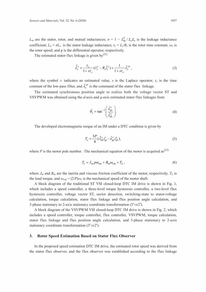
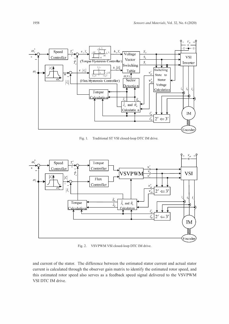
where Jm and Bm are the inertia and viscous friction coefficient of the motor, respectively, TL is the load torque, and ωrm = (2/P)ωr is the mechanical speed of the motor shaft. A block diagram of the traditional ST VSI closed-loop DTC IM drive is shown in Fig. 1, which includes a speed controller, a three-level torque hysteresis controller, a two-level flux hysteresis controller, voltage vector ST, sector detection, switching-state to stator-voltage calculation, torque calculation, stator flux linkage and flux position angle calculation, and 3-phase stationary to 2-axis stationary coordinate transformation (3s3 2s s⇒2s). A block diagram of the VSVPWM VSI closed-loop DTC IM drive is shown in Fig. 2, which includes a speed controller, torque controller, flux controller, VSVPWM, torque calculation, stator flux linkage and flux position angle calculation, and 3-phase stationary to 2-axis stationary coordinate transformation (3s3 2s s⇒2s).
3. Rotor Speed Estimation Based on Stator Flux Observer
In the proposed speed estimation DTC IM drive, the estimated rotor speed was derived from the stator flux observer, and the flux observer was established according to the flux linkage
1958 Sensors and Materials, Vol. 32, No. 6 (2020)
and current of the stator. The difference between the estimated stator current and actual stator current is calculated through the observer gain matrix to identify the estimated rotor speed, and this estimated rotor speed also serves as a feedback speed signal delivered to the VSVPWM VSI DTC IM drive.
Fig. 1. Traditional ST VSI closed-loop DTC IM drive.
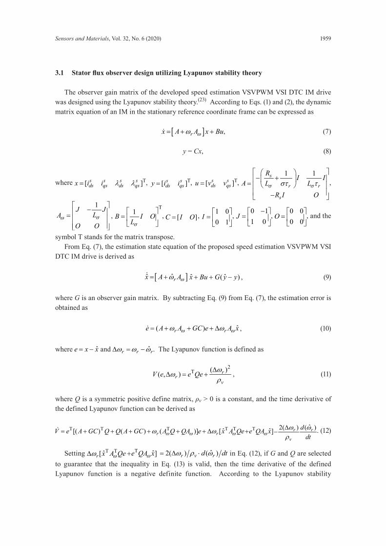
The observer gain matrix of the developed speed estimation VSVPWM VSI DTC IM drive was designed using the Lyapunov stability theory.(23) According to Eqs. (1) and (2), the dynamic matrix equation of an IM in the stationary reference coordinate frame can be expressed as
[ ]rx A A x Buωω= + + , (7)
y = Cx, (8)
where T[ ]s s s sds qs ds qsx i i λ λ= , T[ ]s s
ds qsy i i= , T[ ]s sds qsu v v= ,
1 1s
r r
s
R I IA L L
R I Oσ σστ τ
− + = −
,
1J JLA
O Oσω
− =
, T
1B I OLσ
=
, [ ]C I O= , 1 00 1
I =
, 0 11 0
J−
=
, 0 00 0
O =
, and the
symbol T stands for the matrix transpose. From Eq. (7), the estimation state equation of the proposed speed estimation VSVPWM VSI DTC IM drive is derived as
[ ]ˆˆ rx A Aωω= + x̂ Bu+ + ˆ( )G y y− , (9)
where G is an observer gain matrix. By subtracting Eq. (9) from Eq. (7), the estimation error is obtained as
ˆ( )r re A A GC e A xω ωω ω= + + + ∆ , (10)
where ˆe x x= − and ˆr r rω ω ω∆ = − . The Lyapunov function is defined as
2
T ( )( , ) rr
vV e e Qe ωω
ρ∆
∆ = + , (11)
where Q is a symmetric positive define matrix, ρv > 0 is a constant, and the time derivative of the defined Lyapunov function can be derived as
T T T T Tˆ[( ) ( ) ( )] [r rV e A GC Q Q A GC A Q QA e x A Qeω ω ωω ω= + + + + + + ∆
T ˆ]e QA xω+ˆ2( ) ( )r r
v
ddt
ω ωρ∆
− . (12)
Setting T Tˆ[r x A Qeωω∆ T ˆ]e QA xω+ ˆ2( ) ( )r v rd dtω ρ ω= ∆ ⋅ in Eq. (12), if G and Q are selected to guarantee that the inequality in Eq. (13) is valid, then the time derivative of the defined Lyapunov function is a negative definite function. According to the Lyapunov stability
1960 Sensors and Materials, Vol. 32, No. 6 (2020)
theory, the estimation error is asymptotically stable and the developed stator flux observer is asymptotically stable.
T T( ) ( ) ( ) 0rA GC Q Q A GC A Q QAω ωω+ + + + + < (13)
The adaptive law is
Tˆ( ) ˆrd e QA xdt ωω
= . (14)
From Eq. (14), the estimation rotor speed is derived as
T
T ˆ[ ]ˆ ˆ[ ] ir p
K e QA xK e QA xs
λ ωλ ωω = + , (15)
where Kpλ and Kiλ are the adaptation gains.
3.2 ObservergainmatrixdesignusingPSOalgorithm
The modified PSO algorithm is utilized to acquire the gain matrix of the designed stator flux observer.(24) In the modified PSO algorithm, the velocity and position of each particle are updated by applying an iterative procedure. The best solution can be acquired by a periodic computation until the termination condition is satisfied or the maximum number of iterations is reached. The updated velocity and position of the particle are given as follows.
1 2( 1) ( ) ( ) ( )i i best i best iv k v k rand P x rand G xγ γ+ = + ⋅ ⋅ − + ⋅ ⋅ − (16)
, if ( 1)
( 1), if ( 1)
max i maxi
min i min
v v k vv k
v v k v+ ≥
+ = + ≤ (17)
( 1) ( ) ( 1)i i ix k x k v k+ = + + (18)
, if
0.01 , ifmax i max
ii min
x rand x xx
rand x x⋅ ≥
= ⋅ ≤ (19)
Here, vi(k) and xi(k) are the present velocity and position of the particle; vi(k + 1) and xi(k + 1)are the next velocity and position of the particle; Pbest and Gbest are the best positions of the individual particle and swarm; γ1 and γ2 are the learning factors of the individual particle and swarm, and rand ∈ (0, 1], respectively. vmax and vmin are the prescribed maximum and minimum velocities of the particle (a larger vmax gives a better global search and a smaller vmin gives superior convergence of local searching ), and xmax and xmin are the prescribed maximum and minimum positions of the particle, respectively.
Sensors and Materials, Vol. 32, No. 6 (2020) 1961
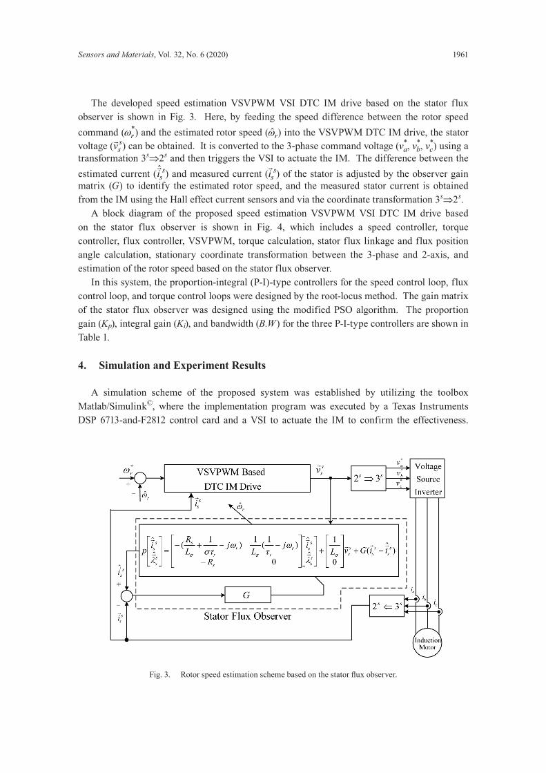
The developed speed estimation VSVPWM VSI DTC IM drive based on the stator flux observer is shown in Fig. 3. Here, by feeding the speed difference between the rotor speed command ( *
rω ) and the estimated rotor speed ( ˆrω ) into the VSVPWM DTC IM drive, the stator voltage ( s
sv ) can be obtained. It is converted to the 3-phase command voltage ( *av , *
bv , *cv ) using a
transformation 3s3 2s s⇒2s and then triggers the VSI to actuate the IM. The difference between the estimated current ( ˆ s
si
) and measured current ( ssi
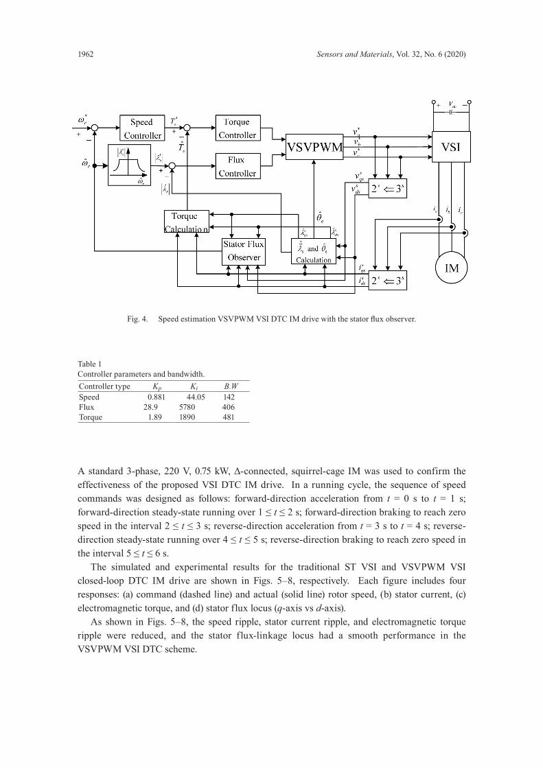
) of the stator is adjusted by the observer gain matrix (G) to identify the estimated rotor speed, and the measured stator current is obtained from the IM using the Hall effect current sensors and via the coordinate transformation 3s3 2s s⇒2s. A block diagram of the proposed speed estimation VSVPWM VSI DTC IM drive based on the stator flux observer is shown in Fig. 4, which includes a speed controller, torque controller, flux controller, VSVPWM, torque calculation, stator flux linkage and flux position angle calculation, stationary coordinate transformation between the 3-phase and 2-axis, and estimation of the rotor speed based on the stator flux observer. In this system, the proportion-integral (P-I)-type controllers for the speed control loop, flux control loop, and torque control loops were designed by the root-locus method. The gain matrix of the stator flux observer was designed using the modified PSO algorithm. The proportion gain (Kp), integral gain (Ki), and bandwidth (B.W) for the three P-I-type controllers are shown in Table 1.
Fig. 3. Rotor speed estimation scheme based on the stator flux observer.
1962 Sensors and Materials, Vol. 32, No. 6 (2020)
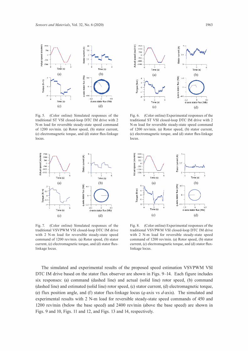
A standard 3-phase, 220 V, 0.75 kW, Δ-connected, squirrel-cage IM was used to confirm the effectiveness of the proposed VSI DTC IM drive. In a running cycle, the sequence of speed commands was designed as follows: forward-direction acceleration from t = 0 s to t = 1 s; forward-direction steady-state running over 1 ≤ t ≤ 2 s; forward-direction braking to reach zero speed in the interval 2 ≤ t ≤ 3 s; reverse-direction acceleration from t = 3 s to t = 4 s; reverse-direction steady-state running over 4 ≤ t ≤ 5 s; reverse-direction braking to reach zero speed in the interval 5 ≤ t ≤ 6 s. The simulated and experimental results for the traditional ST VSI and VSVPWM VSI closed-loop DTC IM drive are shown in Figs. 5–8, respectively. Each figure includes four responses: (a) command (dashed line) and actual (solid line) rotor speed, (b) stator current, (c) electromagnetic torque, and (d) stator flux locus (q-axis vs d-axis). As shown in Figs. 5–8, the speed ripple, stator current ripple, and electromagnetic torque ripple were reduced, and the stator flux-linkage locus had a smooth performance in the VSVPWM VSI DTC scheme.
Fig. 4. Speed estimation VSVPWM VSI DTC IM drive with the stator flux observer.
Table 1Controller parameters and bandwidth.Controller type Kp Ki B.WSpeedFluxTorque
0.88128.9
1.89
44.0557801890
142406481
Sensors and Materials, Vol. 32, No. 6 (2020) 1963
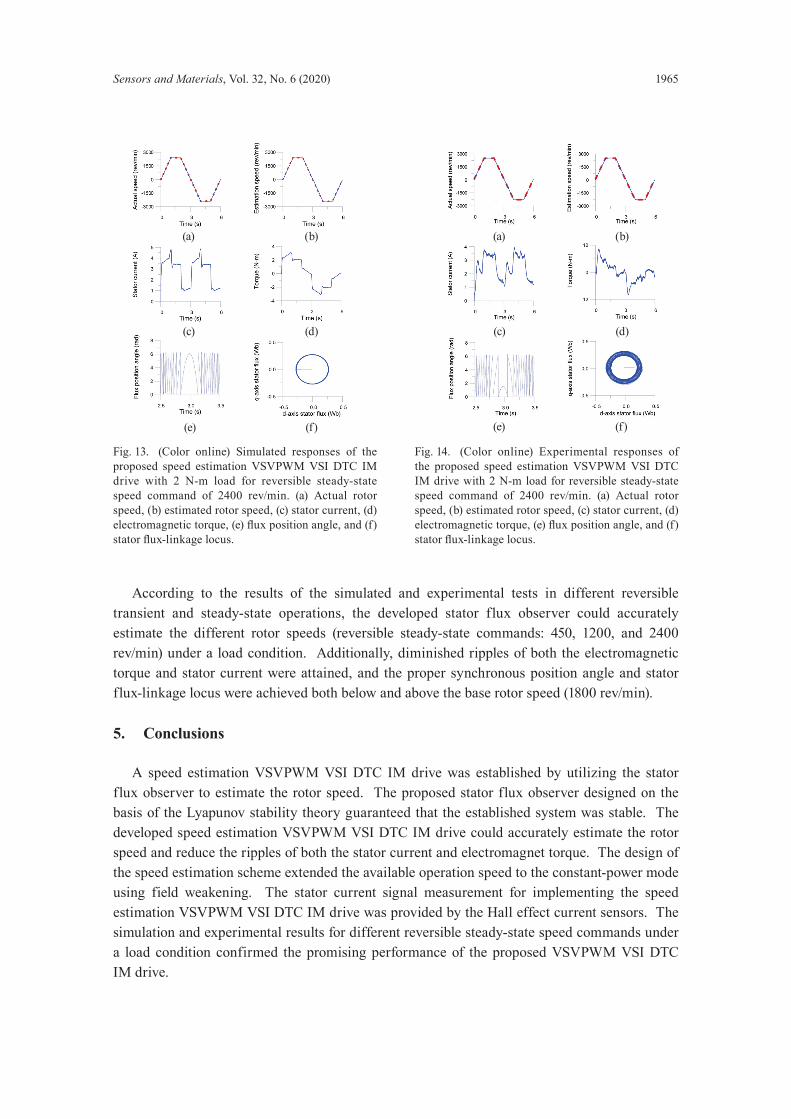
The simulated and experimental results of the proposed speed estimation VSVPWM VSI DTC IM drive based on the stator flux observer are shown in Figs. 9–14. Each figure includes six responses: (a) command (dashed line) and actual (solid line) rotor speed, (b) command (dashed line) and estimated (solid line) rotor speed, (c) stator current, (d) electromagnetic torque, (e) flux position angle, and (f) stator flux-linkage locus (q-axis vs d-axis). The simulated and experimental results with 2 N-m load for reversible steady-state speed commands of 450 and 1200 rev/min (below the base speed) and 2400 rev/min (above the base speed) are shown in Figs. 9 and 10, Figs. 11 and 12, and Figs. 13 and 14, respectively.
Fig. 5. (Color online) Simulated responses of the traditional ST VSI closed-loop DTC IM drive with 2 N-m load for reversible steady-state speed command of 1200 rev/min. (a) Rotor speed, (b) stator current, (c) electromagnetic torque, and (d) stator flux-linkage locus.
Fig. 6. (Color online) Experimental responses of the traditional ST VSI closed-loop DTC IM drive with 2 N-m load for reversible steady-state speed command of 1200 rev/min. (a) Rotor speed, (b) stator current, (c) electromagnetic torque, and (d) stator flux-linkage locus.
Fig. 7. (Color online) Simulated responses of the traditional VSVPWM VSI closed-loop DTC IM drive with 2 N-m load for reversible steady-state speed command of 1200 rev/min. (a) Rotor speed, (b) stator current, (c) electromagnetic torque, and (d) stator flux-linkage locus.
Fig. 8. (Color online) Experimental responses of the traditional VSVPWM VSI closed-loop DTC IM drive with 2 N-m load for reversible steady-state speed command of 1200 rev/min. (a) Rotor speed, (b) stator current, (c) electromagnetic torque, and (d) stator flux-linkage locus.
(a) (b)
(c) (d)
(a) (b)
(c) (d)
(a) (b)
(c) (d)
(a) (b)
(c) (d)
1964 Sensors and Materials, Vol. 32, No. 6 (2020)
Fig. 9. (Color online) Simulated responses of the proposed speed estimation VSVPWM VSI DTC IM drive with 2 N-m load for reversible steady-state speed command of 450 rev/min. (a) Actual rotor speed, (b) estimated rotor speed, (c) stator current, (d) electromagnetic torque, (e) flux position angle, and (f) stator flux-linkage locus.
Fig. 10. (Color online) Experimental responses of the proposed speed estimation VSVPWM VSI DTC IM drive with 2 N-m load for reversible steady-state speed command of 450 rev/min. (a) Actual rotor speed, (b) estimated rotor speed, (c) stator current, (d) electromagnetic torque, (e) flux position angle, and (f) stator flux-linkage locus.
Fig. 11. (Color online) Simulated responses of the proposed speed estimation VSVPWM VSI DTC IM drive with 2 N-m load for reversible steady-state speed command of 1200 rev/min. (a) Actual rotor speed, (b) estimated rotor speed, (c) stator current, (d) electromagnetic torque, (e) flux position angle, and (f) stator flux-linkage locus.
Fig. 12. (Color online) Experimental responses of the proposed speed estimation VSVPWM VSI DTC IM drive with 2 N-m load for reversible steady-state speed command of 1200 rev/min. (a) Actual rotor speed, (b) estimated rotor speed, (c) stator current, (d) electromagnetic torque, (e) flux position angle, and (f) stator flux-linkage locus.
(a) (b)
(c) (d)
(e) (f)
(a) (b)
(c) (d)
(e) (f)
(a) (b)
(e) (f)
(c) (d)
(a) (b)
(c) (d)
(e) (f)
Sensors and Materials, Vol. 32, No. 6 (2020) 1965
According to the results of the simulated and experimental tests in different reversible transient and steady-state operations, the developed stator flux observer could accurately estimate the different rotor speeds (reversible steady-state commands: 450, 1200, and 2400 rev/min) under a load condition. Additionally, diminished ripples of both the electromagnetic torque and stator current were attained, and the proper synchronous position angle and stator flux-linkage locus were achieved both below and above the base rotor speed (1800 rev/min).
5. Conclusions
A speed estimation VSVPWM VSI DTC IM drive was established by utilizing the stator flux observer to estimate the rotor speed. The proposed stator flux observer designed on the basis of the Lyapunov stability theory guaranteed that the established system was stable. The developed speed estimation VSVPWM VSI DTC IM drive could accurately estimate the rotor speed and reduce the ripples of both the stator current and electromagnet torque. The design of the speed estimation scheme extended the available operation speed to the constant-power mode using field weakening. The stator current signal measurement for implementing the speed estimation VSVPWM VSI DTC IM drive was provided by the Hall effect current sensors. The simulation and experimental results for different reversible steady-state speed commands under a load condition confirmed the promising performance of the proposed VSVPWM VSI DTC IM drive.
Fig. 13. (Color online) Simulated responses of the proposed speed estimation VSVPWM VSI DTC IM drive with 2 N-m load for reversible steady-state speed command of 2400 rev/min. (a) Actual rotor speed, (b) estimated rotor speed, (c) stator current, (d) electromagnetic torque, (e) flux position angle, and (f) stator flux-linkage locus.
Fig. 14. (Color online) Experimental responses of the proposed speed estimation VSVPWM VSI DTC IM drive with 2 N-m load for reversible steady-state speed command of 2400 rev/min. (a) Actual rotor speed, (b) estimated rotor speed, (c) stator current, (d) electromagnetic torque, (e) flux position angle, and (f) stator flux-linkage locus.
(a) (b) (a) (b)
(c) (d) (c) (d)
(e) (f) (e) (f)
1966 Sensors and Materials, Vol. 32, No. 6 (2020)
References
1 P. J. Koratkar and A. Sabnis: Proc. IEEE Intelligent Computing, Instrumentation and Control Technologies (2017) 831. https://doi.org/10.1109/ICICICT1.2017.8342672
2 B. R. Vinod and M. R. Baiju: Proc. IEEE Power Electronics, Drives and Energy Systems (2016) 1. https://doi.org/10.1109/PEDES.2016.7914353
3 A. Abdelkarim, B. Amor, and B. Abdelhamid: Proc. IEEE Electrical Engineering (2015) 1. https://doi.org/10.1109/INTEE.2015.7416602
4 G. Ramachandiran, S. Padmanaban, B. Frede O. Olorunfemi, and S. Veerana: IEEE Trans. Pow. Electron. 30 (2015) 6472. https://doi.org/10.1109/TPEL.2015.2429591
5 D. Kouchih, M. Tadjine, and M. S. Boucherit: Proc. IEEE Sciences and Techniques of Automatic Control & Computer Engineering (2013) 493. https://doi.org/10.1109/STA.2013.6783187
6 Y. Zhang, J. Zhu, Z. Zhao, W. Xu, and D. G. Dorrell: IEEE Trans. Pow. Electron. 27 (2013) 1502. https://doi.org/10.1109/TPEL.2010.2043543
7 Z. Zhang, R. Tang, B. Bai, and D. Xie: IEEE Trans. Mag. 46 (2010) 3133. https://doi.org/10.1109/TMAG.2010.2051142
8 M. A. Mossa, and S. Bolognani: Proc. IEEE Middle East Power Systems (2017) 385. https://doi.org/10.1109/MEPCON.2017.8301209
9 M. H. Holakooie, M. Ojaghi, and A. Taheri: IEEE Trans. Ind. Electron. 65 (2018) 7685. https://doi.org/10.1109/TIE.2018.2807410
10 Y. Guo, X. Wang, Y. Guo, and W. Deng: IET J. Eng. 2018 (2018) 432. https://doi.org/10.1049/joe.2018.0016 11 L. Zheng, J. E. Fletcher, B. W. Williams, and X. He: IEEE Trans. Ind. Electron. 58 (2011) 503. https://doi.
org/10.1109/TIE.2010.2047830 12 A. Ouchatti, A. Abbou, M. Akherraz, and A. Taouni: Proc. IEEE Renewable and Sustainable Energy (2014)
366. https://doi.org/10.1109/IRSEC.2014.7059752 13 A. Bennassar, A. Abbou, M. Akherraz, M. Barara, A. Essalmi, and Y. Zahraoui: Proc. IEEE Renewable and
Sustainable Energy (2014) 487. https://doi.org/10.1109/IRSEC.2014.7059800 14 P. Ponce, A. Molina, and A. Tellez: Proc. IEEE Caribbean Devices, Circuits and Systems (2014) 1. https://doi.
org/10.1109/ICCDCS.2014.7016166 15 Y. Sayouti, A. Abbou, M. Akherraz, and H. Mahmoudi: Proc. IEEE Power Engineering Energy Electrical
Drive (2011) 1. https://doi.org/10.1109/PowerEng.2011.6036501 16 R. Dadkhah, H. Givi, and A. Mehdipour: Proc. IEEE Power Electronics, Drive Systems and Technologies (2015)
137. https://doi.org/10.1109/PEDSTC.2015.7093263 17 I. M. Alsofyani, and N. R. N. Idris: IEEE Trans. Ind. Inform. 12 (2016) 1412. https://doi.org/10.1109/
TII.2016.2571682 18 I. M. Alsofyani, and N. R. N. Idris: IEEE Trans. Pow Electron. 31 (2016) 3027. https://doi.org/10.1109/
TPEL.2015.2447731 19 X. Wang: Proc. IEEE Energy Conversion Congress and Exposition (2017) 1331. https://doi.org/10.1109/
ECCE.2017.8095944 20 Y. C. Luo and W. X. Chen: Comp. Math. Appl. 64 (2012) 1206. https://doi.org/10.1016/j.camwa.2012.03.064 21 C. H. Liu: Control of AC Electrical Machines (Tunghua, Taipei, 2008) 4th ed., Chap. 5 (in Chinese). 22 Y. C. Luo, B. W. Chen, W. C. Pu, and N. S. Pai: Sens. Mater. 32 (2020) 239. https://doi.org/10.18494/
SAM.2020.2574 23 Y. C. Luo, Y. H. Chen, and Y. P. Kuo: Sens. Mater. 31 (2019) 165. https://doi.org/10.18494/SAM.2019.2020 24 Y. C. Luo and W. A. Huang: Low Freq. Noi . Vibr. Act . Cont r. 38 (2019) 69. ht t ps: //doi .
org/10.1177/1461348418824942
AbouttheAuthors
Yung-ChangLuo received his M.S. and Ph.D. degrees from National Taiwan University of Science and Technology, Taipei, Taiwan, ROC, in 1991 and 2000, respectively. He is currently a professor in the Department of Electrical Engineering, National Chin-Yi University of Technology, Taichung, Taiwan, ROC. His current research interests include the speed estimation of ac motor drives, the front-end power factor correction of converters, and the design of microcontroller-based motor drives. ([email protected])
Sensors and Materials, Vol. 32, No. 6 (2020) 1967
Xu-HongZheng was born in 1996. He is a master’s student at the Department of Electrical Engineering, National Chin-Yi University of Technology, Taichung, Taiwan. His research mainly focuses on FVC IM drives.
Chien-HuaLiaoreceived his M.S. degree from the Department of Electrical Engineering, National Chin-Yi University of Technology, Taichung, Taiwan, in 2018. His research mainly focuses on speed estimation DTC IM drives.
Ying-Piao Kuo received his B.S. degree in electrical engineering in 1985 from National Taiwan University of Science and Technology, Taipei, Taiwan, his M.S. degree in electrical engineering in 1989 from National Taiwan University, and his Ph.D. degree from National Taiwan University of Science and Technology in 2011. In 1989, he joined National Chin-Yi University of Technology, Taichung, Taiwan, where he is currently an associate professor in the Department of Electrical Engineering. His current research interests include the design of switching-mode power supplies, partial discharge, and power system stability. ([email protected])