DIRECT VENT COUNTERFLOW WALL FURNACE INSTALLATION AND OPERATING INSTRUCTIONS P/N 72900 - REV. 04/2013 WARNING: If the information in this manual is not followed exactly, a fire or explosion may result causing property damage, personal injury or loss of life. - Do not store or use gasoline or other flammable vapors and liquids in the vicinity of this or any other appliance. - WHAT TO DO IF YOU SMELL GAS: - Do not try to light any appliance. - Do not touch any electrical switch; do not use any phone in your building. - Immediately call your gas supplier from a neighbor’s phone. Follow the gas supplier’s instructions. - If you cannot reach your gas supplier, call the fire department. - INSTALLATION AND SERVICE MUST BE PERFORMED BY A QUALIFIED INSTALLER, SERVICE AGENCY OR THE GAS SUPPLIER. R R MODEL NUMBERS NAT. GAS DVCF403C-H DVCF553C-H L.P. GAS DVCF404C-H DVCF554C-H 24 VOLT SYSTEM WITH LOW-BTU PILOT MODEL NUMBERS NAT. GAS DVCF407C-H DVCF557C-H L.P. GAS DVCF408C-H DVCF558C-H 24 VOLT SYSTEM W/INTERMITTENT IGNITION (IID) The coating selected to provide longer life to the heat exchanger may smoke slightly upon initial firing. Please provide adequate ventilation if this occurs. INST ALLER: Leave this manual with the appliance. CONSUMER: Retain this manual for future reference. WARNING: Operation of this furnace without the properly installed, furnished vent system and vent cap could result in Carbon Monoxide (CO) poisoning and possible death. For your safety, this furnace and the vent system should be inspected at least annually by a qualified service technician. Installation, maintenance, service, troubleshooting and repairs must be performed by a qualified service agency. Mr./Mrs. Homeowner, DO NOT attempt any of these procedures yourself as this could expose you to property damage, personal injury or loss of life and will invalidate all warranties. This unit is for residential use only and is not approved for installation in greenhouses, or environ- ments involving dusty, wet, corrosive, or explosive conditions. Such conditions will invalidate the warranty and may create unsafe conditions.
Transcript
DIRECT VENTCOUNTERFLOWWALL FURNACE
INSTALLATION ANDOPERATING INSTRUCTIONS
P/N 72900 - REV. 04/2013
WARNING: If the information in this manual is not followed exactly, afire or explosion may result causing property damage, personal injury orloss of life.
- Do not store or use gasoline or other flammable vapors and liquidsin the vicinity of this or any other appliance.
- WHAT TO DO IF YOU SMELL GAS:
- Do not try to light any appliance.- Do not touch any electrical switch; do not use any phone in your
building.- Immediately call your gas supplier from a neighbor’s phone. Follow the
gas supplier’s instructions.- If you cannot reach your gas supplier, call the fire department.
- INSTALLATION AND SERVICE MUST BE PERFORMED BY AQUALIFIED INSTALLER, SERVICE AGENCY OR THE GASSUPPLIER.
R R
MODEL NUMBERSNAT. GAS DVCF403C-H DVCF553C-HL.P. GAS DVCF404C-H DVCF554C-H
24 VOLT SYSTEM WITH LOW-BTU PILOT MODEL NUMBERSNAT. GAS DVCF407C-H DVCF557C-HL.P. GAS DVCF408C-H DVCF558C-H
24 VOLT SYSTEM W/INTERMITTENT IGNITION (IID)
The coating selected to provide longer life tothe heat exchanger may smoke slightly upon
initial firing. Please provide adequateventilation if this occurs.
INSTALLER: Leave this manual with theappliance.
CONSUMER: Retain this manual forfuture reference.
WARNING: Operation of this furnace without the properly installed, furnished vent system and vent capcould result in Carbon Monoxide (CO) poisoning and possible death. For your safety, this furnace and thevent system should be inspected at least annually by a qualified service technician.
Installation, maintenance, service, troubleshooting and repairs must be performed by a qualified serviceagency. Mr./Mrs. Homeowner, DO NOT attempt any of these procedures yourself as this could expose youto property damage, personal injury or loss of life and will invalidate all warranties.
This unit is for residential use only and is not approved for installation in greenhouses, or environ-ments involving dusty, wet, corrosive, or explosive conditions. Such conditions will invalidate thewarranty and may create unsafe conditions.
INTRODUCTIONRead these installation and operating instructions carefully before you install or attempt to use this Direct VentCounterflow Wall Furnace. If you do not understand any part of the instructions, consult local authorities, aqualified installer, service technician or the gas supplier. FAILURE TO READ OR UNDERSTAND THESEINSTRUCTIONS CAN RESULT IN MALFUNCTION, INEFFICIENT OPERATION, PROPERTYDAMAGE, SERIOUS INJURY OR DEATH.
SPECIFICATIONS AND DIMENSIONSYour Direct Vent Counterflow Wall Furnace is shipped in two cartons. One carton contains the furnace, thermostat,thermostat wire and insulated staples. The second carton will have the vent tube, air intake tube and vent capassembly. After the furnace has been removed from the carton check the rating plate to verify that the modelnumber is correct and that the wall furnace is equipped with the type gas you intend to use.
Page 2
Model Type Type Btu/Hr. Gas Blower Approx.Number Control Gas Input Inlet Finished Dimensions Speed Amps CFM Ship. Wt.
24 VOLT SYSTEM WITH LOW-BTU STANDING PILOTDVCF403C-H 24 Volt Nat. 40,000 ½” 14-5/16”Wx78-5/8”Hx11-3/4”D 1 1.95 320 130 Lbs.DVCF404C-H 24 Volt L.P. 40,000 ½” 14-5/16”Wx78-5/8”Hx11-3/4”D 1 1.95 320 130 Lbs.DVCF553C-H 24 Volt Nat. 55,000 ½” 14-5/16”Wx87-5/16”Hx11-3/4”D 2 3.05 440 144 Lbs.DVCF554C-H 24 Volt L.P. 55,000 ½” 14-5/16”Wx87-5/16”Hx11-3/4”D 2 3.05 440 144 Lbs.
24 VOLT SYSTEM WITH INTERMITTENT IGNITION (I.I.D.)DVCF407C-H 24 Volt Nat. 40,000 ½” 14-5/16”Wx78-5/8”Hx11-3/4”D 1 2.2 320 130 Lbs.DVCF408C-H 24 Volt L.P. 40,000 ½” 14-5/16”Wx78-5/8”Hx11-3/4”D 1 2.25 320 130 Lbs.DVCF557C-H 24 Volt Nat. 55,000 ½” 14-5/16”Wx87-5/16”Hx11-3/4”D 2 3.3 440 144 Lbs.DVCF558C-H 24 Volt L.P. 55,000 ½” 14-5/16”Wx87-5/16”Hx11-3/4”D 2 3.35 440 144 Lbs.
The State of Massachusetts requires that installation and service of a gas appliance beperformed by a plumber or gas fitter licensed in the Commonwealth of Massachusetts.
The appliance may be installed in an aftermarket permanently located, manufactured (mobile)home, where not prohibited by local codes. This appliance is only for use with the type of gas
indicated on the rating plate. This appliance is not convertible for use with other gases, unless acertified kit is used.
SAFETY RULES
1. This appliance must be installed in accordance with local codes, if any; if not, follow the National Fuel GasCode, ANSI Z223.1/NFPA 54 or the Natural Gas and Propane Installation Code, CSA-B149.1.
2. Follow all applicable local codes and ordinances. If there are none, follow the latest edition of the NationalFuel Gas Code, ANSI.Z223.1. A copy may be obtained from American Gas Association, 1515 WilsonBlvd., Arlington, Virginia 22209, or the National Fire Protection Association, Batterymarch Park, Quincy,MA. 02269. In Canada, see the current CAN1-B149 installation code, available from International ApprovalServices, 55 Scarsdale Road, Don Mills, Ontario, Canada M3B-2R3.
3. The appliance, when installed, must be electrically grounded in accordance with local codes or, in the absenceof local codes, with the latest edition of National Electrical Code, ANSI/NFPA70. In Canada, see the currentCSA C22.2 Canadian Electrical Code, available from International Approval Services, 178 Rexdale Boulevard,Etobicoke, Ontario, Canada M9W 1R3.
4. Do not install this furnace in a recreational vehicle or trailer.5. Do not operate this furnace unless it is connected to the supplied vent system with vent cap in place. Do not
attempt to extend vent pipes. 12 inches is maximum length.6. Never use a match, candle, flame or other source of ignition to check for gas leaks. Use only soapy water or
liquid detergent.7. Before cleaning or servicing, turn off the gas and allow furnace to cool.8. Do not operate furnace without grilles and front panel in place.9. Due to high temperatures, locate furnace out of traffic and away from furniture and drapes.10. Children and adults should be alerted to the hazard of high surface temperature and should be kept away to
avoid burns or clothing ignition.11. Young children should be carefully supervised when they are in the same room with the furnace.12. Do not place clothing or other flammable material on or near the furnace.13. Installation and repair should be done by a qualified service technician. The furnace should be inspected
before use and at least annually by a professional service technician. More frequent cleaning may be requireddue to excessive lint from carpeting, bedding material, etc. It is imperative that control compartments, burners,and circulating air passageways of the furnace be kept clean.
14. Do not put anything around the furnace or vent cap that will obstruct the flow of combustion and ventilation air.15. When installing the furnace allow adequate accessibility clearances for servicing and proper operation. (See
Figure 1 – Page 5).16. The wall furnace should be located near the center of the area to be heated for optimal heat distribution.
If the wall furnace is installed directly on carpeting, tile or any combustible material other than wood flooring,the wall furnace shall be installed on a metal plate or wood panel secured to the floor, extending the full widthand depth of the wall furnace. If a side register kit is to be installed, see Page 14.
17. Do not use this heater if any part has been under water. Immediately call a qualified service technician toinspect the heater and to replace any part of the control system which has been under water.
18. For your safety, this furnace is equipped with a manual reset auxiliary limit switch. In case of failure by theprimary limit switch, this switch will shut the valve down completely before unsafe temperatures are reached.After a cool down period, switch must be manually reset. If outages persist, call a qualified service person.
19. Side discharge kit boots must not exceed 10 inches.20. Locate the auxiliary limit switch and push in the red reset button. This will reset the switch in case it accidentally
opened during shipping.
Page 3
Vent Terminal Air Supply Inlet Area where terminal is not permitted
VENT TERMINAL CLEARANCES
Page 4
REFERENCE LETTER TO DRAWING
CANADIAN INSTALLATIONS¹ U.S. INSTALLATIONS²
A = Clearance above grade, veranda, porch, deck, or balcony
12 Inches (30 cm) 12 Inches (30 cm)
B = Clearance to window or door that may be opened
D = Vertical clearance to ventilated soffit located above the terminal within a horizontal distance of 2 Feet (61 cm) from the center line of the terminal
18 Inches (46 cm) 18 Inches (46 cm)
E = Clearance to unventilated soffit 24 Inches (61 cm) 24 Inches (61 cm) F = Clearance to outside corner 12 Inches (30 cm) 12 Inches (30 cm) G = Clearance to inside corner 12 Inches (30 cm) 12 Inches (30 cm) H = Clearance to each side of center line extended above meter/ regulator assembly
3 Feet (91 cm) within a height 15 Feet (4.5m) above the meter/regulator assembly
Clearance in accordance with local installation codes and the requirements of the gas supplier
I = Clearance to service regulator vent outlet
3 Feet (91 cm) Clearance in accordance with local installation codes and the requirements of the gas supplier
J = Clearance to nonmechanical air supply inlet to building or the combustion air inlet to any other appliance
6 Feet (1.83 m) 3 Feet (91 cm) above if within 10 Feet (3 m) horizontally
L = Clearance above paved sidewalk or paved driveway located on public property
7 Feet (2.13m) A vent shall not terminate directly above a sidewalk or paved driveway that is located between two single family dwellings and serves both dwellings.
Clearance in accordance with local installation codes and the requirements of the gas supplier.
M = Clearance under veranda, porch, deck, or balcony
12 Inches (30 cm) permitted only if veranda, porch, deck, or balcony is fully open on a minimum of two sides.
Clearance in accordance with local installation codes and the requirements of the gas supplier.
¹ In accordance with the current CSA-B149.1 Natural Gas and Propane Installation Code ² In accordance with the current ANSI Z223.1 / NFPA 54 National Fuel Gas Code
CLEARANCES
1. The minimum clearance to a side wall is 4”. (See Fig. 1). NOTE:The unit may be recessed and rest directly against side studs andthe inside surface of the rear wall.
2. The minimum clearance to the ceiling is 4”. (See Figure 1).3. The minimum clearance to the floor is 0”. (See Figure 1).4. The minimum clearance from the side of the vent cap to any
protruding obstructions, or corners is 12”. (See Figure 2b).5. The minimum clearance from any window to the side of the vent
cap is 9” for DVCF403, 404, 407 and 408C (See Figure 2), and12” for DVCF553, 554, 557, and 558C (See Figure 2b).
6. The minimum clearance from any overhanging projection is 24”to top of vent cap (See Figure 2).
7. RESIDENTIAL GARAGE INSTALLATION: Gas utilizationequipment in residential garages shall be installed so that allburners and burner ignition devices are located not less than 18inches (46 cm) above the floor. Such equipment shall be located,or protected so it is not subject to damage by a moving vehicle.Use care in selecting a good location within the garage. DONOT locate the appliance where heated air will be directed ontoa nearby parked vehicle. Paint may discolor or rubber may hardenand crack. DO NOT allow heated discharge air to blow directlyonto open or closed containers of paint, gasoline or other liquidshaving flammable vapors.
Ceiling
4” Minimum
SIDE WALL4” Minimum
FLOOR 0”
FIGURE 1
24” Min.
12”Min.
12”Min.
12” Min.
FIGURE 2B / DVCF553C, 554C, 557C, AND 558C
24” Min.
12”Min.
12” Min.
9”Min.
FIGURE 2 / DVCF403C, 404C, 407C, AND 408C
Page 5
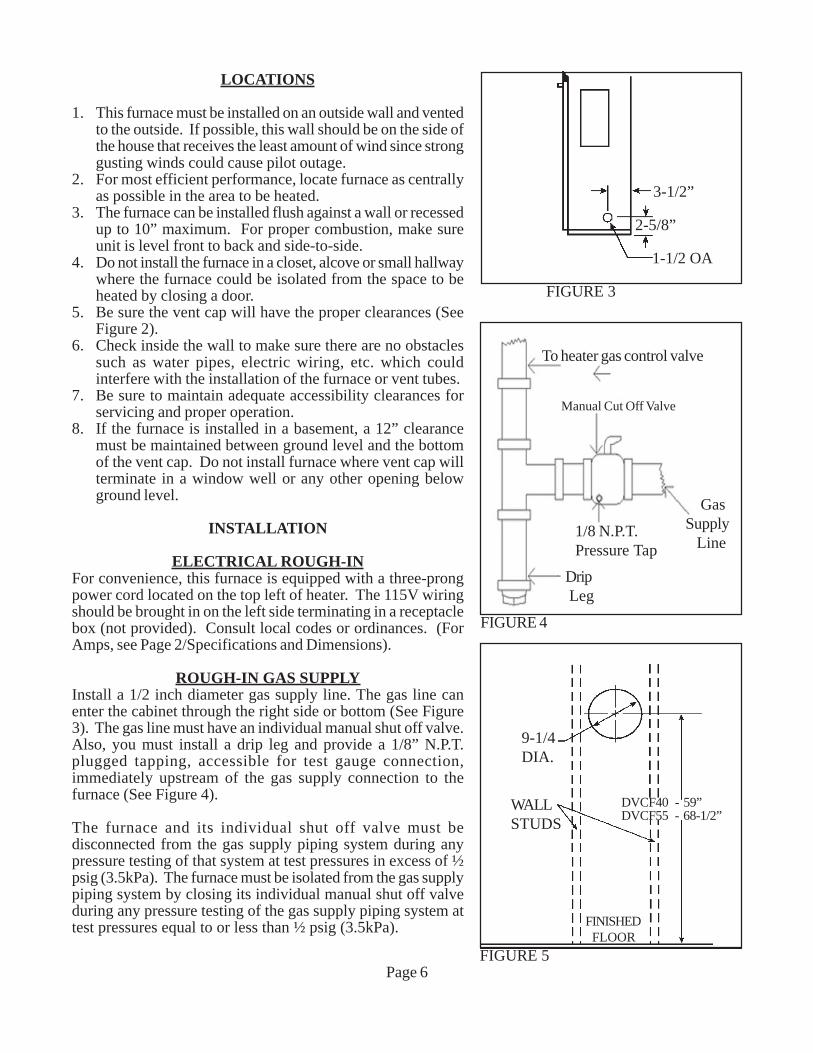
LOCATIONS
1. This furnace must be installed on an outside wall and ventedto the outside. If possible, this wall should be on the side ofthe house that receives the least amount of wind since stronggusting winds could cause pilot outage.
2. For most efficient performance, locate furnace as centrallyas possible in the area to be heated.
3. The furnace can be installed flush against a wall or recessedup to 10” maximum. For proper combustion, make sureunit is level front to back and side-to-side.
4. Do not install the furnace in a closet, alcove or small hallwaywhere the furnace could be isolated from the space to beheated by closing a door.
5. Be sure the vent cap will have the proper clearances (SeeFigure 2).
6. Check inside the wall to make sure there are no obstaclessuch as water pipes, electric wiring, etc. which couldinterfere with the installation of the furnace or vent tubes.
7. Be sure to maintain adequate accessibility clearances forservicing and proper operation.
8. If the furnace is installed in a basement, a 12” clearancemust be maintained between ground level and the bottomof the vent cap. Do not install furnace where vent cap willterminate in a window well or any other opening belowground level.
INSTALLATION
ELECTRICAL ROUGH-INFor convenience, this furnace is equipped with a three-prongpower cord located on the top left of heater. The 115V wiringshould be brought in on the left side terminating in a receptaclebox (not provided). Consult local codes or ordinances. (ForAmps, see Page 2/Specifications and Dimensions).
ROUGH-IN GAS SUPPLYInstall a 1/2 inch diameter gas supply line. The gas line canenter the cabinet through the right side or bottom (See Figure3). The gas line must have an individual manual shut off valve.Also, you must install a drip leg and provide a 1/8” N.P.T.plugged tapping, accessible for test gauge connection,immediately upstream of the gas supply connection to thefurnace (See Figure 4).
The furnace and its individual shut off valve must bedisconnected from the gas supply piping system during anypressure testing of that system at test pressures in excess of ½psig (3.5kPa). The furnace must be isolated from the gas supplypiping system by closing its individual manual shut off valveduring any pressure testing of the gas supply piping system attest pressures equal to or less than ½ psig (3.5kPa).
Page 6FIGURE 5
9-1/4DIA.
WALLSTUDS
DVCF40 - 59”DVCF55 - 68-1/2”
FINISHED FLOOR
FIGURE 3
3-1/2”
2-5/8”
1-1/2 OA
GasSupply Line
Drip Leg
Manual Cut Off Valve
1/8 N.P.T.Pressure Tap
FIGURE 4
To heater gas control valve
LOCATE VENT OPENING
After the location of the heater has been determined, theopening for the vent pipe should be cut. If the heater is to berecessed, cut out opening for heater between studs on theinterior wall and cut out the floor plate between the studs, soheater will set flat on floor as all dimensions are given froma finished floor. The height of the cut out for a 40,000 BTUmodel is 78-5/8”, for the 55,000 models the cut out height is87-5/16”. NOTE: This dimension may be increased to allowmore room for installation and making the wiring connection,then refinished.
Next, cut out a 9-1/4” opening in exterior wall for the venttubes to pass through. The center of opening for the 40,000BTU furnace is 59”, the center for opening for 55,000 BTUfurnace is 68-1/2”. See Figure 5, on Page 6.
If the heater is to be surfaced mounted, cut out 9-1/4” openingthrough the interior and exterior wall. The center of cut outwill be 59” for 40,000 BTU and 68-1/2” for 55,000 BTU models.Be sure both cutouts are level with each other.
INSTALLING THE FURNACE
The vent system supplied with this furnace will accommodatewalls ¾” (when recessed) up to 12” thick. Use only theexhaust tube, air intake tube and vent cap supplied withheater. Do not attempt to lengthen the exhaust or air intaketubes, this could cause an imbalance in the heater resultingin poor performance and pilot outage (See Figure 6).
Measure exact distance “X” between surface on which backof cabinet will rest (inside of recessed cavity or face of wallwhen freestanding) and the outside wall surface (see Figure6).
Inlet Air Tube “A” – Measuring from gasketed surface,mark and cut pipe same as dimension “X”. Remove anyburrs.
Vent Exhaust Tube “B” – Measuring from gasketedsurface, mark and cut pipe 1-3/4” greater than dimension“X”. Remove any burrs.
Fasten vent exhaust tube “B” to heat exchanger collar andInlet Air Tube “A” to flange on back of furnace using 16 #3/8 screws (“C”) provided. Be sure gaskets are in place andnot damaged. Anytime the vent pipes are removed checkand replace gaskets (if necessary). Failure to replace missingor damaged gaskets may expose homeowner to lifethreatening conditions.
Secure furnace in place using 2 holes provided in bottom ofcasing. NOTE: Make sure both tubes are centered in cutout. Slide the vent cap onto the pipes extending from theback of the furnace. A rotating or twisting motion will easethis installation. Secure vent cap and vent cap spacer plateto wall causing the vent tubes to have a slight downwardpitch. This will prevent water from entering. Anchors (notprovided) may be required. Caulk around vent cap spacerplate with caulking provided. NOTE: Some framing maybe necessary to provide a flat surface against the vent capspacer plate and to prevent rain from entering the wallopening.
GAS CONNECTION
Make the gas connection between the manual shut off valveand the furnace gas control valve with approved ½”connectors. Compounds used on threaded joints of gaspiping shall be approved for use with L.P. gas. The gaslines must be checked for leaks by the installer with soapywater or liquid detergent, never use an open flame. Ifconnections are not exposed, a pressure test must be run.Be sure to disconnect the gas supply line from the appliancevalve before pressure testing. The manifold pressure ispre-set at the factory and should be 3.5” w.c. for NaturalGas and 10” w.c. for L.P. Gas. The minimum inlet pressurefor Natural Gas is 4.5” w.c. and 11” w.c. for L.P. Gas, “forpurpose of input adjustment”. The maximum inlet pressureshould never exceed 7.0” w.c. on Natural Gas or 14” w.c.on L.P. Gas.
THERMOSTAT INSTALLATION
Follow the instructions included with the thermostat. Selecta location for the thermostat on an inside wall approximately5 feet above the floor where it won’t be affected by heat orcold sources such as direct sunlight, televisions, fireplaces,hidden hot or cold water pipes, drafts, etc., and a minimumof 4’ from the heater. The thermostat must never be placedin an adjacent room. Connect thermostat wires tothermostat and mount to wall. Run wire to furnace andmake connections to thermostat wires coming out of top offurnace. Use insulated staples (provided) to secure wire towall.
OPERATIONThis heater is equipped with a slow opening gas control. Ona call for heat the gas valve does not snap-open to fullmanifold pressure, but opens with a gradual increase tonormal manifold pressure. The time lapse from the call forheat to normal operating pressure is two to five seconds.The slow open feature assures a safe, less noisy ignition.
After the heat exchanger has warmed sufficiently, the fanwill automatically come on to efficiently transfer the heatinto the room. NOTE: The 40,000 BTU models have a onespeed and the 55,000 BTU models have a two-speedautomatic fan.
VentCap Vent Cap
SpacerPlate
HeatExchanger Collar
FIGURE 6
Page 7
LIGHTING INSTRUCTIONS: DVCF403C-H/404C-H, DVCF553C-H/554C-HFOR YOUR SAFETY READ BEFORE LIGHTING
WARNING: If you do not follow these instructions exactly, a fire or explosion may resultcausing property damage, personal injury or loss of life.
A. This appliance has a pilot which must be lighted byhand. When lighting the pilot, follow these instruc-tions exactly.
B. BEFORE LIGHTING, smell all around the appliancearea for gas. Be sure to smell next to the floor becausesome gas is heavier than air and will settle on thefloor.
WHAT TO DO IF YOU SMELL GAS:- Do not try to light any appliance.- Do not touch any electric switch, do not use any
phone in your building.- Immediately call your gas supplier from a neighbor’s
phone. Follow the gas supplier’s instructions.
- If you cannot reach your gas supplier, call the firedepartment.
C. Use only your hand to push in or turn the gas controlknob. Never use tools. If the knob will not push in or turnby hand, don’t try to repair it, call a qualified servicetechnician. Force or attempted repair may result in a fire orexplosion.
D. Do not use this appliance if any part has been under water.Immediately call a qualified service technician to inspectthe appliance and to replace any part of the control systemand any gas control which has been under water.
PN 91211 02/05
LIGHTING INSTRUCTIONS
TO TURN OFF GAS TO APPLIANCE
Page 8
6. Wait five (5) minutes to clear out any gas. Then smell forgas, including near the floor. If you smell gas, STOP!Follow “B” in the information on the safety label. If youdon’t smell gas, go to the next step.
7. Open sight glass cover.8. Locate red piezo ignitor button on side of gas control.
Locate pilot behind sight glass. (Follow metal pilot tubefrom gas control).
9. Turn gas control knob counterclockwise to “PILOT”.
10. Push in pilot control knob and hold in. Immediately begina series of pushing and releasing the red piezo ignitorbutton, while observing the pilot through the sight glass.Continue to spark until pilot is lit. Continue to hold thepilot control knob in for about one (1) minute after thepilot is lit. Release the pilot control knob and it will popback up. Pilot should remain lit. If pilot goes out, repeatsteps 4 thru 9.
- If knob does not pop up when released, STOP andimmediately call your service technician or gas supplier.
- If the pilot will not stay lit after several tries, turn the gascontrol knob to “OFF” and call your service technician orgas supplier.
11. Close sight glass cover.12. Turn gas control knob counterclockwise to “ON”.13. Replace lower front panel.14. Turn on all electric to the appliance.15. Set thermostat to desired setting.
PN 91211 02/05
1. Turn thermostat to it’s lowest setting.2. Turn off all electric power to the appliance if service is to be performed.3. Remove lower front panel.4. Push in gas control knob slightly and turn clockwise to “OFF”. Do not force.5. Replace lower front panel. PN 91211 02/05
Gas Control Knob
NOTE: Knobcan not beturned from“PILOT” to“OFF” unlessknob is pushedin slightly. Donot force.
Pilot Control Knob
1. STOP! Read the information on the safety label.2. Set thermostat to lowest setting.3. Turn off all electric power to the appliance.4. Remove lower front panel.5. Push in gas control knob slightly and turn clcockwise
to “OFF”.
LIGHTING INSTRUCTIONS: DVCF407C-H/408C-H, DVCF557C-H/558C-HFOR YOUR SAFETY READ BEFORE LIGHTING
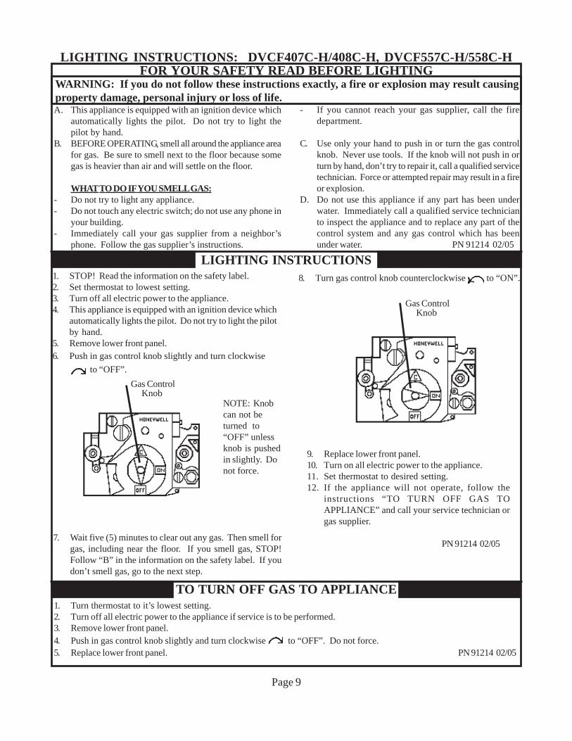
WARNING: If you do not follow these instructions exactly, a fire or explosion may result causingproperty damage, personal injury or loss of life.A. This appliance is equipped with an ignition device which
automatically lights the pilot. Do not try to light thepilot by hand.
B. BEFORE OPERATING, smell all around the appliance areafor gas. Be sure to smell next to the floor because somegas is heavier than air and will settle on the floor.
WHAT TO DO IF YOU SMELL GAS:- Do not try to light any appliance.- Do not touch any electric switch; do not use any phone in
your building.- Immediately call your gas supplier from a neighbor’s
phone. Follow the gas supplier’s instructions.
- If you cannot reach your gas supplier, call the firedepartment.
C. Use only your hand to push in or turn the gas controlknob. Never use tools. If the knob will not push in orturn by hand, don’t try to repair it, call a qualified servicetechnician. Force or attempted repair may result in a fireor explosion.
D. Do not use this appliance if any part has been underwater. Immediately call a qualified service technicianto inspect the appliance and to replace any part of thecontrol system and any gas control which has beenunder water. PN 91214 02/05
LIGHTING INSTRUCTIONS
TO TURN OFF GAS TO APPLIANCE
Page 9
1. Turn thermostat to it’s lowest setting.2. Turn off all electric power to the appliance if service is to be performed.3. Remove lower front panel.4. Push in gas control knob slightly and turn clockwise to “OFF”. Do not force.5. Replace lower front panel. PN 91214 02/05
Gas Control Knob
1. STOP! Read the information on the safety label.2. Set thermostat to lowest setting.3. Turn off all electric power to the appliance.4. This appliance is equipped with an ignition device which
automatically lights the pilot. Do not try to light the pilotby hand.
5. Remove lower front panel.6. Push in gas control knob slightly and turn clockwise
to “OFF”.
7. Wait five (5) minutes to clear out any gas. Then smell forgas, including near the floor. If you smell gas, STOP!Follow “B” in the information on the safety label. If youdon’t smell gas, go to the next step.
NOTE: Knobcan not beturned to“OFF” unlessknob is pushedin slightly. Donot force.
8. Turn gas control knob counterclockwise to “ON”.
9. Replace lower front panel.10. Turn on all electric power to the appliance.11. Set thermostat to desired setting.12. If the appliance will not operate, follow the
instructions “TO TURN OFF GAS TOAPPLIANCE” and call your service technician orgas supplier.
PN 91214 02/05
Gas Control Knob
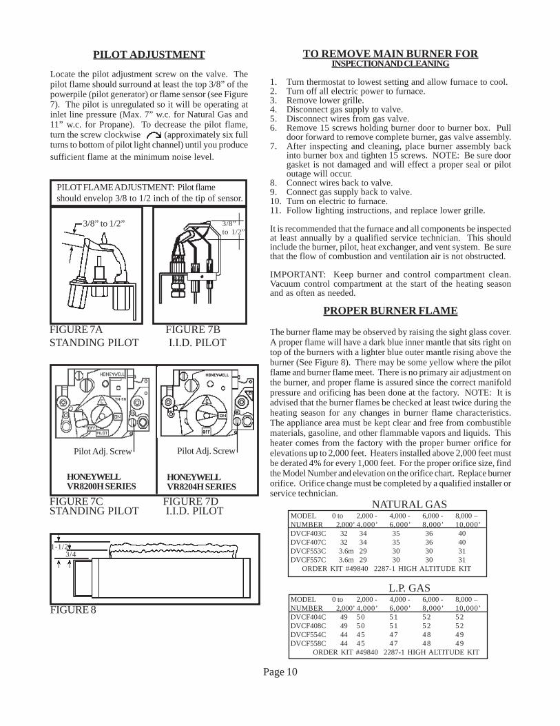
PILOT ADJUSTMENT
Locate the pilot adjustment screw on the valve. Thepilot flame should surround at least the top 3/8” of thepowerpile (pilot generator) or flame sensor (see Figure7). The pilot is unregulated so it will be operating atinlet line pressure (Max. 7” w.c. for Natural Gas and11” w.c. for Propane). To decrease the pilot flame,turn the screw clockwise (approximately six fullturns to bottom of pilot light channel) until you producesufficient flame at the minimum noise level.
TO REMOVE MAIN BURNER FORINSPECTION AND CLEANING
1. Turn thermostat to lowest setting and allow furnace to cool.2. Turn off all electric power to furnace.3. Remove lower grille.4. Disconnect gas supply to valve.5. Disconnect wires from gas valve.6. Remove 15 screws holding burner door to burner box. Pull
door forward to remove complete burner, gas valve assembly.7. After inspecting and cleaning, place burner assembly back
into burner box and tighten 15 screws. NOTE: Be sure doorgasket is not damaged and will effect a proper seal or pilotoutage will occur.
8. Connect wires back to valve.9. Connect gas supply back to valve.10. Turn on electric to furnace.11. Follow lighting instructions, and replace lower grille.
It is recommended that the furnace and all components be inspectedat least annually by a qualified service technician. This shouldinclude the burner, pilot, heat exchanger, and vent system. Be surethat the flow of combustion and ventilation air is not obstructed.
IMPORTANT: Keep burner and control compartment clean.Vacuum control compartment at the start of the heating seasonand as often as needed.
PROPER BURNER FLAME
The burner flame may be observed by raising the sight glass cover.A proper flame will have a dark blue inner mantle that sits right ontop of the burners with a lighter blue outer mantle rising above theburner (See Figure 8). There may be some yellow where the pilotflame and burner flame meet. There is no primary air adjustment onthe burner, and proper flame is assured since the correct manifoldpressure and orificing has been done at the factory. NOTE: It isadvised that the burner flames be checked at least twice during theheating season for any changes in burner flame characteristics.The appliance area must be kept clear and free from combustiblematerials, gasoline, and other flammable vapors and liquids. Thisheater comes from the factory with the proper burner orifice forelevations up to 2,000 feet. Heaters installed above 2,000 feet mustbe derated 4% for every 1,000 feet. For the proper orifice size, findthe Model Number and elevation on the orifice chart. Replace burnerorifice. Orifice change must be completed by a qualified installer orservice technician.
GAS VALVESparkSense24 V24 VGnd.Gnd(Burner)PVMV/PVMV
BL
AC
K BL
AC
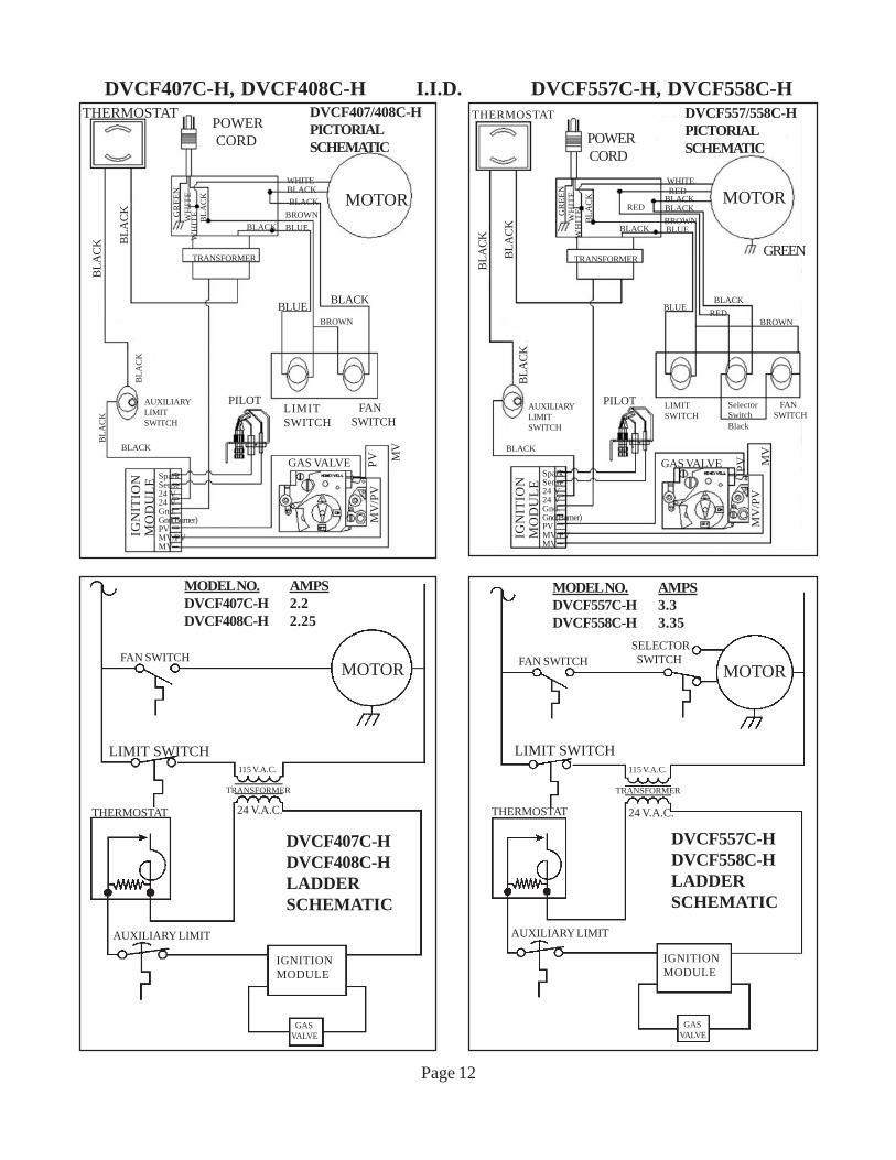
KDVCF407/408C-HPICTORIALSCHEMATIC
IGN
ITIO
NM
OD
UL
E
BL
AC
K
BL
AC
K
BROWN
MV
/PV
MV
PV
BLACK
BLUE
THERMOSTAT
POWER CORD
GR
EE
NW
HIT
EW
HIT
EB
LA
CK
BROWNBLACK
WHITE
BLACK MOTOR
GREEN
BLACK
RED
RED
TRANSFORMER
LIMITSWITCH
FANSWITCH
SelectorSwitchBlack
BL
AC
K
BL
AC
KB
LA
CK
AUXILIARYLIMITSWITCH
BLACK
PILOT
GAS VALVE
DVCF557/558C-HPICTORIALSCHEMATIC
BLUE
BLUERED
BLACK
BROWN
MV
/PV
MV
PV
IGN
ITIO
NM
OD
UL
E
SparkSense24 V24 VGnd.Gnd(Burner)PVMV/PVMV
CAUTION: Label all wires prior to disconnection when servicing controls. Wiring errors cancause improper and dangerous operation. Verify proper operation after servicing.
TERMINAL BLOCK WIRING DIAGRAM
Power Cord (Green)
Terminal BoardGround (Green)
Motor(Green) Power Cord (White)
Transformer (Black)Motor (Black)
FanSwitch(Black)
LimitSwitch(Blue)
Transformer (Black)Power Cord (Black)
Fan/Limit Switch (Brown)
P/N 91122
DVCF403, 404, 407, 408C-H
MOTOR (White)
MAINTENANCE INSTRUCTION
For proper and safe operation, keep furnace and furnace area clean.At regular intervals turn control valve off, let cool and clean insidecontrol compartment. To clean cabinet, use only a damp cloth.Do not use any kind of solvent or cleaning fluid that could leave aresidue or invisible coating that would burn or give off fumeswhen furnace is turned on.
Have the furnace checked, cleaned, and repaired by a qualifiedservice technician, including the vent system, pilot and burneroperation prior to use each year.
The bearings of the fan motor should be oiled every twelve (12)months with S.A.E. 20 oil. (See Figure 10).
Follow a regular service and maintenance schedule for safe andefficient operation.
Examine the venting system as a routine part of the safetyperformance check on an annual basis.
MANUAL RESET SWITCH
For your safety this furnace is equipped with a manual reset limit switch. In case of failure by the primary limit switch, thisswitch will shut the valve down completely before unsafe temperatures are reached. After a cool down period, switch must bemanually reset. If outages persist, call a qualified service person.
OIL TUBE
FIGURE 10
WARNING: This is a gas-fired appliance. Keep the area clear of gasoline and other flammaable vapors andliquids. All combustible material must be kept clear of this area to avoid fire or explosion.
OPTIONAL SIDE DISCHARGE KITSThis kit must be installed by a qualified installer or service technician.
SIDE DISCHARGE ON CASING
1. Use Optional Kit No. 306SR-A.2. Cut out and remove embossed area on casing side.3. Remove knockout from inner liner.4. Place 1-1/2” boot from kit through opening,
matching flanges of boot to knockout on inner liner.5. Mark screw holes and remove boot.6. Drill holes with a 1/8” drill.7. Attach inner boot with screws provided.8. Place grille into position, drill holes into casing,
and attach with screws provided.
SIDE DISCHARGE (With Extension Boot)NOTE: Maximum boot length is 10 inches.
1. Use Optional Kit No. 30SRB-A.2. Cut opening in drywall as shown in Fig. 9.3. Position plaster ground as shown in Figure 9.
(Optional).4. Cut out and remove embossed section on casing side.5. Remove knockout on inner liner.6. Put heater into position.7. Place inner boot into position, mark and cut boot
flush with wall. Place outer boot into position, markand cut boot flush with wall.
8. Place boot trim into position, slide inner boot throughwall from adjacent room and attach to inner liner.Slide outer boot through wall from adjacent roomand attach to casing side.
9. Place grill in position and secure to wall.
ROUGH-INS FOR SIDE DISCHARGE
Install plaster grounds as shown in Figure 9. NOTE: Whenside discharge Kit No. 30SRB is being used, furnace should beset exactly 4” from side wall.
KIT NO. 306SRSIDE REGISTER - FLUSH
KIT NO. 30SRBSIDE REGISTER W/BOOT
Page 14
PlasterGround
10-3/16”
14-3/8”
SIDEFIGURE 9
14-PEK KIT INSTRUCTIONS(14’ PLUG EXTENSION KIT)
This kit must be installed by a qualified installer or service technician.
FOR NON-RECESSED INSTALLATIONS ONLY
90 DegreeOutsideCorner
3 FT.SECTION
WALL
3 FT.SECTION
BOTTOMSECTION
1
2
3
4
UNITS WITH TERMINAL BOARD
STEP #1. Turn heater off following Section 3 in “Lighting
Instructions” and allow to cool.2. Turn off all electricity to heater.3. Remove top louver assembly, fan shroud and fan
blade.4. Loosen two screws on romex connector.5. Remove junction box cover plate.6. Disconnect three power cord terminals and pull
power cord out of top of heater.7. Insert power cord provided in kit through romex
connector and plug onto terminal board followingwiring diagram found in lighting and operatinginstructions.
8. Tighten two screws on romex connector.9. Replace junction box cover plate.10. Replace fan blade, fan shroud and top louver
foot section (Ref. 2) plastic raceway. Insert powercord and remove blue backing from adhesive stripon raceway and apply to side of heater.
12. Insert power cord into second 3-foot section ofraceway (Ref. 3) and remove blue backing andapply to side of heater, butting up against bottomof other section.
13. Cut 14-inch long bottom section to required length(see chart), insert power cord, remove backingand apply to side of heater.
14. Plug power cord into wall receptacle.15. Light the heater following lighting instructions.
Page 15
LENGTH OF BOTTOMSECTION (REF. 4)
MODEL NO. PLASTIC RACEWAYDVCF40 5-5/16 InchesDVCF55 14 Inches
DIRECT VENT COUNTERFLOW WALL FURNACEMODELS:DVCF403C-H, DVCF404C-HDVCF407C-H, DVCF408C-HDVCF553C-H, DVCF554C-HDVCF557C-H, DVCF558C-H
Prices and specifications subject to changewithout notice. All prices are F.O.B. factory.
Page 16
391g
51
1a
1f
1e
1d
24
1b
362
35
61
50
1811
16
173
52 38
30
87
9 2244
10
6
26
1c
4
19 21 20
ATTN: CONTRACTORS AND SERVICETECHNICIANS, we only sell parts through ourwholesalers, but the prices listed are for yourconvenience. For prompt parts service, contactthe wholesaler from which you purchased yourCozy heater. NOTE: Parts & schematic draw-ings on current models are shown atwww.cozyheaters.com.
APRIL 2013REV. 04/2013
THERMOSTAT23
VENT ASSEMBLY
40 37 4948 47
46
45
USE ONLY FACTORY SUPPLIED PARTS
I.I.D. CONTROL MODULEHONEYWELL
43
Spar
k
Sen
se
24 V
24V
Gnd
.
Gnd
.(Bur
ner)
PV
MV
/PV
MVBURNER ASSEMBLY
DVCF40C-H, DVCF55C-H, SERIES
5514 15
12 25b 28b
28 25
34
58
1313b
415357
56315960
32
33
42
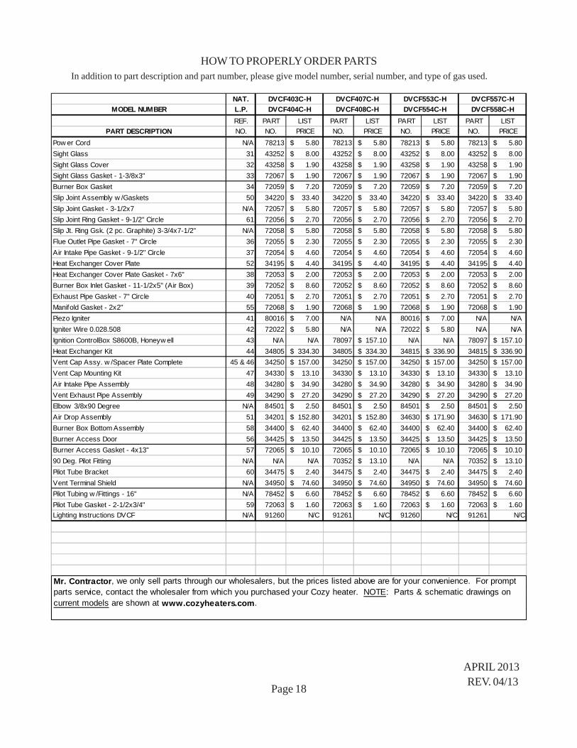
HOW TO PROPERLY ORDER PARTSIn addition to part description and part number, please give model number, serial number, and type of gas used.
APRIL 2013REV. 04/13Page 17
* Requires 2 ** Requires 4
NAT. DVCF407C-H DVCF553C-H DVCF557C-H
MODEL NUMBER L.P. DVCF408C-H DVCF554C-H DVCF558C-H
Mr. Contractor, we only sell parts through our wholesalers, but the prices listed above are for your convenience. For prompt parts service, contact the wholesaler from which you purchased your Cozy heater. NOTE: Parts & schematic drawings on current models are shown at www.cozyheaters.com.
Page 18
In addition to part description and part number, please give model number, serial number, and type of gas used.
Mr. Contractor, we only sell parts through our wholesalers, but the prices listed above are for your convenience. For prompt parts service, contact the wholesaler from which you purchased your Cozy heater. NOTE: Parts & schematic drawings on current models are shown at www.cozyheaters.com.
TROUBLE SHOOTING CHARTFor use by a qualified installer or service technician.
SYMPTOM POSSIBLE CAUSES CORRECTIVE ACTION
Flame too large 1. Defective operator section of valve. 1. Replace valve.2. Burner orifice too large. 2. Check with local gas company for proper orifice
size and replace.3. If installed above 2,000 feet. 3. See orifice chart, page 10.
Yellow burner flame 1. Clogged burner ports. 1. Remove main burner and check for obstructions in throat, ports, and orifices. Clean - but do not enlarge ports or orifices.
2. Obstructions around vent cap. 2. Make sure area around vent cap is clear, be sure vent system is sealed.
Gas Odor 1. Gas leak. 1. See Page 1.
Delayed Ignition 1. Pilot flame too small. 1. Adjust pilot flame.2. Burner ports clogged at pilot. 2. Clean burner ports (do not enlarge).3. Low gas pressure. 3. Check gas supply pressure.4. Pilot decreases in size when main 4. Supply piping is too small. Consult local gas burners come on. company or competent installer.
Failure to ignite 1. Main gas off. 1. Open all manual gas valves.2. Thermostat not set high enough to call 2. Set thermostat to higher temperature. for heat.3. Clogged burner orifice. 3. Clean burner orifice (do not enlarge).4. Thermostat wired wrong or defective. 4. Check wiring, jump across thermostat terminals at
valve, if valve open, re-check wires, replace thermostat.
Burner won’t turn off 1. Defective or damaged thermostat wire, 1. Can be checked by removing wire from valve terminal. or thermostat. If valve goes off, replace wire or thermostat.2. Thermostat location. 2. Follow instructions, check location.3. Defective or sticking valve. 3. Replace valve.4. Excessive gas pressure. 4. Contact utility supplying gas.
Incorrect gas input 1. Gas input not checked. 1. Re-check gas input.2. Clogged orifice. 2. Clean orifice with a smooth wood toothpick,
do not enlarge.
Not enough heat 1. Furnace undersized. 1. This is especially true when a dwelling or room is enlarged. Have the heat loss calculated and compare to furnace output. Your gas company can supply you with this information. If furnace is undersized, replace with correct size unit.
2. Thermostat set too low. 2. Raise temperature setting.3. Incorrect supply pressure. 3. Check supply pressure.
Too much heat 1. Thermostat set too high. 1. Lower temperature setting.2. Combination control valve stuck open. 2. Replace combination control valve.
Pilot and main burner 1. Weak thermocouple. 1. Check millivoltage and replace if low. go out during normal 2. Input too high. 2. Check input rate. operation 3. Cover around pilot lighter hole not 3. Tighten wing nuts securing cover and sight glass.
air tight. Check and replace gasket if needed.4. Vent tubes not properly installed or 4. Follow instructions. Check both exhaust and air sealed. intake tubes, and vent cap. Be sure all gaskets are
in place and properly sealed. Use only tubes and vent cap supplied. Do not alter vent tubes or cap.
Page 19
TROUBLE SHOOTING CHART - ContinuedFor use by a qualified installer or service technician.
SYMPTOM POSSIBLE CAUSES CORRECTIVE ACTION Burner won’t turn on 1. Gas valve not turned on. 1. Turn gas valve to “on” position.
2. No voltage to valve. 2. Check for 24 Volts to valve from transformer.3. Defective thermostat. 3. Check wall thermostat.4. No 115 V. Line voltage. 4. Provide line voltage.5. Gas valve defective. 5. Replace gas valve.6. Manual reset switch not engaged. 6. Depress red button on switch.
(STANDING PILOT) 1. Air in line. 1. Bleed line.2. Defective thermocouple 2. Replace thermocouple.
Pilot won’t light, or 3. Pilot flame too low. 3. Adjust pilot flame. stay lit 4. Manual reset switch not engaged. 4. Depress red button on switch.
Pilot won’t light 2. Sparker won’t light pilot. 2. {a} Pilot flame too small. {b} Turn valve to “on” position. {c} Check for pilot restriction.
3. Manual reset switch not engaged. 3. Depress red button on switch.
SERVICE RECORD SERVICE RECORD
Page 20
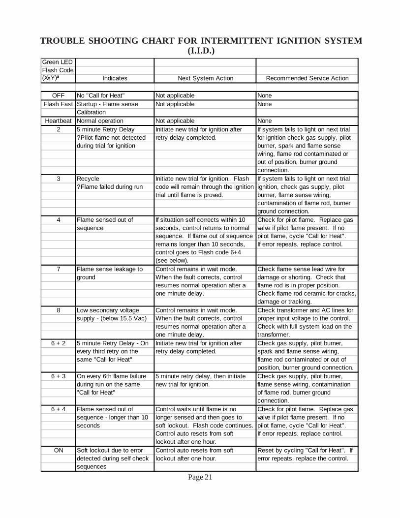
TROUBLE SHOOTING CHART FOR INTERMITTENT IGNITION SYSTEM(I.I.D.) - SEE “PAGE 21”
Page 21
Green LEDFlash Code(XxY)ª Indicates Next System Action Recommended Service Action
OFF No "Call for Heat" Not applicable NoneFlash Fast Startup - Flame sense Not applicable None
CalibrationHeartbeat Normal operation Not applicable None
2 5 minute Retry Delay Initiate new trial for ignition after If system fails to light on next trial? Pilot flame not detected retry delay completed. for ignition check gas supply, pilotduring trial for ignition burner, spark and flame sense
wiring, flame rod contaminated orout of position, burner ground connection.
3 Recycle Initiate new trial for ignition. Flash If system fails to light on next trial? Flame failed during run code will remain through the ignition ignition, check gas supply, pilot
trial until flame is proved. burner, flame sense wiring, contamination of flame rod, burner ground connection.
4 Flame sensed out of If situation self corrects within 10 Check for pilot flame. Replace gassequence seconds, control returns to normal valve if pilot flame present. If no
sequence. If flame out of sequence pilot flame, cycle "Call for Heat".remains longer than 10 seconds, If error repeats, replace control.control goes to Flash code 6+4(see below).
7 Flame sense leakage to Control remains in wait mode. Check flame sense lead wire forground When the fault corrects, control damage or shorting. Check that
resumes normal operation after a flame rod is in proper position.one minute delay. Check flame rod ceramic for cracks,
damage or tracking.8 Low secondary voltage Control remains in wait mode. Check transformer and AC lines for
supply - (below 15.5 Vac) When the fault corrects, control proper input voltage to the control.resumes normal operation after a Check with full system load on theone minute delay. transformer.
6 + 2 5 minute Retry Delay - On Initiate new trial for ignition after Check gas supply, pilot burner, every third retry on the retry delay completed. spark and flame sense wiring, same "Call for Heat" flame rod contaminated or out of
position, burner ground connection.6 + 3 On every 6th flame failure 5 minute retry delay, then initiate Check gas supply, pilot burner,
during run on the same new trial for ignition. flame sense wiring, contamination "Call for Heat" of flame rod, burner ground
connection.6 + 4 Flame sensed out of Control waits until flame is no Check for pilot flame. Replace gas
sequence - longer than 10 longer sensed and then goes to valve if pilot flame present. If no seconds soft lockout. Flash code continues. pilot flame, cycle "Call for Heat".
Control auto resets from soft If error repeats, replace control.lockout after one hour.
ON Soft lockout due to error Control auto resets from soft Reset by cycling "Call for Heat". If detected during self check lockout after one hour. error repeats, replace the control.sequences
TROUBLE SHOOTING CHART FOR INTERMITTENT IGNITION SYSTEM(I.I.D.)
LIMITED WARRANTYThe Louisville Tin & Stove Co. warrants to
the original user the accompanying product for the period specified herein, provided said product is installed, operated, maintained, serviced, and used according to the instructions and specifications accompanying the product. AS OUTLINED IN OUR INSTRUCTIONS, ANY WARRANTY CONSIDERATIONS ARE CONTINGENT ON INSTALLATION BY A QUALIFIED INSTALLER (CONTRACTOR). SELF-INSTALLATION IS PROHIBITED AND WILL INVALIDATE YOUR WARRANTY. If within a period of one year from the date of installation of the product, any part supplied by the manufacturer proves to be defective due to workmanship or material, it will replace such part, provided parts have not been subjected to misuse, alteration, neglect, or accidents. The term of the warranty for the heat exchanger and burners is covered in Table A below. Any claim not made within ten (10) days after the expiration of the warranty period shall be deemed waived by the user. The manufacturer shall have no liability or be required to perform any obligation under this warranty unless, when requested, the user returns, at the user’s expense, the component or product claimed defective, to the manufacturer for inspection, to enable the manufacturer to determine if the claimed defect is covered by this warranty. No charges for freight, labor or other expenses incurred in the repair, removal, or replacement of any product or component claimed to be defective, will be paid by the manufacturer to the user, and the manufacturer will not be liable for any expenses incurred, by the user, in remedying any defect in the product. Service under this warranty is the responsibility of the installer. In the event service under this warranty is needed, the user of the product
shall request such service directly from the installer. If the user is unable to locate the installer, the user should write directly to the manufacturer, and the name of an alternative service source will be supplied. The product safety registration card (packed inside the appliance) must be completed and returned to the factory. THIS WARRANTY IS EXPRESSLY IN LIEU OF ANY OTHER WARRANTIES, EXPRESS OR IMPLIED (WHETHER WRITTEN OR ORAL). ANY IMPLIED WARRANTY OF MERCHANTABILITY OR OF FITNESS FOR A PARTICULAR PURPOSE IS EXPRESSLY LIMITED TO THE DURATION OF THE MANUFACTURER’S EXPRESS, WRITTEN WARRANTY. UNDER NO CIRCUMSTANCES SHALL THE MANUFACTURER BE LIABLE FOR ANY SPECIAL, INDIRECT OR CONSEQUENTIAL DAMAGES OR EXPENSES ARISING DIRECTLY OR INDIRECTLY FROM ANY COMPONENT OR FROM THE USE THEREOF. THE REMEDIES SET FORTH HEREIN SHALL BE THE EXCLUSIVE REMEDIES AVAILABLE TO THE USER AND ARE IN LIEU OF ALL OTHER REMEDIES. SOME STATES DO NOT ALLOW LIMITATIONS ON HOW LONG AN IMPLIED WARRANTY LASTS, SO THE ABOVE LIMITATIONS MAY NOT APPLY TO YOU. SOME STATES DO NOT ALLOW THE EXCLUSION OR LIMITATION OF INCIDENTAL OR CONSEQUENTIAL DAMAGES, SO THE ABOVE LIMITATIONS OR EXCLUSIONS MAY NOT APPLY TO YOU. THIS WARRANTY GIVES YOU SPECIFIC LEGAL RIGHTS, AND YOU MAY ALSO HAVE OTHER RIGHTS, WHICH VARY, FROM STATE TO STATE.
LOUISVILLE TIN & STOVE COMPANY 737 S. 13TH STREET - LOUISVILLE, KY. 40210
TABLE A Warranty Period Product Heat Exchanger/Tubes Burners Cozy Gas Fired Floor Furnace 10 Years 10 Years Cozy Gas Fired Wall Furnace 10 Years 10 Years Cozy Gas Fired Vented Console Heater 10 Years 10 Years Cozy Gas Fired Direct Vent Heater 10 Years 10 Years Cozy Gas Fired Counterflow Furnace 10 Years 10 Years Cozy Gas Fired Counterflow Direct Vent Furnace 10 Years 10 Years Cozy Gas Fired Mobile Home Direct Vent Furnace 10 Years 10 Years Cozy Gas Fired Hi-Efficient Direct Vent Wall Furnace 10 Years 10 Years Cozy Gas Fired Direct Vent Baseboard Heater 10 Years 10 Years Cozy Fan-Type, Direct Vent Through-The-Wall Gas Heater 10 Years 10 Years Cozy Blue Flame Vent Free Heater N/A 10 Years Cozy Infra-Red Vent Free Heater N/A N/A