Hung-Ta Chien,1 Hui-Ting Tang,1 Chao-Hsien Kuo,2 Chii-Chang Chen,1 and Zhen Ye2,*1Institute of Optical Science, National Central University, Chungli, Taiwan
2Wave Phenomena Laboratory, Department of Physics, National Central University, Chungli 32054, Taiwan(Received 21 December 2003; revised manuscript received 26 March 2004; published 8 September 2004)
Using the FDTD method, we investigate the electromagnetic propagation in two-dimensional photoniccrystals, formed by parallel air cylinders in a dielectric medium. The corresponding frequency band structureis computed using the standard plane-wave expansion method. It is shown that within partial band gaps, wavestend to bend away from the forbidden directions. This phenomenon perhaps need not be explained in terms ofnegative refraction or “superlensing” behavior, contrast to what has been conjectured. Rather it is related to thecollimation property of photonic crystals.
Ever since the suggestion that a perfect lens can be real-ized by left handed materials(LHMs) or negative refractionindex materials(NRIMs),1 a material first conceptually intro-duced by Veselago many years ago,2 the research on super-lenses and LHMs has been skyrocketing in the midst ofmuch debate. A great body of literature has been and contin-ues to be generated. The research ranges from finding char-acteristics of LHMs, negative refraction behavior(NRB), tofabricating composite materials which may reveal as LHMs.All this can be referred to in Ref. 4 In spite of some seriousdebates,5 the common consensus seems to agree that thenegative refraction, equivalently the LHMs, has beenconfirmed.6
Up to date, there are mainly three perspectives regardingnegative refraction; this situation has caused some confusionto a certain degree. First, the concept of negative refractionwas initiated and specified with respect to LHMs, for whichthe energy flowing direction is opposite to the phase velocity,as originally proposed by Veselago.2 For composite materi-als, the individual components may be positively refractive.But when put together, the materials as a whole may behaveeffectivelyas a negative refracting medium, and a negativerefraction index could be defined.7 The second is to observethe refraction into the same side as the incident wave,8,9 andattempt to link to negative refraction. This second aspect canbe easily observed when waves pass across the boundarybetween an isotropic and an anisotropic medium, and can bewell explained by the anisotropy of the medium.9 This ob-servation is in fact irrelevant to the negative refraction in theoriginal context of negative refraction. The third aspect is toshow negative refraction without employing an effective re-fractive index.
In a recent communication, Luoet al.3 described an all-angle negative refraction by photonic crystals, without aneffective negative refraction index. By simulation, the au-thors demonstrated a frequency range in which one obtains asingle negative-refracted beam for all incident angles. It wasshown that a slab of photonic crystal can focus a point sourceon one side of the slab intoa real point image on the otherside even for the case a parallel sided slab of materials, thatis, the flat slab imaging. This phenomenon has been con-nected to the superlensing phenomenon discussed byVeselago2 and Pendry1 for a slab of LHMs. The simulation in
Ref. 3 has stimulated a number of further experimental andtheoretical attempts in verifying the negative refraction be-havior of photonic crystals.10
Three questions, however, may concern with the super-lensing phenomenon and the negative refraction discussed inRef. 3. The first question is: if a refraction does not need aneffective negative refraction index, but is still classified asnegative, then this type of refraction will not be related to thenegative refraction in its original meaning. As such, the su-perlensing or perfect lensing phenomenon discussed in Ref.3 is doubtful, since the evanescent waves may not be ampli-fied as expected for superlensing.1 The second question iswhether the “superlensing” or the flat slab imaging can beexplained by other mechanisms. The third question iswhether there is indeed negative refraction as suggested.3
The second question has been answered in Refs. 11 and 12.As shown in Ref. 11, the imaging by a photonic crystal slabcan be caused by partial band-gap effects or anisotropic scat-tering. With regard to the third question, we think that theanswer from Ref. 3 is not conclusive. In this Brief Report,we wish to shed some light to the third question, in the hopethat more discussions can be stimulated.
We will consider exactly the same two-dimensional pho-tonic crystal systems as in Ref. 3. Specifically, we consider asquare lattice of identical air cylinders(holes) in a dielectricmedium with dielectric constante=12. The lattice constant isdenoted bya and the hole radiusr =0.35a. In accordancewith Ref. 3, we consider TE modes, that is, the magneticfield is kept parallel to the axis of the air cylinders.
In order to compute the electromagnetic propagationthrough the arrays of air cylinders, we have performed finite-difference time-domain(FDTD) simulations with perfectlymatched layer(PML) boundary conditions. In the simulation,we scale all lengths by the lattice constant and the angularfrequency by 2pc/a to make the system dimensionless.
First, we would like to duplicate the flat slab imagingobserved in Ref. 3. The band structure of the system is plot-ted in Fig. 1(a), in full agreement with the result in Fig. 3 ofRef. 3. We see that there is a partial band gap between about0.18 and 0.25, within which the waves are prohibited frompropagation along theGX (Ref. 10) direction.
By the FDTD method, we have simulated the wave propa-gation across a flat(11)-oriented slab of lattice of air cylin-
ders. Hereafter, the slabs of photonic crystals are all placedin air, in line with the Ref. 3. The geometric parameters aregiven in the figure caption. Figure 1(b) shows a snapshot ofthe magnetic field for a point source transmitting thecontinuous-wave of frequency 0.192, which lies within theregime of so called all-angle negative refraction(AANR).3
Note that we have also done with frequency 0.195 as in Ref.3, the results are qualitatively the same. Here we indeed ob-
FIG. 1. (Color) (a) The band structure of a square lattice of airholes embedded in the dielectric mediume=12. The lattice constantis a and the radius of the cylinders is 0.35a. GM andGX denote the[11] and[10] directions, respectively,(b) the magnetic fieldHz of apoint source and its image across a photonic crystal slab calledsuperlens in Luoet al. (Ref. 3). The slab measures 11.31331.11,and the frequency is 0.192.(c) the conceptual layout of a superlens-ing phenomenon, adapted from Veselago(Ref. 2) and Pendry(Ref.1); (d) the illustration of negative refraction which would be ex-pected for a plane wave across a flat slab, by analogy with theright-hand side of Fig. 2 in Ref. 3.
FIG. 2. (Color) The intensity image of the magnetic fields acrossa flat photonic crystal slab made of air holes in dielectrice=12. Theprinciple directions of the crystal are shown in the figure, as[11]and [10]. A Gaussian beam is incident to the slab with variousincident angles in degrees with respect to the[11] direction: (a) 0;(b) 22.5; (c) 45; and(d) 67.5. The slab measures as 49.5392 interms of lattice constant. For clarity, the air holes are not shown inthe figure.
FIG. 3. (Color) The intensity image of the magnetic fields acrossa flat photonic crystal slab. The principle directions of the crystalare shown in the figure, as[11] and[10]. The[11] direction is tiltedtowards the left by an angle of 22.5° with reference to the normaldirection of the slab surface. A Gaussian beam is incident to the slabwith various incident angles in degrees with respect to the normaldirection of the slab surface:(a) 0; (b) 22.5; (c) 45; and(d) −22.5.The slab measures as 49.5392 in terms of lattice constant.
FIG. 4. (Color) The intensity image of the magnetic fields acrosstwo flat photonic crystal slabs. The principle directions of the crys-tal are shown in the figure, as[11] and[10]. The two slabs measurein terms of lattice constant as(a) 70392; (b) 49.53120. A Gauss-ian beam is incident to the slab with the incident angle of 22.5° withrespect to the normal direction of the slab surface.
FIG. 5. (Color) The intensity image of the magnetic fields acrossa flat photonic crystal slabs. The principle directions of the crystalare shown in the figure, as[11] and [10]. The slab measures interms of lattice constant as 993184. A Gaussian beam is incident tothe slab with the incident angle of 22.5° with respect to the normaldirection of the slab surface. The beam width amounts to 70 latticeconstant.
BRIEF REPORTS PHYSICAL REVIEW B70, 113101(2004)
113101-2
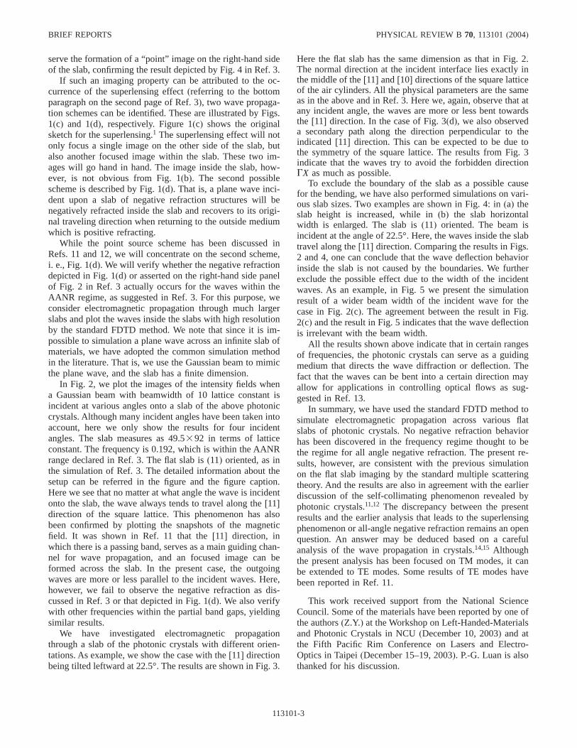
serve the formation of a “point” image on the right-hand sideof the slab, confirming the result depicted by Fig. 4 in Ref. 3.
If such an imaging property can be attributed to the oc-currence of the superlensing effect(referring to the bottomparagraph on the second page of Ref. 3), two wave propaga-tion schemes can be identified. These are illustrated by Figs.1(c) and 1(d), respectively. Figure 1(c) shows the originalsketch for the superlensing.1 The superlensing effect will notonly focus a single image on the other side of the slab, butalso another focused image within the slab. These two im-ages will go hand in hand. The image inside the slab, how-ever, is not obvious from Fig. 1(b). The second possiblescheme is described by Fig. 1(d). That is, a plane wave inci-dent upon a slab of negative refraction structures will benegatively refracted inside the slab and recovers to its origi-nal traveling direction when returning to the outside mediumwhich is positive refracting.
While the point source scheme has been discussed inRefs. 11 and 12, we will concentrate on the second scheme,i. e., Fig. 1(d). We will verify whether the negative refractiondepicted in Fig. 1(d) or asserted on the right-hand side panelof Fig. 2 in Ref. 3 actually occurs for the waves within theAANR regime, as suggested in Ref. 3. For this purpose, weconsider electromagnetic propagation through much largerslabs and plot the waves inside the slabs with high resolutionby the standard FDTD method. We note that since it is im-possible to simulation a plane wave across an infinite slab ofmaterials, we have adopted the common simulation methodin the literature. That is, we use the Gaussian beam to mimicthe plane wave, and the slab has a finite dimension.
In Fig. 2, we plot the images of the intensity fields whena Gaussian beam with beamwidth of 10 lattice constant isincident at various angles onto a slab of the above photoniccrystals. Although many incident angles have been taken intoaccount, here we only show the results for four incidentangles. The slab measures as 49.5392 in terms of latticeconstant. The frequency is 0.192, which is within the AANRrange declared in Ref. 3. The flat slab is(11) oriented, as inthe simulation of Ref. 3. The detailed information about thesetup can be referred in the figure and the figure caption.Here we see that no matter at what angle the wave is incidentonto the slab, the wave always tends to travel along the[11]direction of the square lattice. This phenomenon has alsobeen confirmed by plotting the snapshots of the magneticfield. It was shown in Ref. 11 that the[11] direction, inwhich there is a passing band, serves as a main guiding chan-nel for wave propagation, and an focused image can beformed across the slab. In the present case, the outgoingwaves are more or less parallel to the incident waves. Here,however, we fail to observe the negative refraction as dis-cussed in Ref. 3 or that depicted in Fig. 1(d). We also verifywith other frequencies within the partial band gaps, yieldingsimilar results.
We have investigated electromagnetic propagationthrough a slab of the photonic crystals with different orien-tations. As example, we show the case with the[11] directionbeing tilted leftward at 22.5°. The results are shown in Fig. 3.
Here the flat slab has the same dimension as that in Fig. 2.The normal direction at the incident interface lies exactly inthe middle of the[11] and[10] directions of the square latticeof the air cylinders. All the physical parameters are the sameas in the above and in Ref. 3. Here we, again, observe that atany incident angle, the waves are more or less bent towardsthe [11] direction. In the case of Fig. 3(d), we also observeda secondary path along the direction perpendicular to theindicated[11] direction. This can be expected to be due tothe symmetry of the square lattice. The results from Fig. 3indicate that the waves try to avoid the forbidden directionGX as much as possible.
To exclude the boundary of the slab as a possible causefor the bending, we have also performed simulations on vari-ous slab sizes. Two examples are shown in Fig. 4: in(a) theslab height is increased, while in(b) the slab horizontalwidth is enlarged. The slab is(11) oriented. The beam isincident at the angle of 22.5°. Here, the waves inside the slabtravel along the[11] direction. Comparing the results in Figs.2 and 4, one can conclude that the wave deflection behaviorinside the slab is not caused by the boundaries. We furtherexclude the possible effect due to the width of the incidentwaves. As an example, in Fig. 5 we present the simulationresult of a wider beam width of the incident wave for thecase in Fig. 2(c). The agreement between the result in Fig.2(c) and the result in Fig. 5 indicates that the wave deflectionis irrelevant with the beam width.
All the results shown above indicate that in certain rangesof frequencies, the photonic crystals can serve as a guidingmedium that directs the wave diffraction or deflection. Thefact that the waves can be bent into a certain direction mayallow for applications in controlling optical flows as sug-gested in Ref. 13.
In summary, we have used the standard FDTD method tosimulate electromagnetic propagation across various flatslabs of photonic crystals. No negative refraction behaviorhas been discovered in the frequency regime thought to bethe regime for all angle negative refraction. The present re-sults, however, are consistent with the previous simulationon the flat slab imaging by the standard multiple scatteringtheory. And the results are also in agreement with the earlierdiscussion of the self-collimating phenomenon revealed byphotonic crystals.11,12 The discrepancy between the presentresults and the earlier analysis that leads to the superlensingphenomenon or all-angle negative refraction remains an openquestion. An answer may be deduced based on a carefulanalysis of the wave propagation in crystals.14,15 Althoughthe present analysis has been focused on TM modes, it canbe extended to TE modes. Some results of TE modes havebeen reported in Ref. 11.
This work received support from the National ScienceCouncil. Some of the materials have been reported by one ofthe authors(Z.Y.) at the Workshop on Left-Handed-Materialsand Photonic Crystals in NCU(December 10, 2003) and atthe Fifth Pacific Rim Conference on Lasers and Electro-Optics in Taipei(December 15–19, 2003). P.-G. Luan is alsothanked for his discussion.
BRIEF REPORTS PHYSICAL REVIEW B70, 113101(2004)
113101-3
*Corresponding author; electronic address: [email protected]. B. Pendry, Phys. Rev. Lett.85, 3966(2000).2V. G. Veselago, Sov. Phys. Usp.10, 509 (1968).3C. Luo, S. G. Johnson, J. D. Joannopoulos, and J. B. Pendry,
Phys. Rev. B65, 201104(R) (2002).4Refer to the news reported in physicsweb.org and
www.photonics.com5P. M. Valanju, R. M. Walser, and A. P. Valanju, Phys. Rev. Lett.
88, 187401(2002); N. Garcia and M. Nieto-Vesperinas, Opt.Lett. 27, 885 (2002).
6J. Pendry, Nature(London) 423, 22 (2003).7R. A. Shelby, D. R. Smith, and S. Schultz, Science292, 77
(2001).
8http://physicsweb.org/article/news/7/10/10.9H.-F. Yau, J.-P. Liu, B.-W. Ke, C.-H. Kuo, and Z. Ye, cond-mat/
0312125, Phys. Rev. B(to be published).10http://www.nupr.neu.edu/11-03/nature.html11C.-H. Kuo and Z. Ye, cond-mat/0310423(unpublished); cond-
mat/0312288(unpublished).12Z.-Y. Li and L.-L. Lin, Phys. Rev. B68, 245110(2003).13L.-S. Chen, C.-H. Kuo, and Z. Ye, Phys. Rev. E69, 066612
(2004).14A. Yariv and P. Yeh,Optical Waves in Crystals(John Wiley,
Taipei, 1984).15Z. Ye (unpublished); C.-H. Kuo and Z. Ye, cond-mat/0405008