30
Directional Drilling with Percussion Tools Jeff White Atlas Copco CMT PIOGA - Seven Springs, PA July 23, 2014

Directional Drilling with Percussion Tools
Jeff White Atlas Copco CMT
PIOGA - Seven Springs, PA July 23, 2014

Discussion
Project scope
Necessary equipment
Testing
Results

Project scope
Learn more about the directional market and equipment.
- Ellen Montgomery, Crescent Directional - Glen Wright, NOV
Identify and quantify existing applicable Atlas Copco tooling.
- Jet subs, hammer equipment modifications, Hydrocyclones
Partner with those folks “in the know”.
- Initial testing done with EQT during Berea drilling program (6” work)
Testing to acquire empirical data.
- Advent of Marcellus and Utica offered more opportunity
Detail / design necessary equipment for success.
Share results.

Example of anti-collision nudge

Concerns for Horizontal application
Drilling in hydrocarbon bearing zone.
Hazard mitigation for fire prevention will be necessary.
Nitrogen should be used.
- Physical properties of nitrogen and air are very similar, but with nitrogen
separation there is a volumetric loss.
Creating a “Wet” environment by injecting fluids may be sufficient
Requires specialty equipment for prevention of productivity losses

Advantages:
What we have learned:
Control motor speed by addressing flow/pressure needs
Adjust air volumes consumed by motor / hammer
Extended bit life (flow)
Reduce motor vibration (speed)
Increase annular velocity in stages
- Enhanced hole cleaning
Injected Fluids (Hydrocyclone / Berea)
Adjustable Orifice plates
- Pressure/flow regulated
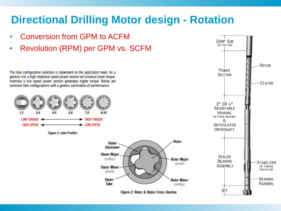
Directional Drilling Motor design - Rotation • Conversion from GPM to ACFM • Revolution (RPM) per GPM vs. SCFM

8
Hammers/bits: Proper Rotation Speed Rotation Theory
(Diameter of bit) x pi(3.14) = circumference of the bit
(Circumference of bit)/(diameter of button) = Number of times bit should be moved per revolution
(Impact frequency (blows per minute) of hammer)/(number of times bit should be moved) = Correct rpm
So, if we plug in the numbers and make the calculations:
17119 1400
900 950
537.212328.27433
31.83099Correct RPM:
Diameter of buttons (mm): TD90Impact frequency: QL120
The purpose of rotation is to turn the drill bit to a suitable point for the next blow. Theoretically, in the case of button bits, the bit should be rotated at each impact of the hammer a distance equal to the diameter of the gauge buttons. This allows the buttons to impact virgin material on each impact. If rotation is too slow, the buttons re-crush material already impacted; if rotation is too fast, the button “jumps over” virgin material and causes inefficient drilling, and potential overheating of bit and excessive wear.
So, to arrive at the optimum rotation of the bit, we use the following formula:
Diameter of bit(mm): Impact frequency (to be used if you are not sure of
Circumference of bit:# of blows per revolution
With the jet subs, we are able to control motor speed
and resulting hammer bit rotation speed.

Weight / Rotation Animation TCB Cutting Mechanism (Crushing)
Learned : Less weight on bit required for percussion tools.
- May offer better steering control due to a lesser reactive torque.

PDC cutting mechanics Weight and rotation provides shearing

QL120,QLX100,TD90,QL60 Modified Hammer Tool
Off bottom flow control
- As the hammer is restricting flow while on bottom, when the pipe section is drilled down, and the is hammer picked up off bottom to make a connection, the drill string air volume is evacuated immediately through the motor.
- The tool’s Blow Down Sequencing has been modified to ensure the hammer will allow very close to the same flow off bottom as when cycling. This controls rotation speed while on and off bottom of the directional motor (PDM)
- This feature of these tools used prevents “whipping” of the BHA caused by sudden increased rotation of the motor due to the introduction of high flow rates of air while off bottom.

Quantum Leap DTH Air cycle Blowing and flushing mode
Simple change in metering ports allows for
controlling off-bottom rotation speed..
Live/compressed air
Exhaust/expanded air
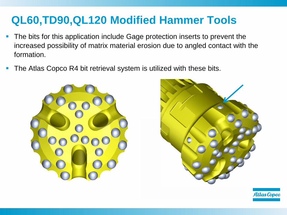
QL60,TD90,QL120 Modified Hammer Tools The bits for this application include Gage protection inserts to prevent the
increased possibility of matrix material erosion due to angled contact with the formation.
The Atlas Copco R4 bit retrieval system is utilized with these bits.

Specialized bits for 6” work

15
R4 Retrieval Animation

16
Bits with Drive pins
Austenite & Untempered Martensite Crystalline
Atlas Copco’s patented drive pin system reduces possibility of bit failures. No metal
on metal contact.

Integral Blade Stabilizer/Jet Sub
• EQT Drilling Paper SPE 135308 • IADC/SPE Drilling Paper 99162

In-Line String Jet Subs

Annular Velocity Throttling
1200 CFM 11,904 fpm
+ 750 / 1950 CFM 18,570 fpm
+ 500 / 2450 CFM 23,330 fpm

Inducer – Spins water/air mixture. Water is denser and is forced to the outside of the backhead bore.
Separator – forces water to expulsion chamber.
Expulsion Ports – Channels water to annular area. (Well bore)

Hydrocyclone Animation


23 23 23
The EDGE drill monitor
What is it? – An “always on” electronic Hammer Hand
specifically designed for percussive drilling
How does it work? – Uses a sensor mounted on the rotary head
that can detect and translate hammer percussion or vibration signals into an easy to read “real time” display
Hammer & Bit
Vibrations signals up
the drill pipe
24 24
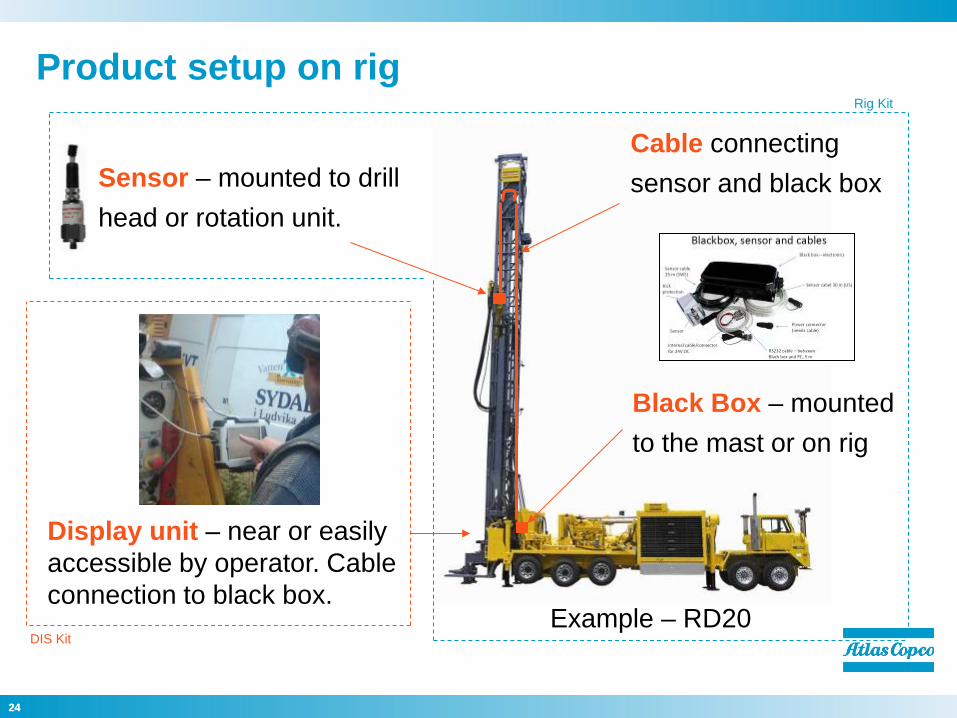
Product setup on rig
Sensor – mounted to drill head or rotation unit.
Black Box – mounted to the mast or on rig
Cable connecting sensor and black box
Display unit – near or easily accessible by operator. Cable connection to black box.
Example – RD20
Rig Kit
DIS Kit

25 25
Driller’s display
Detailed Display
Basic Display
F - Piston frequency in Hz
S - Spread of piston frequency Indicates consistency, smaller better
A1 - Piston impact energy Not a true measure but indicator of
energy transmission. The value also is an indicator of the quality of the signal
A2 & A3 resonance frequency Indicator of reflected or wasted energy
S – note, ideally the spread would be “0” if the frequency stayed constant. When the rock consistency changes so does goes the timing of the piston and efficiency.
A2 & A3 represent reflected energy that is basically wasted. In monitoring the display the driller wants to keep these two numbers as low as possible while maximizing A1.
A1 – primary indicator The relationship between A1, A2, and A3 define a signature of any given situation.
Primary objective is to maximize A1 for given conditions.
S

26
Driller’s display
Detailed Display
Basic Display
F - Piston frequency in Hz
S - Spread of piston frequency Indicates consistency, smaller better
A1 - Piston impact energy Not a true measure but indicator of
energy transmission. The value also is an indicator of the quality of the signal
A2 & A3 resonance frequency Indicator of reflected or wasted energy
S – note, ideally the spread would be “0” if the frequency stayed constant. When the rock consistency changes so does the timing of the piston and efficiency.
A2 & A3 represent reflected energy that is basically wasted. In monitoring the display the driller wants to keep these two numbers as low as possible while maximizing A1.
A1 – primary indicator The relationship between A1, A2, and A3 define a signature of any given situation.
Primary objective is to maximize A1 for given conditions.
S
PASON VIEW

27 27 27
Example: 3900 Foot pipe Change
0 100 200 300 400 500
0
500
1k
1.5k
2k
2.5k
3k
3.5k
4k
4.5k
5k[RPM]
Drill Stops
Drill Starts Againwith new Rod Hammer Speed
Stabilizes
Note: Piston frequency shown in blows per Minute
Faster and better pipe change
Normally Undetected!
Problem for 2 mins.
Frequency
Seconds Potential improvement using EDGE Better hammer control and shorter time to full speed for each drill pipe
change!

Conclusions:
We have achieved significantly greater penetration rates utilizing the system over conventional tooling..
Significantly less vibration down hole due to flow control and optimizing hammer / motor air volume requirements.
MWD / EM equipment damage has been eliminated. (vibration reduction)
Reduced bit wash/enhanced bit life/performance (less air exhausted at the bit)
Edge Drill Monitor System enhances performance
Technology should apply to horizontal drilling
Achieved with a very simple and reliable drilling system!

Committed to sustainable productivity.


