Directional Liquid Spreading over Chemically Defined RadialWettability GradientsOlesya Bliznyuk,† James R.T. Seddon,‡ Vasilisa Veligura,† E. Stefan Kooij,*,† Harold J. W. Zandvliet,†
and Bene Poelsema†
†Physics of Interfaces and Nanomaterials and ‡Physics of Fluids, MESA+ Institute for Nanotechnology, University of Twente,Enschede, The Netherlands
ABSTRACT: We investigate the motion of liquid droplets onchemically defined radial wettability gradients. The patternsconsist of hydrophobic fluorinated self-assembled monolayers(SAMs) on oxidized silicon substrates. The design comprises acentral hydrophobic circle of unpatterned SAMs surrounded byannular regions of radially oriented stripes of alternatingwettability, i.e., hydrophilic and hydrophobic. Variation in therelative width of the stripes allows control over the macroscopicwettability. When a droplet is deposited in the middle, it willstart to move over to the radially defined wettability gradient,away from the center because of the increasing relative surfacearea of hydrophilic matter for larger radii in the pattern. The focus of this article is on a qualitative description of thecharacteristic motion on such types of anisotropic patterns. The influence of design parameters such as pattern dimensions,steepness of the gradient, and connection between different areas on the behavior of the liquid are analyzed and discussed interms of advancing and receding contact lines, contact angles, spatial extent, and overall velocity of the motion.
Ink jet printers encompass a popular choice both for householdpurposes as well as for many different industrial applications.For domestic use, the low price is a major advantage, whereasfor industrial purposes, the versatility of the technology is ofprime importance, enabling printing of a wide range ofmaterials on various substrates.1,2 Most recently, thepossibilities of printing were even extended to three-dimen-sional objects.3,4 The application areas for ink jet technologyinclude displays,5,6 the chemical industry,7,8 electroniccomponents,9−12 and a large emerging field comprising thelife sciences.13,14 For all these applications, high speed andultimate printing quality are required. This in turn has resultedin a lot of research activities in this area. Companies andresearch institutes developing the technology are faced with thechallenge to further miniaturize and increase efficiency of theink jet print heads.The developments in silicon-based micro electro mechanical
systems (MEMS) are presently also being applied to the ink jettechnology. For instance, in 2008 27% of all inkjet printheadswere fabricated using MEMS technologies. Despite thesubstantial investments initially required, many printingcompanies incorporate MEMS into their products for mass-production, since this technology enables achieving submi-crometer resolution with high reliability, which is a must forlarge scale applications.15 However, miniaturization of devicesposes new challenges dictated by the fact that considerably
more features have to be reproduced on markedly smallersurface areas.16
The way the droplets are created in a typical print head givesrise to small volumes of ink overflowing from the nozzles andultimately wetting the nozzle plate.2,17 Both metal and siliconnozzle plates are lyophilic for low surface tension inks,inhibiting complete removal of the residual ink by mechanicalwiping. Accumulation of ink near the nozzle interferes withjetting of droplets and may lead to the interruption of jetting alltogether by blocking the nozzle.18−20 This in turns leads tounreliable jetting behavior and is consequently detrimental forthe print quality. Moreover, silicon nozzle plates asmanufactured using MEMS technology exhibit wettabilitycharacteristics, which are strongly affected by ambientconditions such as temperature and humidity. Additionally,the silicon surface is easily contaminated therewith creatingpinning sites which interfere with ink removal procedures.A smart way to avoid undesired ink accumulation near the
nozzle is to apply an antiwetting coating on the nozzleplate.2,21,22 The surface is hydrophobized using a chemicallyinert agent, which allows easy removal of ink and reducescontamination. Presently, such an antiwetting coating isprimarily applied as a single chemical species homogeneouslydeposited over the entire nozzle plate. However, it may be
Received: May 17, 2012Accepted: July 27, 2012Published: July 27, 2012
relevant to design patterns of more (typically two) chemicalspecies with different surface energies, which will enablecontrolling ink movement on the nozzle plate, ultimatelyachieving a continuous flow of ink away from the nozzle.Despite the pioneering work on using surface energy gradientsto control liquid motion, for example that of Chaudhury andWhitesides,23 the inspiration to actually apply spatially varyingwetting properties in modern technology to induce actuation ofliquid droplets has only attracted increasing attention over thepast 2 years. Both theoretical and experimental work hasbecome focused on designing, manufacture and character-ization of reliable, robust surfaces with well-defined wettabilitygradients.24−32
More generally, the topic of wetting of patterned surfacescomprises an extensive research field. The behavior of liquiddroplets on anisotropically patterned surface is typicallyreferred to as “directional wetting”. Over the past decade anumber of reviews have been written on the topic.33−36
Anisotropic wetting characteristics give rise to different liquidspreading behavior in orthogonal directions. Such anisotropycan be induced either by morphological patterning, for examplea grooved surface, or by chemical patterning with a specificdirectionality. In the former case, two wetting states oftenreferred to as (i) Cassie−Baxter and (ii) Wenzel states areobserved in which the liquid is elevated on top of surfaceasperities, or penetrates into the crevices, respectively. In thecase of morphologically flat substrates with a spatially varyingsurface energy, the liquid is in all cases in contact with theentire surface.By applying a gradient in the macroscopic wettability, it is in
principle possible to induce liquid motion on such surfaces. Aspatial gradient in surface energy is one way to passively controlthe movement of liquid in a specific direction. Alternatively,one can resort to active actuation using electrowetting,illumination or electrochemical means.33 Recently, the abilityto move liquids over linear wettability gradients, constitutingchemically defined micrometer-sized stripes of alternatingwettability has been demonstrated both experimentally and insimulations.35,37−39 In this article, we present a study of liquidbehavior on radially patterned surfaces. A surface free energygradient induces droplet motion away from the point where itis deposited. We describe the patterns used to define thegradient and briefly indicate how they are made. A globaldescription of the droplet motion is given, followed by a moredetailed treatment of the receding motion. We also discuss theresidual layer, which remains on the hydrophilic SiO2 areas afterthe droplet has receded. The formation of single ridges of liquidas well as bridges covering up to 20 adjacent stripes at regularintervals and their influence on receding motion is presented.Finally, the influence of the radial pattern length on the velocityis discussed.
■ EXPERIMENTAL DETAILSSurface Preparation. The surface patterns of self-assembled
monolayers (SAMs) of 1H,1H,2H,2H-perfluorodecyltrichlorosilane(PFDTS, 97%, ABCR, Germany) on silicon wafers are created usingstandard clean room facilities. First, a positive photoresist is spin-coated on freshly cleaned wafers with a natural oxide film, followed bysoft-baking. Patterns are created via standard optical lithography, afterwhich the exposed photoresist is washed-off. The remainingphotoresist is hard-baked and provides surface protection duringvapor deposition of PFDTS; the silane headgroup binds covalently tothe native silicon oxide, exposing the fluorinated tail to the liquid. Theassembly creates a densely packed layer of molecules with a height in
the order of one nanometer, on which glycerol has a stationary contactangle (CA) θst = 106°. Vapor deposition of PFDTS is done in adegassed chamber that is successively exposed to PFDTS and waterreservoirs to introduce the respective vapors, initiating the reaction onthe wafer surface.40 After formation of the SAM, the photoresist iswashed off, leaving a chemically patterned surface. The uncoatedsilicon oxide surface exposed after removing the photoresist exhibitstypical static contact angles in the range of 30−40°, with recedingangles of 10−15°.
Pattern Design. A wide range of different pattern designs wasconsidered in this work. In total, thirty different designs were tested;reproducibility of the observations was verified on at least threedifferent wafers. A typical layout used for the experiments is presentedin Figure 1. The central circle is formed by a homogeneous
unpatterned PFDTS SAM and has a diameter of 1.4 mm for allpatterns studied. Droplets are always deposited on this circle. Thecircle diameter is chosen to be close to that of a 1 μL glycerol dropleton an unpatterned PFDTS SAM (1.39 mm). However, as depositionexactly in the middle of the circle cannot be achieved (patterns are notvisible by the naked eye prior to wetting), the droplet will encounterthe more hydrophilic part of the pattern before the equilibrium shapeis reached. Consequently, the droplet will be pulled away from thecenter of the pattern and the translational motion is initiated.Surrounding the pure PFDTS circle are annular regions consisting ofalternating hydrophobic (PFDTS) and hydrophilic (SiO2) stripes withan increasing macroscopic surface energy. These create a preferentialspreading direction for the droplets.37 The fraction of hydrophilicsurface area increases for radial sections further away from the center.We use a dimensionless parameter α to quantify the relativehydrophobicity of the pattern41
Figure 1. Schematic representation of a typical lithographic mask usedto create the radial pattern on silicon wafers; note that the stripewidths are not to scale in the top image. The hydrophobic (PFDTS)and hydrophilic (SiO2) regions correspond to the shaded and whiteareas, respectively. The wettability gradient is created by the transitionfrom the homogeneous hydrophobic PFDTS central circle to theunpatterned SiO2 via the annular radial patterns consisting of highlyregular, radially directed stripes of alternating wettability. A patterntypically consists of two or three radial patterns with individual lengthsof 700 or 1000 μm and hydrophobic-to-hydrophilic ratios α varyingfrom 0.9 to 0.125. The enlargement depicts a section of the actualpattern. The width of the stripes is not uniform; with increasingdistance from the center, the stripes become wider to maintain aconstant value for α.
ACS Applied Materials & Interfaces Research Article
where wPFDTS and wSiO2are the hydrophobic PFDTS and hydrophilic
SiO2 stripe widths, respectively. Areas with smaller values for αcorrespond to larger overall surface energy, and as such are morehydrophilic. The range of α values considered in this work amounts to0.9−0.125 for all radial patterns. As we will show in the followingsection, liquid motion is only induced for sufficiently steep gradients ofα. Additionally, we also investigated patterns with continuously varyingα values with increasing radial distance, for example by definingPFDTS lines of constant width; due to substantial pinning, thesepatterns did not induce sufficiently large forces to drive liquid awayfrom the central region.We employed two different types of pattern designs in terms of
transition from one annular region to the next. In one case, theopening angle of the PFDTS stripes was the same for subsequentregions, and thus the opening angle of the SiO2 stripes increasedoutward. In the other category, the opening angle of the SiO2 stripeswas the same (as shown in Figure 1), and the PFDTS width decreased.In both cases, this led to a mismatch of the periodicity of the stripes intwo adjacent annular regions. As we will show, the mismatch leads tosubstantial pinning of the receding contact line.Droplet Deposition. Droplet deposition is done using an OCA
15+ goniometer (DataPhysics, Germany), employing a computer-controlled syringe. We use glycerol (ReagentPlus, Sigma, USA) for allexperiments, employing its high viscosity: it takes tens of seconds fordroplets to move over the patterned surface. Unless otherwisespecified, for all droplets the volume is fixed to 1 μL. The variation indroplet diameter just after being produced from the syringe wasmeasured to be less than 5%. Deposition of the droplet is achieved byvery slowly lowering the syringe with the suspended droplet towardthe substrate until it contacts the patterned surface.42
A color camera is mounted above the deposition stage and is usedto image the temporal evolution of the droplets over the patternedsurface. Top-view movies are used to monitor and analyze dropletmotion over the radial patterns. The top-view camera has a frame rateof 10fps, enabling a qualitative description of the slow movement ofthe glycerol droplets. After the outward movement of the droplet, aresidual layer of glycerol remains on the patterned surface. The colormovies provide a means to monitor this residual film.The symmetry of the surface patterns with respect to the deposition
point makes it virtually impossible to predict the direction of motionof droplets. Therefore, it is unfortunately not possible to quantitativelymonitor the droplet kinetics using a (high-speed) side-view camera.
■ RESULTSDroplet Advancing Motion Overview. As mentioned in
the previous section, we investigated liquid motion on a rangeof samples with different pattern designs in terms of varying αand the radial length of the annular regions.In Figure 2, the motion of a 1 μL glycerol droplet over a
typical radial pattern is shown. The diameter of the centralPFDTS circle is 1.4 mm; the two annular radial patterns in thiscase have α = 0.5 and α = 0.25 (referred to as radial I and radialII for the inner and outer area, respectively) and a length (i.e.,the radial width of the annular region) of 1 mm each.The direction of the outward motion is directly related to the
precise position where the droplet first comes into contact withthe central circle; deposition precisely in the center of thepattern is virtually impossible. If the initial contact of acompletely symmetric droplet would be exactly in the middle ofthe pattern without any irregularities such as defects and dirt,no motion of the droplet center of mass is expected based onsymmetry considerations.In Figure 2a−c, straight sections of the contact line on the
sides of the droplet can be observed due to pinning at the SiO2
stripes. Their influence on the advancing motion is consideredto be minimal due to their position at the trailing edge of thedroplet. Overall, the advancing motion of the droplets on ourradially striped patterns with well-defined structure exhibitsmarked similarities with the behavior of droplets onstructureless energy gradient surfaces created by vapordeposition of molecules via diffusion-controlled process.43,44
The droplets on the radial pattern are markedly more circularas opposed to those on linear wettability gradient arrays.37 Forthe latter patterns, the confinement of the liquid betweenPFDTS stripes is stronger, forcing the liquid to move faster inthe stripe direction as compared to the radial patternsconsidered in this work.
Droplets Dewetting the Radial Pattern. The motion ofthe receding edge over the radial patterns is only observedwhen the advancing side starts to move over the unpatternedSiO2 on the outer circumference of the pattern (Figure 2c). Asthe receding angle of glycerol on SiO2 is very small, a thin layerremains on the SiO2 stripes, which allows us to trace the waythe droplet evolves over the patterned surface. In very recentexperiments using liquids with different surface tension, thewettability contrast between the hydrophilic and hydrophobicstripes has proven to be a key parameter for the completedewetting. Also, the pinning of the contact line on the SiO2stripes is important.Initially, receding of the contact line is relatively fast over the
PFDTS circle, followed by a considerable deceleration over thefirst annular region radial I. We assume this pronounceddecrease in speed of the receding edge is due to theaforementioned pinning on the SiO2 stripes. Pinning maywell originate from the nonideal structure of the PFDTS edges,inhomogeneities and/or impurities. As a result, an unfavorableconvex curvature on the edge of the pure PFDTS circle and twostrongly curved corners, representing a high unbalancedLaplace pressure, are formed on the receding side of thedroplet. Due to the presence of these features, the recedingvelocity of the contact line is not homogeneous. Initially, themotion is observed only at the sharply curved corner regions,
Figure 2. Motion of a 1 μL glycerol droplet over a typical radiallypatterned surface. The indicated times provide a global time scale. Theunsharp edge of the droplet in the first four images is caused by therelatively high contact line velocity in relation to the shutter speed. (a−c) The advancing edge of the droplet wets both radial I and radial II,finally reaching the unpatterned SiO2 on the outer perimeter of thepattern, followed by (d−f) dewetting of radial I. (g−l) Dewetting ofradial II gives rise to liquid “bridges” of similar size at regular intervals.
ACS Applied Materials & Interfaces Research Article
whereas the center of the receding contact line remains pinnedat the edge of the circular PFDTS region. However, thisinhomogeneity in receding velocities along the contact lineenables the droplet to adopt a more favorable shape with aconvex receding contact line.The convex shape of the contact line will reappear when the
contact line is pinned on the chemically defined borderbetween the two annular regions, referred to as radial I andradial II (Figure 2g). Meanwhile, spreading over the SiO2continues and the droplet volume is steadily being pulled offthe patterned surface, forcing the receding edge to eventuallymove away from the outer patterned area designated as radialII.The droplet receding from the second annular pattern
exhibits features, which are emphasized by using a large volumedroplet (Figure 3). Specifically, the formation of the regularlyspaced, symmetric liquid “bridges”, covering up to ten periods(one period comprises a hydrophobic PFDTS and a hydro-philic SiO2 stripe) is observed in Figure 2h−l. Both the widthand the specific location of these liquid bridges are reproducibleon the same pattern.A consequence of the formation of these so-called bridges,
i.e., a discontinuous depinning of the receding contact line fromthe chemical border between radial I and radial II, is that anunambiguous definition of the overall receding velocity of theliquid is difficult. Along the entire contact line, in some placesthe receding part of the contact line (between the bridges)already moves, whereas in outer locations, it is still pinned. Forexample, the liquid totally recedes from the pattern in areasclose to the droplet edge while in the middle it is still fullycovering the radial II (Figure 2j, k). To enable assessment ofthe time scale for the liquid to recede over radial II, we chooseto define the duration of the receding motion to start once thelast receding part becomes depinned from the border betweenradial I and II until the droplet completely dewets the regionsbetween the bridges.When considering the time it takes for the droplet to dewet
each respective radial pattern, this may explain the absence ofbridges on the first annular region, i.e., radial I, and also for thedifference in average velocities of the receding motion. In caseof the 1 μL droplets, the time span to dewet radial I is typicallyof the order of 3 s, whereas it takes close to 10 s to dewet radialII.Ultimately, the droplet completely dewets the radial pattern.
Nevertheless, a small amount of liquid remains on the SiO2stripes of radial II and also in the liquid bridges, both exhibitinga thickness in the micrometer range. A thin continuous layer ofglycerol remaining on individual SiO2 stripes is stable and doesnot decay with time. Discontinuities in coverage do not induceliquid rearrangements either, as can be seen on the enlargedimage of the liquid trace as presented in Figure 3. In a fewinterbridge spaces, bright spots (one being indicated by whitearrow) correspond to liquid-free surface areas.
■ DISCUSSIONResidual Liquid Ridges on Radially Patterned Surfa-
ces. As mentioned in the previous section, the combination ofa low receding CA on the SiO2 stripes and the low vaporpressure of glycerol leads to a thin stable residual layer of liquidon the hydrophilic stripes after the bulk of the droplet hasreceded. Atomic force microscopy (AFM) was used to studythe height of the remaining liquid layer on radial I; a typicalimage of the transition between radial I and II is shown in the
top panel of Figure 4. The height variation for individual liquidridges covering a SiO2 stripe is presented in the bottom ofFigure 4. As the stripe becomes wider, an increase of themaximum height of the liquid is observed, ranging fromapproximately 500 nm at the beginning of the stripe to 1.3 μmfor the broader end of the stripe.Assuming that we can represent the cross section of the ridge
by a circular profile, the height variation with stripe widthfollows directly from the geometry. The CAs of the glycerolridge at the chemically defined edges between glycerol-coveredSiO2 stripes and liquid-free PFDTS stripes were determinedfrom the aforementioned circular profile fits at differentpositions along the residual liquid stripes. Typically, the CAamounts to θ ≈ 17° for the entire length of the ridge. Because
Figure 3. (a) Image of a radial pattern with glycerol remaining on theSiO2 stripes after a 5 μL droplet has moved outward. The image isobtained 5−10 min minutes after initial deposition. Using largevolume droplets highlights characteristic features for these anisotropicpatterns. Among these are what we refer to as “bridges”; the bluearrow (bottom right) indicates one of the liquid bridges on radial II.The white arrow shows a discontinuity in the wetted SiO2 stripes. Thelight-blue arrow (left) indicates a “square” droplet formed by recedingof the unstable bridge covering two SiO2 and one PFDTS stripes. (b)Section of the lithographic mask showing the spatial locations whereliquid bridges are observed (indicated by the shaded areas). For thisparticular pattern, the bridges, on average, cover ten periods of thepattern and are spaced ten periods apart. (c) Enlargement of theborder between radial I and radial II showing the connection betweenstripes in the two annular regions.
ACS Applied Materials & Interfaces Research Article
the system is in equilibrium, the specific value of the contactangle is indeed expected to be the same over the entire length;the precise value is dictated by the Young’s balance on theunderlying SiO2 substrate. We consider it to be slightly higherthan the receding angle of glycerol on silicon oxide surfaces.Control experiments on a pure SiO2 wafer using an opticalcontact angle goniometer verify that indeed the receding anglesfor glycerol are in the range of 10−15°. The experimental CAvalues are considerably smaller than 90°, which is in agreementwith the stability condition for liquid ridges on chemicallydefined stripes.45,46
Straightforward geometrical considerations including acircular segment profile provide a simple expression of theheight of the ridge, given by
θθ
=−
hw (1 cos )
2sinSiO2
(2)
where θ corresponds to the glycerol CA and wSiO2is the width
of the SiO2 stripe. The calculated height using θ = 17° asplotted by the solid line in Figure 4 is in good agreement withthe experimentally observed heights for the most of the ridgelength. However, at the end of the liquid ridge, the measuredheights are smaller than the calculated values. The curvature at
the terminating outer end of the liquid “finger” gives rise tolower values for the CA and thus smaller heights.
Liquid Bridges. As described in relation to Figures 2 and 3,regularly spaced, similarly sized liquid bridges covering anumber of periods of the underlying pattern are typicallyobserved on all radial patterns. A better understanding whythese bridges occur and why they are stable is of interest inparticular for future pattern designs in relation to potentialapplications.The result as presented in Figure 3 was obtained a few
minutes after the droplet has moved over the pattern. As such,this allows studying the liquid in a static state, without theinfluence of moving contact lines. The system attempts toachieve the energetically most favorable configuration byallowing the excess liquid to wet the available hydrophilicsurface area, i.e., the stripes. However, the so-called bridgespersist on a time scale exceeding the measurement durationwithout showing any sign of disintegration and dewetting of thehydrophobic PFDTS stripes underneath these bridges. More-over, by comparing results obtained on different radial patterns,we find that these bridges have varying widths and spacingsdepending on the precise design of the underlying pattern.An interesting observation is that none of the patterns show
bridge formation on the first annular region. On the otherhand, all patterns exhibit formation of regularly spaced bridgeson the second annular region radial II. In cases where a thirdannular region is present, bridge formation also occurs onthese. The bridges can easily be identified in the top-viewimages such as those in Figure 2 or Figure 3a.In an attempt to understand the occurrence of bridges on the
second annular region, we depict enlargements of a part of thepattern in Figure 3b,c. The similar sizes and regular positions ofliquid bridges suggest that the reason for their presence is mostlikely related to a repeatedly occurring feature in the pattern. Byoverlaying the top-view images with the lithographically definedpattern, as we have done in Figure 5, it becomes clear that thebridges are observed in those places where the hydrophobicand hydrophilic stripes of radial I and radial II are notconnected, i.e. where the periodicity of both patterns is out ofregistry. Because of the different α values in the two regions theperiodicity of the stripes is different, and as such the relativepositions of the stripes shift with respect to each other. In theregion between the bridges the hydrophilic stripes of radial Iconnect to the hydrophobic stripes of radial II.At the border between the PFDTS circle and radial I, as
schematically shown in Figure 5a, the receding contact line ispinned. As soon as the receding CA value for a given α isreached, receding motion of the contact line will be initiated.Owing to the symmetry of the system, the receding motion issimilar along the entire border between radial I and the PFDTScircle. However, once the contact line becomes pinned at thebeginning of radial II, as schematically shown in Figure 5b, notonly the fraction of hydrophilic surface area on radial II ishigher, therewith lowering the macroscopic receding CA, butalso the shape of the contact line is markedly different and nothomogeneous along the border. In the regions where thebridges are not formed, i.e., where the SiO2 stripes of bothregions connect (see also Figure 5c), the contact line exhibits aregular corrugation and more or less experiences a continuouspattern, albeit with a lower α.On the other hand, in the regions where bridges are formed,
the hydrophobic stripes in radial II originate where hydrophilicstripes of radial I end. This perturbes the contact line structure,
Figure 4. (top) Atomic force microscope (AFM) image (93 μm × 93μm) of residual glycerol ridges covering SiO2 stripes. The image istaken at the border between radial I (upper “wider” lines) and radial II(bottom “thinner” lines), in the region where the SiO2 stripes of twopatterns are connected. The measurements were done exclusively onthe ridges present on radial I, most of which are not shown here.(bottom) Plot of experimentally measured heights of two ridgescovering a single SiO2 stripe. The solid line depicts the theoreticalcalculation (2) as described in the text.
ACS Applied Materials & Interfaces Research Article
and as such gives rise to substantial pinning and thus bridgeformation. Further enlargement of the border between the tworegions (as shown in Figures 3c and 5b) reveals a criticalmismatch between the respective hydrophobic stripes that willlead to bridge formation. In this particular example, the bridgesare stable as long as the PFDTS stripes of radial I are notconnected to ones of radial II. In some cases, the bridges persisteven when the PFDTS stripes are connected, but still very closewith a small gap. Most likely, this is related to limitations of thelithographic process. The mask shows sharply defined edges,but in the actual pattern the photoresist will smoothen out thefeatures to some extent, creating a more gradual transition andallowing liquid to stay connected for the SiO2 stripes.Overall, we conclude that bridges are stable in areas where
the hydrophobic stripes of the subsequent, outer radial patternare not connected to the ones of the more inner radial region.When the hydrophobic sections of neighboring striped regionsare in registry, the corrugation of the contact line is sufficient toinitiate its receding motion. These findings are in line with thegeneral principle47,48 that changes in the wettability of a surfacethat are perpendicular to the contact line tend to cause pinning,whereas changes that are parallel to the contact line tend not tocause pinning.Surface Energy Dependence of the Receding Motion.
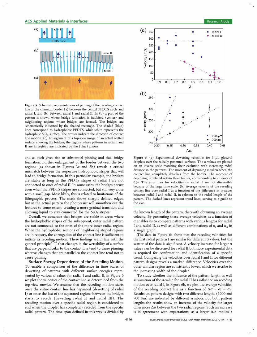
To enable a comparison of the difference in time scales ofdewetting of patterns with different surface energies repre-sented by various α-values for radial I and radial II, in Figure 6we plot the velocities of the contact line as determined from thetop-view movies. We assume that the receding motion startsonce the entire contact line has depinned (dewetting of radialI) or once the last of the separated regions between the bridgesstarts to recede (dewetting radial II and radial III). Thereceding motion over a specific radial region is considered toend when the droplet has completely receded from the specificradial pattern. The time span defined in this way is divided by
the known length of the pattern, therewith obtaining an averagevelocity. By presenting these average velocities as a function ofα enables us to compare patterns with various lengths for radialI and radial II, as well as different combinations of αI and αII ina single graph.The data in Figure 6a show that the receding velocities for
the first radial pattern I are similar for different α values, but thescatter of the data is significant. A velocity increase for larger αvalues can be discerned for radial II but more experimental datais required for confirmation and identification of a specifictrend. Comparing the velocities over radial I and II for differentpattern designs reveals a marked difference. Velocities over theouter annular region are consistently lower, which we ascribe tothe increasing width of the droplet.To study whether the influence of the pattern length as well
as variation of the α-value for radial II has influence on recedingmotion over radial I, in Figure 6b, we plot the average velocitiesof the receding contact line as a function of Δα = αI − αII.Results on pattern designs with two different lengths (1000 and700 μm) are indicated by different symbols. For both patternlengths the results show an increase of the velocity for largerdifferences Δα between the two radial regions. Such an increaseis in agreement with expectations, as a larger Δα implies a
Figure 5. Schematic representations of pinning of the receding contactline at the chemical border (a) between the central PFDTS circle andradial I, and (b) between radial I and radial II. In (b) a part of thepattern is shown where bridge formation is inhibited (center) andneighboring regions where bridges are formed. The bridges areschematically indicated by the shaded rectangle. The shaded (blue)lines correspond to hydrophobic PFDTS, while white represents thehydrophilic SiO2 surface. The arrows indicate the direction of contactline motion. (c) Enlargement of a top-view image of an actual wettedsurface, showing the bridges; the regions where patterns in radial I andII are in registry are indicated by the (blue) arrows.
Figure 6. (a) Experimental dewetting velocities for 1 μL glyceroldroplets over the radially patterned surfaces. The α-values are plottedon an inverse scale matching their evolution with increasing radialdistance in the patterns. The moment of depinning is taken when thecontact line completely detaches from the border. The moment ofdepinning is defined within three frames, corresponding to an error of0.3s. The error bars for velocities on radial II are not discerniblebecause of the large time scale. (b) Average velocity of the recedingcontact line over radial I as a function of the difference in α-valuesbetween radial I and radial II, in relation to the radial length of thepattern. The dashed lines represent trend lines, serving as a guide tothe eye.
ACS Applied Materials & Interfaces Research Article
larger difference in surface energies and corresponding drivingforce, ultimately leading to the faster movement of the dropletto the more favorable areas on the surface.Unfortunately, because of the considerable scatter of the
experimental data, it is difficult to draw conclusions concerningthe influence of the pattern length on the velocities. Thepresent results on a limited number of patterns indicate that thevelocities are higher for patterns with 1000 μm radial patternlength. More data are needed to enable a full quantitativeanalysis; this lies outside the scope of this work.
■ CONCLUSIONSInspired by potential application in inkjet printing technology, aqualitative description of glycerol droplet motion over radiallypatterned, chemically functionalized surfaces has beenpresented. The patterns considered in this article consist of ahydrophobic PFDTS circle in the center of the design,surrounded by annular striped regions consisting of radiallyoriented stripes of alternating wettabilities, i.e,. hydrophilic andhydrophobic. The anisotropic surface patterning creates apreferential direction for droplet motion away from thehydrophobic center circle onto the hydrophilic unpatternedsilicon oxide around the pattern. The relative widths of thestripes (in the micrometer range) were varied to study dropletbehavior on patterns with variable macroscopic surfaceenergies. The experimental results can be compared withprevious observations on linear patterns on which quantitativestudies were carried out. Similarities as well as differencesbetween the radial and linear patterns have been described anddiscussed. Comparing the receding velocities, we find thatoverall the motion over radial patterns is slower as compared tothat over the linear designs. Most likely, this differenceoriginates from the fact that, as compared to the linearpatterns, the radial patterns impose a less strict confinement ofthe liquid (by the hydrophobic PFDTS stripes) in the directionperpendicular to the motion of the liquid. Furthermore, specificfeatures observed on radial patterns, such as liquid bridges andresidual liquid layers on individual hydrophilic stripes thatremain after the droplet has receded over the pattern, arediscussed to identify their origin and with the distant goal toavoid their formation in future pattern designs.
■ ACKNOWLEDGMENTSWe thank Gor Manukyan (University of Twente, Physics ofComplex Fluids) for assistance with the PFDTS coating on thewafers. We gratefully acknowledge the support by MicroNed, aconsortium to nurture microsystems-technology in TheNetherlands.
■ REFERENCES(1) Williams, C. Phys. World 2006, 19, 24−29.(2) Wijshoff, H. Phys. Rep. 2010, 491, 77−177.(3) Lewis, J. A. Adv. Funct. Mater. 2006, 16, 2193−2204.(4) Pataky, K.; Braschler, T.; Negro, A.; Renaud, P.; Lutolf, M. P.;Brugger, J. Adv. Mater. 2012, 24, 391.(5) Hwang, J. Y.; Chien, L. C. Multi-Domain Liquid CrystalAlignment Based on Periodical Polyimide Micro-Bars Fabricated by
Inkjet Printing. In Proceedings of Emerging Liquid Crystal TechnologiesV; SPIE-International Society for Optical Engineering: Bellingham,WA, 2010; Vol. 7618.(6) Chen, C. T.; Wu, K. H.; Lu, C. F.; Shieh, F. J. Micromech.Microeng. 2010, 20, 055004.(7) Fousseret, B.; Mougenot, M.; Rossignol, F.; Baumard, J. F.;Soulestin, B.; Boissiere, C.; Ribot, F.; Jalabert, D.; Carrion, C.;Sanchez, C.; Lejeune, M. Chem. Mater. 2010, 22, 3875−3883.(8) Beccherelli, R.; Zampetti, E.; Pantalei, S.; Bernabei, M.; Persaud,K. C. Sens. Actuator B-Chem. 2010, 146, 446−452.(9) Cheng, Z. Y.; Xing, R. B.; Hou, Z. Y.; Huang, S. S.; Lin, J. J. Phys.Chem. C 2010, 114, 9883−9888.(10) Delaney, J. T.; Liberski, A. R.; Perelaer, J.; Schubert, U. S.Macromol. Rapid Commun. 2010, 31, 1970−1976.(11) Loffredo, F.; Del Mauro, A. D.; Burrasca, G.; La Ferrara, V.;Quercia, L.; Massera, E.; Di Francia, G.; Sala, D. D. Sens. Actuators, B2009, 143, 421−429.(12) Wu, Y.; Girgis, E.; Strom, V.; Voit, W.; Belova, L.; Rao, K. V.Phys. Status Solidi A 2010, 208, 206−209.(13) Cui, X. F.; Dean, D.; Ruggeri, Z. M.; Boland, T. Biotechnol.Bioeng. 2010, 106, 963−969.(14) Desai, S.; Perkins, J.; Harrison, B. S.; Sankar, J.Mater. Sci. Eng., B2010, 168, 127−131.(15) MEMS Inkjet printheads: new developments for growingindustrial applications. Jan 2009; http://www.yole.fr/pagesAn/micronews/newslett.asp.(16) Menzel, C.; Bibl, A.; Hoisington, P. MEMS solutions forprecision micro-fluidic dispensing application. In NIP20: InternationalConference on Digital Printing Technologies; Salt Lake City, UT, Oct2004 ; Society for Imaging Science and Technology: Springfield, VA,2004; Vol. 20; pp 169−175.(17) Jong de, J.; Bruin de, G.; Reinten, H.; Berg van den, M.;Wijshoff, H.; Versluis, M.; Lohse, D. J. Acoust. Soc. Am. 2006, 120,1257−1265.(18) Beulen, B.; de Jong, J.; Reinten, H.; van den Berg, M.; Wijshoff,H.; van Dongen, R. Exp. Fluids 2007, 42, 217−224.(19) de Jong, J.; Reinten, H.; Wijshoff, H.; van den Berg, M.;Delescen, K.; van Dongen, R.; Mugele, F.; Versluis, M.; Lohse, D.Appl. Phys. Lett. 2007, 91, 204102.(20) van der Bos, A.; Segers, T.; Jeurissen, R.; van den Berg, M.;Reinten, H.; Wijshoff, H.; Versluis, M.; Lohse, D. Appl. Phys. Lett.2011, 110, 034503.(21) Chen, Y. M.; Mertz, R.; Kulenovic, R. Int. J. Multiphase Flow2009, 35, 66−77.(22) Chun-Fu, L.; Wen-Chieh, L.; Chun-Jung, C.; Chien-Chung, F.Anti-wetting trench of nozzle plate for piezoelectric actuatingdispenser. In 4th International Microsystems, Packaging, Assembly andCircuits Technology Conference (IMPACT 2009); Taipei, Taiwan, Oct21−23, 2009 ; .Institute of Electrical and Electronics Engineers(IEEE): Piscataway, NJ, 2009; pp 674−677.(23) Chaudhury, M. K.; Whitesides, G. M. Science 1992, 256, 1539.(24) Hong, D.; Cho, W. K.; Kong, B.; Choi, I. S. Langmuir 2010, 26,15080.(25) Das, A. K.; Das, P. K. Langmuir 2010, 26, 15883.(26) Wu, J.; Ma, R.; Wang, Z.; Yao, S. Appl. Phys. Lett. 2011, 98,204104.(27) Zhang, Y.; Pi, P. H.; Wen, X. F.; Zheng, D. F.; Cai, Z. Q.;Cheng, J. Prog. Chem. 2011, 23, 2457.(28) Neuhaus, S.; Padesta, C.; Spencer, N. D. Langmuir 2011, 27,6855.(29) Hao, P. F.; Lv, C. J.; Zhang, X. W.; Yao, Z. H.; He, F. Chem. Eng.Sci. 2011, 66, 2118.(30) Moosavi, A.; Mohammadi, A. J. Phys.: Condens. Matter 2011, 23,085004.(31) Neuhaus, S.; Spencer, N. D.; Padeste, C. ACS Appl. Mater.Interface 2012, 4, 123.(32) Xu, X.; Qian, T. Phys. Rev. E 2012, 85, 051601.(33) Darhuber, A. A.; Troian, S. M. Annu. Rev. Fluid Mech. 2005, 37,425.
ACS Applied Materials & Interfaces Research Article
(34) Herminghaus, S.; Brinkmann, M.; Seemann, R. Annu. Rev.Mater. Res. 2008, 38, 101.(35) Xia, D.; Johnson, L. M.; Lopez, G. P. Adv. Mater. 2012, 24,1287−1302.(36) Hancock, M. J.; Sekeroglu, K.; Demirel, M. C. Adv. Funct. Mater.2012, 22, 2223.(37) Bliznyuk, O.; Jansen, H. P.; Kooij, E. S.; Zandvliet, H. J. W.;Poelsema, B. Langmuir 2011, 27, 11238−11245.(38) David, R.; Neumann, A. W. Colloids Surf., A 2012, 399, 41−45.(39) David, R.; Neumann, A. W. Colloids Surf., A 2012, 393, 32−36.(40) Rathgen, H. Superhydrophobic surfaces: from fluid mechanicsto optics. Ph.D. Thesis, University of Twente, Enschede, TheNetherlands, 2008.(41) Bliznyuk, O.; Vereshchagina, E.; Kooij, E. S.; Poelsema, B. Phys.Rev. E 2009, 79, 041601.(42) Bliznyuk, O.; Jansen, H. P.; Kooij, E. S.; Poelsema, B. Langmuir2010, 26, 6328−6334.(43) Elwing, H.; Welin, S.; Askendal, A.; Nilsson, U.; Lundstrom, I. J.Colloid Interface Sci. 1987, 119, 203−210.(44) Hlady, V.; Golander, C.; Andrade, J. D. Colloids Surf. 1988, 33,185−190.(45) Mechkov, S.; Rauscher, M.; Dietrich, S. Phys. Rev. E 2008, 77,061605.(46) Brinkmann, M.; Kierfeld, J.; Lipowsky, R. J. Phys. A 2004, 37,11547.(47) Johnson, R. E.; Dettre, R. H. J. Phys. Chem. 1964, 68, 1744.(48) Kusumaatmaja, H.; Vrancken, R. J.; Bastiaansen, C. W. M.;Yeomans, J. M. Langmuir 2008, 24, 7299.
ACS Applied Materials & Interfaces Research Article