64
DIRIS B-10 & B-30 Multifunction meters and associated current sensors EN INSTRUCTION MANUAL www.socomec.com/ en/diris-b

DIRIS B-10 & B-30Multifunction meters and associated
current sensorsEN
INSTRUCTION
MANUAL
www.socomec.com/en/diris-b
2 EN DIRIS B - 546 770 A - SOCOMEC
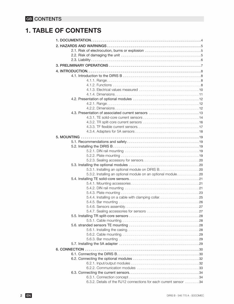
1. TABLE OF CONTENTS
1. DOCUMENTATION . . . . . . . . . . . . . . . . . . . . . . . . . . . . . . . . . . . . . . . . . . . . . . . . . . . . . . . 4
2. HAZARDS AND WARNINGS . . . . . . . . . . . . . . . . . . . . . . . . . . . . . . . . . . . . . . . . . . . . . . . 5
2.1. Risk of electrocution, burns or explosion . . . . . . . . . . . . . . . . . . . . . . . . . . . . 5
2.2. Risk of damaging the unit . . . . . . . . . . . . . . . . . . . . . . . . . . . . . . . . . . . . . . . . 5
2.3. Liability . . . . . . . . . . . . . . . . . . . . . . . . . . . . . . . . . . . . . . . . . . . . . . . . . . . . . . . 6
3. PRELIMINARY OPERATIONS . . . . . . . . . . . . . . . . . . . . . . . . . . . . . . . . . . . . . . . . . . . . . . 7
4. INTRODUCTION . . . . . . . . . . . . . . . . . . . . . . . . . . . . . . . . . . . . . . . . . . . . . . . . . . . . . . . . . 8
. . . . . . . . . . . . . . . . . . . . . . . . . . . . . . . . . . . . . . . 8
4.1.1. Range . . . . . . . . . . . . . . . . . . . . . . . . . . . . . . . . . . . . . . . . . . . . . . . 8
4.1.2. Functions . . . . . . . . . . . . . . . . . . . . . . . . . . . . . . . . . . . . . . . . . . . . 8
4.1.3. Electrical values measured . . . . . . . . . . . . . . . . . . . . . . . . . . . . . . 10
4.1.4. Dimensions . . . . . . . . . . . . . . . . . . . . . . . . . . . . . . . . . . . . . . . . . . 11
4.2. Presentation of optional modules . . . . . . . . . . . . . . . . . . . . . . . . . . . . . . . . . 12
4.2.1. Range . . . . . . . . . . . . . . . . . . . . . . . . . . . . . . . . . . . . . . . . . . . . . . 12
4.2.2. Dimensions . . . . . . . . . . . . . . . . . . . . . . . . . . . . . . . . . . . . . . . . . . 12
4.3. Presentation of associated current sensors . . . . . . . . . . . . . . . . . . . . . . . . . 13
4.3.1. TE solid-core current sensors . . . . . . . . . . . . . . . . . . . . . . . . . . . . 14
4.3.2. TR split-core current sensors . . . . . . . . . . . . . . . . . . . . . . . . . . . . 16
4.3.3. TF flexible current sensors . . . . . . . . . . . . . . . . . . . . . . . . . . . . . . . 17
4.3.4. Adapters for 5A sensors . . . . . . . . . . . . . . . . . . . . . . . . . . . . . . . . 18
5. MOUNTING . . . . . . . . . . . . . . . . . . . . . . . . . . . . . . . . . . . . . . . . . . . . . . . . . . . . . . . . . . . 19
5.1. Recommendations and safety . . . . . . . . . . . . . . . . . . . . . . . . . . . . . . . . . . . . 19
. . . . . . . . . . . . . . . . . . . . . . . . . . . . . . . . . . . . . . . . . . . 19
5.2.1. DIN rail mounting . . . . . . . . . . . . . . . . . . . . . . . . . . . . . . . . . . . . . 19
5.2.2. Plate mounting . . . . . . . . . . . . . . . . . . . . . . . . . . . . . . . . . . . . . . . 19
5.2.3. Sealing accessory for sensors . . . . . . . . . . . . . . . . . . . . . . . . . . . . 20
5.3. Installing the optional modules . . . . . . . . . . . . . . . . . . . . . . . . . . . . . . . . . . . 20
5.3.1. Installing an optional module on DIRIS B . . . . . . . . . . . . . . . . . . . . 20
5.3.2. Installing an optional module on an optional module . . . . . . . . . . . 20
5.4. Installing TE solid-core sensors . . . . . . . . . . . . . . . . . . . . . . . . . . . . . . . . . . . 21
5.4.1. Mounting accessories . . . . . . . . . . . . . . . . . . . . . . . . . . . . . . . . . . 21
5.4.2. DIN rail mounting . . . . . . . . . . . . . . . . . . . . . . . . . . . . . . . . . . . . . 21
5.4.3. Plate mounting . . . . . . . . . . . . . . . . . . . . . . . . . . . . . . . . . . . . . . . 23
5.4.4. Installing on a cable with clamping collar . . . . . . . . . . . . . . . . . . . . 25
5.4.5. Bar mounting . . . . . . . . . . . . . . . . . . . . . . . . . . . . . . . . . . . . . . . . 26
5.4.6. Sensors assembly . . . . . . . . . . . . . . . . . . . . . . . . . . . . . . . . . . . . . 27
5.4.7. Sealing accessories for sensors . . . . . . . . . . . . . . . . . . . . . . . . . . 27
5.5. Installing TR split-core sensors . . . . . . . . . . . . . . . . . . . . . . . . . . . . . . . . . . . 28
5.5.1. Cable mounting . . . . . . . . . . . . . . . . . . . . . . . . . . . . . . . . . . . . . . . 28
5.6. stranded sensors TE mounting . . . . . . . . . . . . . . . . . . . . . . . . . . . . . . . . . . . 28
5.6.1. Installing the casing . . . . . . . . . . . . . . . . . . . . . . . . . . . . . . . . . . . . 28
5.6.2. Cable mounting . . . . . . . . . . . . . . . . . . . . . . . . . . . . . . . . . . . . . . . 29
5.6.3. Bar mounting . . . . . . . . . . . . . . . . . . . . . . . . . . . . . . . . . . . . . . . . 29
5.7. Installing the 5A adapter . . . . . . . . . . . . . . . . . . . . . . . . . . . . . . . . . . . . . . . . 29
6. CONNECTION . . . . . . . . . . . . . . . . . . . . . . . . . . . . . . . . . . . . . . . . . . . . . . . . . . . . . . . . . 30
. . . . . . . . . . . . . . . . . . . . . . . . . . . . . . . . . . . . . . . . . 30
6.2. Connecting the optional modules . . . . . . . . . . . . . . . . . . . . . . . . . . . . . . . . . 32
6.2.1. Input/output modules . . . . . . . . . . . . . . . . . . . . . . . . . . . . . . . . . . 32
6.2.2. Communication modules . . . . . . . . . . . . . . . . . . . . . . . . . . . . . . . 33
6.3. Connecting the current sensors . . . . . . . . . . . . . . . . . . . . . . . . . . . . . . . . . . . 34
6.3.1. Connection concept . . . . . . . . . . . . . . . . . . . . . . . . . . . . . . . . . . . 34
6.3.2. Details of the RJ12 connections for each current sensor . . . . . . . 34
GB CONTENTS
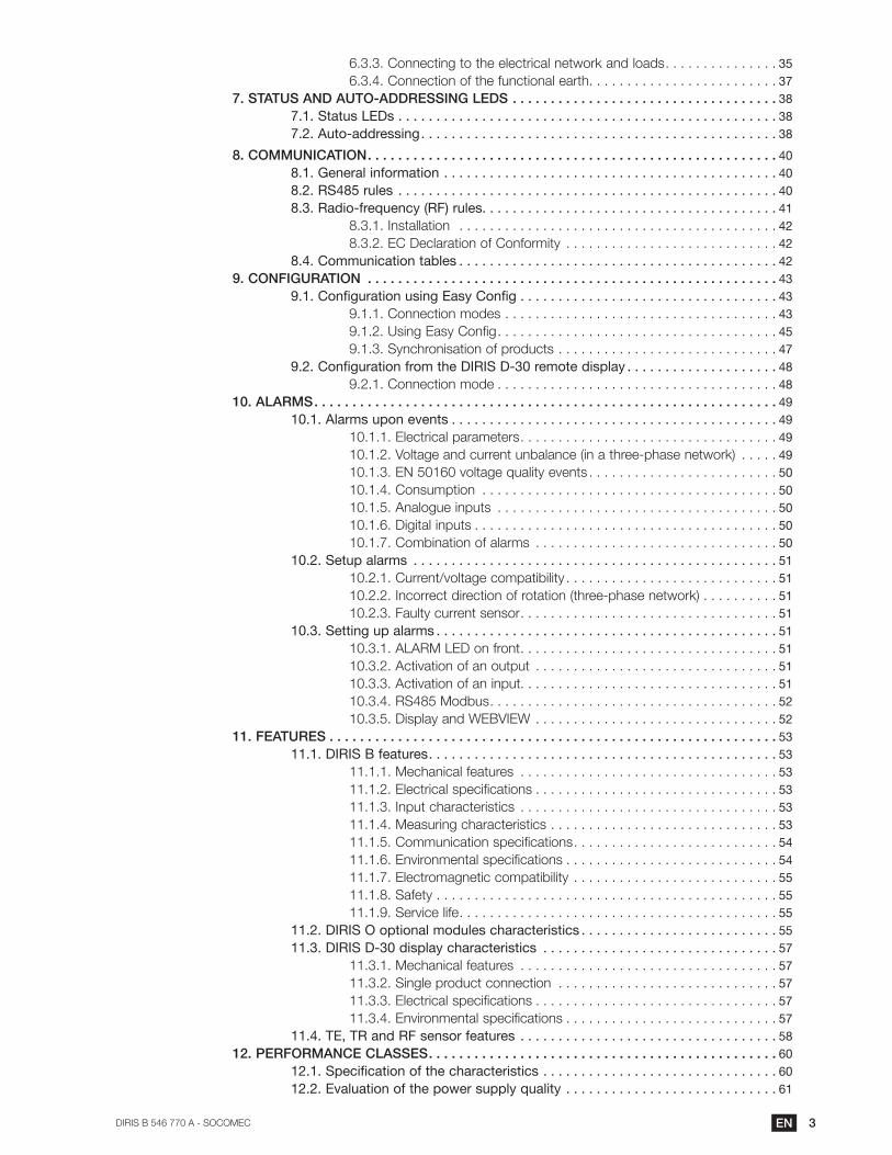
3ENDIRIS B 546 770 A - SOCOMEC
6.3.3. Connecting to the electrical network and loads . . . . . . . . . . . . . . . 35
6.3.4. Connection of the functional earth . . . . . . . . . . . . . . . . . . . . . . . . . 37
7. STATUS AND AUTO-ADDRESSING LEDS . . . . . . . . . . . . . . . . . . . . . . . . . . . . . . . . . . . 38
7.1. Status LEDs . . . . . . . . . . . . . . . . . . . . . . . . . . . . . . . . . . . . . . . . . . . . . . . . . . 38
7.2. Auto-addressing . . . . . . . . . . . . . . . . . . . . . . . . . . . . . . . . . . . . . . . . . . . . . . . 38
8. COMMUNICATION . . . . . . . . . . . . . . . . . . . . . . . . . . . . . . . . . . . . . . . . . . . . . . . . . . . . . . 40
8.1. General information . . . . . . . . . . . . . . . . . . . . . . . . . . . . . . . . . . . . . . . . . . . . 40
8.2. RS485 rules . . . . . . . . . . . . . . . . . . . . . . . . . . . . . . . . . . . . . . . . . . . . . . . . . . 40
8.3. Radio-frequency (RF) rules. . . . . . . . . . . . . . . . . . . . . . . . . . . . . . . . . . . . . . . 41
. . . . . . . . . . . . . . . . . . . . . . . . . . . . . . . . . . . . . . . . . . 42
8.3.2. EC Declaration of Conformity . . . . . . . . . . . . . . . . . . . . . . . . . . . . 42
8.4. Communication tables . . . . . . . . . . . . . . . . . . . . . . . . . . . . . . . . . . . . . . . . . . 42
9. CONFIGURATION . . . . . . . . . . . . . . . . . . . . . . . . . . . . . . . . . . . . . . . . . . . . . . . . . . . . . . 43
9.1. Configuration using Easy Config . . . . . . . . . . . . . . . . . . . . . . . . . . . . . . . . . . 43
9.1.1. Connection modes . . . . . . . . . . . . . . . . . . . . . . . . . . . . . . . . . . . . 43
9.1.2. Using Easy Config . . . . . . . . . . . . . . . . . . . . . . . . . . . . . . . . . . . . . 45
9.1.3. Synchronisation of products . . . . . . . . . . . . . . . . . . . . . . . . . . . . . 47
9.2. Configuration from the DIRIS D-30 remote display . . . . . . . . . . . . . . . . . . . . 48
9.2.1. Connection mode . . . . . . . . . . . . . . . . . . . . . . . . . . . . . . . . . . . . . 48
10. ALARMS . . . . . . . . . . . . . . . . . . . . . . . . . . . . . . . . . . . . . . . . . . . . . . . . . . . . . . . . . . . . . 49
10.1. Alarms upon events . . . . . . . . . . . . . . . . . . . . . . . . . . . . . . . . . . . . . . . . . . . 49
10.1.1. Electrical parameters . . . . . . . . . . . . . . . . . . . . . . . . . . . . . . . . . . 49
10.1.2. Voltage and current unbalance (in a three-phase network) . . . . . 49
10.1.3. EN 50160 voltage quality events . . . . . . . . . . . . . . . . . . . . . . . . . 50
10.1.4. Consumption . . . . . . . . . . . . . . . . . . . . . . . . . . . . . . . . . . . . . . . 50
10.1.5. Analogue inputs . . . . . . . . . . . . . . . . . . . . . . . . . . . . . . . . . . . . . 50
10.1.6. Digital inputs . . . . . . . . . . . . . . . . . . . . . . . . . . . . . . . . . . . . . . . . 50
10.1.7. Combination of alarms . . . . . . . . . . . . . . . . . . . . . . . . . . . . . . . . 50
10.2. Setup alarms . . . . . . . . . . . . . . . . . . . . . . . . . . . . . . . . . . . . . . . . . . . . . . . . 51
10.2.1. Current/voltage compatibility . . . . . . . . . . . . . . . . . . . . . . . . . . . . 51
10.2.2. Incorrect direction of rotation (three-phase network) . . . . . . . . . . 51
10.2.3. Faulty current sensor . . . . . . . . . . . . . . . . . . . . . . . . . . . . . . . . . . 51
10.3. Setting up alarms . . . . . . . . . . . . . . . . . . . . . . . . . . . . . . . . . . . . . . . . . . . . . 51
10.3.1. ALARM LED on front . . . . . . . . . . . . . . . . . . . . . . . . . . . . . . . . . . 51
10.3.2. Activation of an output . . . . . . . . . . . . . . . . . . . . . . . . . . . . . . . . 51
10.3.3. Activation of an input. . . . . . . . . . . . . . . . . . . . . . . . . . . . . . . . . . 51
10.3.4. RS485 Modbus . . . . . . . . . . . . . . . . . . . . . . . . . . . . . . . . . . . . . . 52
10.3.5. Display and WEBVIEW . . . . . . . . . . . . . . . . . . . . . . . . . . . . . . . . 52
11. FEATURES . . . . . . . . . . . . . . . . . . . . . . . . . . . . . . . . . . . . . . . . . . . . . . . . . . . . . . . . . . . 53
. . . . . . . . . . . . . . . . . . . . . . . . . . . . . . . . . . . . . . . . . . . . . . 53
11.1.1. Mechanical features . . . . . . . . . . . . . . . . . . . . . . . . . . . . . . . . . . 53
11.1.2. Electrical specifications . . . . . . . . . . . . . . . . . . . . . . . . . . . . . . . . 53
11.1.3. Input characteristics . . . . . . . . . . . . . . . . . . . . . . . . . . . . . . . . . . 53
11.1.4. Measuring characteristics . . . . . . . . . . . . . . . . . . . . . . . . . . . . . . 53
11.1.5. Communication specifications . . . . . . . . . . . . . . . . . . . . . . . . . . . 54
11.1.6. Environmental specifications . . . . . . . . . . . . . . . . . . . . . . . . . . . . 54
11.1.7. Electromagnetic compatibility . . . . . . . . . . . . . . . . . . . . . . . . . . . 55
11.1.8. Safety . . . . . . . . . . . . . . . . . . . . . . . . . . . . . . . . . . . . . . . . . . . . . 55
11.1.9. Service life . . . . . . . . . . . . . . . . . . . . . . . . . . . . . . . . . . . . . . . . . . 55
11.2. DIRIS O optional modules characteristics . . . . . . . . . . . . . . . . . . . . . . . . . . 55
11.3. DIRIS D-30 display characteristics . . . . . . . . . . . . . . . . . . . . . . . . . . . . . . . 57
11.3.1. Mechanical features . . . . . . . . . . . . . . . . . . . . . . . . . . . . . . . . . . 57
11.3.2. Single product connection . . . . . . . . . . . . . . . . . . . . . . . . . . . . . 57
11.3.3. Electrical specifications . . . . . . . . . . . . . . . . . . . . . . . . . . . . . . . . 57
11.3.4. Environmental specifications . . . . . . . . . . . . . . . . . . . . . . . . . . . . 57
11.4. TE, TR and RF sensor features . . . . . . . . . . . . . . . . . . . . . . . . . . . . . . . . . . 58
12. PERFORMANCE CLASSES . . . . . . . . . . . . . . . . . . . . . . . . . . . . . . . . . . . . . . . . . . . . . . 60
12.1. Specification of the characteristics . . . . . . . . . . . . . . . . . . . . . . . . . . . . . . . 60
12.2. Evaluation of the power supply quality . . . . . . . . . . . . . . . . . . . . . . . . . . . . 61

4 EN DIRIS B - 546 770 A - SOCOMEC
1. DOCUMENTATION
sensors is available on the SOCOMEC website at the following
address:
www.socomec.com/en/diris-b
5ENDIRIS B 546 770 A - SOCOMEC
2. HAZARDS AND WARNINGS
professionals.
SOCOMEC shall not be held responsible for failure to comply with the instructions in this manual.
2.1. Risk of electrocution, burns or explosion
Caution: risk of electric shock Ref. ISO 7000-0434B (2004-01)
Caution Refer to the accompanying documentation each time this symbol is shown
Ref. ISO 7000-0434B (2004-01)
commissioning and operating the device and who have had appropriate training. He or she should have read and understood the various safety measures and warnings stated in the instructions.
Always power the device with the correct rated voltage.
Install the unit following the recommended installation instructions and in a suitable electrical cabinet.
maximum prescribed currents.
Do NOT clamp or pull out NON-INSULATED conductors carrying DANGEROUS VOLTAGE which
Ref. IEC 61010-2-032
Failure to take these precautions could cause death or serious injuries.
2.2. Risk of damaging the unit
Caution: risk of electric shock Ref. ISO 7000-0434B (2004-01)
Caution Refer to the accompanying documentation each time this symbol is shown
Ref. ISO 7000-0434B (2004-01)
The unit is correctly installed.
The network frequency indicated on the device is observed: 50 or 60 Hz.
A maximum voltage at the voltage input terminals of 520 VAC phase/phase or 300 VAC phase/neutral is observed.
maximum prescribed currents.
Failure to respect these precautions could cause damage to the unit.

6 EN DIRIS B - 546 770 A - SOCOMEC
2.3. Liability
The unit must be installed in accordance with the rules given in this manual.
The unit must be positioned within an installation which complies with the standards currently in force.
Any cables which need to be replaced may only be replaced with cables with the correct ratings.

7ENDIRIS B 546 770 A - SOCOMEC
3. PRELIMINARY OPERATIONS
installation.
The packaging is in good condition
The unit has not been damaged during transportation
The device reference conforms to your order

8 EN DIRIS B - 546 770 A - SOCOMEC
4. INTRODUCTION
4.1.
It can be used to jointly analyse the single-phase and three-phase loads. Add optional modules to manage multi-
can be guaranteed for all values measured.
Energy Monitoring version). The data can also be accessed via the HYPERVIEW energy management software.
The communication modes RS485 Modbus or radio frequency are available depending on the DIRIS B reference.
management system.
*PMD: Performance Measuring and Monitoring Device in accordance with IEC 61557-12.
4.1.1. Range
PMD DIRIS B-10 DIRIS B-30 RS DIRIS B-30 RF
Communication RS485
RF
Ref. 4829 0010
Accessories
Height: 210mmCable for remote antenna. Sealing kit. USB cable for configuration
4.1.2. Functions
9ENDIRIS B 546 770 A - SOCOMEC
-
-
- Operation across 4 quadrants
- Predictive power
-current sensor used) for active energy and power in accordance with IEC 61557-12
-
- THD and harmonics up to order 63 for voltage and current
-
- Current and voltage imbalance
-
Data logging
- Recording of average electrical values
- Recording and timestamping of min/max electrical values
Metering
-
-
- Multi-tariff
Alarm (*)
- 25 timestamped alarms with boolean combination
Connection
- 4 current inputs with automatic recognition of the current sensors via a quick connection cable (RJ12 type)
-
-
-energy as per IEC 61557-12
Inputs / Outputs
- 2 logical inputs
-
Communication
- RS485 or radio frequency (RF) communication (see reference)
-
- Connects to a DIRIS D-30 remote display via RJ9 or D-50 / D-70 via RS485
-
- Time synchronisation with the gateway
- Auto-addressing in association with the gateway
(*) Available only on the DIRIS B-30 RS (ref. 4829 0000) and DIRIS B-30 RF (ref. 4829 0002)
10 EN DIRIS B - 546 770 A - SOCOMEC
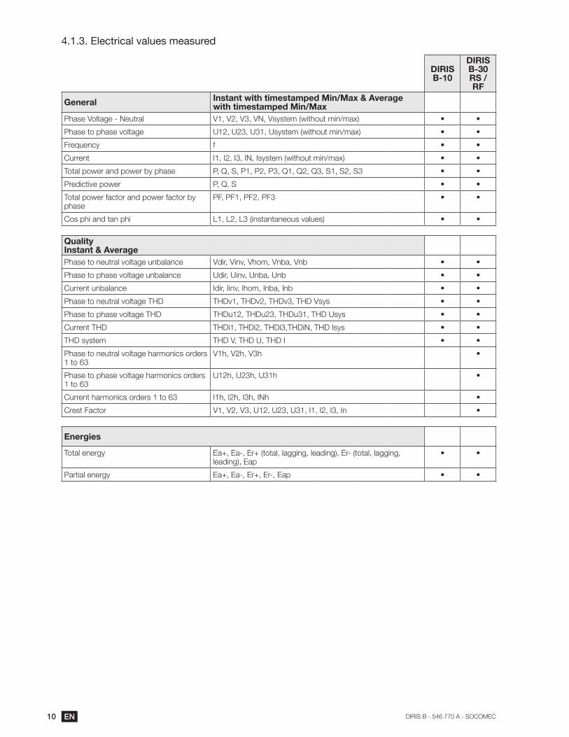
4.1.3. Electrical values measured
DIRIS B-10
DIRIS B-30RS / RF
GeneralInstant with timestamped Min/Max & Average with timestamped Min/Max
Phase Voltage - Neutral
Phase to phase voltage
Frequency f
Current
Total power and power by phase
Predictive power
Total power factor and power factor by phase
Cos phi and tan phi
QualityInstant & Average
Phase to neutral voltage unbalance
Phase to phase voltage unbalance
Current unbalance
Phase to neutral voltage THD
Phase to phase voltage THD
Current THD
THD system
Phase to neutral voltage harmonics orders 1 to 63
Phase to phase voltage harmonics orders 1 to 63
Current harmonics orders 1 to 63
Crest Factor
Energies
Total energy
Partial energy
11ENDIRIS B 546 770 A - SOCOMEC
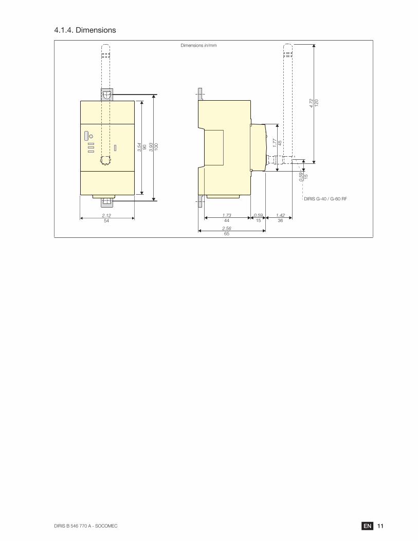
4.1.4. Dimensions
2.12
54
3.54
90
3.93
100 1.77
45
4.72
120
0.59
15
1.73
440.59
15
2.56
65
1.42
36
DIRIS G-40 / G-60 RF
Dimensions in/mm
12 EN DIRIS B - 546 770 A - SOCOMEC
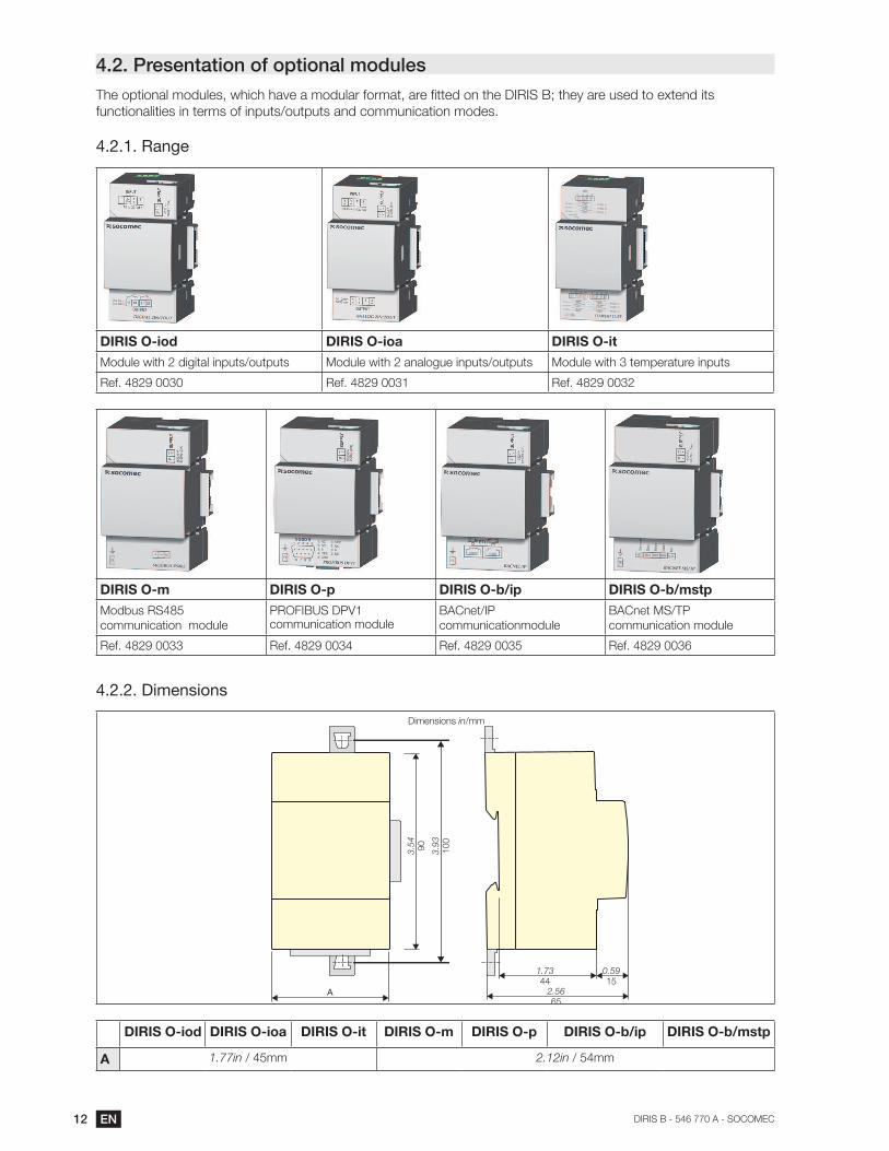
4.2. Presentation of optional modules
functionalities in terms of inputs/outputs and communication modes.
4.2.1. Range
DIRIS O-iod DIRIS O-ioa DIRIS O-it
Module with 2 digital inputs/outputs Module with 2 analogue inputs/outputs Module with 3 temperature inputs
DIRIS O-m DIRIS O-p DIRIS O-b/ip DIRIS O-b/mstp
Modbus RS485
communication module
PROFIBUS DPV1 communication module
BACnet/IP
communicationmodule
BACnet MS/TP
communication module
4.2.2. Dimensions
Dimensions in/mm
A
3.54
90
3.93
10
0
1.73
440.59
152.56
65
DIRIS O-iod DIRIS O-ioa DIRIS O-it DIRIS O-m DIRIS O-p DIRIS O-b/ip DIRIS O-b/mstp
A 1.77in / 45mm 2.12in / 54mm

13ENDIRIS B 546 770 A - SOCOMEC
4.3. Presentation of associated current sensors
chain.
DIRIS B
TE / TR / TF current sensors
Recommendations:
It is recommended that all the current sensors are installed in the same direction.
Connection cables for current sensors:
RJ12 connection cables
Cable length (m)
0.1 0.2 0.3 0.5 1 2 5 10 + 100 connectors*
Number of cables
reference reference reference reference reference reference reference reference reference
1 - - - - - - 4829 0602 4829 0603 4829 0601
3 4829 0580 4829 0581 4829 0582 4829 0595 4829 0583 4829 0584 - - -
4 4829 0596 4829 0588 4829 0589 - - -
6 4829 0590 4829 0591 4829 0592 4829 0597 4829 0593 4829 0594 - - -

14 EN DIRIS B - 546 770 A - SOCOMEC
4.3.1. TE solid-core current sensors
The TE solid-core current sensors are used to set up measurement points in a new or existing installation. They are
easy to integrate as they are compact and respect the pitch of the circuit breakers. A wide range of accessories are
is guaranteed.
4.3.1.1. Range
TE-18 TE-18 TE-25 TE-35 TE-45 TE-55
Pitch 18 mm 18 mm 25 mm 35 mm 45 mm 55 mm
Nominal current range In
Actual range
0.1 - 24 A 0.5 - 75 A 0.8 - 192 A 1.26 - 300 A 3.2 - 756 A 8 - 1200 A
Maximum l
Reference 4829 0500 4829 0501 4829 0502 4829 0503 4829 0504 4829 0505
TE-90
Pitch 90 mm
Nominal current range In
Actual range
12 - 2400 A
Maximum l
Reference 4829 0506
15ENDIRIS B 546 770 A - SOCOMEC
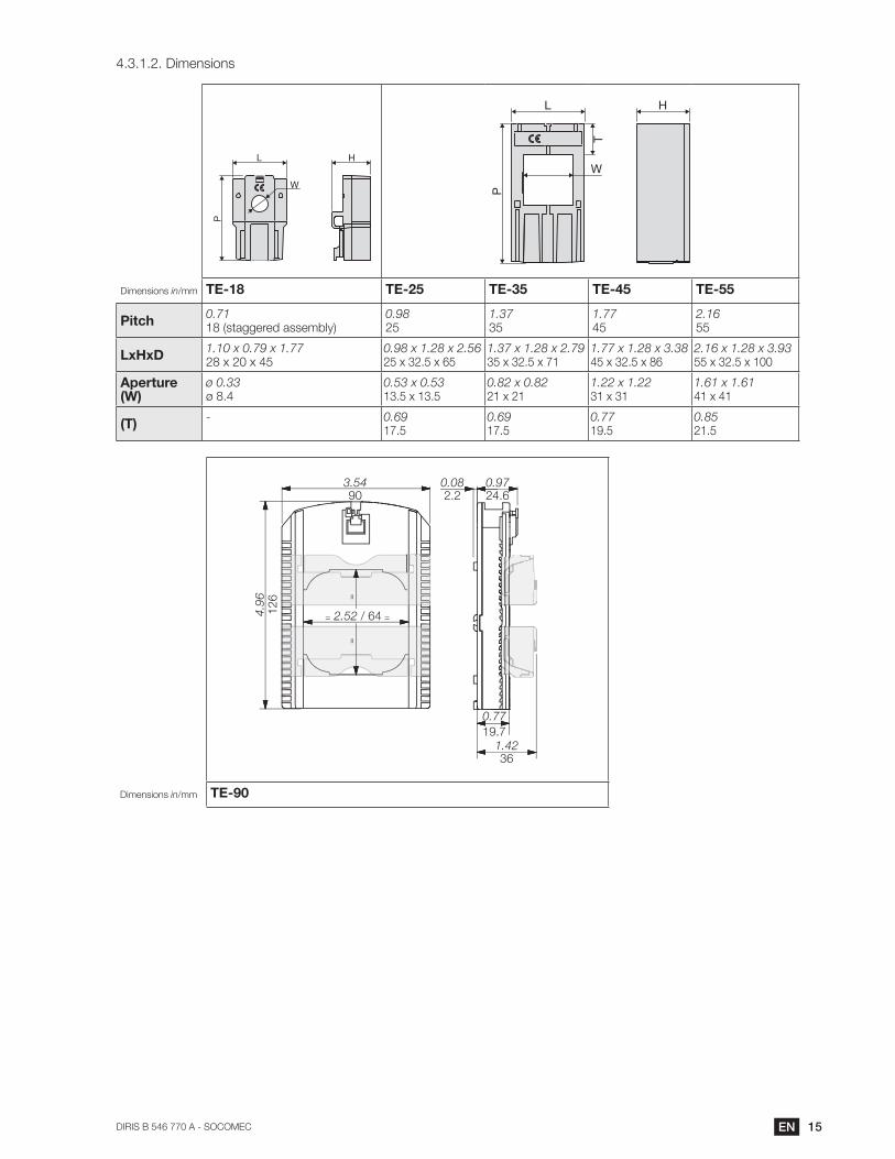
4.3.1.2. Dimensions
L H
P
W
L H
L
W
P
T
H
Dimensions in/mm TE-18 TE-25 TE-35 TE-45 TE-55
Pitch0.7118 (staggered assembly)
0.9825
1.3735
1.7745
2.1655
LxHxD1.10 x 0.79 x 1.7728 x 20 x 45
0.98 x 1.28 x 2.5625 x 32.5 x 65
1.37 x 1.28 x 2.7935 x 32.5 x 71
1.77 x 1.28 x 3.3845 x 32.5 x 86
2.16 x 1.28 x 3.9355 x 32.5 x 100
Aperture (W)
ø 0.33ø 8.4
0.53 x 0.5313.5 x 13.5
0.82 x 0.8221 x 21
1.22 x 1.2231 x 31
1.61 x 1.6141 x 41
(T)- 0.69
17.50.6917.5
0.7719.5
0.8521.5
3.54
900.08
2.2
0.77
19.7
1.42
36
=
==
= 2.52 / 644.96
126
0.97
24.6
Dimensions in/mm TE-90

16 EN DIRIS B - 546 770 A - SOCOMEC
4.3.2. TR split-core current sensors
The TR split-core current sensors are used to set up measurement points in a new or existing installation without
of the measurement chain is guaranteed.
4.3.2.1. Range
Four models are available from 25A to 600A to analyse several types of loads.
TR-10 TR-16 TR-24 TR-36
Cable passage diameter
10mm 16mm 24mm 36mm
Nominal current range In
25 - 75 A 32 - 100 A 63 - 200 A 200 - 600 A
Actual range
0.5 - 90 A 0.64 - 120 A 1.26 - 200 A 4 - 720 A
Maximum l 90A 120A 240A 720A
Reference 4829 0551 4829 0552 4829 0553 4829 0554
4.3.2.2. Dimensions
PA
L
Ø W
CB
H
Dimensions in/mm TR-10 TR-16 TR-24 TR-36
LxHxD0.98 x 1.54 x 2.7925 x 39 x 71
1.18 x 1.65 x 2.9130 x 42 x 74
1.77 x 1.73 x 3.7445 x 44 x 95
2.24 x 1.65 x 4.3757 x 42 x 111
W0.3910
0.6316
0.9424
1.4236
A2.2858
2.4061
2.8372
3.2382
B0.5714.5
0.7519
0.8722
0.8722
C1.0226
1.2231
1.3434
1.5940.5

17ENDIRIS B 546 770 A - SOCOMEC
4.3.3.
without saturation. Flexible design and easy-opening system for quick installation in electrical enclosures. They are
particularly suitable for adding measuring points in existing installations and for test campaigns.
4.3.3.1. Range
sizes.
TF-55 TF-120 TF-300
Loop length 55 mm 120 mm 300 mm
Nominal current range In
Actual range
3 - 720 A 10 - 2400 A 32 - 7200 A
Reference 4829 0570 4829 0571 4829 0572
4.3.3.2. Dimensions
0.71
18
3.34
85
E
p Ø
L L
0.71
18
3.34
85
1.49
38
E
p
Ø
L L
Dimensions in/mm TF-55 TF-120 TF-300
Diameter 2.1655
4.72120
11.81300
p7.16182
14.80376
37.08942
T0.236
0.4311
0.4311
L59.051500
18 EN DIRIS B - 546 770 A - SOCOMEC
4.3.4. Adapters for 5A sensors
The adapter lets you use a standard sensor supplying a 1A or 5A current to the secondary sensor. When this kind
of the associated sensor (see standard "norm IEC 61557-12 annex D" for more information).
4.3.4.1. Range
5A adapter
I nom. 5A
I max. 6A
Reference 4829 0599
4.3.4.2. Dimensions
L H
P
W
L H
Dimensions in/mm 5A adapter
LxHxD1.10 x 0.79 x 1.7728 x 20 x 45
Aperture (W)
ø 0.33ø 8.4
19ENDIRIS B 546 770 A - SOCOMEC
5. MOUNTING
5.1. Recommendations and safety
5.2. Installing the DIRIS B
5.2.1. DIN rail mounting
Mounting Removal
1
2
0.29 or 0.597.5 or 15
1.38 35
1 2
5.2.2. Plate mounting
0.19 in
5 mm
3.9
4 in
10
0 m
m
Type of screw: M4
Tightening torque: 0.5 Nm
Washer: maximum diameter
0.47in/12mm

20 EN DIRIS B - 546 770 A - SOCOMEC
5.2.3. Sealing accessory for sensors
Reference Sealing case for terminal
4829 0600 x20
1
3
4
2
5.3. Installing the optional modules
5.3.1.
1 3 4
Optional module
2
5.3.2. Installing an optional module on an optional module
Optional module
1 3 4
Optional module
2 Optional module

21ENDIRIS B 546 770 A - SOCOMEC
The following guidelines for installation must be observed:
One single temperature module (DIRIS O-it) may be used.
One single RS485 communication module (DIRIS O-m) may be used and must always be positioned last during installation
5.4. Installing TE solid-core sensors
5.4.1. Mounting accessories
The list of mounting accessories supplied with the sensors are listed below:
Reference PitchDIN rail and plate
mountingDIN rail mounting Plate mounting Busbar mounting
4829 0500 4829 0501
TE-18 18 mm x 1
4829 0502 TE-25 25 mm x 2 x 4
4829 0503 TE-35 35 mm x 2 x 4 x 2
4829 0504 TE-45 45 mm x 2 x 4 x 2
4829 0505 TE-55 55 mm x 2 x 4 x 2
4829 0506 TE-90 90 mm x 2 x 6
5.4.2. DIN rail mounting
TE-18 -> TE-55
22 EN DIRIS B - 546 770 A - SOCOMEC
TE-90
2
1
Removing clamps
oror
NB: Install sensor TE-90 to the DIN rail to make it easier to install. This is a temporary installation.
Use the clamps to install the TE-90 sensors on the DIN rail.

23ENDIRIS B 546 770 A - SOCOMEC
5.4.3. Plate mounting
TE-18
1x
0.17 /
0.81
20.5
1.05
26.8
1
1
2
2
2
2
3
3
TE-25 - > TE-55
4x
0.20
/
24 EN DIRIS B - 546 770 A - SOCOMEC
TE-90
2
1
Removing clamps
x6
diameter 0.20
diameter 5.2
NB: Use the clamps to install the TE-90 sensors on the board.
25ENDIRIS B 546 770 A - SOCOMEC
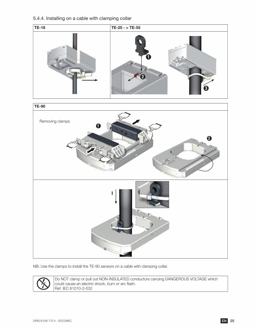
5.4.4. Installing on a cable with clamping collar
TE-18 TE-25 - > TE-55
2
3
1
TE-90
2
1
Removing clamps
I
NB: Use the clamps to install the TE-90 sensors on a cable with clamping collar.
Do NOT clamp or pull out NON-INSULATED conductors carrying DANGEROUS VOLTAGE which
Ref. IEC 61010-2-032
26 EN DIRIS B - 546 770 A - SOCOMEC
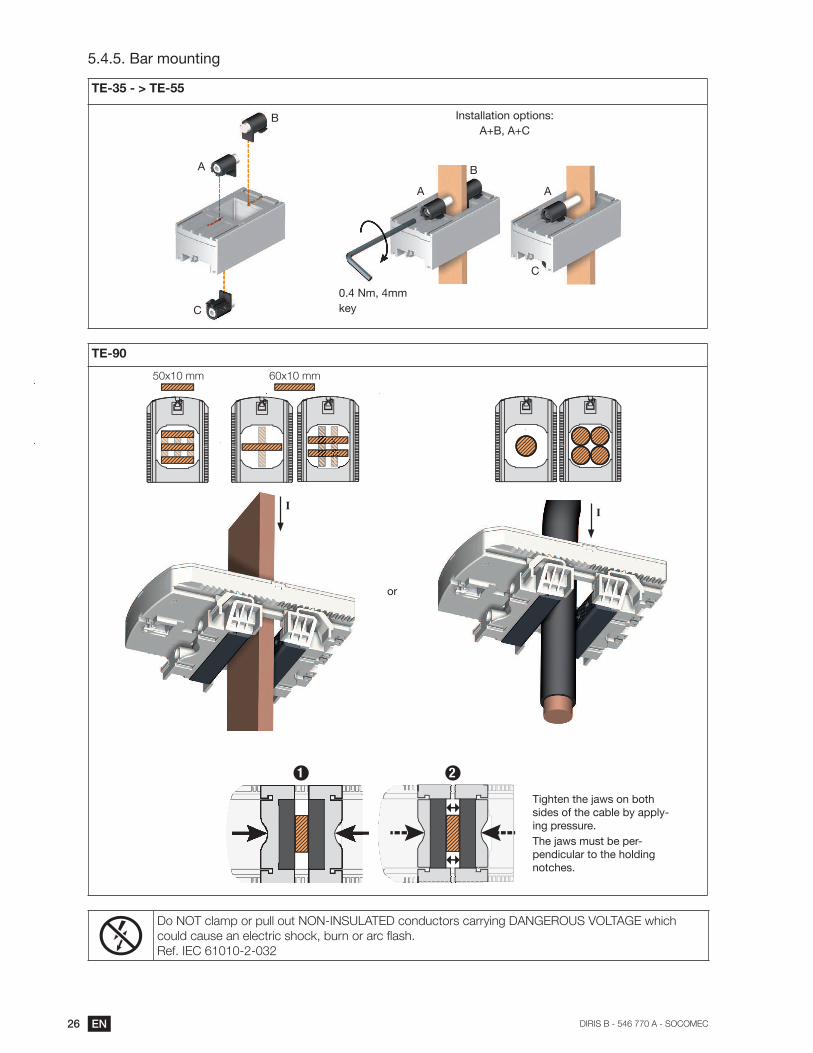
5.4.5.
TE-35 - > TE-55
A
A A
C
Installation options:
key
C
TE-90
or
Tighten the jaws on both
sides of the cable by apply-
ing pressure.
The jaws must be per-
pendicular to the holding
notches.
II
21
Do NOT clamp or pull out NON-INSULATED conductors carrying DANGEROUS VOLTAGE which
Ref. IEC 61010-2-032

27ENDIRIS B 546 770 A - SOCOMEC
5.4.6. Sensors assembly
TE-18 TE-25 - > TE-55 TE-35 - > TE-55
1.4236
Staggered assembly
2x
Linear mounting
1x
Staggered assembly
Mounting accessories for sensor combination:
Reference Linear assembly Staggered assembly
4829 0598 x30
These accessories must be ordered separately.
5.4.7. Sealing accessories for sensors
21
Reference Sealing case for terminal
4829 0600 x20
These accessories must be ordered separately.

28 EN DIRIS B - 546 770 A - SOCOMEC
5.5. Installing TR split-core sensors
5.5.1. Cable mounting
1
Click!
4
k!
433
2
K
L
III
LL
I
cables only!
Do NOT clamp or pull out NON-INSULATED conductors carrying DANGEROUS VOLTAGE which
Ref. IEC 61010-2-032
5.6. stranded sensors TE mounting
5.6.1. Installing the casing
DIN rail Plate Chassis
1.38 35
0.29 or 0.597.5 or 15
1
2
Washer
max.
0.195
3.9
41
00

29ENDIRIS B 546 770 A - SOCOMEC
5.6.2. Cable mounting
Click!
=
=
=
=
Centred position for the best measurement Do NOT clamp or pull out
NON-INSULATED conductors
carrying DANGEROUS
VOLTAGE which could cause an
Ref. IEC 61010-2-032
5.6.3.
=
=
=
=
Centred position for the best measurement
Click!
Do NOT clamp or pull out
NON-INSULATED conductors
carrying DANGEROUS
VOLTAGE which could cause
Ref. IEC 61010-2-032
5.7. Installing the 5A adapter
4
3
1
25A secondary current transformer
Do NOT clamp or pull out NON-INSULATED conductors carrying DANGEROUS VOLTAGE which
Ref. IEC 61010-2-032

30 EN DIRIS B - 546 770 A - SOCOMEC
6. CONNECTION
6.1. Connecting the DIRIS B
4x current sensor
inputs (**)RS485
(ref. 4829 0000 / 4829 0010)
7 mm
solid 0.14 mm2 -> 1.5 mm2
stranded 0.14 mm2 -> 1.5 mm2solstrand
2 digital inputs
7 mm
solid 0.14 mm2 -> 1.5 mm2
stranded 0.14 mm2 -> 1.5 mm2
2 di
Optional modules
- Inputs/Outputs:
O-iod
O-ioa
O-it
- Communication:
O-m
O-p
O-b/ip
O-b/mstp
Voltage inputs Display
DIRIS D-30
Auxiliary power
supply110-230 Vac
USB
Type B micro USB
10 mm
0.2 mm2 -> 2.5 mm2 solid
2 -> 1.5 mm2
2x 2 positions - spring-cage
10 mm
0.2 mm2 -> 2.5 mm2 solid
2 -> 1.5 mm2
2x 6 positions - spring-cage
Current sensor
inputs
Use a SOCOMEC cable for
accordance with IEC 61010-1 version 3.0.
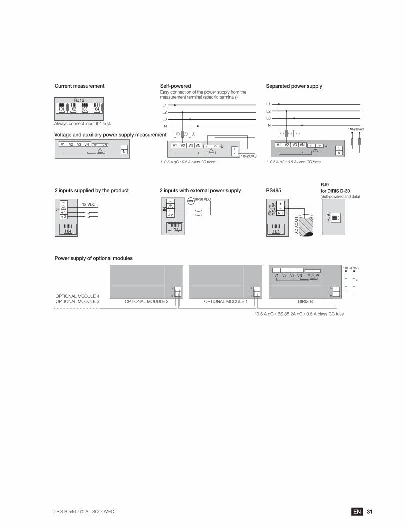
31ENDIRIS B 546 770 A - SOCOMEC
Always connect input I01 first.
Power supply of optional modules
V2 VNV3 V1VNV1
N
L
Voltage and auxiliary power supply measurement
1
2
IN
12 VDC
I 04
2 inputs supplied by the product
1
2
IN
10-30 VDC
I 04
2 inputs with external power supply
Current measurement
NCSla
ve
RS
48
5
LIY
CY-C
YI 01
RS485RJ9
for DIRIS D-30(Self-powered and data)
110-230VACN
L1
L2
L3
V2 VNV3 V1VNV1
N
L
111
Separated power supply
N
L
N
L1
L2
L3
V2 VNV3
110-230VAC
V1VNV1
111
Self-poweredEasy connection of the power supply from the measurement terminal (specific terminals)
1. 0.5 A gG / 0.5 A class CC fuses.1. 0.5 A gG / 0.5 A class CC fuses.
RJ9
RJ12
I 04I 03I 02I 01
110-230VAC
V2 VNV3 V1VNV1
N
L
N
L
N
L
*
OPTIONAL MODULE 1OPTIONAL MODULE 2OPTIONAL MODULE 3
OPTIONAL MODULE 4
DIRIS B
32 EN DIRIS B - 546 770 A - SOCOMEC
6.2. Connecting the optional modules
6.2.1. Input/output modules
7 mm
7 mm
Power supply
7 mm
0.14 mm2-> 1.5 mm2 solid0.14 mm2 -> 1.5 mm2 stranded
0.14 mm2-> 1.5 mm2 solid0.14 mm2 -> 1.5 mm2 stranded
0.2 mm2 -> 2.5 mm2 solid2 -> 1.5 mm2 stranded with ferrule
0.14 mm2 -> 1.5 mm2 solid2 -> 1.5 mm2 stranded
2x 2 positions - spring-cage0.25 Nm max.
0.
2x 2 p
10 mm
DIRIS O-iodModule with 2 digital inputs/
outputs
DIRIS O-ioaModule with 2 analogue inputs/outputs
DIRIS O-itModule with 3
temperature inputs
7 mm
0.14 mm2-> 1.5 mm2 solid 0.14 mm2 -> 1.5 mm2 strandedLength max. 3 m
7 mm
0.14 mm2 -> 1.5 mm2 solid2 -> 1.5 mm2 stranded
PT100 or PT1000
INPUT
OUTPUT
DIRIS O-iod
SU
PP
LY
Power supply of optional modules
DIRIS O-iod and O-ioa
INPUT
OUTPUT
DIRIS O-ioa
IN3
DIRIS O-it
IN1 IN2
33ENDIRIS B 546 770 A - SOCOMEC
6.2.2. Communication modules
DIRIS O-mModbus RS485 communication
module
DIRIS O-pPROFIBUS DPV1 communication module
7 mm
solid 0.14 mm2 -> 1.5 mm2
stranded 0.14 mm2 -> 1.5 mm2
max. SUBD9
Power supplyPoPoPoPoPoPoPoPoPoPoPoPoPoPoPoPoPoPoPoPoPoPoPoPoPoPoPowe
10 mm
0.2 mm2 -> 2.5 mm2 solid2 -> 1.5 mm2stranded with ferrule
2x 2 positions - spring-cage
Modbus RS485 PROFIBUS
max
PROFIB
DIRIS O-b/ipBACnet/IP
communicationmodule
DIRIS O-b/mstpBACnet MS/TP communication module
7 mm
0.2 mm2-> 2.5 mm2 solid 0.2 mm2 -> 2.5 mm2 stranded
Power supplyPoPoPoPoPoPoPoPoPoPoPoPoPoPoPoPoPoPoPoPoPoPoPoPoPoPoPoPoPoPoPowe
10 mm
0.2 mm2 -> 2.5 mm2 solid2 -> 1.5 mm2stranded with ferrule
2x 2 positions - spring-cage
RJ45
BACnet/IP BACnet MS/TP
RJ4
BAC
DIRIS O-m RS485
SUBD 9
DIRIS O-p
ETH
DIRIS O-b/ip DIRIS O-b/mstp

34 EN DIRIS B - 546 770 A - SOCOMEC
6.3. Connecting the current sensors
6.3.1. Connection concept
DIRIS B
TE / TR / TF current sensors
Recommendations:
- It is recommended that current sensors are installed in the same direction.
6.3.2. Details of the RJ12 connections for each current sensor
TE TR TF
SOCOMEC cable for
current sensors
Click!
PMD
DIRIS B
DIRIS Digiware
TE-18 to TE-55
TE-90
SOCOMEC cable for current sensors
Do not bring into contact with dangerous voltages
PMD
DIRIS B
DIRIS Digiware
Click!
SOCOMEC cable for
current sensors
Cover sealing
Click!
SOCcab
current s
Cove
cur
1
3
2
PMD
DIRIS B
DIRIS Digiware
35ENDIRIS B 546 770 A - SOCOMEC
6.3.3. Connecting to the electrical network and loads
simultaneously.
SOCOMEC cables must be used for the current sensors.
6.3.3.1.
installation.
Network type Configurable load
1P+N
2P
2P+N
3P*
3P+N
6.3.3.2. Description of the main network and load combinations
Legend:
3P+N – 4CT
I
I01 I02 I03 I04
N
V1 V2 V3 VN
V
(1)
L1
L2
L3
3 + N Three phase load
Current sensor (CT)
Current terminal BVoltage terminal B
network with 4 current sensors
CTCurrent sensor
3
Balanced load
3
Unbalanced load
36 EN DIRIS B - 546 770 A - SOCOMEC
Three-phase + Neutral
3P+N – 4CT
Three-phase + Neutral
3P+N – 3CT & 3P – 1CT
I
I01 I02 I03 I04
N
V1 V2 V3 VN
V
(1)
L1
L2
L3
3 + N
N
V1 V2 V3 VN
V
(1)
I
L1
L2
L3
3
I01 I02 I03 I04
3 + N
Three-phase + Neutral
3P+N – 3CT & 1P+N – 1CT
Three-phase
3P – 3CT & 3P – 1CT
balanced load)
1
N
V1 V2 V3 VN
V
(1)
I
L1
L2
L3
I01 I02 I03 I04
3 + N
V1 V2 V3 VN
V I
L1
L2
L3
3
I01 I02 I03 I04
3
Three-phase
3P – 2CT (x2) Three-phase
3P – 1CT (x4)
(4 three-phase balanced loads)
V1 V2 V3 VN
V I
L1
L2
L3
I01 I02 I03 I04
3 3
V1 V2 V3 VN
V I
L1
L2
L3
3333
I01 I02 I03 I04
Fuse: 0.5 A gG / BS 88 2A gG / 0.5 A class CC
37ENDIRIS B 546 770 A - SOCOMEC
Two-phase + Neutral
2P+N – 2CT (x2)
(2 two-phase loads)
Two-phase
2P – 1CT (x4)
(4 two-phase loads)
(1)
V1 V2 V3 VN
V I
L1
L2
N
I01 I02 I03 I04
2 + N2 + N
I
V1 V2 V3 VN
V
L1
L2
I01 I02 I03 I04
2222
Single-phase
1P+N – 1CT (x4)
(4 single-phase loads)
V I
V1 V2 V3 VN
L1
N
I02 I03I01 I04
(1)
1 1 1 1
0.5 A gG / BS 88 2A gG / 0.5 A class CC fuse
Fuse: 0.5 A gG / BS 88 2A gG / 0.5 A class CC
Notes relating to connections:
The
and associated network voltages.
3P – 2CT
3P – 1CT: this connection requires a three-phase network that is perfectly balanced.
6.3.4. Connection of the functional earth
It is recommended that the functional earth is connected to guarantee optimum measuring accuracy and better
emissivity/immunity for the electromagnetic compatibility (class B in conducted emission). Earth must not be used
in a neutral IT system.
38 EN DIRIS B - 546 770 A - SOCOMEC
7. STATUS AND AUTO-ADDRESSING LEDS
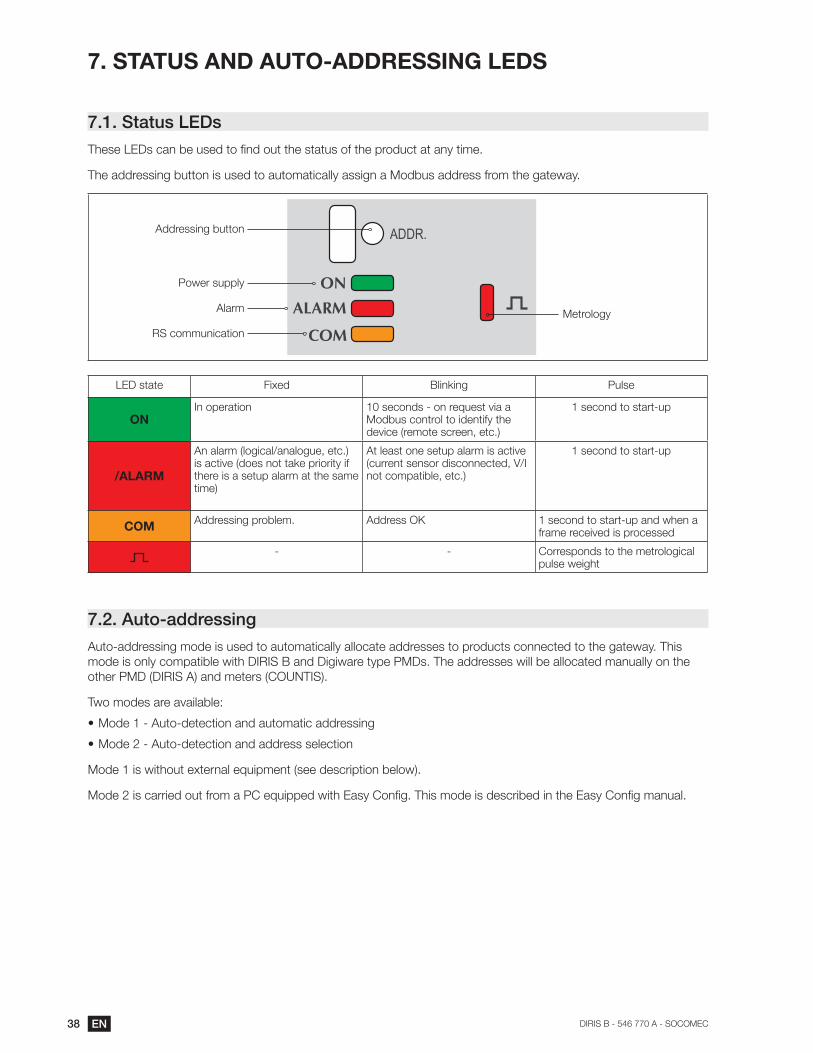
7.1. Status LEDs
The addressing button is used to automatically assign a Modbus address from the gateway.
Power supply
Addressing button
AlarmMetrology
RS communication
LED state Fixed Blinking Pulse
ONIn operation 10 seconds - on request via a
Modbus control to identify the 1 second to start-up
/ALARMis active (does not take priority if there is a setup alarm at the same time)
At least one setup alarm is active 1 second to start-up
COMAddressing problem. Address OK 1 second to start-up and when a
frame received is processed
- - Corresponds to the metrological pulse weight
7.2. Auto-addressing
Auto-addressing mode is used to automatically allocate addresses to products connected to the gateway. This
mode is only compatible with DIRIS B and Digiware type PMDs. The addresses will be allocated manually on the
other PMD (DIRIS A) and meters (COUNTIS).
Two modes are available:
Mode 1 - Auto-detection and automatic addressing
Mode 2 - Auto-detection and address selection
Mode 1 is without external equipment (see description below).
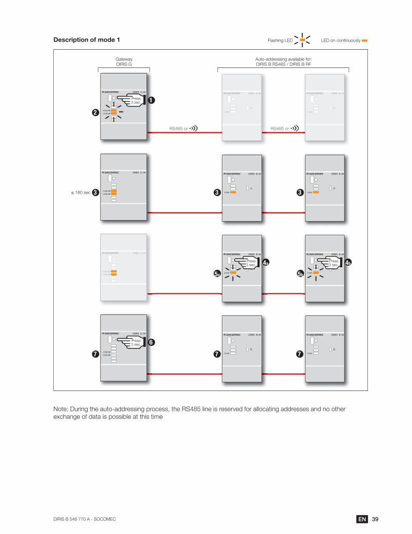
39ENDIRIS B 546 770 A - SOCOMEC
Description of mode 1 Flashing LED LED on continuously
Auto-addressing available for: DIRIS B RS485 / DIRIS B RF
GatewayDIRIS G
RS485 or RS485 or
Press 3 sec.
Press 3 sec.
Press 3 sec. 1
Press 3 sec. 6
4a 4b
2
7 7 7
5a 5b
33 3
exchange of data is possible at this time
40 EN DIRIS B - 546 770 A - SOCOMEC
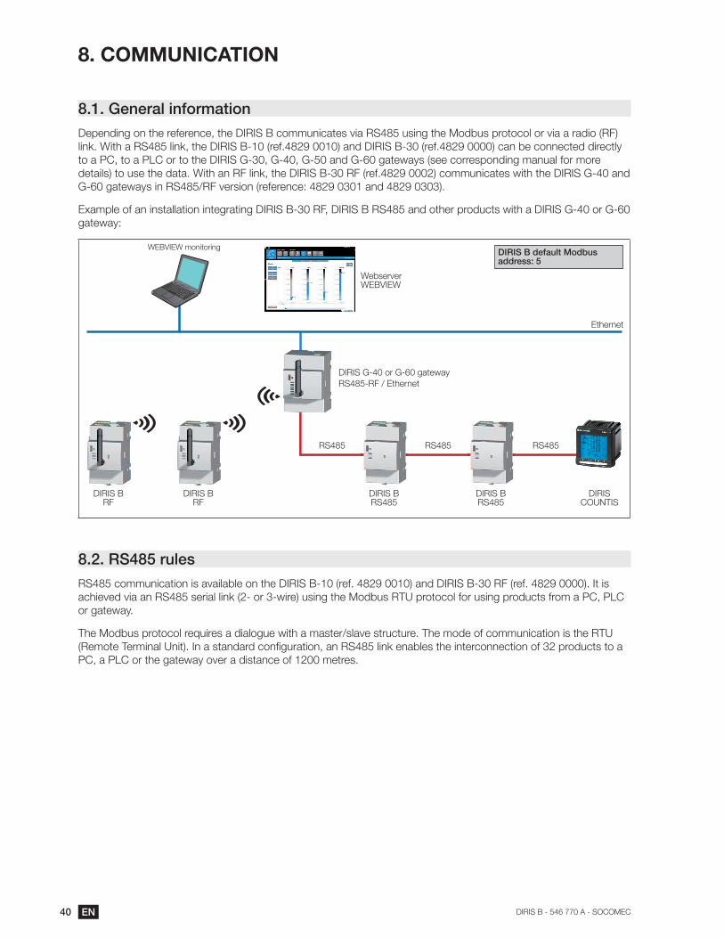
8. COMMUNICATION
8.1. General information
G-60 gateways in RS485/RF version (reference: 4829 0301 and 4829 0303).
gateway:
RF
RF
address: 5
RS485 RS485RS485
Ethernet
RS485RS485DIRIS
COUNTIS
DIRIS G-40 or G-60 gateway
RS485-RF / Ethernet
WebserverWEBVIEW
WEBVIEW monitoring
8.2. RS485 rules
RS485 communication is available on the DIRIS B-10 (ref. 4829 0010) and DIRIS B-30 RF (ref. 4829 0000). It is
or gateway.
The Modbus protocol requires a dialogue with a master/slave structure. The mode of communication is the RTU
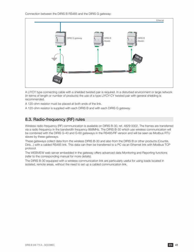
41ENDIRIS B 546 770 A - SOCOMEC
RS485 RS485
DIRIS G gateway
Ethernet
A LIYCY type connecting cable with a shielded twisted pair is required. In a disturbed environment or large network
(in terms of length or number of products) the use of a type LIYCY-CY twisted pair with general shielding is
recommended.
A 120-ohm resistor must be placed at both ends of the link.
8.3. Radio-frequency (RF) rules
be combined with the DIRIS G-40 and G-60 gateways in the RS485/RF version and will be seen as Modbus RTU
slaves by these gateways.
protocol.
The WEBVIEW web server embedded in the gateway offers advanced data Monitoring and Reporting functions
(refer to the corresponding manual for more details).
42 EN DIRIS B - 546 770 A - SOCOMEC
RS485
Gateway
RS485-RF / Ethernet
RF
Ethernet
RF RF RF
8.3.1.
Only use antennae recommended by SOCOMEC.
The table below describes the permitted occupancy rate based on the selected frequency and the resulting
maximum number of DIRIS B-30 RF which can be connected.
Channel no. Frequency (MHz) Permitted occupancy rate Maximum number of DIRIS B-30 RF
connected
420 868.1000 16
436 868.3000 16
452 868.5000 16
472 868.7500 3
488 868.9500 3
504 869.1500 3
869.5250 32
539 869.5875 32
According to EN300 220: radiated radio and REC7003 emissions: use of the RF 868 MHz bandwidth.
8.3.2. EC Declaration of ConformityThe EC Declaration of Conformity for the DIRIS B
is available here:
www.socomec.com/en/diris-b
8.4. Communication tablesThe communication tables and associated explanations can
be found on the documentations page for the DIRIS B on the
SOCOMEC website at the following address:
www.socomec.com/en/diris-b
The communication tables are sent via Modbus.
43ENDIRIS B 546 770 A - SOCOMEC
9. CONFIGURATION
before using the USB connection.
Ethernet or USB.
9.1.
9.1.1. Connection modes
RS485
USB cable for
Easy
PC
USB
RS485 RS485 RS485
DIRIS Digiware C-31DIRIS G
DIRIS
COUNTISRS485
DIRIS B
Easy
PC
USB
Easy
PC
USB
DIRIS Digiware D-50 / D-70
RS485
RS485
DIRIS BDIRIS
COUNTIS
44 EN DIRIS B - 546 770 A - SOCOMEC
RS485 RS485 RS485
DIRIS Digiware C-31DIRIS G
DIRIS
COUNTISRS485
DIRIS B
Ethernet
Easy
PC
Ethernet
Easy
PC
DIRIS Digiware D-50 / D-70
RS485
RS485
DIRIS BDIRIS
COUNTIS
45ENDIRIS B 546 770 A - SOCOMEC
9.1.2.
successive steps:
Network —> Loads —> Measurement method —> Values to be stored —> Alarms —>
(1)
(2)
For each setting selected (1) (2).
transformer is used.
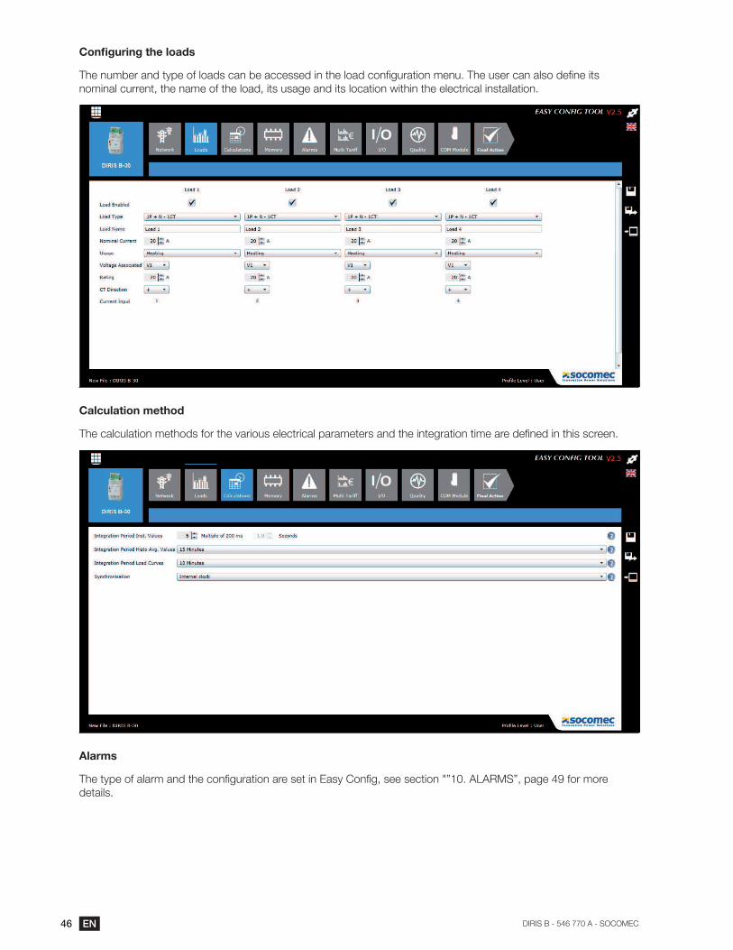
46 EN DIRIS B - 546 770 A - SOCOMEC
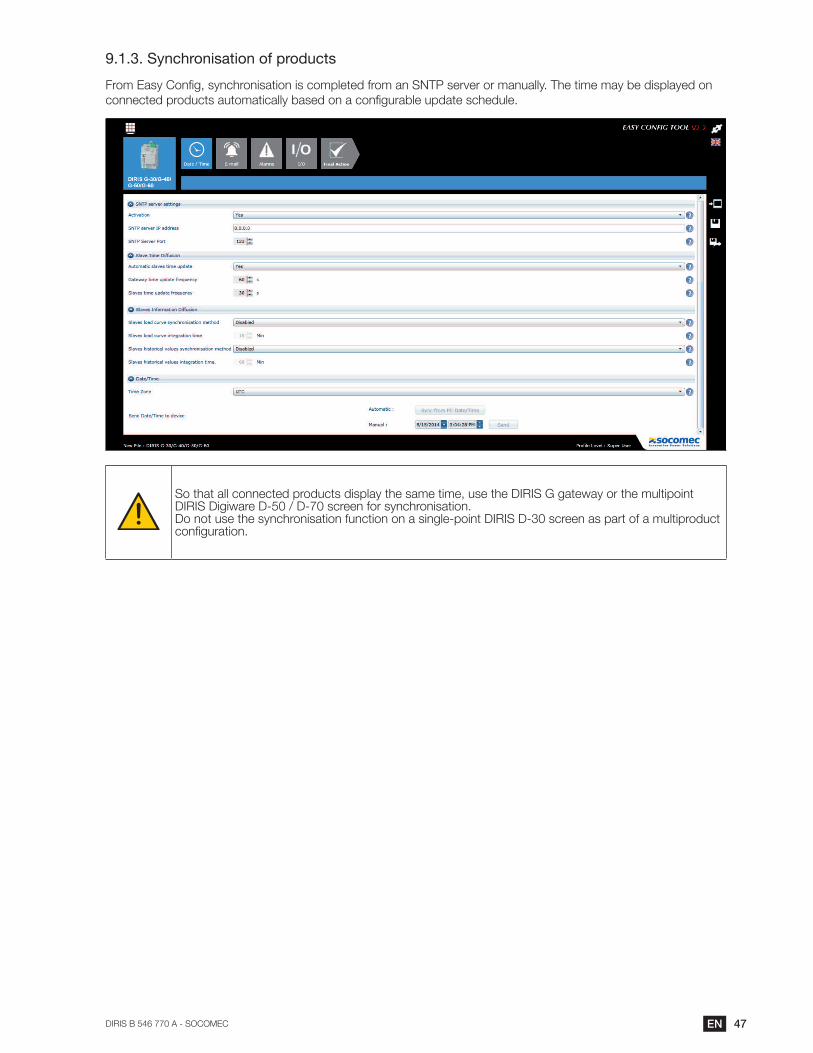
Calculation method
Alarms
details.
47ENDIRIS B 546 770 A - SOCOMEC
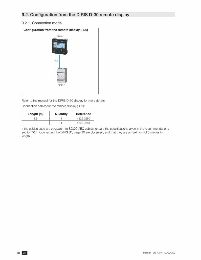
9.1.3. Synchronisation of products
48 EN DIRIS B - 546 770 A - SOCOMEC
9.2.
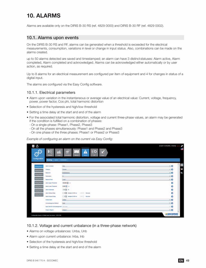
9.2.1. Connection mode
RJ9
Display
Refer to the manual for the DIRIS D-30 display for more details.
Connection cables for the remote display (RJ9):
Length (m) Quantity Reference
1.5 1 4829 0280
3 1 4829 0281
length.
49ENDIRIS B 546 770 A - SOCOMEC
10. ALARMS
Alarms are available only on the DIRIS B-30 RS (ref. 4829 0000) and DIRIS B-30 RF (ref. 4829 0002).
10.1. Alarms upon events
alarms created.
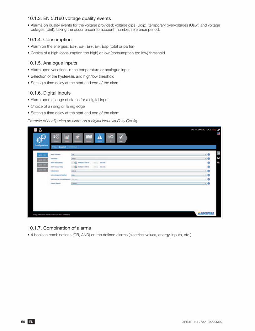
digital input.
10.1.1. Electrical parameters
Selection of the hysteresis and high/low threshold
Setting a time delay at the start and end of the alarm
-
- On all the phases simultaneously: Phase1 and Phase2 and Phase3
- On one phase of the three phases: Phase1 or Phase2 or Phase3
10.1.2. Voltage and current unbalance (in a three-phase network)
Selection of the hysteresis and high/low threshold
Setting a time delay at the start and end of the alarm
50 EN DIRIS B - 546 770 A - SOCOMEC
10.1.3. EN 50160 voltage quality events
10.1.4. Consumption
Choice of a high (consumption too high) or low (consumption too low) threshold
10.1.5. Analogue inputs
Alarm upon variations in the temperature or analogue input
Selection of the hysteresis and high/low threshold
Setting a time delay at the start and end of the alarm
10.1.6. Digital inputs
Alarm upon change of status for a digital input
Choice of a rising or falling edge
Setting a time delay at the start and end of the alarm
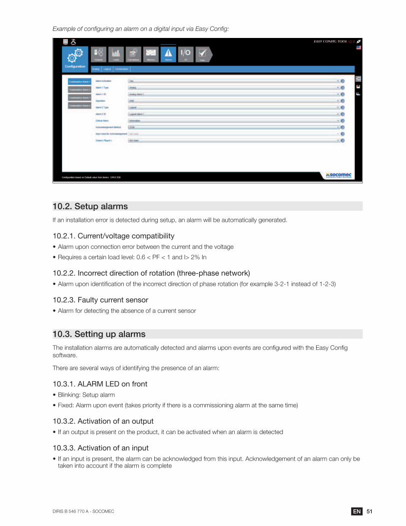
10.1.7. Combination of alarms
51ENDIRIS B 546 770 A - SOCOMEC
10.2. Setup alarms
10.2.1. Current/voltage compatibility
Alarm upon connection error between the current and the voltage
10.2.2. Incorrect direction of rotation (three-phase network)
10.2.3. Faulty current sensor
Alarm for detecting the absence of a current sensor
10.3. Setting up alarms
software.
There are several ways of identifying the presence of an alarm:
10.3.1. ALARM LED on front
Blinking: Setup alarm
Fixed: Alarm upon event (takes priority if there is a commissioning alarm at the same time)
10.3.2. Activation of an output
10.3.3. Activation of an input
taken into account if the alarm is complete

52 EN DIRIS B - 546 770 A - SOCOMEC
10.3.4. RS485 Modbus
Information on the alarms with timestamping available via the RS485 communication bus
Sends alarm acknowledgement
10.3.5.
Information on the alarms with timestamping
Sends alarm acknowledgement
53ENDIRIS B 546 770 A - SOCOMEC
11. FEATURES
11.1. DIRIS B features
11.1.1. Mechanical features
Casing type DIN-rail mounting module and base
Casing protection index IP20 / IK06
Index of protection of front side IP40 on the nose in modular assembly / IK08
Sealing for the voltage and current connections
WeightDIRIS B-10: 160 g DIRIS B-30 RS: 160 g DIRIS B-30 RF: 175 g
11.1.2.
Auxiliary power supply
Alternative voltage
Frequency 50/60 Hz
Power consumption
Connection
11.1.3. Input characteristics
Input
Number 2
Type / Power supply
Input function
Connection
11.1.4. Measuring characteristics
Measurement accuracy
Accuracy According to IEC 61557-12PMD DD classification in
Measuring energy and power
Active energy and active power accuracy 0.2 DIRIS B class only Class 0.5 with TE or TF sensors Class 1 with TR sensors
Accuracy of reactive energy
Power factor measurement
Accuracy Class 0.5 with TE or TF sensors Class 1 with TR sensors
Voltage measurement
Characteristics of the network measured
Frequency range 45 - 65Hz
Frequency accuracy Class 0.02
Network type Single-phase/ Two-phase / Two-phase with neutral / Three-phase / Three-phase with neutral
54 EN DIRIS B - 546 770 A - SOCOMEC
Measurement by voltage transformer Primary: 400 000 VAC
Input consumption
Permanent overload
Accuracy of voltage measurement Class 0.2
Connection
Measurement of currents
Number of current inputs 4
Associated current sensors
Accuracy 0.2 DIRIS B class only Class 0.5 with TE or TF sensorsClass 1 with TR sensors
Connection Specific Socomec cable with RJ12 connectors
11.1.5.
DIRIS B-30 RS485
Connection RS485
Connection type 2 - 3 half duplex wires
Protocol Modbus RTU
Baudrate 1200 - 115200 bauds
Function
Connection
DIRIS B-30 RF
Connection Wireless radio-frequency
Frequency range
Baudrate 38400 bauds
Function
USB
Connection USB 2
Protocol Modbus RTU on USB
Function
Connection Type B micro USB connector
11.1.6.
Operating temperature
Storage temperature
Operating humidity
Operating altitude
Vibration
Rated impulse voltage IEC 60947-1 V. IMP: 6.4kV
PEP ecopassport - ISO 14025
Impact resistance Front panel: 5J - casing: 1J (IEC 61010-1 Ed 3.0)
55ENDIRIS B 546 770 A - SOCOMEC
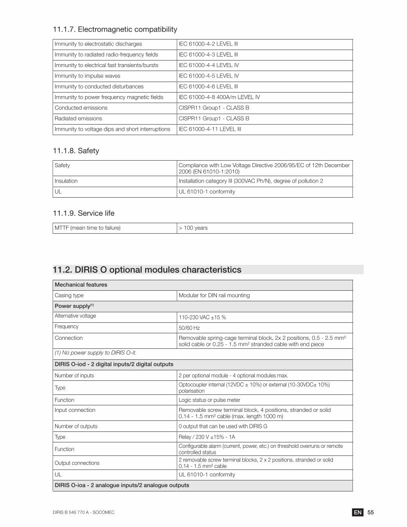
11.1.7. Electromagnetic compatibility
Immunity to electrostatic discharges IEC 61000-4-2 LEVEL III
Immunity to radiated radio-frequency fields IEC 61000-4-3 LEVEL III
Immunity to electrical fast transients/bursts IEC 61000-4-4 LEVEL IV
Immunity to impulse waves IEC 61000-4-5 LEVEL IV
Immunity to conducted disturbances IEC 61000-4-6 LEVEL III
Immunity to power frequency magnetic fields IEC 61000-4-8 400A/m LEVEL IV
Conducted emissions CISPR11 Group1 - CLASS B
Radiated emissions CISPR11 Group1 - CLASS B
Immunity to voltage dips and short interruptions IEC 61000-4-11 LEVEL III
11.1.8. Safety
Safety Compliance with Low Voltage Directive 2006/95/EC of 12th December 2006 (EN 61010-1:2010)
Insulation
UL UL 61010-1 conformity
11.1.9. Service life
MTTF (mean time to failure) > 100 years
11.2. DIRIS O optional modules characteristics
Mechanical features
Casing type Modular for DIN rail mounting
Power supply(1)
Alternative voltage
Frequency 50/60 Hz
Connection
(1) No power supply to DIRIS O-it.
DIRIS O-iod - 2 digital inputs/2 digital outputs
Number of inputs 2 per optional module - 4 optional modules max.
Typepolarisation
Function Logic status or pulse meter
Input connection
Number of outputs
Type
Functioncontrolled status
Output connections
UL UL 61010-1 conformity
DIRIS O-ioa - 2 analogue inputs/2 analogue outputs
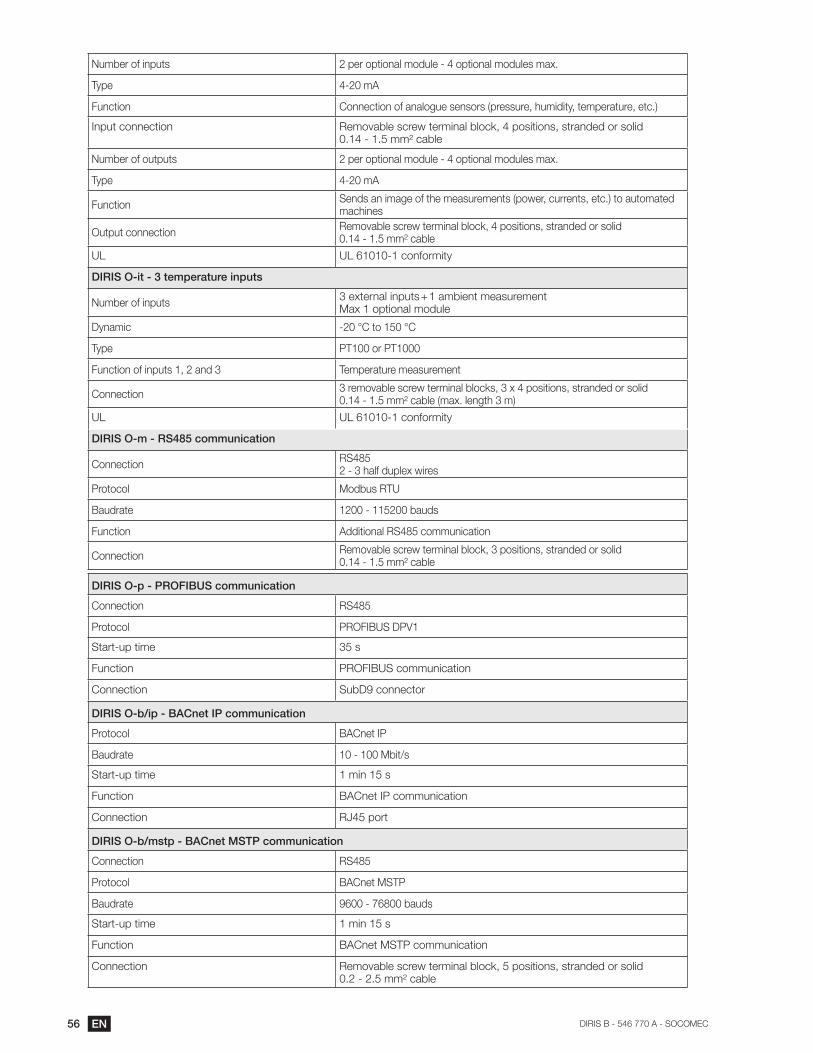
56 EN DIRIS B - 546 770 A - SOCOMEC
Number of inputs 2 per optional module - 4 optional modules max.
Type 4-20 mA
Function
Input connection
Number of outputs 2 per optional module - 4 optional modules max.
Type 4-20 mA
Functionmachines
Output connection
UL UL 61010-1 conformity
DIRIS O-it - 3 temperature inputs
Number of inputsMax 1 optional module
Dynamic
Type PT100 or PT1000
Temperature measurement
Connection
UL UL 61010-1 conformity
DIRIS O-m - RS485 communication
ConnectionRS4852 - 3 half duplex wires
Protocol Modbus RTU
Baudrate 1200 - 115200 bauds
Function Additional RS485 communication
Connection
DIRIS O-p - PROFIBUS communication
Connection RS485
Protocol PROFIBUS DPV1
Start-up time 35 s
Function PROFIBUS communication
Connection SubD9 connector
DIRIS O-b/ip - BACnet IP communication
Protocol BACnet IP
Baudrate 10 - 100 Mbit/s
Start-up time 1 min 15 s
Function BACnet IP communication
Connection RJ45 port
DIRIS O-b/mstp - BACnet MSTP communication
Connection RS485
Protocol BACnet MSTP
Baudrate 9600 - 76800 bauds
Start-up time 1 min 15 s
Function BACnet MSTP communication
Connection
57ENDIRIS B 546 770 A - SOCOMEC
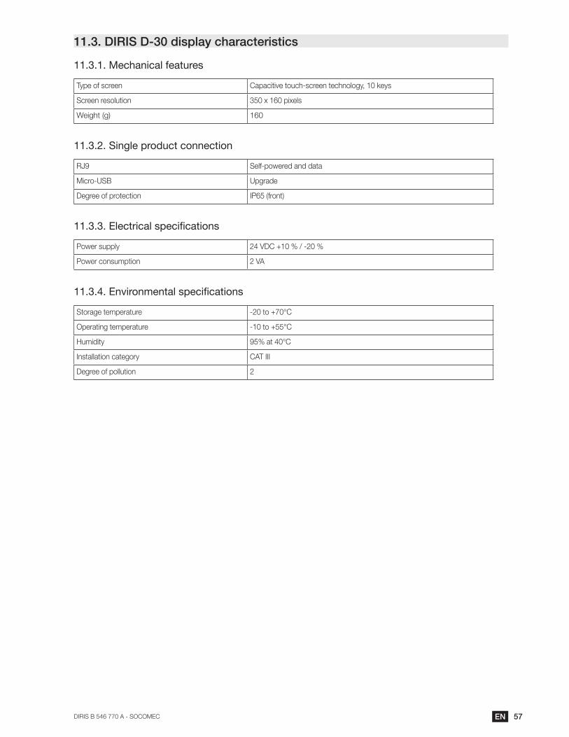
11.3. DIRIS D-30 display characteristics
11.3.1. Mechanical features
Type of screen
Screen resolution 350 x 160 pixels
Weight (g) 160
11.3.2. Single product connection
RJ9 Self-powered and data
Micro-USB Upgrade
Degree of protection IP65 (front)
11.3.3.
Power supply
Power consumption 2 VA
11.3.4.
Storage temperature
Operating temperature
Humidity
Installation category CAT III
Degree of pollution 2
58 EN DIRIS B - 546 770 A - SOCOMEC
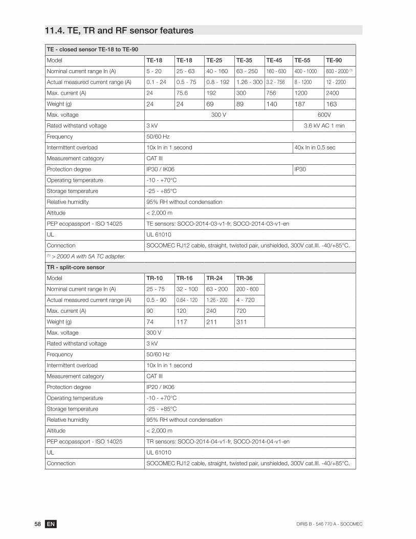
11.4. TE, TR and RF sensor features
TE - closed sensor TE-18 to TE-90
Model TE-18 TE-18 TE-25 TE-35 TE-45 TE-55 TE-90
Nominal current range In (A) 5 - 20 25 - 63 40 - 160 63 - 250 160 - 630 400 - 1000 600 - 2000 (1)
Actual measured current range (A) 0.1 - 24 0.5 - 75 0.8 - 192 1.26 - 300 3.2 - 756 8 - 1200 12 - 2200
Max. current (A) 24 75.6 192 300 756 1200 2400
Weight (g) 24 24 69 89 140 187 163
Max. voltage 600V
Rated withstand voltage
Frequency 50/60 Hz
Intermittent overload 10x In in 1 second
Measurement category CAT III
Protection degree IP30 / IK06 IP30
Operating temperature
Storage temperature
Relative humidity
Altitude
PEP ecopassport - ISO 14025
UL
Connection
(1)
TR - split-core sensor
Model TR-10 TR-16 TR-24 TR-36
Nominal current range In (A) 25 - 75 32 - 100 63 - 200 200 - 600
Actual measured current range (A) 0.5 - 90 0.64 - 120 1.26 - 200 4 - 720
Max. current (A) 90 120 240 720
Weight (g) 74 117 211 311
Max. voltage
Rated withstand voltage
Frequency 50/60 Hz
Intermittent overload 10x In in 1 second
Measurement category CAT III
Protection degree IP20 / IK06
Operating temperature
Storage temperature
Relative humidity
Altitude
PEP ecopassport - ISO 14025
UL
Connection
59ENDIRIS B 546 770 A - SOCOMEC
TF - Flexible current sensor
Model TF-55 TF-120 TF-300
Nominal current range In (A) 150 - 600 500 - 2000 1600 - 6000
Actual measured current range (A) 3 - 720 10 - 2400 32 - 7200
Weight (g) 114 142 220
Max. voltage
Rated withstand voltage
Frequency
Intermittent overload 10x In in 1 second
Measurement category CAT III
Protection degree IP30 / IK07
Operating temperature
Storage temperature
Relative humidity
Altitude
UL
Connection

60 EN DIRIS B - 546 770 A - SOCOMEC
12. PERFORMANCE CLASSES
Performance classes are drawn up in compliance with IEC 61557-12 version 1 (08/2007)
Temperature K55
Overall operating performance class for active power or active energy
0.5 in combination with TE or TF solid-core sensors 1 in combination with TR split-core sensors
12.1.
Symbol Function
Overall operating
+ associated sensors* (TE, TR, TF) in compliance with IEC 61557-12
Measurement range
Pa Total active power0.5 with TE or TF sensors1 with TR sensors
A V
SA V
0.5 with TE or TF sensors1 with TR sensors
Ea Total active energy0.5 with TE or TF sensors1 with TR sensors
ErA V
EapA V
0.5 with TE or TF sensors1 with TR sensors
f Frequency 0.02
0.2 DIRIS B only0.5 with TE or TF sensors1 with TR sensors
INc Calculated neutral current 1 with TE or TF sensors2 with TR sensors
U Voltage (Lp-Lg or Lp-N) 0.2
PFA V
0.5 with TE or TF sensors1 with TR sensors
0.5 lagging to 0.8 leading
- -
Udip Voltage dip (Lp-Lg or Lp-N) 0.5 -
Uswl Temporary overvoltages (Lp-Lg or Lp-N) 0.5 -
Uint Voltage outage (Lp-Lg or Lp-N) 0.2 -
Unba Voltage amplitude unbalance (Lp-N) 0.5 -
Unb Voltage phase and amplitude unbalance (Lp-Lg or Lp-N)
0.2 -
THD-RuTotal harmonic distortion rate of the voltage (relative 1 Orders 1 to 63
Uh Voltage harmonics 1 -
THD-RiTotal harmonic distortion rate of the current (relative Orders 1 to 63
Ih Current harmonics -
Msv Centralised remote control signals - -
61ENDIRIS B 546 770 A - SOCOMEC
12.2. Evaluation of the power supply quality
Symbol Function
Overall operating
+ associated sensors (TE, TR, TF) in compliance with IEC 61557-12
Measurement range
f Frequency 0.02
0.2 DIRIS B only 0.5 with TE or TF sensors1 with TRsensors
INc Calculated neutral current 1 with TE or TF sensors2 with TRsensors
U Voltage (Lp-Lg or Lp-N) 0.2 50 - 300 VAC Ph/N
- -
Udip Voltage dip (Lp-Lg or Lp-N) 0.5 -
Uswl Temporary overvoltages (Lp-Lg or Lp-N) 0.5 -
Uint Voltage outage (Lp-Lg or Lp-N) 0.2 -
Unba Voltage amplitude unbalance (Lp-N) 0.5 -
Unb Voltage phase and amplitude unbalance (Lp-Lg or Lp-N)
0.2 -
Uh Voltage harmonics 1 -
Ih Current harmonics -
Msv Centralised remote control signals - -

62 EN DIRIS B - 546 770 A - SOCOMEC

63ENDIRIS B 546 770 A - SOCOMEC

546 770 A - EN - 01/17
CORPORATE HQ CONTACT:
SOCOMEC SAS
1-4 RUE DE WESTHOUSE
67235 BENFELD, FRANCE
http://www.socomec.com


