32
Ferdinand Schad KG Steigstraße 25-27 D-78600 Kolbingen Telephone +49 (0) 74 63 - 980 - 0 Fax +49 (0) 74 63 - 980 - 200 [email protected] www.schako.de Ceiling induction diffuser DISA-360
Ferdinand Schad KGSteigstraße 25-27
D-78600 KolbingenTelephone +49 (0) 74 63 - 980 - 0
Fax +49 (0) 74 63 - 980 - [email protected]
Ceiling induction diffuserDISA-360
Contents
Construction subject to change. No return possible!
Ceiling induction diffuser DISA-360
11/29 - 2 20.10.2015Version:
Description ........................................................................................................................................3Advantages ........................................................................................................................................3Function ............................................................................................................................................3Description of the equipment ...................................................................................................................4
Construction .............................................................................................................................................................................. 4Model ......................................................................................................................................................................................... 4Accessories ................................................................................................................................................................................ 4Fastening ................................................................................................................................................................................... 4
Models and dimensions .........................................................................................................................5Dimensions and weights ............................................................................................................................................................ 5Accessories ................................................................................................................................................................................ 7Figures ....................................................................................................................................................................................... 7
Technical data ....................................................................................................................................8Performance data ....................................................................................................................................................................... 8Sound level .............................................................................................................................................................................. 16Flow data ................................................................................................................................................................................. 17
Control units ..................................................................................................................................... 25Valves ...................................................................................................................................................................................... 25Actuators ................................................................................................................................................................................. 27Control units ............................................................................................................................................................................ 28Condensation monitor ............................................................................................................................................................. 30
Assembly ........................................................................................................................................ 31Maintenance .................................................................................................................................... 31Legend ........................................................................................................................................... 31Order details .................................................................................................................................... 32Specification text ............................................................................................................................... 33
Ceiling induction diffuser DISA-360
DescriptionThe ceiling induction diffuser DISA-360 is based on air/watertechnology and works by the energy-efficient induction princi-ple. Its four-way throw of the cooled and heated air fulfills max-imum performance and comfort requirements. The constructionis very maintenance-friendly and is also suitable for low falseceiling heights, due to its small height. 4 different nozzle config-urations B, C, D, E and two sizes 600 x 600 and 600 x 1200 allowthe DISA-360 to be adjusted to almost any performance require-ments and grid ceiling sizes.
Advantages
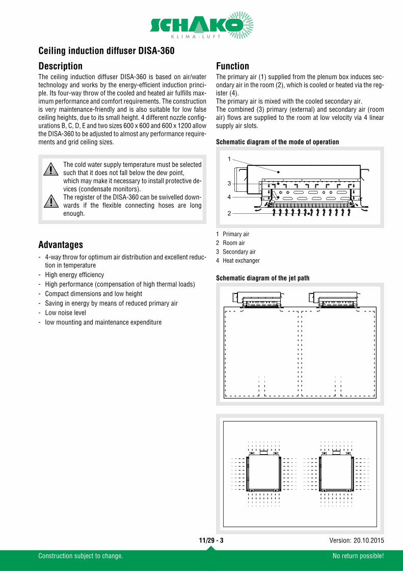
FunctionThe primary air (1) supplied from the plenum box induces sec-ondary air in the room (2), which is cooled or heated via the reg-ister (4).The primary air is mixed with the cooled secondary air.The combined (3) primary (external) and secondary air (roomair) flows are supplied to the room at low velocity via 4 linearsupply air slots.
Schematic diagram of the mode of operation
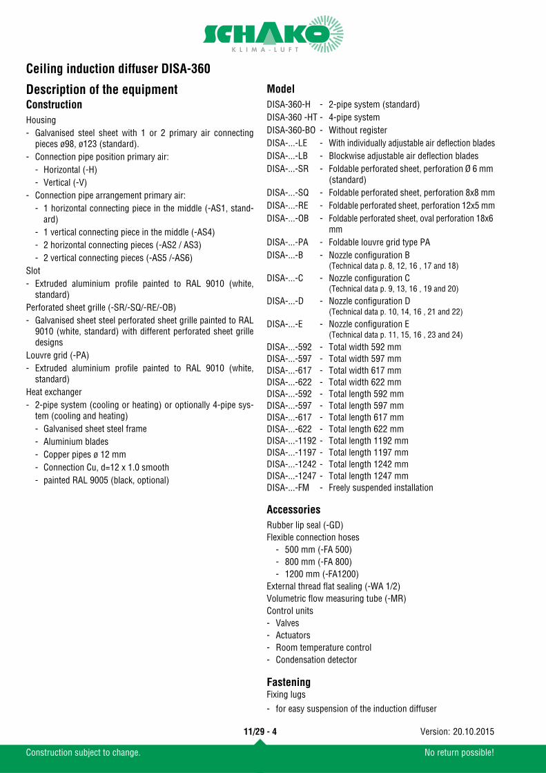
Schematic diagram of the jet path
- 4-way throw for optimum air distribution and excellent reduc-tion in temperature
- High energy efficiency- High performance (compensation of high thermal loads)- Compact dimensions and low height- Saving in energy by means of reduced primary air- Low noise level- low mounting and maintenance expenditure
The cold water supply temperature must be selectedsuch that it does not fall below the dew point, which may make it necessary to install protective de-vices (condensate monitors).The register of the DISA-360 can be swivelled down-wards if the flexible connecting hoses are longenough.
1 Primary air2 Room air3 Secondary air4 Heat exchanger
1
3
4
2
11/29 - 3
Construction subject to change. No return possible!
20.10.2015Version:
Ceiling induction diffuser DISA-360
Description of the equipmentConstruction
Model
Accessories
FasteningFixing lugs
Housing- Galvanised steel sheet with 1 or 2 primary air connecting
pieces ø98, ø123 (standard). - Connection pipe position primary air:
- Horizontal (-H)- Vertical (-V)
- Connection pipe arrangement primary air:- 1 horizontal connecting piece in the middle (-AS1, stand-
ard)- 1 vertical connecting piece in the middle (-AS4) - 2 horizontal connecting pieces (-AS2 / AS3) - 2 vertical connecting pieces (-AS5 /-AS6)
Slot- Extruded aluminium profile painted to RAL 9010 (white,
standard)Perforated sheet grille (-SR/-SQ/-RE/-OB)- Galvanised sheet steel perforated sheet grille painted to RAL
9010 (white, standard) with different perforated sheet grilledesigns
Louvre grid (-PA)- Extruded aluminium profile painted to RAL 9010 (white,
standard)Heat exchanger- 2-pipe system (cooling or heating) or optionally 4-pipe sys-
tem (cooling and heating)- Galvanised sheet steel frame- Aluminium blades- Copper pipes ø 12 mm- Connection Cu, d=12 x 1.0 smooth- painted RAL 9005 (black, optional)
DISA-360-H - 2-pipe system (standard)DISA-360 -HT - 4-pipe systemDISA-360-BO - Without registerDISA-...-LE - With individually adjustable air deflection bladesDISA-...-LB - Blockwise adjustable air deflection bladesDISA-...-SR - Foldable perforated sheet, perforation Ø 6 mm
(standard)DISA-...-SQ - Foldable perforated sheet, perforation 8x8 mmDISA-...-RE - Foldable perforated sheet, perforation 12x5 mmDISA-...-OB - Foldable perforated sheet, oval perforation 18x6
mmDISA-...-PA - Foldable louvre grid type PADISA-...-B - Nozzle configuration B
(Technical data p. 8, 12, 16 , 17 and 18)
DISA-...-C - Nozzle configuration C(Technical data p. 9, 13, 16 , 19 and 20)
DISA-...-D - Nozzle configuration D(Technical data p. 10, 14, 16 , 21 and 22)
DISA-...-E - Nozzle configuration E(Technical data p. 11, 15, 16 , 23 and 24)
DISA-...-592 - Total width 592 mmDISA-...-597 - Total width 597 mmDISA-...-617 - Total width 617 mmDISA-...-622 - Total width 622 mmDISA-...-592 - Total length 592 mmDISA-...-597 - Total length 597 mmDISA-...-617 - Total length 617 mmDISA-...-622 - Total length 622 mmDISA-...-1192 - Total length 1192 mmDISA-...-1197 - Total length 1197 mmDISA-...-1242 - Total length 1242 mmDISA-...-1247 - Total length 1247 mmDISA-...-FM - Freely suspended installation
Rubber lip seal (-GD)Flexible connection hoses
- 500 mm (-FA 500)- 800 mm (-FA 800)- 1200 mm (-FA1200)
External thread flat sealing (-WA 1/2)Volumetric flow measuring tube (-MR)Control units- Valves- Actuators- Room temperature control- Condensation detector
- for easy suspension of the induction diffuser
11/29 - 4
Construction subject to change. No return possible!
20.10.2015Version:
Ceiling induction diffuser DISA-360
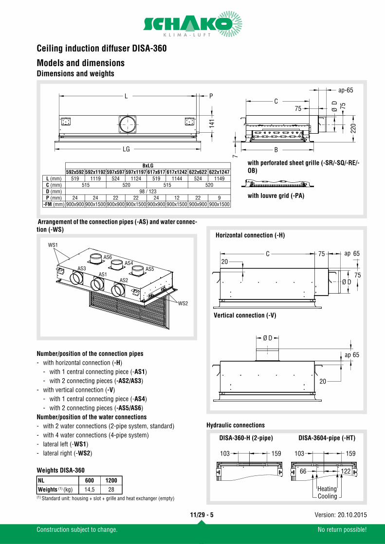
Models and dimensionsDimensions and weights
Arrangement of the connection pipes (-AS) and water connec-tion (-WS)
Weights DISA-360
(1) Standard unit: housing + slot + grille and heat exchanger (empty)
Hydraulic connections
LG
141
B
7
C
Ø D
220
75
L P
75
65
with perforated sheet grille (-SR/-SQ/-RE/-OB)
with louvre grid (-PA)
BxLG592x592 592x1192 597x597 597x1197 617x617 617x1242 622x622 622x1247
L (mm) 519 1119 524 1124 519 1144 524 1149C (mm) 515 520 515 520D (mm) 98 / 123P (mm) 24 24 22 22 24 12 22 9
-FM (mm) 900x900 900x1500 900x900 900x1500 900x900 900x1500 900x900 900x1500
ap-
Number/position of the connection pipes- with horizontal connection (-H)
- with 1 central connecting piece (-AS1)- with 2 connecting pieces (-AS2/AS3)
- with vertical connection (-V)- with 1 central connecting piece (-AS4)- with 2 connecting pieces (-AS5/AS6)
Number/position of the water connections- with 2 water connections (2-pipe system, standard)- with 4 water connections (4-pipe system)- lateral left (-WS1)- lateral right (-WS2)
NL 600 1200
Weights (1) (kg) 14,5 28
AS3
AS2
WS1
WS2
AS1
AS6
AS5AS4
75Ø D
6575C20
Ø D
65
20
Horizontal connection (-H)
Vertical connection (-V)
ap
ap
159103103 159
66 122
Heating Cooling
DISA-360-H (2-pipe) DISA-3604-pipe (-HT)
11/29 - 5
Construction subject to change. No return possible!
20.10.2015Version:
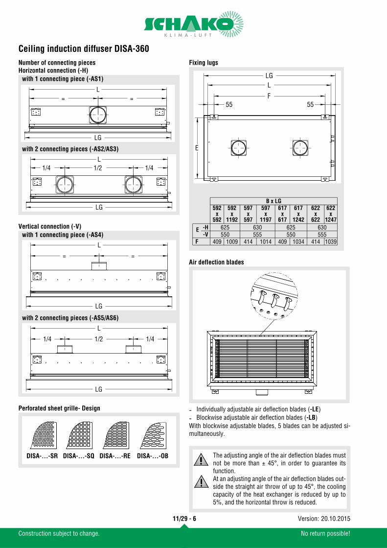
Ceiling induction diffuser DISA-360
Number of connecting piecesHorizontal connection (-H)Vertical connection (-V)
Perforated sheet grille- Design
Fixing lugs
Air deflection blades
With blockwise adjustable blades, 5 blades can be adjusted si-multaneously.
1/2 1/4L
LG
1/4
= =L
LG
with 1 connecting piece (-AS1)
with 2 connecting pieces (-AS2/AS3)
=
L
LG
=
with 1 connecting piece (-AS4)
with 2 connecting pieces (-AS5/AS6)
1/2 1/4
L
LG
1/4
DISA-...-SR DISA-...-SQ DISA-...-RE DISA-...-OB
- Individually adjustable air deflection blades (-LE)- Blockwise adjustable air deflection blades (-LB)
LLG
55 55
E
F
B x LG592
x592
592x
1192
597x
597
597x
1197
617x
617
617x
1242
622x
622
622x
1247
E -H 625 630 625 630-V 550 555 550 555
F 409 1009 414 1014 409 1034 414 1039
The adjusting angle of the air deflection blades mustnot be more than ± 45°, in order to guarantee itsfunction.At an adjusting angle of the air deflection blades out-side the straight air throw of up to 45°, the coolingcapacity of the heat exchanger is reduced by up to5%, and the horizontal throw is reduced.
11/29 - 6
Construction subject to change. No return possible!
20.10.2015Version:
Ceiling induction diffuser DISA-360
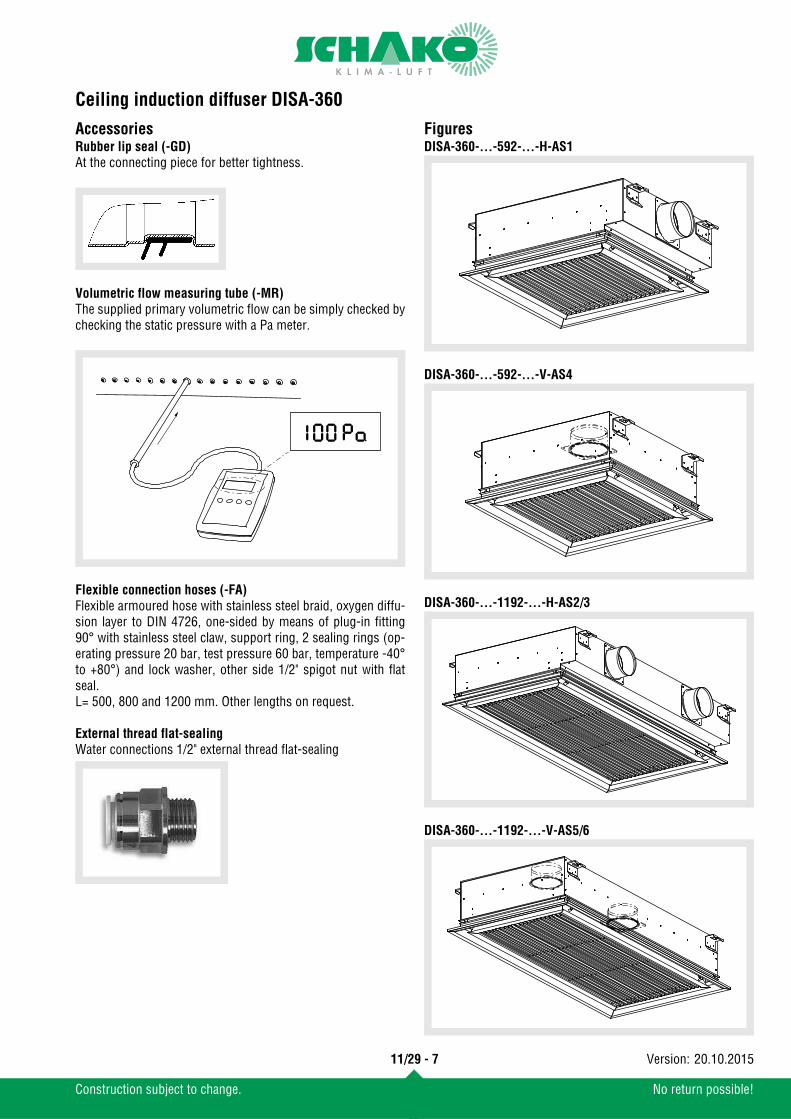
AccessoriesRubber lip seal (-GD)At the connecting piece for better tightness.
Volumetric flow measuring tube (-MR)The supplied primary volumetric flow can be simply checked bychecking the static pressure with a Pa meter.
Flexible connection hoses (-FA)Flexible armoured hose with stainless steel braid, oxygen diffu-sion layer to DIN 4726, one-sided by means of plug-in fitting90° with stainless steel claw, support ring, 2 sealing rings (op-erating pressure 20 bar, test pressure 60 bar, temperature -40°to +80°) and lock washer, other side 1/2" spigot nut with flatseal.L= 500, 800 and 1200 mm. Other lengths on request.
External thread flat-sealingWater connections 1/2" external thread flat-sealing
FiguresDISA-360-...-592-...-H-AS1
DISA-360-...-592-...-V-AS4
DISA-360-...-1192-...-H-AS2/3
DISA-360-...-1192-...-V-AS5/6
11/29 - 7
Construction subject to change. No return possible!
20.10.2015Version:
Ceiling induction diffuser DISA-360
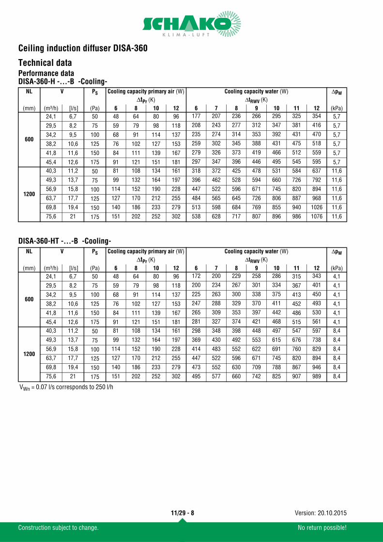
Technical dataPerformance dataDISA-360-H -...-B -Cooling-
DISA-360-HT -...-B -Cooling-
NL V PS Cooling capacity primary air (W) Cooling capacity water (W) ΔpWΔtPr (K) ΔtRWV (K)
(mm) (m³/h) [l/s] (Pa) 6 8 10 12 6 7 8 9 10 11 12 (kPa)
600
24,1 6,7 50 48 64 80 96 177 207 236 266 295 325 354 5,7
29,5 8,2 75 59 79 98 118 208 243 277 312 347 381 416 5,7
34,2 9,5 100 68 91 114 137 235 274 314 353 392 431 470 5,7
38,2 10,6 125 76 102 127 153 259 302 345 388 431 475 518 5,7
41,8 11,6 150 84 111 139 167 279 326 373 419 466 512 559 5,7
45,4 12,6 175 91 121 151 181 297 347 396 446 495 545 595 5,7
1200
40,3 11,2 50 81 108 134 161 318 372 425 478 531 584 637 11,6
49,3 13,7 75 99 132 164 197 396 462 528 594 660 726 792 11,6
56,9 15,8 100 114 152 190 228 447 522 596 671 745 820 894 11,6
63,7 17,7 125 127 170 212 255 484 565 645 726 806 887 968 11,6
69,8 19,4 150 140 186 233 279 513 598 684 769 855 940 1026 11,6
75,6 21 175 151 202 252 302 538 628 717 807 896 986 1076 11,6
NL V PS Cooling capacity primary air (W) Cooling capacity water (W) ΔpW
ΔtPr (K) ΔtRWV (K)(mm) (m³/h) [l/s] (Pa) 6 8 10 12 6 7 8 9 10 11 12 (kPa)
600
24,1 6,7 50 48 64 80 96 172 200 229 258 286 315 343 4,1
29,5 8,2 75 59 79 98 118 200 234 267 301 334 367 401 4,1
34,2 9,5 100 68 91 114 137 225 263 300 338 375 413 450 4,1
38,2 10,6 125 76 102 127 153 247 288 329 370 411 452 493 4,1
41,8 11,6 150 84 111 139 167 265 309 353 397 442 486 530 4,1
45,4 12,6 175 91 121 151 181 281 327 374 421 468 515 561 4,1
1200
40,3 11,2 50 81 108 134 161 298 348 398 448 497 547 597 8,4
49,3 13,7 75 99 132 164 197 369 430 492 553 615 676 738 8,4
56,9 15,8 100 114 152 190 228 414 483 552 622 691 760 829 8,4
63,7 17,7 125 127 170 212 255 447 522 596 671 745 820 894 8,4
69,8 19,4 150 140 186 233 279 473 552 630 709 788 867 946 8,4
75,6 21 175 151 202 252 302 495 577 660 742 825 907 989 8,4
VWn = 0.07 l/s corresponds to 250 l/h
11/29 - 8
Construction subject to change. No return possible!
20.10.2015Version:

Ceiling induction diffuser DISA-360
DISA-360-H -...-C -Cooling-DISA-360-HT -...-C -Cooling-
NL V PS Cooling capacity primary air (W) Cooling capacity water (W) ΔpW ΔtPr (K) ΔtRWV (K)
(mm) (m³/h) [l/s] (Pa) 6 8 10 12 6 7 8 9 10 11 12 (kPa)
600
44,6 12,4 50 89 119 149 179 212 247 282 318 353 388 424 5,754,7 15,2 75 109 146 182 219 256 298 341 383 426 468 511 5,763 17,5 100 126 168 210 252 287 335 383 431 479 526 574 5,7
70,6 19,6 125 141 188 235 282 311 363 415 466 518 570 622 5,777 21,4 150 154 205 257 308 329 384 439 494 548 603 658 5,7
83,2 23,1 175 166 222 277 333 343 400 457 514 571 628 686 5,7
1200
74,2 20,6 50 148 198 247 297 368 430 491 553 614 675 737 11,6
91,1 25,3 75 182 243 304 364 477 556 636 715 795 874 954 11,6
105,1 29,2 100 210 280 350 420 538 628 718 808 897 987 1077 11,6
117,4 32,6 125 235 313 391 469 575 671 767 863 959 1055 1151 11,6
128,5 35,7 150 257 343 428 514 599 698 798 898 998 1097 1197 11,6
139 38,6 175 278 371 463 556 614 716 819 921 1024 1126 1228 11,6
NL V PS Cooling capacity primary air (W) Cooling capacity water (W) ΔpW ΔtPr (K) ΔtRWV (K)
(mm) (m³/h) [l/s] (Pa) 6 8 10 12 6 7 8 9 10 11 12 (kPa)
600
44,6 12,4 50 89 119 149 179 195 228 260 293 326 358 391 4,1
54,7 15,2 75 109 146 182 219 239 278 318 358 398 438 477 4,1
63 17,5 100 126 168 210 252 268 313 357 402 447 491 536 4,1
70,6 19,6 125 141 188 235 282 289 337 385 434 482 530 578 4,1
77 21,4 150 154 205 257 308 305 355 406 457 508 558 609 4,1
83,2 23,1 175 166 222 277 333 316 369 422 474 527 580 632 4,1
1200
74,2 20,6 50 148 198 247 297 352 410 469 528 586 645 703 8,4
91,1 25,3 75 182 243 304 364 451 526 601 676 752 827 902 8,4
105,1 29,2 100 210 280 350 420 507 592 676 761 845 930 1014 8,4
117,4 32,6 125 235 313 391 469 541 631 721 811 901 991 1081 8,4
128,5 35,7 150 257 343 428 514 562 655 749 842 936 1029 1123 8,4
139 38,6 175 278 371 463 556 575 671 767 863 959 1055 1151 8,4
VWn = 0.07 l/s corresponds to 250 l/h
11/29 - 9
Construction subject to change. No return possible!
20.10.2015Version:
Ceiling induction diffuser DISA-360
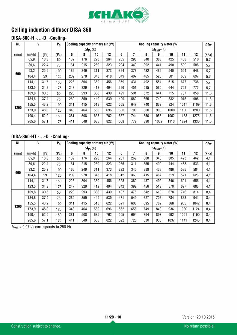
DISA-360-H -...-D -Cooling-DISA-360-HT -...-D -Cooling-
NL V PS Cooling capacity primary air (W) Cooling capacity water (W) ΔpWΔtPr (K) ΔtRWV (K)
(mm) (m³/h) [l/s] (Pa) 6 8 10 12 6 7 8 9 10 11 12 (kPa)
600
65,9 18,3 50 132 176 220 264 255 298 340 383 425 468 510 5,780,6 22,4 75 161 215 269 323 294 343 392 441 490 539 588 5,793,2 25,9 100 186 249 311 373 324 378 432 486 540 594 648 5,7104,4 29 125 209 278 348 418 349 407 465 523 581 639 697 5,7114,1 31,7 150 228 304 380 456 369 431 492 554 615 677 738 5,7123,5 34,3 175 247 329 412 494 386 451 515 580 644 708 773 5,7
1200
109,8 30,5 50 220 293 366 439 429 501 572 644 715 787 858 11,6
134,6 37,4 75 269 359 449 539 499 582 665 749 832 915 998 11,6
155,5 43,2 100 311 415 518 622 555 647 740 832 924 1017 1109 11,6
173,9 48,3 125 348 464 580 696 600 700 800 900 1000 1100 1200 11,6
190,4 52,9 150 381 508 635 762 637 744 850 956 1062 1168 1275 11,6
205,6 57,1 175 411 548 685 822 668 779 890 1002 1113 1224 1336 11,6
NL V PS Cooling capacity primary air (W) Cooling capacity water (W) ΔpWΔtPr (K) ΔtRWV (K)
(mm) (m³/h) [l/s] (Pa) 6 8 10 12 6 7 8 9 10 11 12 (kPa)
600
65,9 18,3 50 132 176 220 264 231 269 308 346 385 423 462 4,1
80,6 22,4 75 161 215 269 323 266 311 355 400 444 488 533 4,1
93,2 25,9 100 186 249 311 373 292 340 389 438 486 535 584 4,1
104,4 29 125 209 278 348 418 312 363 415 467 519 571 623 4,1
114,1 31,7 150 228 304 380 456 328 382 437 492 546 601 656 4,1
123,5 34,3 175 247 329 412 494 342 399 456 513 570 627 683 4,1
1200
109,8 30,5 50 220 293 366 439 407 475 542 610 678 746 814 8,4
134,6 37,4 75 269 359 449 539 471 549 627 706 784 863 941 8,4
155,5 43,2 100 311 415 518 622 521 608 695 782 868 955 1042 8,4
173,9 48,3 125 348 464 580 696 562 656 749 843 936 1030 1124 8,4
190,4 52,9 150 381 508 635 762 595 694 794 893 992 1091 1190 8,4
205,6 57,1 175 411 548 685 822 622 726 830 933 1037 1141 1245 8,4
VWn = 0.07 l/s corresponds to 250 l/h
11/29 - 10
Construction subject to change. No return possible!
20.10.2015Version:
Ceiling induction diffuser DISA-360
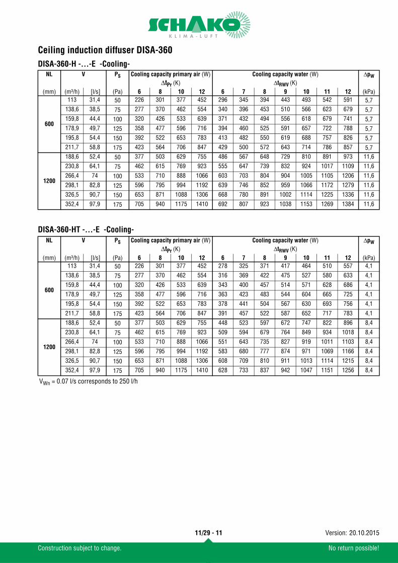
DISA-360-H -...-E -Cooling-DISA-360-HT -...-E -Cooling-
NL V PS Cooling capacity primary air (W) Cooling capacity water (W) ΔpWΔtPr (K) ΔtRWV (K)
(mm) (m³/h) [l/s] (Pa) 6 8 10 12 6 7 8 9 10 11 12 (kPa)
600
113 31,4 50 226 301 377 452 296 345 394 443 493 542 591 5,7138,6 38,5 75 277 370 462 554 340 396 453 510 566 623 679 5,7159,8 44,4 100 320 426 533 639 371 432 494 556 618 679 741 5,7178,9 49,7 125 358 477 596 716 394 460 525 591 657 722 788 5,7195,8 54,4 150 392 522 653 783 413 482 550 619 688 757 826 5,7211,7 58,8 175 423 564 706 847 429 500 572 643 714 786 857 5,7
1200
188,6 52,4 50 377 503 629 755 486 567 648 729 810 891 973 11,6
230,8 64,1 75 462 615 769 923 555 647 739 832 924 1017 1109 11,6
266,4 74 100 533 710 888 1066 603 703 804 904 1005 1105 1206 11,6
298,1 82,8 125 596 795 994 1192 639 746 852 959 1066 1172 1279 11,6
326,5 90,7 150 653 871 1088 1306 668 780 891 1002 1114 1225 1336 11,6
352,4 97,9 175 705 940 1175 1410 692 807 923 1038 1153 1269 1384 11,6
NL V PS Cooling capacity primary air (W) Cooling capacity water (W) ΔpWΔtPr (K) ΔtRWV (K)
(mm) (m³/h) [l/s] (Pa) 6 8 10 12 6 7 8 9 10 11 12 (kPa)
600
113 31,4 50 226 301 377 452 278 325 371 417 464 510 557 4,1
138,6 38,5 75 277 370 462 554 316 369 422 475 527 580 633 4,1
159,8 44,4 100 320 426 533 639 343 400 457 514 571 628 686 4,1
178,9 49,7 125 358 477 596 716 363 423 483 544 604 665 725 4,1
195,8 54,4 150 392 522 653 783 378 441 504 567 630 693 756 4,1
211,7 58,8 175 423 564 706 847 391 457 522 587 652 717 783 4,1
1200
188,6 52,4 50 377 503 629 755 448 523 597 672 747 822 896 8,4
230,8 64,1 75 462 615 769 923 509 594 679 764 849 934 1018 8,4
266,4 74 100 533 710 888 1066 551 643 735 827 919 1011 1103 8,4
298,1 82,8 125 596 795 994 1192 583 680 777 874 971 1069 1166 8,4
326,5 90,7 150 653 871 1088 1306 608 709 810 911 1013 1114 1215 8,4
352,4 97,9 175 705 940 1175 1410 628 733 837 942 1047 1151 1256 8,4
VWn = 0.07 l/s corresponds to 250 l/h
11/29 - 11
Construction subject to change. No return possible!
20.10.2015Version:
Ceiling induction diffuser DISA-360
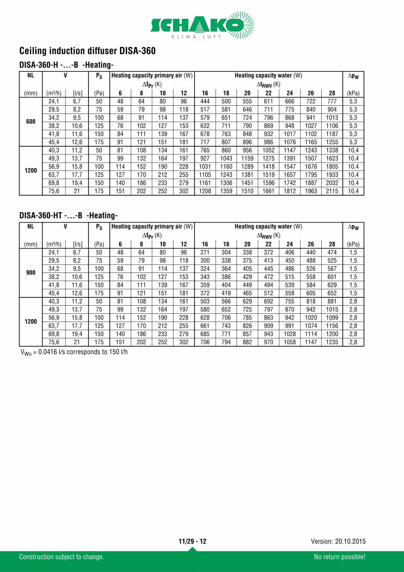
DISA-360-H -...-B -Heating-DISA-360-HT -...-B -Heating-
NL V PS Heating capacity primary air (W) Heating capacity water (W) ΔpWΔtPr (K) ΔtRWV (K)
(mm) (m³/h) [l/s] (Pa) 6 8 10 12 16 18 20 22 24 26 28 (kPa)
600
24,1 6,7 50 48 64 80 96 444 500 555 611 666 722 777 5,329,5 8,2 75 59 79 98 118 517 581 646 711 775 840 904 5,334,2 9,5 100 68 91 114 137 579 651 724 796 868 941 1013 5,338,2 10,6 125 76 102 127 153 632 711 790 869 948 1027 1106 5,341,8 11,6 150 84 111 139 167 678 763 848 932 1017 1102 1187 5,345,4 12,6 175 91 121 151 181 717 807 896 986 1076 1165 1255 5,3
1200
40,3 11,2 50 81 108 134 161 765 860 956 1052 1147 1243 1338 10,449,3 13,7 75 99 132 164 197 927 1043 1159 1275 1391 1507 1623 10,456,9 15,8 100 114 152 190 228 1031 1160 1289 1418 1547 1676 1805 10,463,7 17,7 125 127 170 212 255 1105 1243 1381 1519 1657 1795 1933 10,469,8 19,4 150 140 186 233 279 1161 1306 1451 1596 1742 1887 2032 10,475,6 21 175 151 202 252 302 1208 1359 1510 1661 1812 1963 2115 10,4
NL V PS Heating capacity primary air (W) Heating capacity water (W) ΔpWΔtPr (K) ΔtRWV (K)
(mm) (m³/h) [l/s] (Pa) 6 8 10 12 16 18 20 22 24 26 28 (kPa)
900
24,1 6,7 50 48 64 80 96 271 304 338 372 406 440 474 1,529,5 8,2 75 59 79 98 118 300 338 375 413 450 488 525 1,534,2 9,5 100 68 91 114 137 324 364 405 445 486 526 567 1,538,2 10,6 125 76 102 127 153 343 386 429 472 515 558 601 1,541,8 11,6 150 84 111 139 167 359 404 449 494 539 584 629 1,545,4 12,6 175 91 121 151 181 372 419 465 512 558 605 652 1,5
1200
40,3 11,2 50 81 108 134 161 503 566 629 692 755 818 881 2,849,3 13,7 75 99 132 164 197 580 652 725 797 870 942 1015 2,856,9 15,8 100 114 152 190 228 628 706 785 863 942 1020 1099 2,863,7 17,7 125 127 170 212 255 661 743 826 909 991 1074 1156 2,869,8 19,4 150 140 186 233 279 685 771 857 943 1028 1114 1200 2,875,6 21 175 151 202 252 302 706 794 882 970 1058 1147 1235 2,8
VWn = 0.0416 l/s corresponds to 150 l/h
11/29 - 12
Construction subject to change. No return possible!
20.10.2015Version:
Ceiling induction diffuser DISA-360
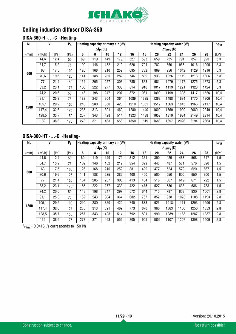
DISA-360-H -...-C -Heating-DISA-360-HT -...-C -Heating-
NL V PS Heating capacity primary air (W) Heating capacity water (W) ΔpWΔtPr (K) ΔtRWV (K)
(mm) (m³/h) [l/s] (Pa) 6 8 10 12 16 18 20 22 24 26 28 (kPa)
600
44,6 12,4 50 89 119 149 179 527 593 659 725 791 857 923 5,3
54,7 15,2 75 109 146 182 219 626 704 782 860 938 1016 1095 5,3
63 17,5 100 126 168 210 252 695 782 869 956 1042 1129 1216 5,3
70,6 19,6 125 141 188 235 282 746 839 933 1026 1119 1213 1306 5,3
77 21,4 150 154 205 257 308 785 883 981 1079 1177 1275 1373 5,3
83,2 23,1 175 166 222 277 333 814 916 1017 1119 1221 1323 1424 5,3
1200
74,2 20,6 50 148 198 247 297 872 981 1090 1199 1308 1417 1526 10,4
91,1 25,3 75 182 243 304 364 1089 1225 1362 1498 1634 1770 1906 10,4
105,1 29,2 100 210 280 350 420 1210 1361 1512 1663 1815 1966 2117 10,4
117,4 32,6 125 235 313 391 469 1280 1440 1600 1760 1920 2080 2240 10,4
128,5 35,7 150 257 343 428 514 1323 1488 1653 1819 1984 2149 2314 10,4
139 38,6 175 278 371 463 556 1350 1519 1688 1857 2026 2194 2363 10,4
NL V PS Heating capacity primary air (W) Heating capacity water (W) ΔpWΔtPr (K) ΔtRWV (K)
(mm) (m³/h) [l/s] (Pa) 6 8 10 12 16 18 20 22 24 26 28 (kPa)
600
44,6 12,4 50 89 119 149 179 312 351 390 429 468 508 547 1,5
54,7 15,2 75 109 146 182 219 354 399 443 487 531 576 620 1,5
63 17,5 100 126 168 210 252 381 429 477 524 572 620 667 1,5
70,6 19,6 125 141 188 235 282 400 450 500 550 600 650 700 1,5
77 21,4 150 154 205 257 308 413 464 516 567 619 671 722 1,5
83,2 23,1 175 166 222 277 333 422 475 527 580 633 686 738 1,5
1200
74,2 20,6 50 148 198 247 297 572 644 715 787 858 930 1001 2,8
91,1 25,3 75 182 243 304 364 682 767 852 938 1023 1108 1193 2,8
105,1 29,2 100 210 280 350 420 740 833 925 1018 1111 1203 1296 2,8
117,4 32,6 125 235 313 391 469 773 870 966 1063 1160 1256 1353 2,8
128,5 35,7 150 257 343 428 514 792 891 990 1089 1188 1287 1387 2,8
139 38,6 175 278 371 463 556 805 905 1006 1107 1207 1308 1409 2,8
VWn = 0.0416 l/s corresponds to 150 l/h
11/29 - 13
Construction subject to change. No return possible!
20.10.2015Version:
Ceiling induction diffuser DISA-360
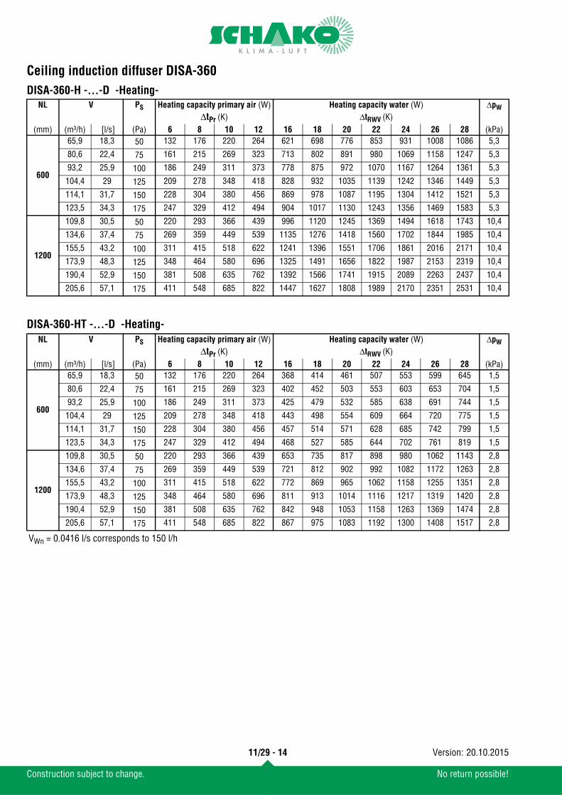
DISA-360-H -...-D -Heating-DISA-360-HT -...-D -Heating-
NL V PS Heating capacity primary air (W) Heating capacity water (W) ΔpWΔtPr (K) ΔtRWV (K)
(mm) (m³/h) [l/s] (Pa) 6 8 10 12 16 18 20 22 24 26 28 (kPa)
600
65,9 18,3 50 132 176 220 264 621 698 776 853 931 1008 1086 5,3
80,6 22,4 75 161 215 269 323 713 802 891 980 1069 1158 1247 5,3
93,2 25,9 100 186 249 311 373 778 875 972 1070 1167 1264 1361 5,3
104,4 29 125 209 278 348 418 828 932 1035 1139 1242 1346 1449 5,3
114,1 31,7 150 228 304 380 456 869 978 1087 1195 1304 1412 1521 5,3
123,5 34,3 175 247 329 412 494 904 1017 1130 1243 1356 1469 1583 5,3
1200
109,8 30,5 50 220 293 366 439 996 1120 1245 1369 1494 1618 1743 10,4
134,6 37,4 75 269 359 449 539 1135 1276 1418 1560 1702 1844 1985 10,4
155,5 43,2 100 311 415 518 622 1241 1396 1551 1706 1861 2016 2171 10,4
173,9 48,3 125 348 464 580 696 1325 1491 1656 1822 1987 2153 2319 10,4
190,4 52,9 150 381 508 635 762 1392 1566 1741 1915 2089 2263 2437 10,4
205,6 57,1 175 411 548 685 822 1447 1627 1808 1989 2170 2351 2531 10,4
NL V PS Heating capacity primary air (W) Heating capacity water (W) ΔpWΔtPr (K) ΔtRWV (K)
(mm) (m³/h) [l/s] (Pa) 6 8 10 12 16 18 20 22 24 26 28 (kPa)
600
65,9 18,3 50 132 176 220 264 368 414 461 507 553 599 645 1,5
80,6 22,4 75 161 215 269 323 402 452 503 553 603 653 704 1,5
93,2 25,9 100 186 249 311 373 425 479 532 585 638 691 744 1,5
104,4 29 125 209 278 348 418 443 498 554 609 664 720 775 1,5
114,1 31,7 150 228 304 380 456 457 514 571 628 685 742 799 1,5
123,5 34,3 175 247 329 412 494 468 527 585 644 702 761 819 1,5
1200
109,8 30,5 50 220 293 366 439 653 735 817 898 980 1062 1143 2,8
134,6 37,4 75 269 359 449 539 721 812 902 992 1082 1172 1263 2,8
155,5 43,2 100 311 415 518 622 772 869 965 1062 1158 1255 1351 2,8
173,9 48,3 125 348 464 580 696 811 913 1014 1116 1217 1319 1420 2,8
190,4 52,9 150 381 508 635 762 842 948 1053 1158 1263 1369 1474 2,8
205,6 57,1 175 411 548 685 822 867 975 1083 1192 1300 1408 1517 2,8
VWn = 0.0416 l/s corresponds to 150 l/h
11/29 - 14
Construction subject to change. No return possible!
20.10.2015Version:
Ceiling induction diffuser DISA-360
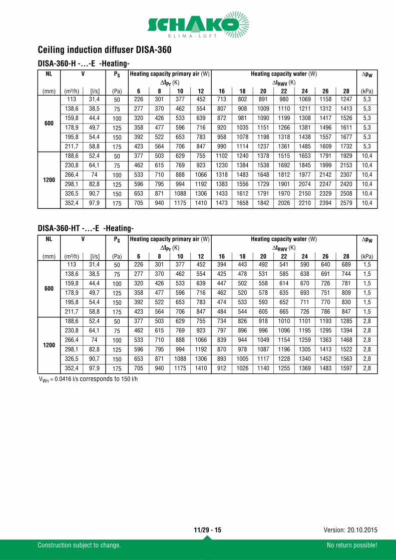
DISA-360-H -...-E -Heating-DISA-360-HT -...-E -Heating-
NL V PS Heating capacity primary air (W) Heating capacity water (W) ΔpWΔtPr (K) ΔtRWV (K)
(mm) (m³/h) [l/s] (Pa) 6 8 10 12 16 18 20 22 24 26 28 (kPa)
600
113 31,4 50 226 301 377 452 713 802 891 980 1069 1158 1247 5,3
138,6 38,5 75 277 370 462 554 807 908 1009 1110 1211 1312 1413 5,3
159,8 44,4 100 320 426 533 639 872 981 1090 1199 1308 1417 1526 5,3
178,9 49,7 125 358 477 596 716 920 1035 1151 1266 1381 1496 1611 5,3
195,8 54,4 150 392 522 653 783 958 1078 1198 1318 1438 1557 1677 5,3
211,7 58,8 175 423 564 706 847 990 1114 1237 1361 1485 1609 1732 5,3
1200
188,6 52,4 50 377 503 629 755 1102 1240 1378 1515 1653 1791 1929 10,4
230,8 64,1 75 462 615 769 923 1230 1384 1538 1692 1845 1999 2153 10,4
266,4 74 100 533 710 888 1066 1318 1483 1648 1812 1977 2142 2307 10,4
298,1 82,8 125 596 795 994 1192 1383 1556 1729 1901 2074 2247 2420 10,4
326,5 90,7 150 653 871 1088 1306 1433 1612 1791 1970 2150 2329 2508 10,4
352,4 97,9 175 705 940 1175 1410 1473 1658 1842 2026 2210 2394 2579 10,4
NL V PS Heating capacity primary air (W) Heating capacity water (W) ΔpWΔtPr (K) ΔtRWV (K)
(mm) (m³/h) [l/s] (Pa) 6 8 10 12 16 18 20 22 24 26 28 (kPa)
600
113 31,4 50 226 301 377 452 394 443 492 541 590 640 689 1,5
138,6 38,5 75 277 370 462 554 425 478 531 585 638 691 744 1,5
159,8 44,4 100 320 426 533 639 447 502 558 614 670 726 781 1,5
178,9 49,7 125 358 477 596 716 462 520 578 635 693 751 809 1,5
195,8 54,4 150 392 522 653 783 474 533 593 652 711 770 830 1,5
211,7 58,8 175 423 564 706 847 484 544 605 665 726 786 847 1,5
1200
188,6 52,4 50 377 503 629 755 734 826 918 1010 1101 1193 1285 2,8
230,8 64,1 75 462 615 769 923 797 896 996 1096 1195 1295 1394 2,8
266,4 74 100 533 710 888 1066 839 944 1049 1154 1259 1363 1468 2,8
298,1 82,8 125 596 795 994 1192 870 978 1087 1196 1305 1413 1522 2,8
326,5 90,7 150 653 871 1088 1306 893 1005 1117 1228 1340 1452 1563 2,8
352,4 97,9 175 705 940 1175 1410 912 1026 1140 1255 1369 1483 1597 2,8
VWn = 0.0416 l/s corresponds to 150 l/h
11/29 - 15
Construction subject to change. No return possible!
20.10.2015Version:
Ceiling induction diffuser DISA-360
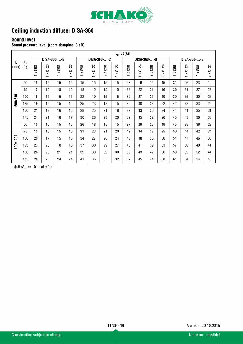
Sound levelSound pressure level (room damping -8 dB)
LP[dB (A)] <= 15 display 15
L(mm)
PS(Pa)
Lp [dB(A)]
DISA-360-…-B DISA-360-...-C DISA-360-…-D DISA-360-…-E
1 x
Ø98
1 x
Ø12
3
2 x
Ø98
2 x
Ø12
3
1 x
Ø98
1 x
Ø12
3
2 x
Ø98
2 x
Ø12
3
1 x
Ø98
1 x
Ø12
3
2 x
Ø98
2 x
Ø12
3
1 x
Ø98
1 x
Ø12
3
2 x
Ø98
2 x
Ø12
3
600x
600
50 15 15 15 15 15 15 15 15 23 16 15 15 31 26 23 19
75 15 15 15 15 18 15 15 15 28 22 21 16 36 31 27 23
100 15 15 15 15 22 19 15 15 32 27 25 19 39 35 30 26
125 19 16 15 15 25 23 18 15 35 30 28 22 42 38 33 29
150 21 19 16 15 28 25 21 18 37 33 30 24 44 41 35 31
175 24 21 18 17 30 28 23 20 39 35 32 26 45 43 36 33
600x
1200
50 15 15 15 15 26 18 15 15 37 29 26 19 45 39 36 28
75 15 15 15 15 31 23 21 20 42 34 32 25 50 44 42 34
100 20 17 15 15 34 27 26 24 45 38 36 30 54 47 46 38
125 23 20 18 18 37 30 29 27 48 41 39 33 57 50 49 41
150 26 23 21 21 39 33 32 30 50 43 42 36 59 52 52 44
175 28 25 24 24 41 35 35 32 52 45 44 38 61 54 54 46
11/29 - 16
Construction subject to change. No return possible!
20.10.2015Version:
Ceiling induction diffuser DISA-360
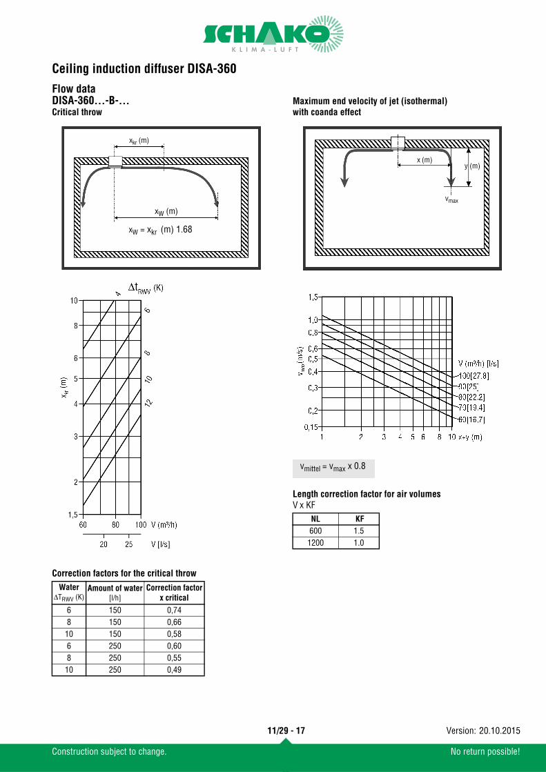
Flow dataDISA-360...-B-...Critical throw
Correction factors for the critical throw
Maximum end velocity of jet (isothermal) with coanda effect
Length correction factor for air volumesV x KF
WaterΔTRWV (K)
Amount of water[l/h]
Correction factorx critical
6 150 0,748 150 0,66
10 150 0,586 250 0,608 250 0,55
10 250 0,49
xW (m)
xW = xkr (m) 1.68
xkr (m)
NL KF600 1.5
1200 1.0
x (m)y (m)
vmax
vmittel = vmax x 0.8
11/29 - 17
Construction subject to change. No return possible!
20.10.2015Version:
Ceiling induction diffuser DISA-360
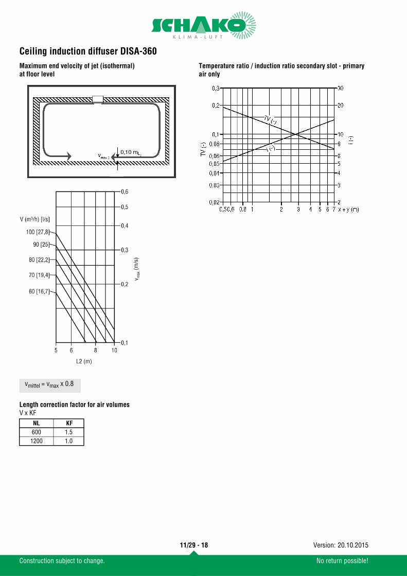
Maximum end velocity of jet (isothermal) at floor levelLength correction factor for air volumesV x KF
Temperature ratio / induction ratio secondary slot - primary air only
NL KF600 1.5
1200 1.0
vmittel = vmax x 0.8
11/29 - 18
Construction subject to change. No return possible!
20.10.2015Version:
Ceiling induction diffuser DISA-360
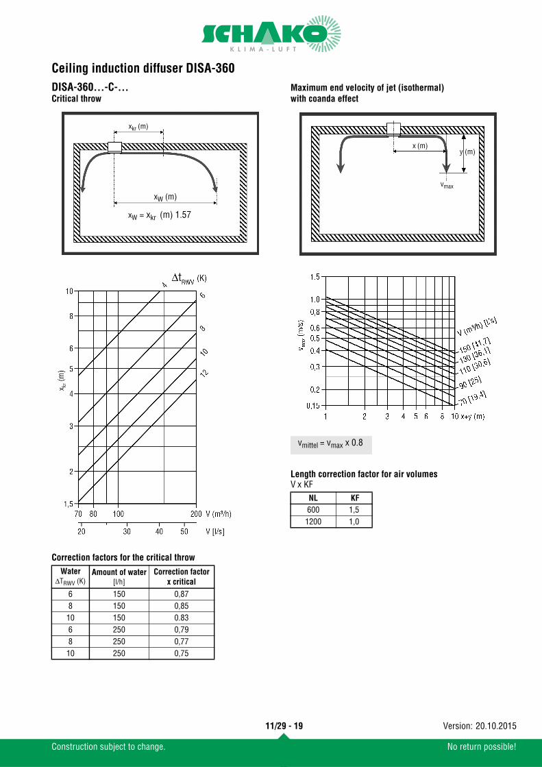
DISA-360...-C-...Critical throwCorrection factors for the critical throw
Maximum end velocity of jet (isothermal) with coanda effect
Length correction factor for air volumesV x KF
WaterΔTRWV (K)
Amount of water[l/h]
Correction factorx critical
6 150 0,878 150 0,8510 150 0.83 6 250 0,798 250 0,7710 250 0,75
xW (m)
xW = xkr (m) 1.57
xkr (m)
NL KF600 1,5
1200 1,0
x (m)y (m)
vmax
vmittel = vmax x 0.8
11/29 - 19
Construction subject to change. No return possible!
20.10.2015Version:
Ceiling induction diffuser DISA-360
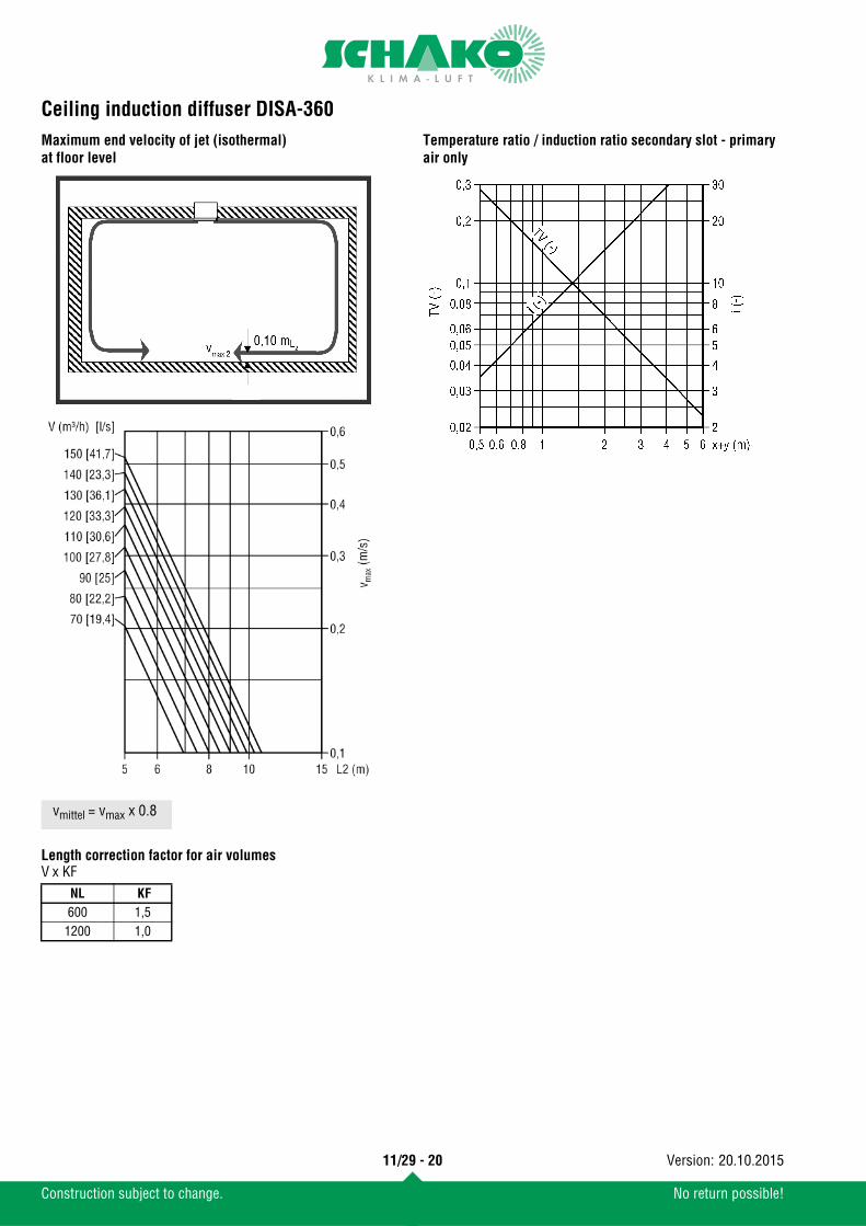
Maximum end velocity of jet (isothermal) at floor levelLength correction factor for air volumesV x KF
Temperature ratio / induction ratio secondary slot - primary air only
NL KF600 1,5
1200 1,0
vmittel = vmax x 0.8
11/29 - 20
Construction subject to change. No return possible!
20.10.2015Version:
Ceiling induction diffuser DISA-360
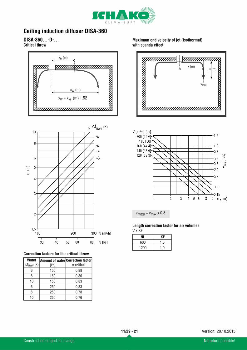
DISA-360...-D-...Critical throwCorrection factors for the critical throw
Maximum end velocity of jet (isothermal) with coanda effect
Length correction factor for air volumesV x KF
WaterΔTRWV (K)
Amount of water[l/h]
Correction factorx critical
6 150 0,888 150 0,86
10 150 0,836 250 0,838 250 0,78
10 250 0,76
xW (m)
xW = xkr (m) 1.52
xkr (m)
NL KF600 1,5
1200 1,0
x (m)y (m)
vmax
vmittel = vmax x 0.8
11/29 - 21
Construction subject to change. No return possible!
20.10.2015Version:
Ceiling induction diffuser DISA-360
Maximum end velocity of jet (isothermal) at floor levelLength correction factor for air volumesV x KF
Temperature ratio / induction ratio secondary slot - primary air only
NL KF600 1,5
1200 1,0
vmittel = vmax x 0.8
11/29 - 22
Construction subject to change. No return possible!
20.10.2015Version:
Ceiling induction diffuser DISA-360
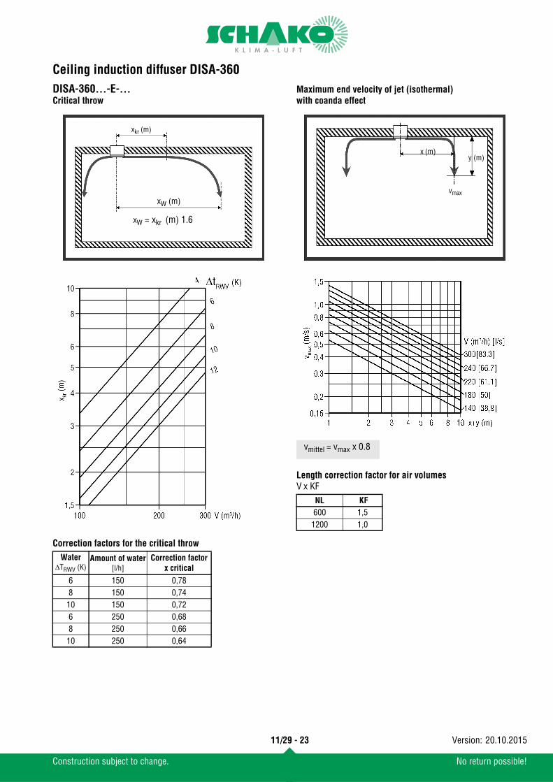
DISA-360...-E-...Critical throwCorrection factors for the critical throw
Maximum end velocity of jet (isothermal) with coanda effect
Length correction factor for air volumesV x KF
WaterΔTRWV (K)
Amount of water[l/h]
Correction factorx critical
6 150 0,788 150 0,74
10 150 0,726 250 0,688 250 0,66
10 250 0,64
xW (m)
xW = xkr (m) 1.6
xkr (m)
NL KF600 1,5
1200 1,0
x (m)y (m)
vmax
vmittel = vmax x 0.8
11/29 - 23
Construction subject to change. No return possible!
20.10.2015Version:
Ceiling induction diffuser DISA-360
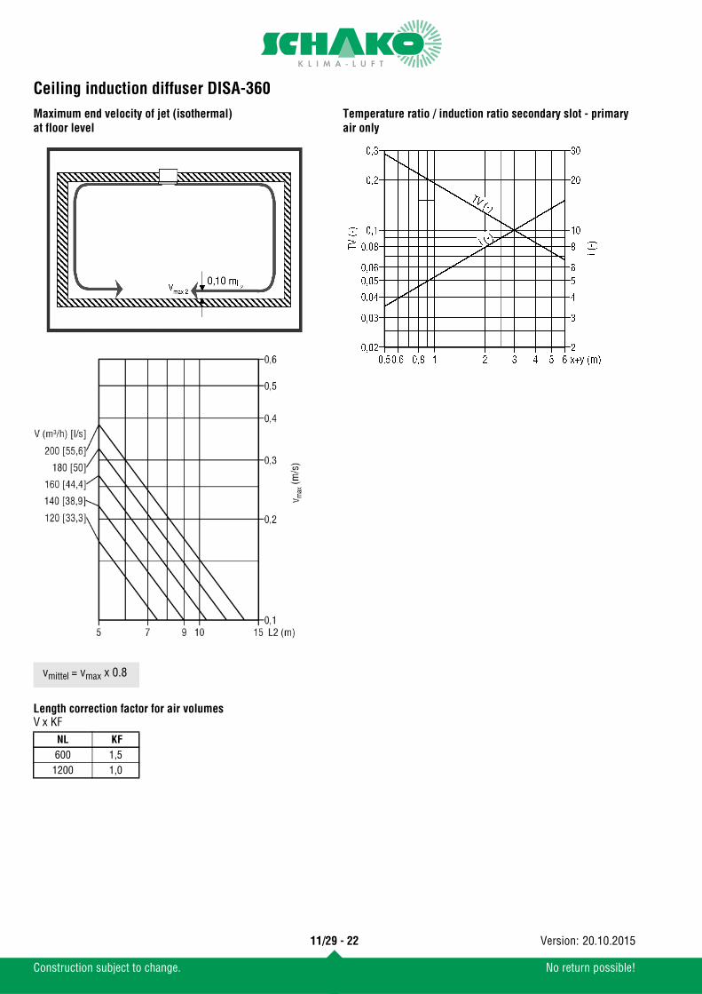
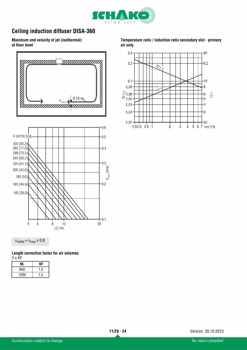
Maximum end velocity of jet (isothermal) at floor levelLength correction factor for air volumesV x KF
Temperature ratio / induction ratio secondary slot - primary air only
NL KF600 1,5
1200 1,0
vmittel = vmax x 0.8
11/29 - 24
Construction subject to change. No return possible!
20.10.2015Version:
Ceiling induction diffuser DISA-360
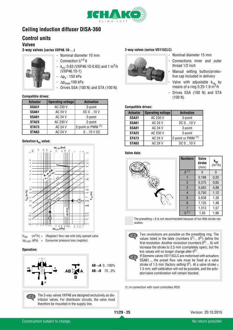
Control unitsValves3-way valves (series VXP46.10-...)
Compatible drives:
Selection kvs value:
Operation:
2-way valves (series VD115CLC)
Compatible drives:
Valve data:
(1) in connection with room controllers RDG
- Nominal diameter 10 mm- Connection G1/2 B
- kvs: 0.63 (VXP46.10-0.63) and 1 m3/h (VXP46.10-1)
- Δps : 150 kPa- Δpmax:100 kPa - Drives SSA (100 N) and STA (100 N)
Actuator Operating voltage ActivationSSA31 AC 230 V 3-pointSSA61 AC 24 V DC 0 ...10 VSSA81 AC 24 V 3-pointSTA23 AC 230 V 2-pointSTA73 AC 24 V 2-point or PWM (1)
STA63 AC 24 V 0 ...10 V DC
V100 (m3/h) = (Register) flow rate with fully opened valveΔpv100 (kPa) = Consumer pressure loss (register)
AB→A 0...100%AB→B 70...0%
The 3-way valves VXP46 are designed exclusively as dis-tributor valves. For distributor circuits, the valve musttherefore be mounted in the supply line.
- Nominal diameter 15 mm- Connections inner and outer
thread 1/2 inch- Manual setting button/protec-
tive cap included in delivery- Valve with adjustable kvs by
means of a ring 0.25-1.9 m3/h- Drives SSA (100 N) and STA
(100 N)
Actuator Operating voltage ActivationSSA31 AC 230 V 3-pointSSA61 AC 24 V DC 0 ...10 VSSA81 AC 24 V 3-pointSTA23 AC 230 V 2-pointSTA73 AC 24 V 2-point or PWM (1)
STA63 AC 24 V DC 0 ...10 V
Numbers Valve stroke(mm)
kvs (m3/h)
0 1.) 0 01 0,188 0,252 0,375 0,653 0,563 0,884 0,750 1,125 0,938 1,306 1,125 1,467 1,313 1,57
0 2.) 1,50 1,90
The presetting < 5 is not recommended because of too little stroke res-olution.
Two revolutions are possible on the presetting ring. Thevalues listed in the table (numbers 01)... 02)) define thefirst revolution. Another revolution (numbers 02) ... 6) willincrease the stroke to 2.5 mm (completely open), but thekvs values will no longer change after 02) .If Siemens valves VD115CLC are motorised with actuatorsSSA61..., the preset flow rate must be fixed at a valvestroke of 1.5 mm (factory setting 02). At a valve stroke <1.5 mm, self-calibration will not be possible, and the actu-ator/valve combination will remain blocked.
11/29 - 25
Construction subject to change. No return possible!
20.10.2015Version:
Ceiling induction diffuser DISA-360
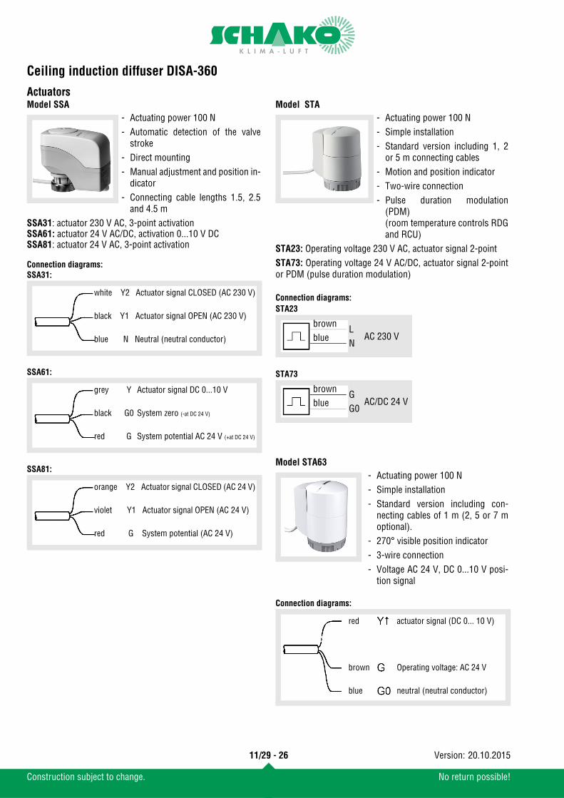
ActuatorsModel SSA
Connection diagrams:SSA31:
SSA61:
SSA81:
Model STA
Connection diagrams:STA23
STA73
Model STA63
Connection diagrams:
- Actuating power 100 N- Automatic detection of the valve
stroke- Direct mounting- Manual adjustment and position in-
dicator- Connecting cable lengths 1.5, 2.5
and 4.5 mSSA31: actuator 230 V AC, 3-point activationSSA61: actuator 24 V AC/DC, activation 0...10 V DCSSA81: actuator 24 V AC, 3-point activation
white Y2 Actuator signal CLOSED (AC 230 V)
black Y1 Actuator signal OPEN (AC 230 V)
blue N Neutral (neutral conductor)
grey Y Actuator signal DC 0...10 V
black G0 System zero (-at DC 24 V)
red G System potential AC 24 V (+at DC 24 V)
orange Y2 Actuator signal CLOSED (AC 24 V)
violet Y1 Actuator signal OPEN (AC 24 V)
red G System potential (AC 24 V)
- Actuating power 100 N- Simple installation- Standard version including 1, 2
or 5 m connecting cables- Motion and position indicator- Two-wire connection- Pulse duration modulation
(PDM)(room temperature controls RDGand RCU)
STA23: Operating voltage 230 V AC, actuator signal 2-pointSTA73: Operating voltage 24 V AC/DC, actuator signal 2-pointor PDM (pulse duration modulation)
- Actuating power 100 N- Simple installation- Standard version including con-
necting cables of 1 m (2, 5 or 7 moptional).
- 270° visible position indicator- 3-wire connection- Voltage AC 24 V, DC 0...10 V posi-
tion signal
brownblue
LN
AC 230 V
brownblue
GG0
AC/DC 24 V
red actuator signal (DC 0... 10 V)
brown Operating voltage: AC 24 V
blue neutral (neutral conductor)
11/29 - 26
Construction subject to change. No return possible!
20.10.2015Version:
Ceiling induction diffuser DISA-360
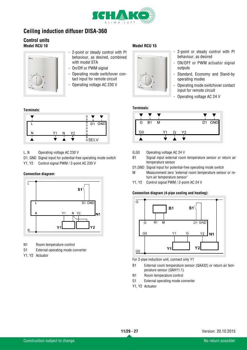
Control unitsModel RCU 10
Terminals:
Connection diagram:
Model RCU 15
Terminals:
Connection diagram (4-pipe cooling and heating):
For 2-pipe induction unit, connect only Y1
- 2-point or steady control with PIbehaviour, as desired, combinedwith model STA
- On/Off or PWM signal- Operating mode switchover con-
tact input for remote circuit- Operating voltage AC 230 V
L, N Operating voltage AC 230 VD1, GND Signal input for potential-free operating mode switchY1, Y2 Control signal PWM / 2-point AC 230 V
N1 Room temperature controlS1 External operating mode converterY1, Y2 Actuator
- 2-point or steady control with PIbehaviour, as desired
- ON/OFF or PWM actuator signaloutputs
- Standard, Economy and Stand-byoperating modes
- Operating mode switchover contactinput for remote circuit
- Operating voltage AC 24 V
G,G0 Operating voltage AC 24 VB1 Signal input external room temperature sensor or return air
temperature sensorD1,GND Signal input for potential-free operating mode switchM Measurement zero "external room temperature sensor or re-
turn air temperature sensor"Y1, Y2 Control signal PWM / 2-point AC 24 V
B1 External room temperature sensor (QAA32) or return air tem-perature sensor (QAH11.1)
N1 Room temperature controlS1 External operating mode converterY1, Y2 Actuator
11/29 - 27
Construction subject to change. No return possible!
20.10.2015Version:
Ceiling induction diffuser DISA-360
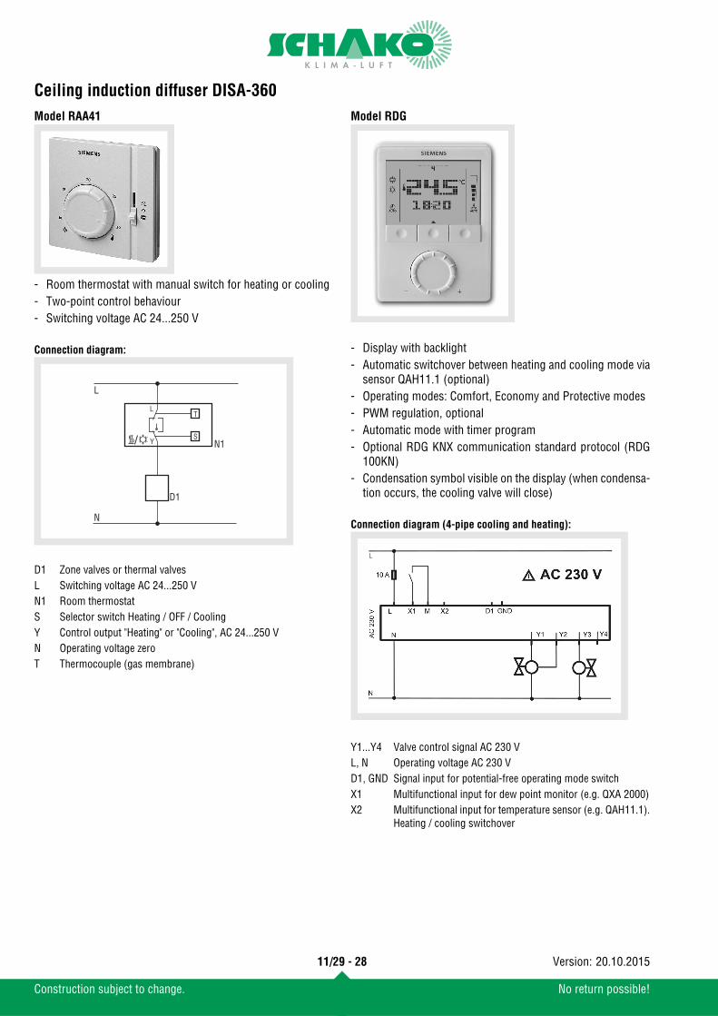
Model RAA41Connection diagram:
Model RDG
Connection diagram (4-pipe cooling and heating):
- Room thermostat with manual switch for heating or cooling- Two-point control behaviour- Switching voltage AC 24...250 V
D1 Zone valves or thermal valvesL Switching voltage AC 24...250 VN1 Room thermostatS Selector switch Heating / OFF / CoolingY Control output "Heating" or "Cooling", AC 24...250 VN Operating voltage zeroT Thermocouple (gas membrane)
L
L
Y
N
T
SN1
D1
- Display with backlight- Automatic switchover between heating and cooling mode via
sensor QAH11.1 (optional)- Operating modes: Comfort, Economy and Protective modes- PWM regulation, optional- Automatic mode with timer program- Optional RDG KNX communication standard protocol (RDG
100KN)- Condensation symbol visible on the display (when condensa-
tion occurs, the cooling valve will close)
Y1...Y4 Valve control signal AC 230 VL, N Operating voltage AC 230 VD1, GND Signal input for potential-free operating mode switchX1 Multifunctional input for dew point monitor (e.g. QXA 2000)X2 Multifunctional input for temperature sensor (e.g. QAH11.1).
Heating / cooling switchover
11/29 - 28
Construction subject to change. No return possible!
20.10.2015Version:
Ceiling induction diffuser DISA-360
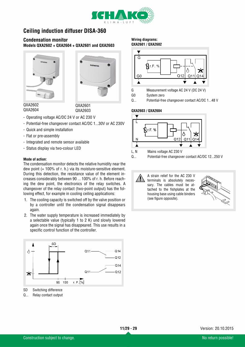
Condensation monitorModels QXA2602 + QXA2604 + QXA2601 and QXA2603
Mode of action:The condensation monitor detects the relative humidity near thedew point (= 100% of r. h.) via its moisture-sensitive element.During this detection, the resistance value of the element in-creases considerably between 90 ... 100% of r. h. Before reach-ing the dew point, the electronics of the relay switches. Achangeover of the relay contact (two-point output) has the fol-lowing effect, for example in cooling ceiling applications:
Wiring diagrams:QXA2601 / QXA2602
QXA2603 / QXA2604
QXA2602QXA2604
QXA2601QXA2603
- Operating voltage AC/DC 24 V or AC 230 V- Potential-free changeover contact AC/DC 1...30V or AC 230V- Quick and simple installation- Flat or pre-assembly- Integrated and remote sensor available- Status display via two-colour LED
1. The cooling capacity is switched off by the valve position orby a controller until the condensation signal disappearsagain.
2. The water supply temperature is increased immediately bya selectable value (typically 1 to 2 K) und slowly loweredagain once the signal has disappeared. This use results in aspecific control function of the controller.
SD Switching differenceQ... Relay contact output
G Measurement voltage AC 24 V (DC 24 V)G0 System zeroQ... Potential-free changeover contact AC/DC 1...48 V
L, N Mains voltage AC 230 VQ... Potential-free changeover contact AC/DC 12...250 V
A strain relief for the AC 230 Vterminals is absolutely neces-sary. The cables must be at-tached to the fishplates at thehousing base using cable binders(see figure opposite).
11/29 - 29
Construction subject to change. No return possible!
20.10.2015Version:
Ceiling induction diffuser DISA-360
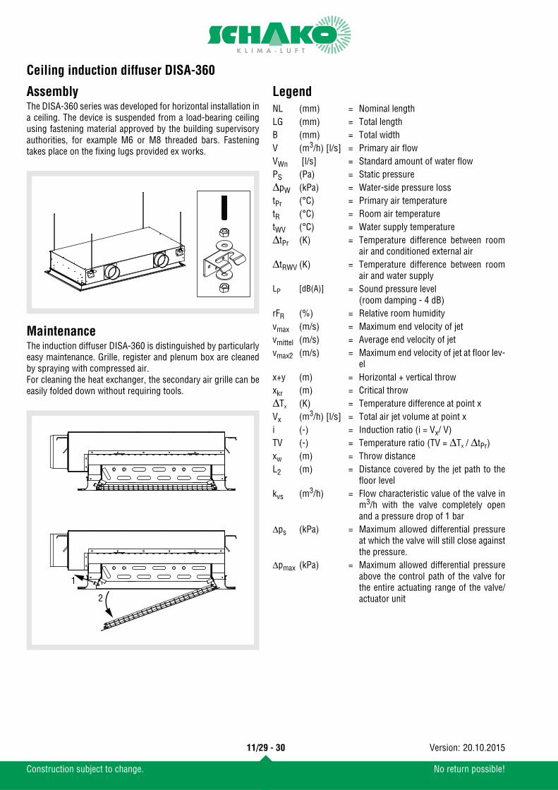
AssemblyThe DISA-360 series was developed for horizontal installation ina ceiling. The device is suspended from a load-bearing ceilingusing fastening material approved by the building supervisoryauthorities, for example M6 or M8 threaded bars. Fasteningtakes place on the fixing lugs provided ex works.
MaintenanceThe induction diffuser DISA-360 is distinguished by particularlyeasy maintenance. Grille, register and plenum box are cleanedby spraying with compressed air.For cleaning the heat exchanger, the secondary air grille can beeasily folded down without requiring tools.
Legend
1
2
NL (mm) = Nominal lengthLG (mm) = Total lengthB (mm) = Total width V (m3/h) [l/s] = Primary air flowVWn [l/s] = Standard amount of water flowPS (Pa) = Static pressureΔpW (kPa) = Water-side pressure losstPr (°C) = Primary air temperaturetR (°C) = Room air temperaturetWV (°C) = Water supply temperatureΔtPr (K) = Temperature difference between room
air and conditioned external airΔtRWV (K) = Temperature difference between room
air and water supplyLP [dB(A)] = Sound pressure level
(room damping - 4 dB)rFR (%) = Relative room humidityvmax (m/s) = Maximum end velocity of jetvmittel (m/s) = Average end velocity of jetvmax2 (m/s) = Maximum end velocity of jet at floor lev-
el x+y (m) = Horizontal + vertical throwxkr (m) = Critical throwΔTx (K) = Temperature difference at point xVx (m3/h) [l/s] = Total air jet volume at point xi (-) = Induction ratio (i = Vx/ V)TV (-) = Temperature ratio (TV = ΔTx / ΔtPr)xw (m) = Throw distanceL2 (m) = Distance covered by the jet path to the
floor levelkvs (m3/h) = Flow characteristic value of the valve in
m3/h with the valve completely openand a pressure drop of 1 bar
Δps (kPa) = Maximum allowed differential pressureat which the valve will still close againstthe pressure.
Δpmax (kPa) = Maximum allowed differential pressureabove the control path of the valve forthe entire actuating range of the valve/actuator unit
11/29 - 30
Construction subject to change. No return possible!
20.10.2015Version:
Ceiling induction diffuser DISA-360
Order details
Individually adjustable -LE
Connecting piece diameter
-98 -123
with louvre grid-PA
Horizontal connection -H
Water connection (not for -BO)
left -WS1
Nozzle configuration-B -C -D -E
with perforated sheet grille-SR -SQ -RE -OB
Total width -592 -597 -617 -622
with 1 connecting piece with 2 connecting pieces
-AS1 -AS2/AS3with 1 connecting piece with 2 connecting pieces
-AS4 -AS5/AS6
DISA-360
2-pipe system -H 4-pipe system -HT without register -BO
Total length
Unpainted register(-)
Painted register-R9005
-592 -1192Total length
-597 -1197Total length
-617 -1242Total length
-622 -1247
with air deflection blades without air deflection blades - OLBlockwise adjustable
-LB
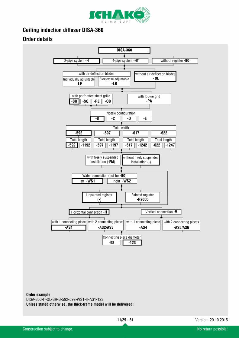
Order exampleDISA-360-H-OL-SR-B-592-592-WS1-H-AS1-123Unless stated otherwise, the thick-frame model will be delivered!
right -WS2
with freely suspendedinstallation (-FM)
without freely suspended installation (-)
Vertical connection -V
11/29 - 31
Construction subject to change. No return possible!
20.10.2015Version:
Ceiling induction diffuser DISA-360
Specification textCeiling induction diffuser DISA-360 for installation in false ceil-ings Housing made of galvanised sheet steel. With foldable lou-vre grid type SCHAKO-PA or perforated sheet made of sheetsteel painted to RAL 9010 (white, standard). Horizontal 2-pipe(standard) or 4-pipe register (optional) for cooling and heating,including galvanised sheet steel frame, copper pipes and alu-minium blades Four-way supply air throw and air deflectionblades (optional)Width: 592-622 mm, height: 220 mm, length: 592-1247 mm
Product: SCHAKO type DISA-360
- System- 2-pipe system (-H), standard- 4-pipe (-HT)- Without register (-BO)
- Air deflection blades- Individually adjustable (-LE)- Blockwise adjustable (-LB)- Without air deflection blades (-OL)
- Secondary air grille- Foldable perforated sheet, perforation Ø 6 mm (-SR, stand-
ard)- Foldable perforated sheet, perforation 8x8 mm (-SQ)- Foldable perforated sheet, perforation 12x5 (-RE)- Foldable perforated sheet, oval perforation 20x6 mm (-OB)
- Louvre grid (-PA)- Foldable louvre grid PA
- Nozzle configuration- B (standard)- C- D- E
- Total width - 592- 597- 617- 622
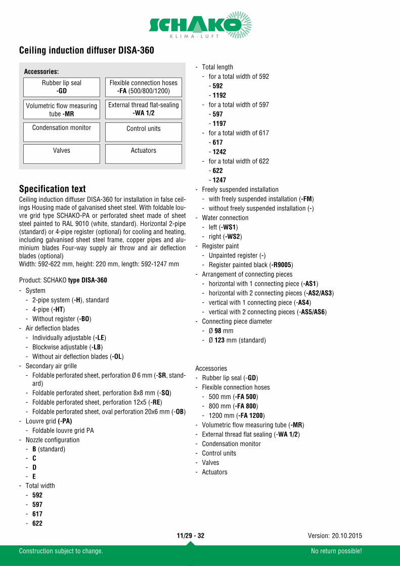
Accessories:
Condensation monitor
Valves Actuators
Control units
Volumetric flow measuring tube -MR
Rubber lip seal-GD
External thread flat-sealing-WA 1/2
Flexible connection hoses-FA (500/800/1200)
- Total length- for a total width of 592
- 592- 1192
- for a total width of 597 - 597- 1197
- for a total width of 617 - 617- 1242
- for a total width of 622 - 622- 1247
- Freely suspended installation- with freely suspended installation (-FM)- without freely suspended installation (-)
- Water connection- left (-WS1)- right (-WS2)
- Register paint- Unpainted register (-)- Register painted black (-R9005)
- Arrangement of connecting pieces- horizontal with 1 connecting piece (-AS1)- horizontal with 2 connecting pieces (-AS2/AS3)- vertical with 1 connecting piece (-AS4)- vertical with 2 connecting pieces (-AS5/AS6)
- Connecting piece diameter- Ø 98 mm- Ø 123 mm (standard)
Accessories- Rubber lip seal (-GD)- Flexible connection hoses
- 500 mm (-FA 500)- 800 mm (-FA 800)- 1200 mm (-FA 1200)
- Volumetric flow measuring tube (-MR)- External thread flat sealing (-WA 1/2)- Condensation monitor- Control units- Valves- Actuators
11/29 - 32
Construction subject to change. No return possible!
20.10.2015Version:


