Septermber, 2000 Oil Free Repair Manual 12 TAB: Disassembly and Repair T ools needed: Tools Needed: Phillips Screwdriver ● Needle Nose Pliers ● 5/16” Nut Driver ● Adjustable Crescent Wrench ● 7/16” Crescent Wrench ● 3/8” Nut Driver and Socket Wrench ● T20-Torx Wrench ● Flat-head Screwdriver ● Large Screw Driver, ● Rubber Mallet ● Air Impact Wrench, with a Bar Extension and 7/8” Socket WARNING! Before making any repairs, be sure the unit is unplugged and tank has no air. SINGLE CYLINDER OIL-FREE PORTABLE 1. To remove the line and load cords from the pressure switch, the pressure switch cover will need to be removed. a. Use your Phillips head screwdriver to loosen the screw located either on the top or on the side of the cover. b. Unhook all of the black and white wires from the pressure switch using the needle nose pliers. DISASSEMBLY & REPAIR PROCEDURES
Transcript
Septermber, 2000Oil Free Repair Manual 12 TAB: Disassembly and Repair
Tools needed: Tools Needed: Phillips Screwdriver � Needle Nose Pliers � 5/16” Nut Driver� Adjustable Crescent Wrench � 7/16” Crescent Wrench � 3/8” Nut Driverand Socket Wrench � T20-Torx Wrench � Flat-head Screwdriver � LargeScrew Driver, � Rubber Mallet � Air Impact Wrench, with a Bar Extensionand 7/8” Socket
WARNING! Before making any repairs,be sure the unit is unplugged and tankhas no air.
SINGLE CYLINDER OIL-FREE PORTABLE
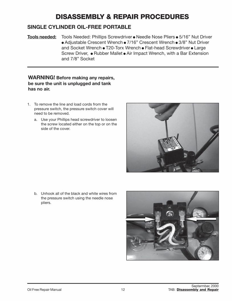
1. To remove the line and load cords from thepressure switch, the pressure switch cover willneed to be removed.
a. Use your Phillips head screwdriver to loosenthe screw located either on the top or on theside of the cover.
b. Unhook all of the black and white wires fromthe pressure switch using the needle nosepliers.
DISASSEMBLY & REPAIR PROCEDURES
Septermber, 2000Oil Free Repair Manual 13 TAB: Disassembly and Repair
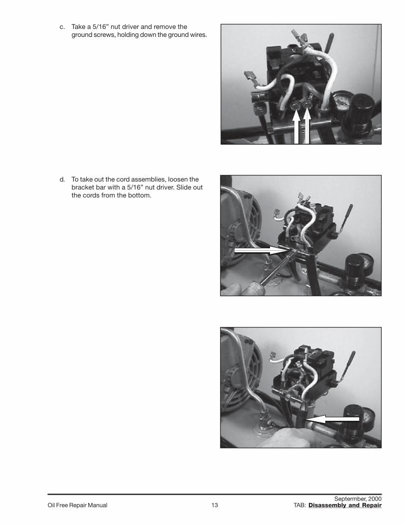
c. Take a 5/16” nut driver and remove theground screws, holding down the ground wires.
d. To take out the cord assemblies, loosen thebracket bar with a 5/16” nut driver. Slide outthe cords from the bottom.
Septermber, 2000Oil Free Repair Manual 14 TAB: Disassembly and Repair
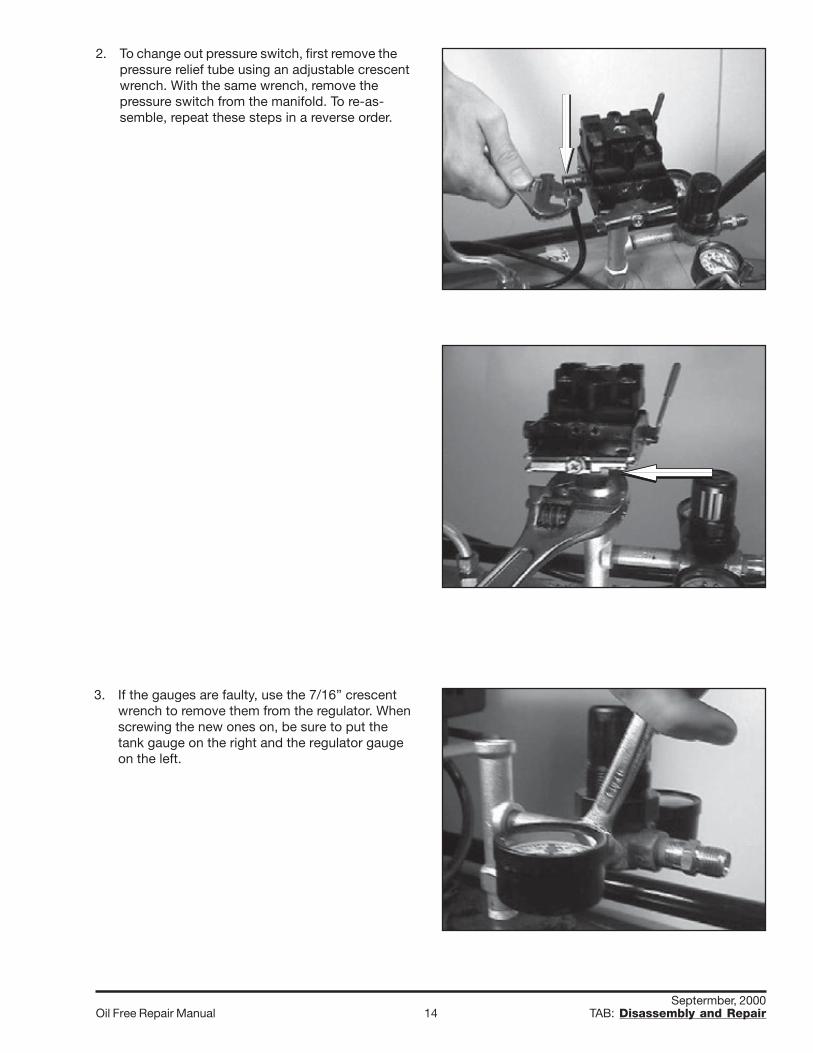
2. To change out pressure switch, first remove thepressure relief tube using an adjustable crescentwrench. With the same wrench, remove thepressure switch from the manifold. To re-as-semble, repeat these steps in a reverse order.
3. If the gauges are faulty, use the 7/16” crescentwrench to remove them from the regulator. Whenscrewing the new ones on, be sure to put thetank gauge on the right and the regulator gaugeon the left.
Septermber, 2000Oil Free Repair Manual 15 TAB: Disassembly and Repair
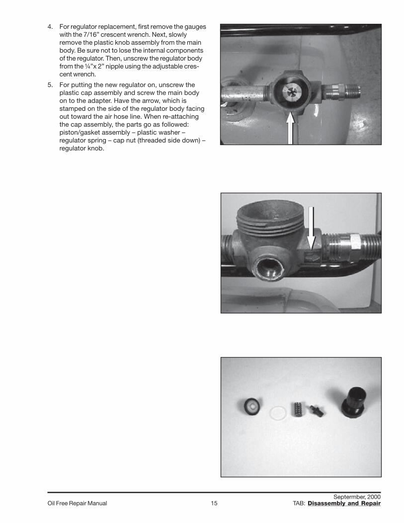
4. For regulator replacement, first remove the gaugeswith the 7/16” crescent wrench. Next, slowlyremove the plastic knob assembly from the mainbody. Be sure not to lose the internal componentsof the regulator. Then, unscrew the regulator bodyfrom the ¼”x 2” nipple using the adjustable cres-cent wrench.
5. For putting the new regulator on, unscrew theplastic cap assembly and screw the main bodyon to the adapter. Have the arrow, which isstamped on the side of the regulator body facingout toward the air hose line. When re-attachingthe cap assembly, the parts go as followed:piston/gasket assembly – plastic washer –regulator spring – cap nut (threaded side down) –regulator knob.
Septermber, 2000Oil Free Repair Manual 16 TAB: Disassembly and Repair
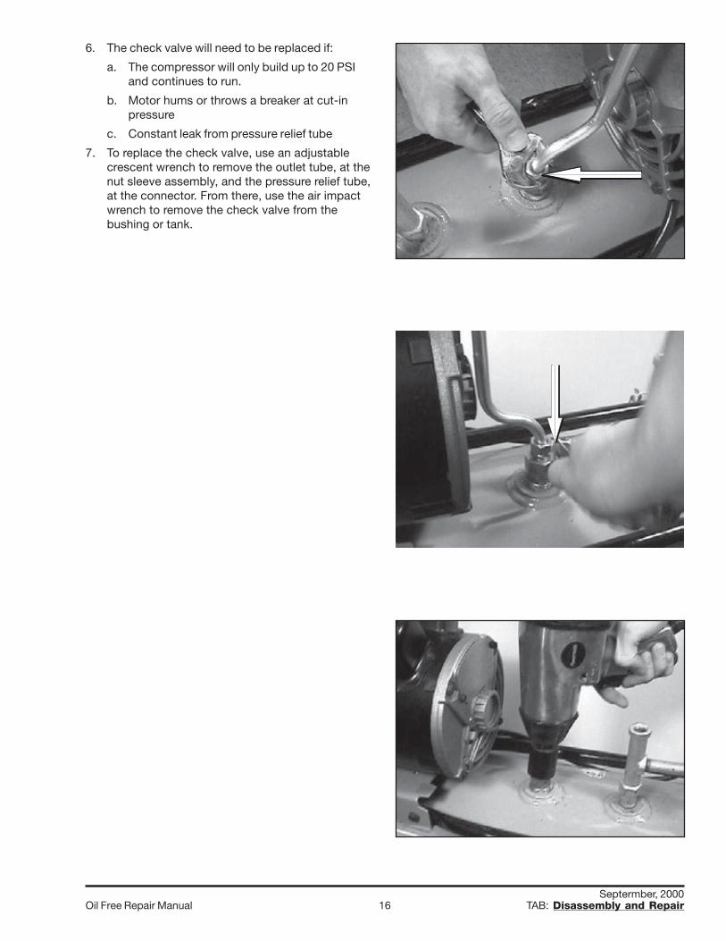
6. The check valve will need to be replaced if:
a. The compressor will only build up to 20 PSIand continues to run.
b. Motor hums or throws a breaker at cut-inpressure
c. Constant leak from pressure relief tube
7. To replace the check valve, use an adjustablecrescent wrench to remove the outlet tube, at thenut sleeve assembly, and the pressure relief tube,at the connector. From there, use the air impactwrench to remove the check valve from thebushing or tank.
Septermber, 2000Oil Free Repair Manual 17 TAB: Disassembly and Repair
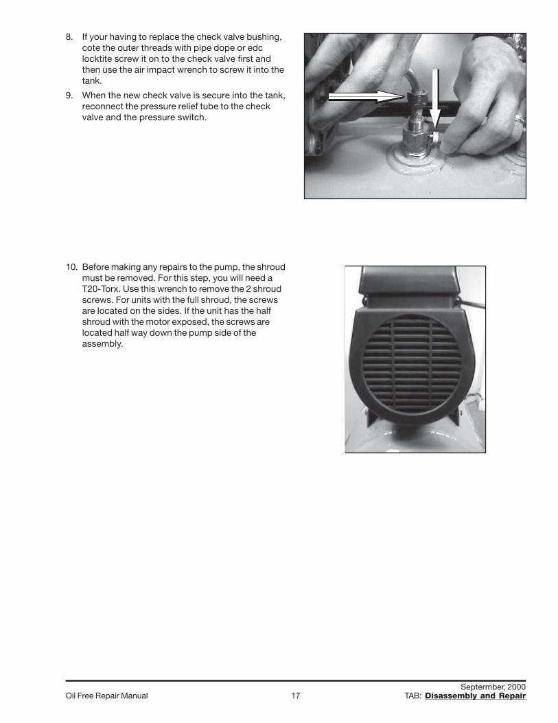
8. If your having to replace the check valve bushing,cote the outer threads with pipe dope or edclocktite screw it on to the check valve first andthen use the air impact wrench to screw it into thetank.
9. When the new check valve is secure into the tank,reconnect the pressure relief tube to the checkvalve and the pressure switch.
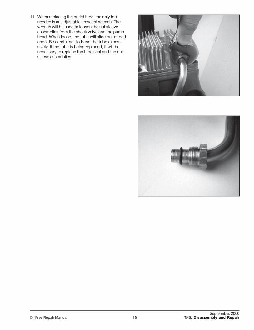
10. Before making any repairs to the pump, the shroudmust be removed. For this step, you will need aT20-Torx. Use this wrench to remove the 2 shroudscrews. For units with the full shroud, the screwsare located on the sides. If the unit has the halfshroud with the motor exposed, the screws arelocated half way down the pump side of theassembly.
Septermber, 2000Oil Free Repair Manual 18 TAB: Disassembly and Repair
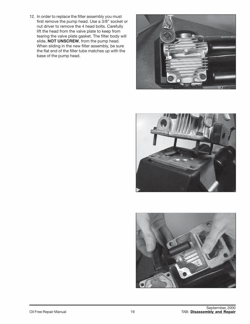
11. When replacing the outlet tube, the only toolneeded is an adjustable crescent wrench. Thewrench will be used to loosen the nut sleeveassemblies from the check valve and the pumphead. When loose, the tube will slide out at bothends. Be careful not to bend the tube exces-sively. If the tube is being replaced, it will benecessary to replace the tube seal and the nutsleeve assemblies.
Septermber, 2000Oil Free Repair Manual 19 TAB: Disassembly and Repair
12. In order to replace the filter assembly you mustfirst remove the pump head. Use a 3/8” socket ornut driver to remove the 4 head bolts. Carefullylift the head from the valve plate to keep fromtearing the valve plate gasket. The filter body willslide, NOT UNSCREW, from the pump head.When sliding in the new filter assembly, be surethe flat end of the filter tube matches up with thebase of the pump head.
Septermber, 2000Oil Free Repair Manual 20 TAB: Disassembly and Repair
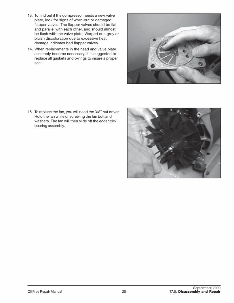
13. To find out if the compressor needs a new valveplate, look for signs of worn-out or damagedflapper valves. The flapper valves should be flatand parallel with each other, and should almostbe flush with the valve plate. Warped or a gray orbluish discoloration due to excessive heatdamage indicates bad flapper valves.
14. When replacements in the head and valve plateassembly become necessary, it is suggested toreplace all gaskets and o-rings to insure a properseal.
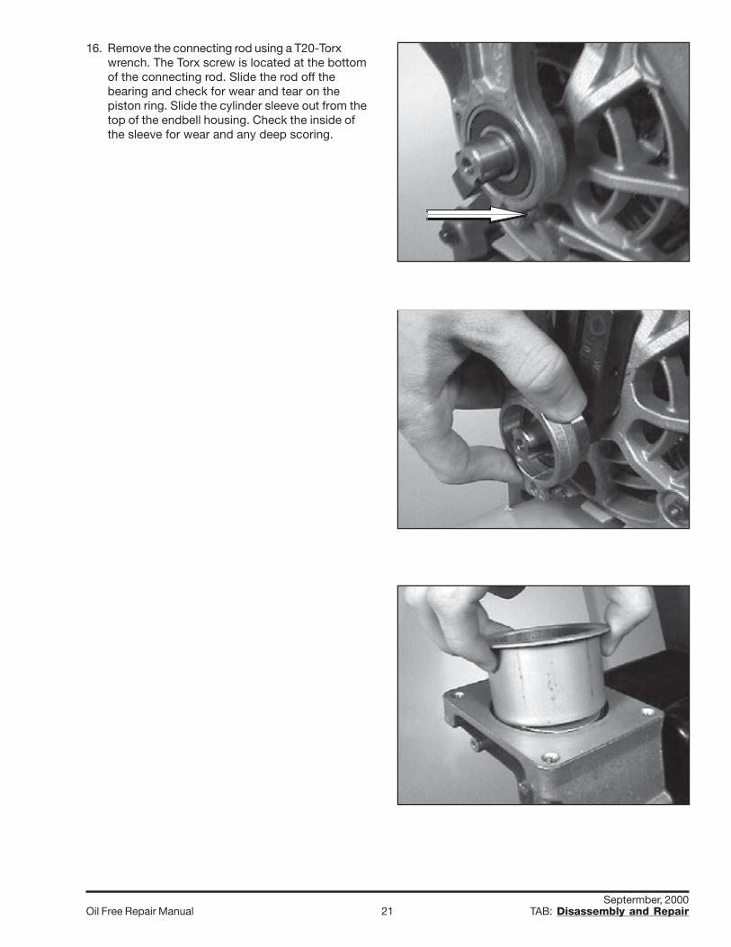
15. To replace the fan, you will need the 3/8” nut driver.Hold the fan while unscrewing the fan bolt andwashers. The fan will then slide off the eccentric/bearing assembly.
Septermber, 2000Oil Free Repair Manual 21 TAB: Disassembly and Repair
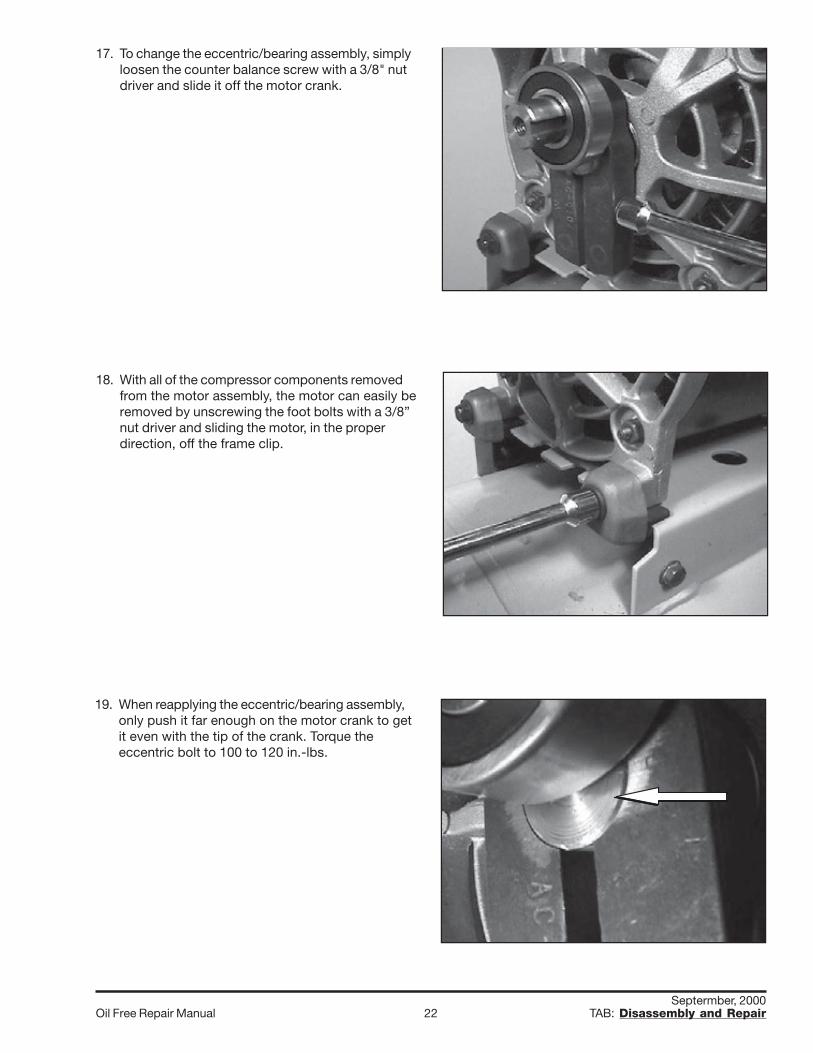
16. Remove the connecting rod using a T20-Torxwrench. The Torx screw is located at the bottomof the connecting rod. Slide the rod off thebearing and check for wear and tear on thepiston ring. Slide the cylinder sleeve out from thetop of the endbell housing. Check the inside ofthe sleeve for wear and any deep scoring.
Septermber, 2000Oil Free Repair Manual 22 TAB: Disassembly and Repair
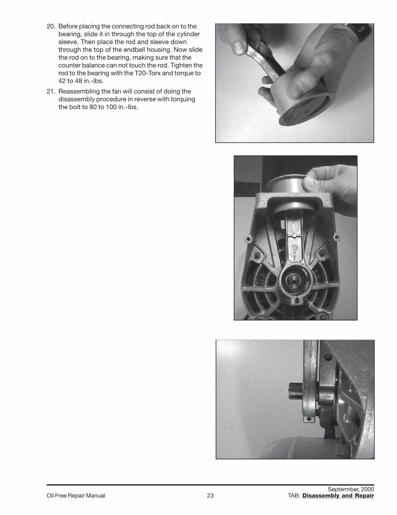
17. To change the eccentric/bearing assembly, simplyloosen the counter balance screw with a 3/8" nutdriver and slide it off the motor crank.
18. With all of the compressor components removedfrom the motor assembly, the motor can easily beremoved by unscrewing the foot bolts with a 3/8”nut driver and sliding the motor, in the properdirection, off the frame clip.
19. When reapplying the eccentric/bearing assembly,only push it far enough on the motor crank to getit even with the tip of the crank. Torque theeccentric bolt to 100 to 120 in.-lbs.
Septermber, 2000Oil Free Repair Manual 23 TAB: Disassembly and Repair
20. Before placing the connecting rod back on to thebearing, slide it in through the top of the cylindersleeve. Then place the rod and sleeve downthrough the top of the endbell housing. Now slidethe rod on to the bearing, making sure that thecounter balance can not touch the rod. Tighten therod to the bearing with the T20-Torx and torque to42 to 48 in.-lbs.
21. Reassembling the fan will consist of doing thedisassembly procedure in reverse with torquingthe bolt to 80 to 100 in.-lbs.
Septermber, 2000Oil Free Repair Manual 24 TAB: Disassembly and Repair
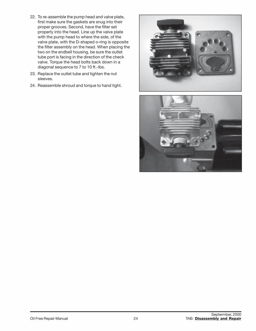
22. To re-assemble the pump head and valve plate,first make sure the gaskets are snug into theirproper grooves. Second, have the filter setproperly into the head. Line up the valve platewith the pump head to where the side, of thevalve plate, with the D-shaped o-ring is oppositethe filter assembly on the head. When placing thetwo on the endbell housing, be sure the outlettube port is facing in the direction of the checkvalve. Torque the head bolts back down in adiagonal sequence to 7 to 10 ft.-lbs.
23. Replace the outlet tube and tighten the nutsleeves.