DISASSEMBLY PROCEDURE 2 - 1 Chapter 2 Disassembly Procedure Please follow the information provided in this section to perform the complete disassembly procedure of the notebook. Be sure to use proper tools described before. SUS M2400Ne (ID1) Series Notebook consists of various modules. This chapter describes the procedures for the complete notebook disassembly. In addition, in between procedures, the detailed disassembly procedure of individual modules will be provided for your service needs. The disassembly procedure consists of the following steps: • Battery module • Optical drive Module • HDD Module • Memory Module • CPU Module • Keyboard Module • Mini-PCI Module • LCD Module • Top Case Module • Motherboard Module • Modem Module • Bottom Case Module A
Transcript
D I S A S S E M B L Y P R O C E D U R E
2 - 1
Chapter
2 Disassembly Procedure Please follow the information provided in this section to perform the complete disassembly procedure of the notebook. Be sure to use proper tools described before.
SUS M2400Ne (ID1) Series Notebook consists of various modules. This chapter describes the procedures for the complete notebook disassembly. In addition, in between procedures, the detailed disassembly procedure of individual modules will be provided for your service needs.
The disassembly procedure consists of the following steps: • Battery module • Optical drive Module • HDD Module • Memory Module • CPU Module • Keyboard Module • Mini-PCI Module • LCD Module • Top Case Module • Motherboard Module • Modem Module • Bottom Case Module
A
D I S A S S E M B L Y P R O C E D U R E
2 - 2
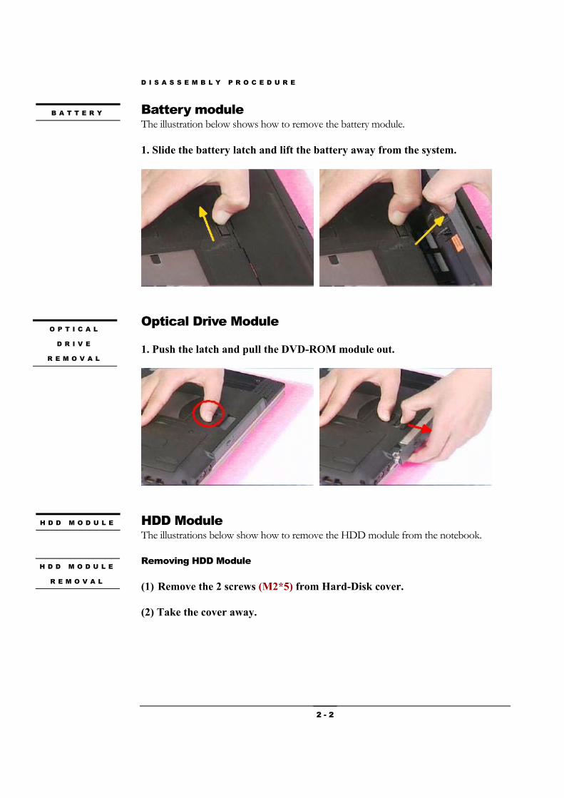
Battery module The illustration below shows how to remove the battery module.
1. Slide the battery latch and lift the battery away from the system.
Optical Drive Module
1. Push the latch and pull the DVD-ROM module out.
HDD Module The illustrations below show how to remove the HDD module from the notebook. Removing HDD Module
(1) Remove the 2 screws (M2*5) from Hard-Disk cover.
(2) Take the cover away.
B A T T E R Y
H D D M O D U L E
R E M O V A L
H D D M O D U L E
O P T I C A L
D R I V E
R E M O V A L
D I S A S S E M B L Y P R O C E D U R E
2 - 3
(3) Remove the 2 screws (M2*5).
(4) Pull the Hard Disk out of the system.
Please do not touch inside of the HDD module. Memory Module The illustrations below show how to remove the Memory module from the notebook. The M2400 NE (ID1) Series Notebook comes standard with 256MB of RAM onboard. There is one expansion SODIMM socket for you to upgrade the total memory up to 768MB with a 512 MB module Removing Memory module
(1) Remove the 3 screws (M2*5) from DIMM cover.
(2) Take the cover away.
(3) Remove SO-DIMM by opening the two latches to pop up it.
(4) Pull the SO-DIMM out.
M E M O R Y
R E M O V A L
M E M O R Y
M O D U L E
D I S A S S E M B L Y P R O C E D U R E
2 - 4
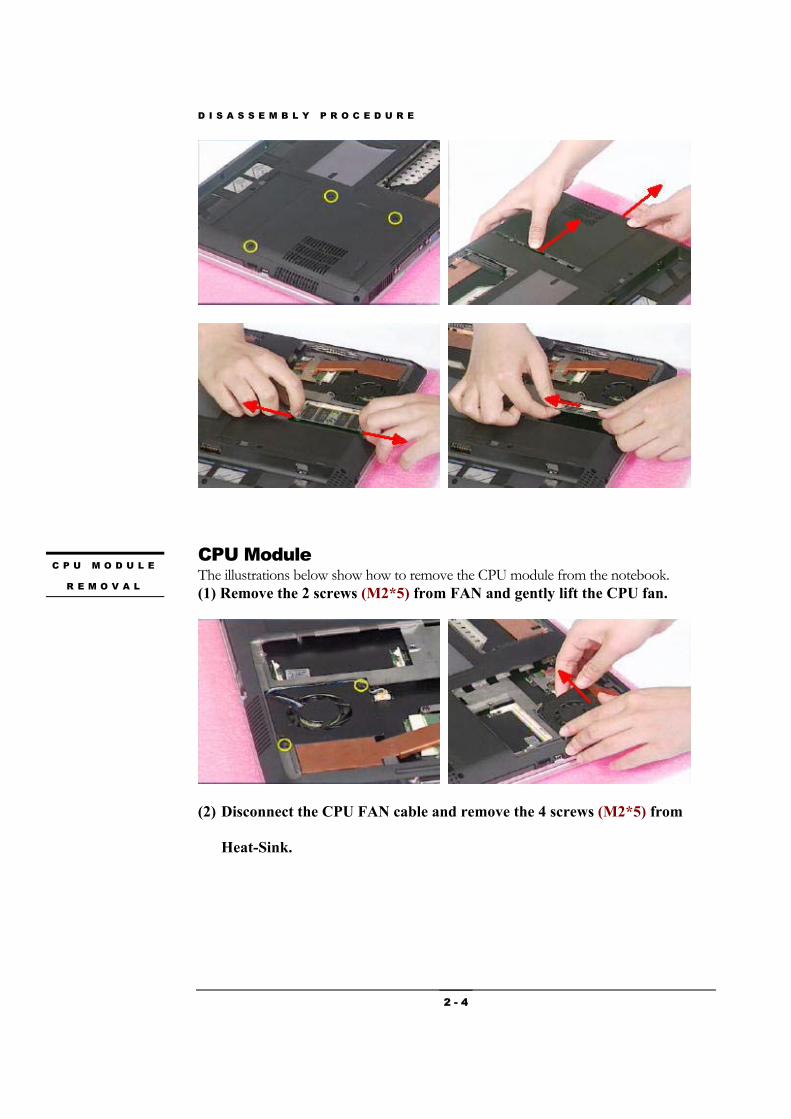
CPU Module The illustrations below show how to remove the CPU module from the notebook. (1) Remove the 2 screws (M2*5) from FAN and gently lift the CPU fan.
(2) Disconnect the CPU FAN cable and remove the 4 screws (M2*5) from
Heat-Sink.
C P U M O D U L E
R E M O V A L
D I S A S S E M B L Y P R O C E D U R E
2 - 5
(3) Then lift the CPU heat-sink module and carefully remove the CPU
thermal pad.
(3) Turn the non-removable screw here 180 degrees counter-clockwise to
loose the CPU and squeeze the vacuum handling pump and use it to lift
the CPU away.
Keyboard Module The illustration below shows how to remove the K/B plate.
K / B M O D U L E
D I S A S S E M B L Y P R O C E D U R E
2 - 6
Removing K/B (1) Press the delete key and lift the right side of keyboard cover.
(2) Slide the cover along right side.
(3) Disconnect the cable, and take the keyboard cover away.
(4) Disconnect the cable from keyboard cover.
(5) Remove 2 screws (M2*5).
(6) Slide forward the keyboard and pull the keyboard up.
K / B
R E M O V A L
D I S A S S E M B L Y P R O C E D U R E
2 - 7
Removing Keyboard Cable 1. Use a flexible connector tool to unlock the cable connector on both ends (no. 1). 2. Carefully pull out the keyboard cable (no. 2) with a pair or tweezers. 3. Lock the connector (no. 3) again to avoid possible breakage. 4. Finally the keyboard plate can be removed from the notebook. Mini - PCI Module The illustrations below show how to remove and disassemble the Mini-PCI module. Removing Mini - PCI Module (1) Remove it by opening the latches, which will pop the module up to a 45°
angles, and then pulling out the module in that angle (2) Remove the Antenna cable from Mini-PCI module.
C A B L E
R E M O V A L
1. Unlock
2. Cable out
3.
1. Unlock
3.
M I N I - P C I
M I N I - P C I
R E M O V A L
D I S A S S E M B L Y P R O C E D U R E
2 - 8
LCD Module The illustrations below show how to remove and disassemble the LCD module. The module contains LCD panel, inverter board, LCD hinge bracket, hinge cover, antenna, LCD front cover and LCD bottom case. Disassembling LCD Module (1) Remove the 2 screws (M2.5*6) of hinge from the bottom side.
(2) Remove the LCD hinge covers.
(3) Remove the LCD harness cover, be careful the Antenna.
(4) Remove the 2 screws (M2.5*6) from the hinge feet on both sides.
L C D
L C D
D I S A S S E M B L Y
D I S A S S E M B L Y P R O C E D U R E
2 - 9
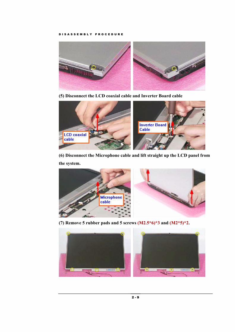
(5) Disconnect the LCD coaxial cable and Inverter Board cable
(6) Disconnect the Microphone cable and lift straight up the LCD panel from
the system.
(7) Remove 5 rubber pads and 5 screws (M2.5*6)*3 and (M2*5)*2.
D I S A S S E M B L Y P R O C E D U R E
2 - 10
(8) Carefully pry the inside edges of LCD front cover and take it away.
(9) Remove LCD cable from inverter board.
(10) Remove 2 screws (M2*3) from both sides.
(11) Take the LCD panel away.
(12) Disconnect the LCD coaxial cable.
(13) Remove the microphone line.
(14) take the inverter board module away.
D I S A S S E M B L Y P R O C E D U R E
2 - 11
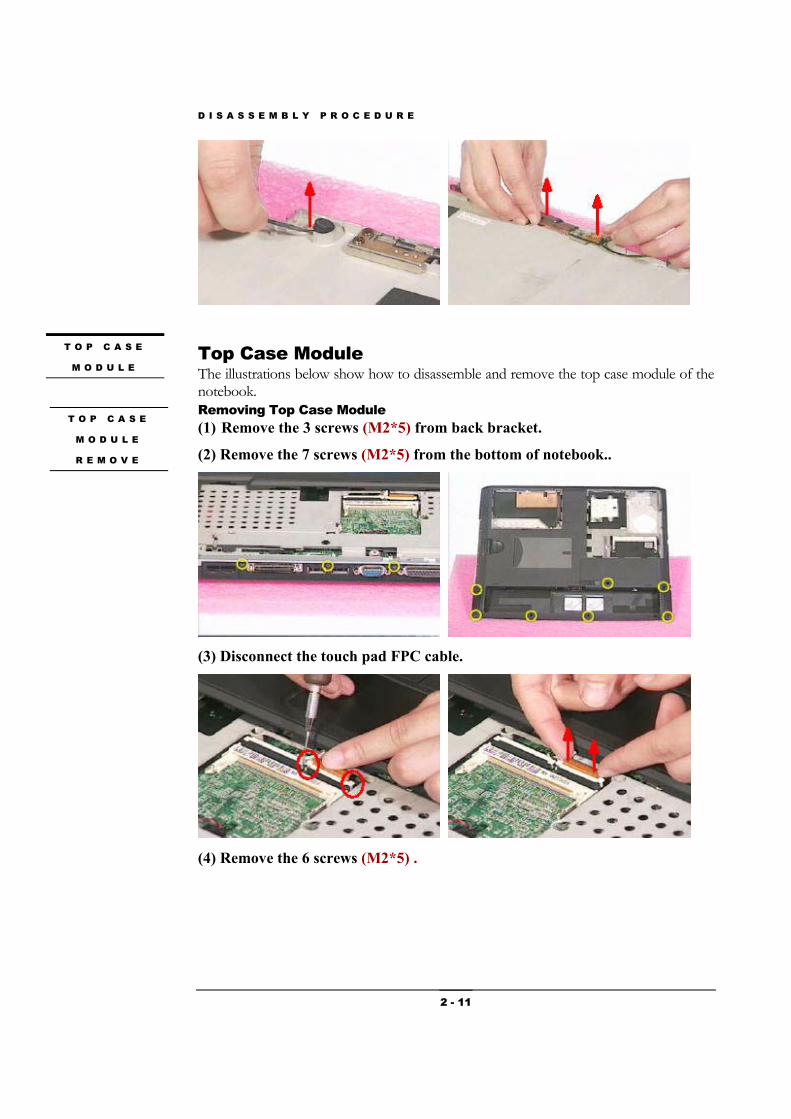
Top Case Module The illustrations below show how to disassemble and remove the top case module of the notebook. Removing Top Case Module (1) Remove the 3 screws (M2*5) from back bracket.
(2) Remove the 7 screws (M2*5) from the bottom of notebook..
(3) Disconnect the touch pad FPC cable.
(4) Remove the 6 screws (M2*5) .
T O P C A S E
M O D U L E
T O P C A S E
M O D U L E
R E M O V E
D I S A S S E M B L Y P R O C E D U R E
2 - 12
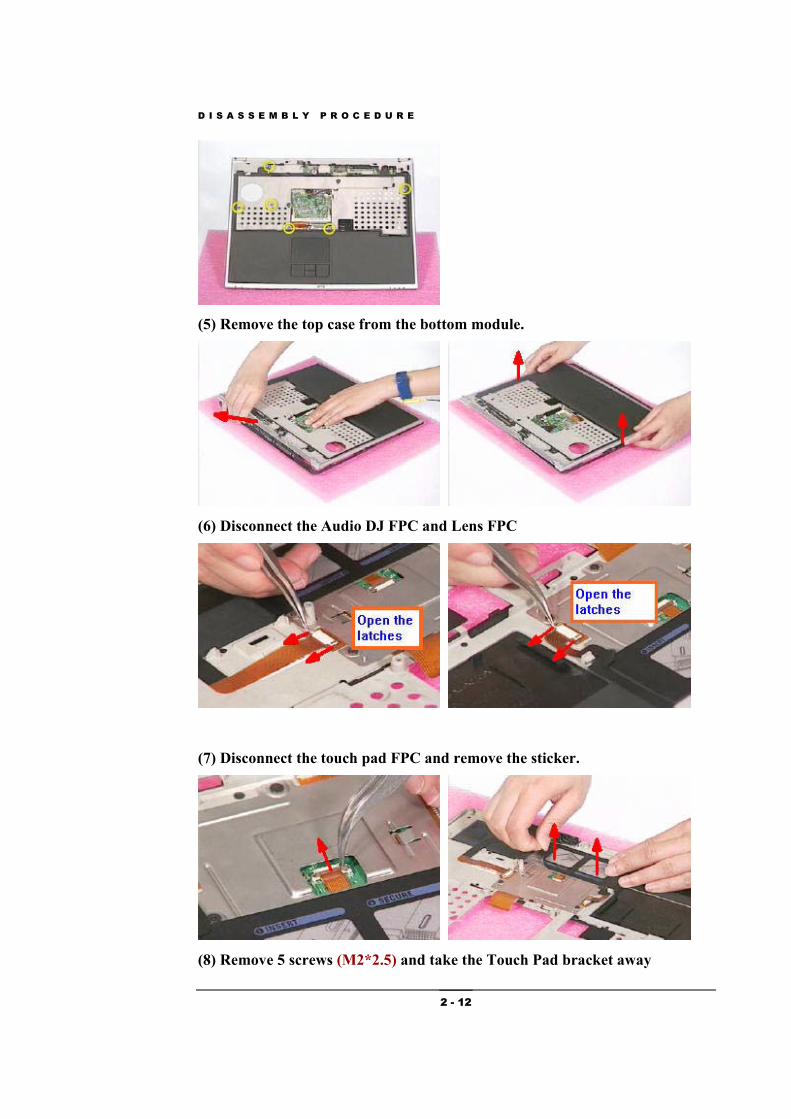
(5) Remove the top case from the bottom module.
(6) Disconnect the Audio DJ FPC and Lens FPC
(7) Disconnect the touch pad FPC and remove the sticker.
(8) Remove 5 screws (M2*2.5) and take the Touch Pad bracket away
D I S A S S E M B L Y P R O C E D U R E
2 - 13
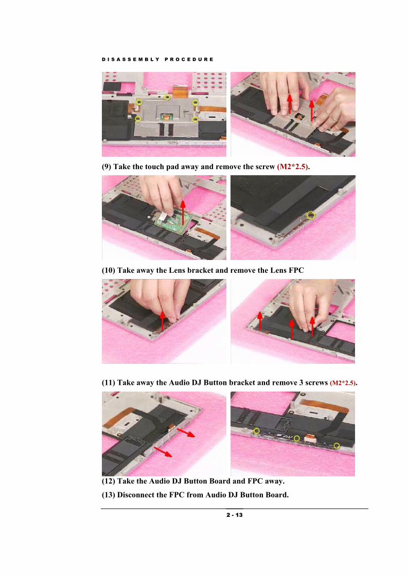
(9) Take the touch pad away and remove the screw (M2*2.5).
(10) Take away the Lens bracket and remove the Lens FPC
(11) Take away the Audio DJ Button bracket and remove 3 screws (M2*2.5).
(12) Take the Audio DJ Button Board and FPC away.
(13) Disconnect the FPC from Audio DJ Button Board.
D I S A S S E M B L Y P R O C E D U R E
2 - 14
M/B Module The illustrations below show how to disassemble and remove the motherboard module of the notebook. (1) Disconnect the speaker cable and disconnect the Audio DJ Power cable.
(2) Remove this screw (M2*5) and remove the DVD-ROM FPC connector.
(3) Remove the 2 screws (M2*5) .
M / B M O D U L E
M / B M O D U L E
R E M O V A L
D I S A S S E M B L Y P R O C E D U R E
2 - 15
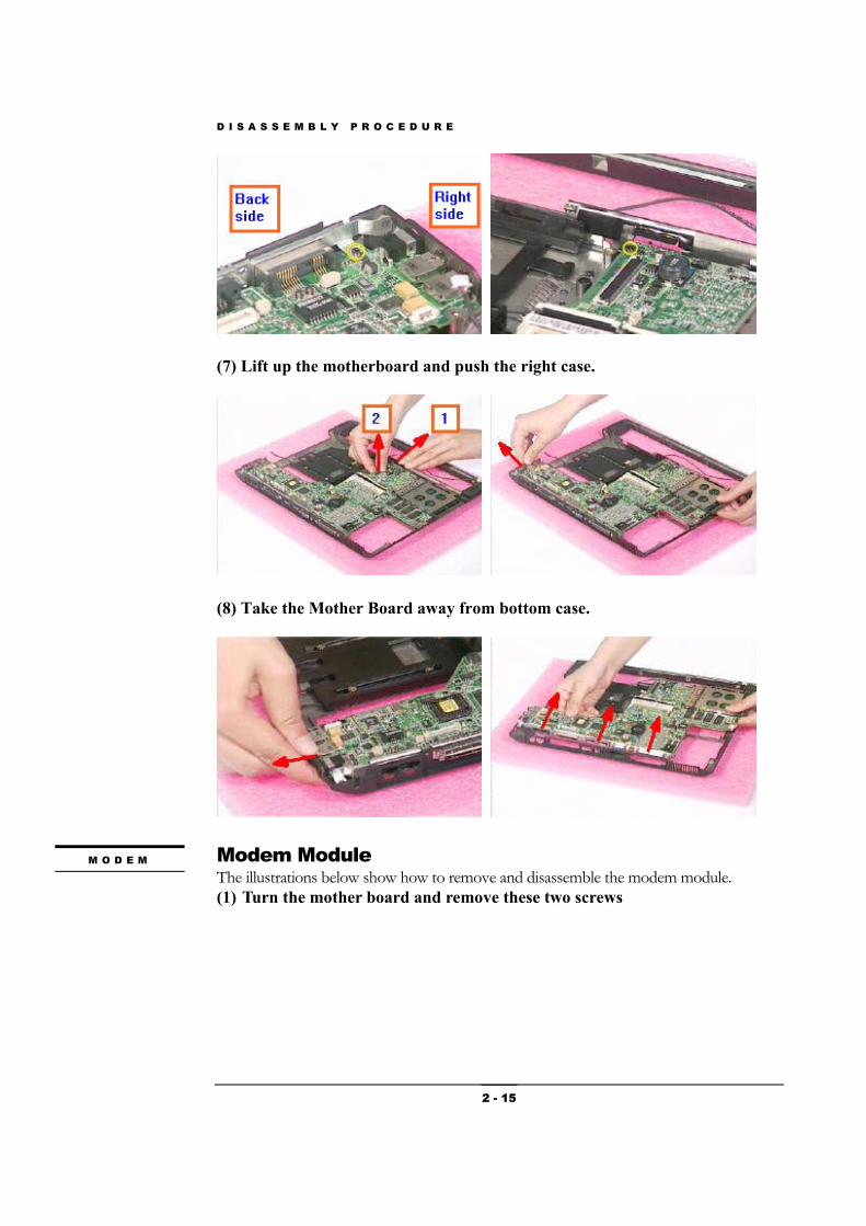
(7) Lift up the motherboard and push the right case.
(8) Take the Mother Board away from bottom case.
Modem Module The illustrations below show how to remove and disassemble the modem module. (1) Turn the mother board and remove these two screws
M O D E M
D I S A S S E M B L Y P R O C E D U R E
2 - 16
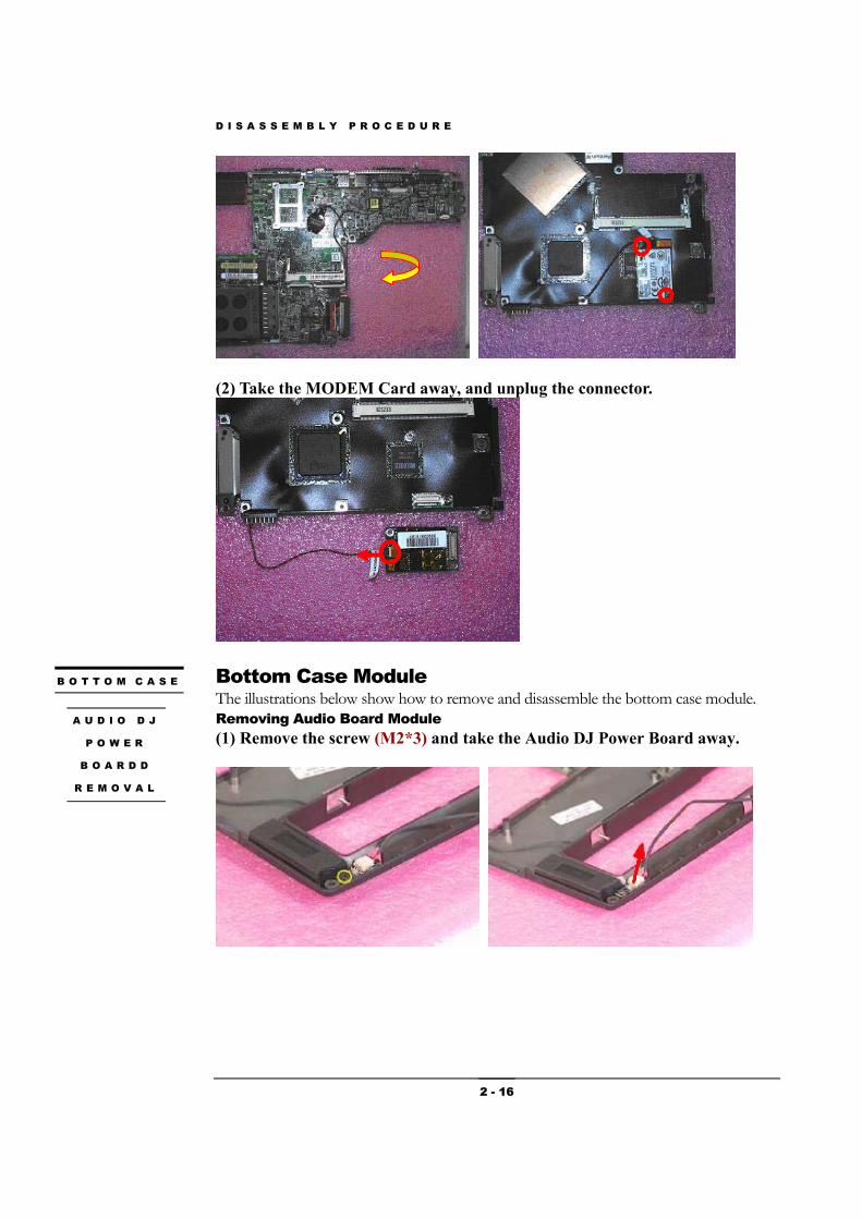
(2) Take the MODEM Card away, and unplug the connector.
Bottom Case Module The illustrations below show how to remove and disassemble the bottom case module. Removing Audio Board Module (1) Remove the screw (M2*3) and take the Audio DJ Power Board away.