CD-ROM DISCLAIMER - 1 Revision 1 December 1996 DISCLAIMER The U.S. Environmental Protection Agency's Office of Solid Waste (EPA or the Agency) has compiled this methods manual in order to provide comprehensive guidance to analysts, data users, and other interested parties regarding test methods that may be employed for the evaluation of solid waste and other testing specified in regulations issued under the Resource Conservation and Recovery Act (RCRA). Except where explicitly specified in a regulation, the use of SW-846 methods is not mandatory in response to Federal testing requirements. The Agency does not intend to restrict the use of new analytical techniques. Advances in technologies applicable to the sampling and analysis of environmental media and hazardous wastes outpace the ability of the Agency to promulgate revisions to this manual. In addition, given the large number of manufacturers and vendors of scientific equipment, glassware, reagents, and supplies, it is not feasible to cite all possible sources for these materials. Thus, the mention of trade names or commercial products in this manual is for illustrative purposes only, and does not constitute an endorsement or exclusive recommendation for use by EPA. The products and instrument settings cited in SW-846 methods represent those products and settings used during method development or subsequently evaluated by the Agency. Glassware, reagents, supplies, equipment, and settings other than those listed in this manual may be employed provided that method performance appropriate for the intended RCRA application has been documented as described in Chapter Two (see Sec. 2.1). EPA generally does not intend these methods to be overly prescriptive. The words "shall," "must," or "require" are used to indicate aspects of the method that are considered essential to its performance, based on sound analytical practices (e.g., an instrument must be calibrated before use). In contrast, the words "should," "may," or "recommend" are used to provide guidance on aspects of the method that are useful but not essential. This flexibility does not apply to those method-defined parameters where the analytical result is wholly dependant on the process used to make the measurement. EPA emphasizes that the ultimate responsibility for producing reliable analytical results lies with the entity subject to the Federal, State, or local regulation. Thus, members of the regulated community are advised to refer to the information in Chapter Two and to consult with knowledgeable laboratory personnel when choosing the most appropriate suite of analytical methods. The regulated community is further advised that the methods here or from other sources need only be used for those specific analytes of concern that are subject to regulation or other monitoring requirements. Many of the methods include performance data that are intended as guidance on the performance that may be achieved in typical matrices and may be used by the analyst to select the appropriate method for the intended application. These performance data are not intended to be used as absolute QC acceptance criteria. Rather, each laboratory should develop performance criteria as described in Chapter Two and elsewhere in the manual. In summary, the methods included here provide guidance to the analyst and the regulated community in making judgements necessary to generate data that meet the data quality objectives for the intended use of the results.
Transcript
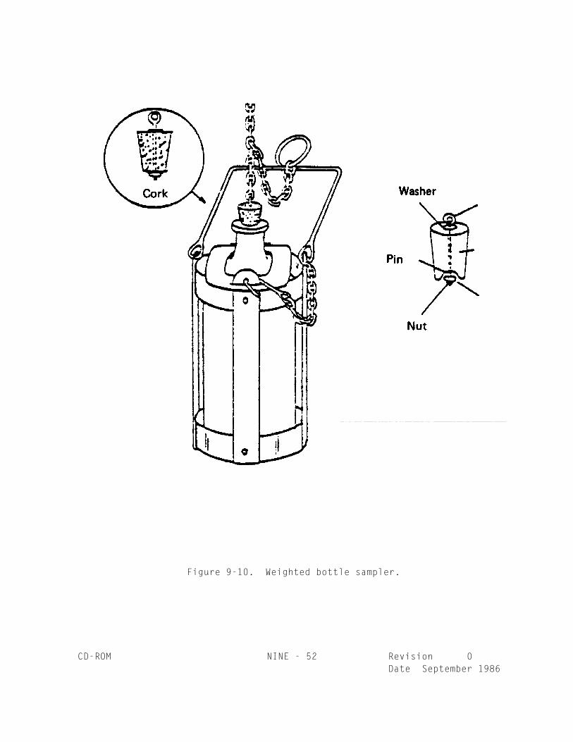
CD-ROM DISCLAIMER - 1 Revision 1December 1996
DISCLAIMER
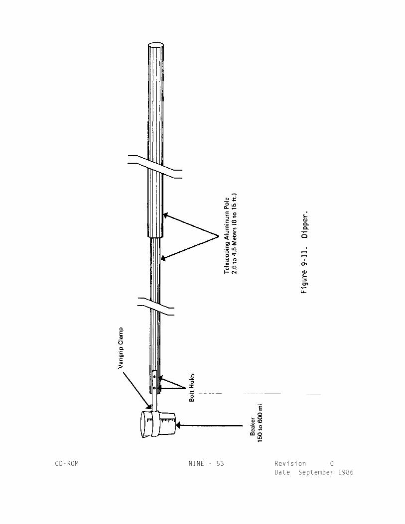
The U.S. Environmental Protection Agency's Office of Solid Waste (EPA or the Agency) hascompiled this methods manual in order to provide comprehensive guidance to analysts, data users,and other interested parties regarding test methods that may be employed for the evaluation of solidwaste and other testing specified in regulations issued under the Resource Conservation andRecovery Act (RCRA). Except where explicitly specified in a regulation, the use of SW-846 methodsis not mandatory in response to Federal testing requirements.
The Agency does not intend to restrict the use of new analytical techniques. Advances intechnologies applicable to the sampling and analysis of environmental media and hazardous wastesoutpace the ability of the Agency to promulgate revisions to this manual. In addition, given the largenumber of manufacturers and vendors of scientific equipment, glassware, reagents, and supplies,it is not feasible to cite all possible sources for these materials. Thus, the mention of trade namesor commercial products in this manual is for illustrative purposes only, and does not constitute anendorsement or exclusive recommendation for use by EPA. The products and instrument settingscited in SW-846 methods represent those products and settings used during method developmentor subsequently evaluated by the Agency. Glassware, reagents, supplies, equipment, and settingsother than those listed in this manual may be employed provided that method performanceappropriate for the intended RCRA application has been documented as described in Chapter Two(see Sec. 2.1).
EPA generally does not intend these methods to be overly prescriptive. The words "shall,""must," or "require" are used to indicate aspects of the method that are considered essential to itsperformance, based on sound analytical practices (e.g., an instrument must be calibrated beforeuse). In contrast, the words "should," "may," or "recommend" are used to provide guidance onaspects of the method that are useful but not essential. This flexibility does not apply to thosemethod-defined parameters where the analytical result is wholly dependant on the process used tomake the measurement.
EPA emphasizes that the ultimate responsibility for producing reliable analytical results lieswith the entity subject to the Federal, State, or local regulation. Thus, members of the regulatedcommunity are advised to refer to the information in Chapter Two and to consult with knowledgeablelaboratory personnel when choosing the most appropriate suite of analytical methods. The regulatedcommunity is further advised that the methods here or from other sources need only be used forthose specific analytes of concern that are subject to regulation or other monitoring requirements.
Many of the methods include performance data that are intended as guidance on theperformance that may be achieved in typical matrices and may be used by the analyst to select theappropriate method for the intended application. These performance data are not intended to beused as absolute QC acceptance criteria. Rather, each laboratory should develop performancecriteria as described in Chapter Two and elsewhere in the manual.
In summary, the methods included here provide guidance to the analyst and the regulatedcommunity in making judgements necessary to generate data that meet the data quality objectivesfor the intended use of the results.
ACKNOWLEDGEMENTS 1CD-ROM Revision 0
Date September 1986
ACKNOWLEDGEMENTS
The Office of Solid Waste thanks the following individuals and groups fortheir efforts, assistance and advice in the preparation of this manual:
Dr. William Loy, Chemist, Analytical Support Branch, EPA Region IV;
Mr. Theodore Martin, Research Chemist, EMSL-CI;
Dr. Nancy Rothman, Assistant Director, ERCO/A Division of ENSECO;
Ms. Ann Soule, Technical Editor, ERCO/A Division of ENSECO;
Ms. Dorothy Bell, Technical Editor, ERCO/A Division of ENSECO;
Ms. Margaret Layne, Technical Program Manager, Research TriangleInstitute;
Mr. Alvia Gaskill, Senior Environmental Scientist, Research TriangleInstitute;
Mr. Ronald Ramsey, Technical Program Manager, Dynamac Corp.;
Mr. Gene E. Fax, Managing Director, The Cadmus Group, Inc.;
Mr. Robert Hirsch, New Jersey Department of Environmental Protection;
Mr. Henry Hoffman, New Jersey Department of Environmental Protection;
Mr. David Bennett, Hazardous Substance Branch, EPA;
The EPA SW-846 Work Group.
CONTENTS - 1 Revision 6February 2007
TABLE OF CONTENTS
---------------------VOLUME ONE
SECTION A-------------------
DISCLAIMERABSTRACTTABLE OF CONTENTSMETHOD INDEX AND CONVERSION TABLEPREFACEACKNOWLEDGEMENTS
________________________________________________PART I METHODS FOR ANALYTES AND PROPERTIES
2.0 Introduction2.1 Guidance Regarding Flexibility Inherent to SW-846 Methods and the Precedence of
SW-846 Quality Control Criteria 2.2 Information Necessary for Choosing the Correct Procedure2.3 Choosing Procedures for Organic Analyses2.4 Choosing Procedures for Characteristic Analyses2.5 Choosing Procedures for Groundwater Analyses2.6 Choosing Procedures for Inorganic Analyses2.7 References
CONTENTS - 2 Revision 6February 2007
CHAPTER THREE -- INORGANIC ANALYTES
3.1 Introduction3.2 Definitions3.3 Safety3.4 Sampling Considerations3.5 Special Considerations for Determining Inorganic Analytes at Ultra-trace Concentration
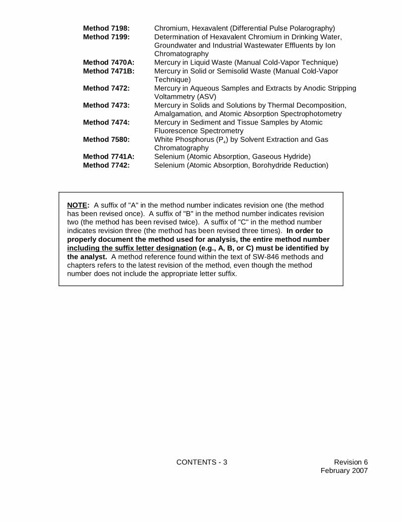
NOTE: A suffix of "A" in the method number indicates revision one (the methodhas been revised once). A suffix of "B" in the method number indicates revisiontwo (the method has been revised twice). A suffix of "C" in the method numberindicates revision three (the method has been revised three times). In order toproperly document the method used for analysis, the entire method numberincluding the suffix letter designation (e.g., A, B, or C) must be identified bythe analyst. A method reference found within the text of SW-846 methods andchapters refers to the latest revision of the method, even though the methodnumber does not include the appropriate letter suffix.
Method 7198: Chromium, Hexavalent (Differential Pulse Polarography)Method 7199: Determination of Hexavalent Chromium in Drinking Water,
Groundwater and Industrial Wastewater Effluents by IonChromatography
Method 7470A: Mercury in Liquid Waste (Manual Cold-Vapor Technique)Method 7471B: Mercury in Solid or Semisolid Waste (Manual Cold-Vapor
Technique)Method 7472: Mercury in Aqueous Samples and Extracts by Anodic Stripping
Voltammetry (ASV)Method 7473: Mercury in Solids and Solutions by Thermal Decomposition,
Amalgamation, and Atomic Absorption SpectrophotometryMethod 7474: Mercury in Sediment and Tissue Samples by Atomic
Fluorescence SpectrometryMethod 7580: White Phosphorus (P4) by Solvent Extraction and Gas
Method 8000B: Determinative Chromatographic SeparationsMethod 8011: 1,2-Dibromoethane and 1,2-Dibromo-3-chloropropane by
Microextraction and Gas ChromatographyMethod 8015C: Nonhalogenated Organics by Gas ChromatographyMethod 8021B: Aromatic and Halogenated Volatiles by Gas Chromatography
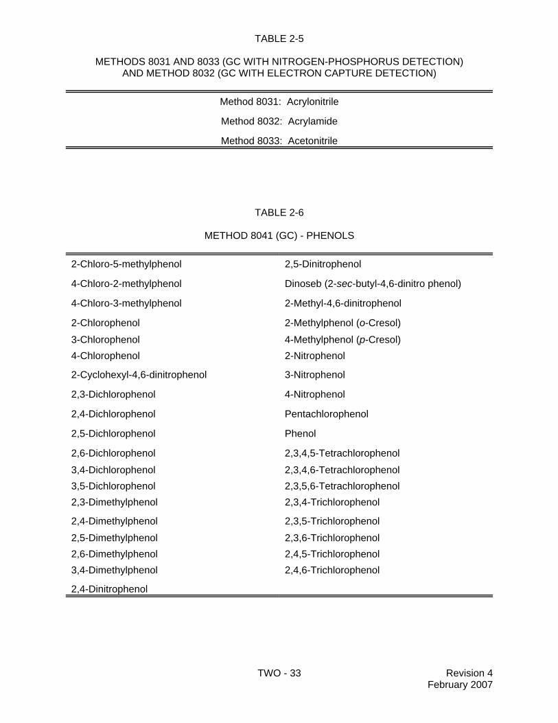
Using Photoionization and/or Electrolytic Conductivity DetectorsMethod 8031: Acrylonitrile by Gas ChromatographyMethod 8032A: Acrylamide by Gas ChromatographyMethod 8033: Acetonitrile by Gas Chromatography with Nitrogen-Phosphorus
DetectionMethod 8041A: Phenols by Gas ChromatographyMethod 8061A: Phthalate Esters by Gas Chromatography with Electron Capture
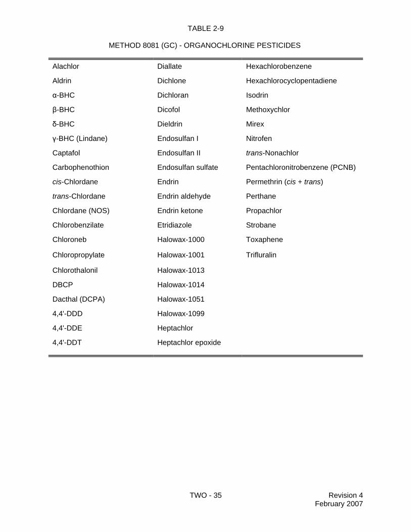
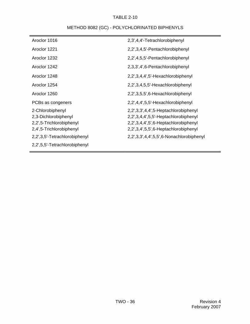
Detection (GC/ECD)Method 8070A: Nitrosamines by Gas ChromatographyMethod 8081B: Organochlorine Pesticides by Gas Chromatography Method 8082A: Polychlorinated Biphenyls (PCBs) by Gas ChromatographyMethod 8085: Compound-independent Elemental Quantitation of Pesticides by
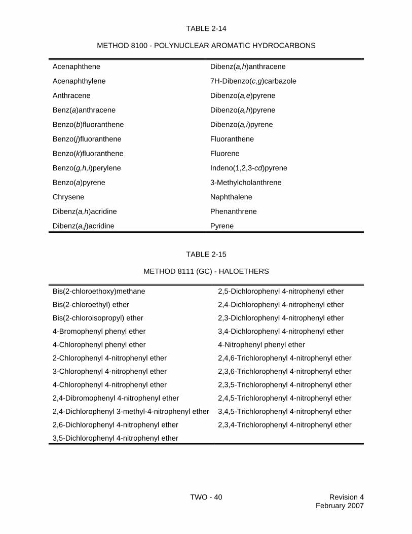
Gas Chromatography with Atomic Emission Detection (GC/AED)Method 8091: Nitroaromatics and Cyclic Ketones by Gas ChromatographyMethod 8095: Explosives by Gas ChromatographyMethod 8100: Polynuclear Aromatic Hydrocarbons
CONTENTS - 6 Revision 6February 2007
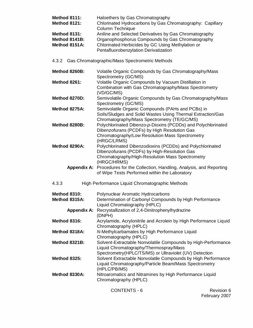
Method 8111: Haloethers by Gas ChromatographyMethod 8121: Chlorinated Hydrocarbons by Gas Chromatography: Capillary
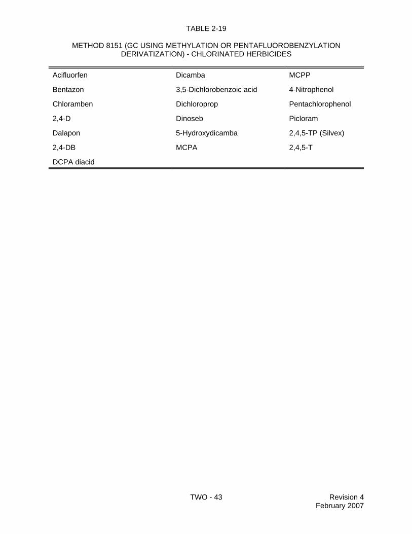
Column TechniqueMethod 8131: Aniline and Selected Derivatives by Gas ChromatographyMethod 8141B: Organophosphorus Compounds by Gas ChromatographyMethod 8151A: Chlorinated Herbicides by GC Using Methylation or
Pentafluorobenzylation Derivatization
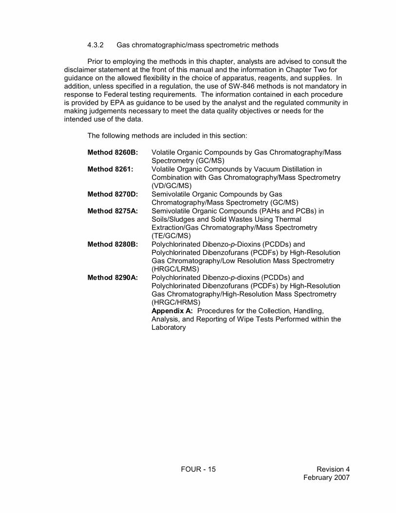
4.3.2 Gas Chromatographic/Mass Spectrometric Methods
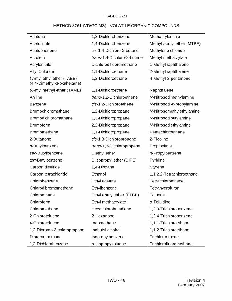
Method 8260B: Volatile Organic Compounds by Gas Chromatography/MassSpectrometry (GC/MS)
Method 8261: Volatile Organic Compounds by Vacuum Distillation inCombination with Gas Chromatography/Mass Spectrometry(VD/GC/MS)
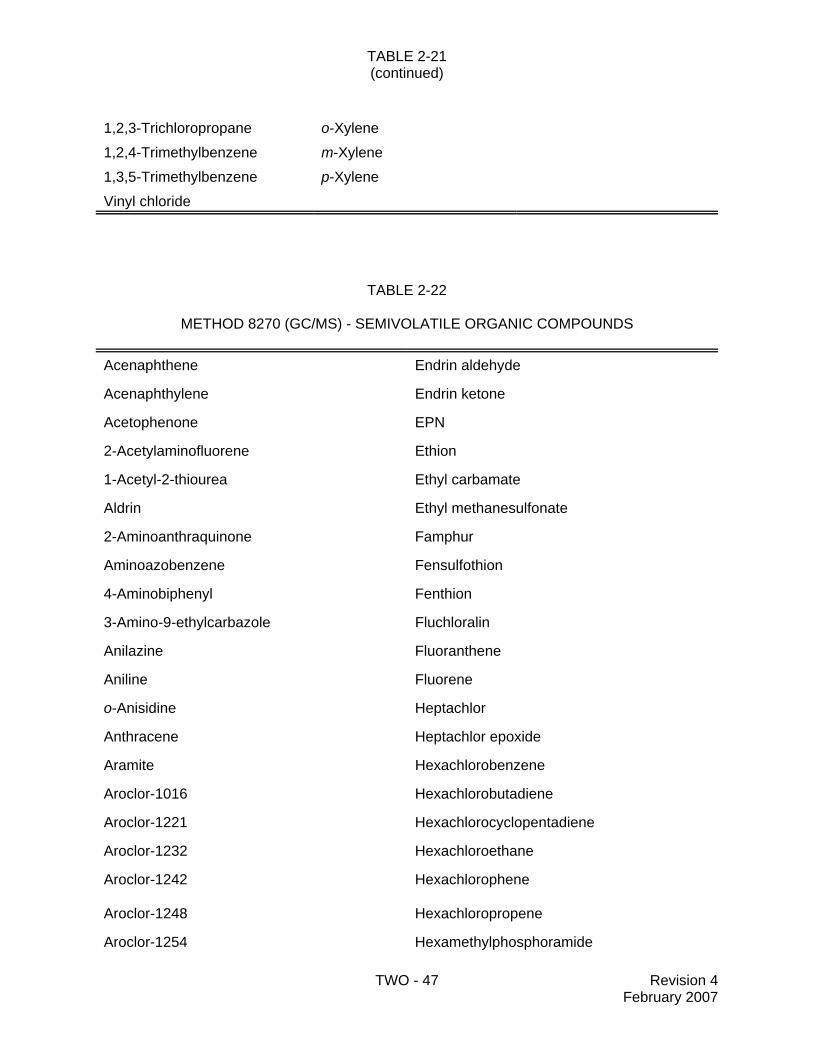
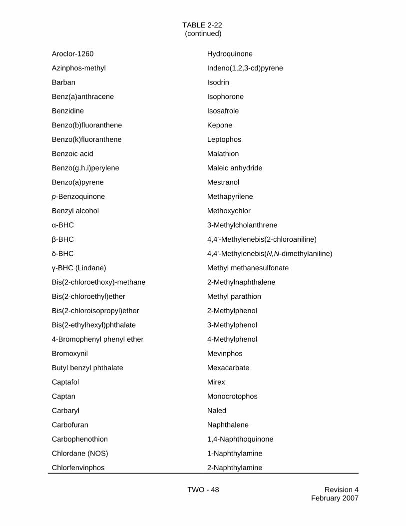
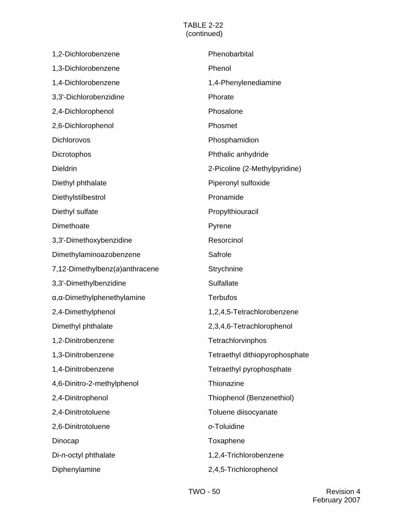
Method 8270D: Semivolatile Organic Compounds by Gas Chromatography/MassSpectrometry (GC/MS)
Method 8275A: Semivolatile Organic Compounds (PAHs and PCBs) inSoils/Sludges and Solid Wastes Using Thermal Extraction/GasChromatography/Mass Spectrometry (TE/GC/MS)
Method 8280B: Polychlorinated Dibenzo-p-Dioxins (PCDDs) and PolychlorinatedDibenzofurans (PCDFs) by High Resolution GasChromatography/Low Resolution Mass Spectrometry(HRGC/LRMS)
Method 8290A: Polychlorinated Dibenzodioxins (PCDDs) and PolychlorinatedDibenzofurans (PCDFs) by High-Resolution GasChromatography/High-Resolution Mass Spectrometry(HRGC/HRMS)
Appendix A: Procedures for the Collection, Handling, Analysis, and Reportingof Wipe Tests Performed within the Laboratory
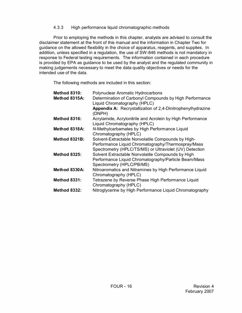
4.3.3 High Performance Liquid Chromatographic Methods
Method 8310: Polynuclear Aromatic HydrocarbonsMethod 8315A: Determination of Carbonyl Compounds by High Performance
Liquid Chromatography (HPLC)Appendix A: Recrystallization of 2,4-Dinitrophenylhydrazine
(DNPH)Method 8316: Acrylamide, Acrylonitrile and Acrolein by High Performance Liquid
Chromatography (HPLC)Method 8318A: N-Methylcarbamates by High Performance Liquid
Chromatography (HPLC)Method 8321B: Solvent-Extractable Nonvolatile Compounds by High-Performance
Liquid Chromatography/Thermospray/MassSpectrometry(HPLC/TS/MS) or Ultraviolet (UV) Detection
Method 8325: Solvent Extractable Nonvolatile Compounds by High PerformanceLiquid Chromatography/Particle Beam/Mass Spectrometry(HPLC/PB/MS)
Method 8330A: Nitroaromatics and Nitramines by High Performance LiquidChromatography (HPLC)
CONTENTS - 7 Revision 6February 2007
Method 8331: Tetrazene by Reverse Phase High Performance LiquidChromatography (HPLC)
Method 8332: Nitroglycerine by High Performance Liquid Chromatography
4.3.4 Infrared Methods
Method 8410: Gas Chromatography/Fourier Transform Infrared (GC/FT-IR)Spectrometry for Semivolatile Organics: Capillary Column
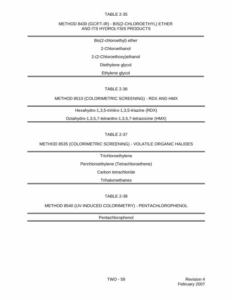
Method 8430: Analysis of Bis(2-chloroethyl) Ether and Hydrolysis Products byDirect Aqueous Injection GC/FT-IR
Method 8440: Total Recoverable Petroleum Hydrocarbons by InfraredSpectrophotometry
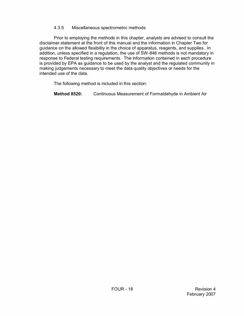
4.3.5 Miscellaneous Spectrometric Methods
Method 8520: Continuous Measurement of Formaldehyde in Ambient Air
4.4 Immunoassay Methods
Method 4000: ImmunoassayMethod 4010A: Screening for Pentachlorophenol by ImmunoassayMethod 4015: Screening for 2,4-Dichlorophenoxyacetic Acid by ImmunoassayMethod 4020: Screening for Polychlorinated Biphenyls by Immunoassay Method 4030: Soil Screening for Petroleum Hydrocarbons by ImmunoassayMethod 4035: Soil Screening for Polynuclear Aromatic Hydrocarbons by
ImmunoassayMethod 4040: Soil Screening for Toxaphene by Immunoassay Method 4041: Soil Screening for Chlordane by Immunoassay Method 4042: Soil Screening for DDT by Immunoassay Method 4050: TNT Explosives in Soil by Immunoassay Method 4051: Hexahydro-1,3,5-trinitro-1,3,5-triazine (RDX) in Soil by
Immunoassay Method 4425: Screening Extracts of Environmental Samples for Planar Organic
Compounds (PAHs, PCBs, PCDDs/PCDFs) by a Reporter Geneon a Human Cell Line
Method 4670: Triazine Herbicides as Atrazine in Water by QuantitativeImmunoassay
CONTENTS - 8 Revision 6February 2007
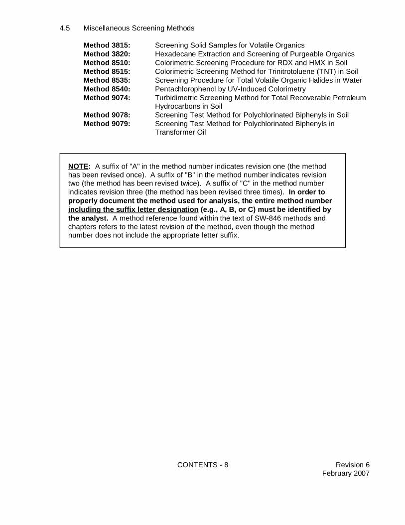
NOTE: A suffix of "A" in the method number indicates revision one (the methodhas been revised once). A suffix of "B" in the method number indicates revisiontwo (the method has been revised twice). A suffix of "C" in the method numberindicates revision three (the method has been revised three times). In order toproperly document the method used for analysis, the entire method numberincluding the suffix letter designation (e.g., A, B, or C) must be identified bythe analyst. A method reference found within the text of SW-846 methods andchapters refers to the latest revision of the method, even though the methodnumber does not include the appropriate letter suffix.
4.5 Miscellaneous Screening Methods
Method 3815: Screening Solid Samples for Volatile OrganicsMethod 3820: Hexadecane Extraction and Screening of Purgeable OrganicsMethod 8510: Colorimetric Screening Procedure for RDX and HMX in SoilMethod 8515: Colorimetric Screening Method for Trinitrotoluene (TNT) in SoilMethod 8535: Screening Procedure for Total Volatile Organic Halides in WaterMethod 8540: Pentachlorophenol by UV-Induced ColorimetryMethod 9074: Turbidimetric Screening Method for Total Recoverable Petroleum
Hydrocarbons in SoilMethod 9078: Screening Test Method for Polychlorinated Biphenyls in SoilMethod 9079: Screening Test Method for Polychlorinated Biphenyls in
Transformer Oil
CONTENTS - 9 Revision 6February 2007
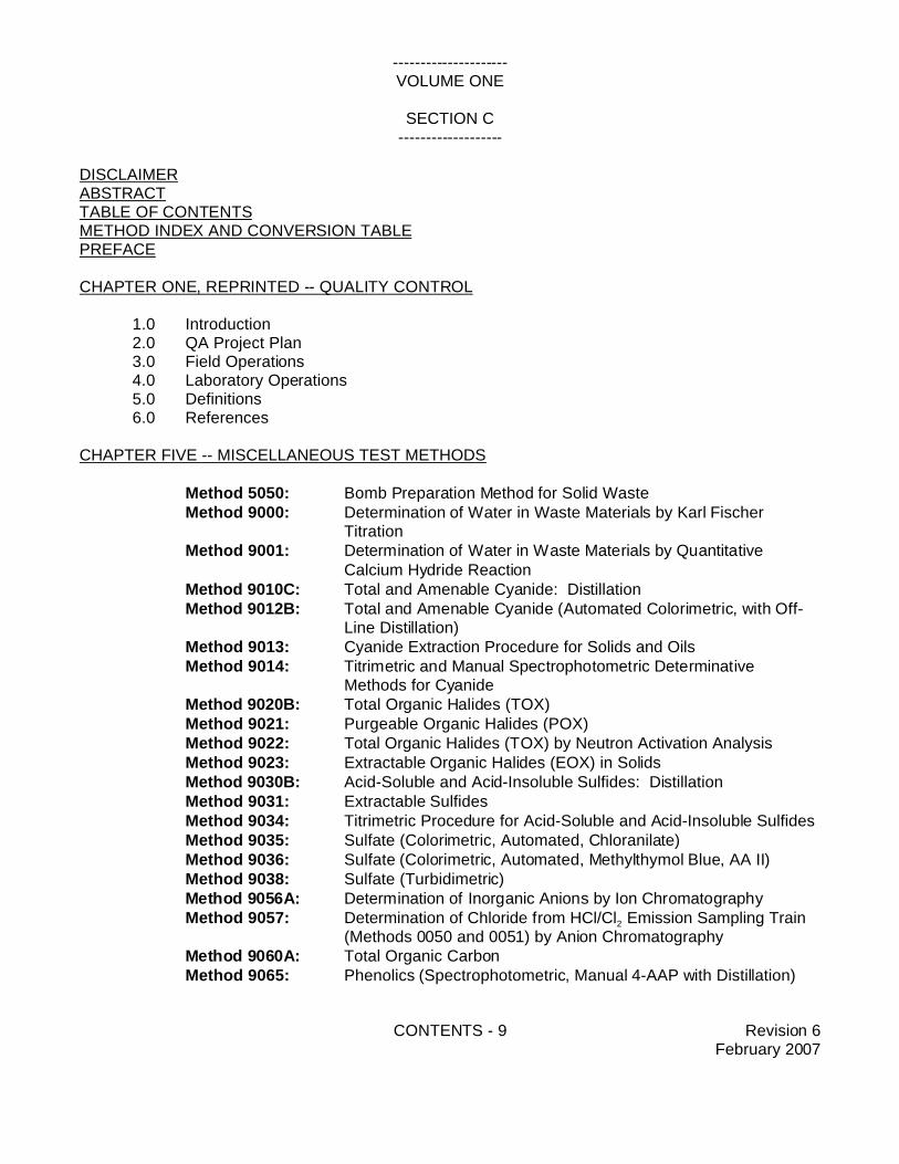
---------------------VOLUME ONE
SECTION C-------------------
DISCLAIMERABSTRACTTABLE OF CONTENTSMETHOD INDEX AND CONVERSION TABLEPREFACE
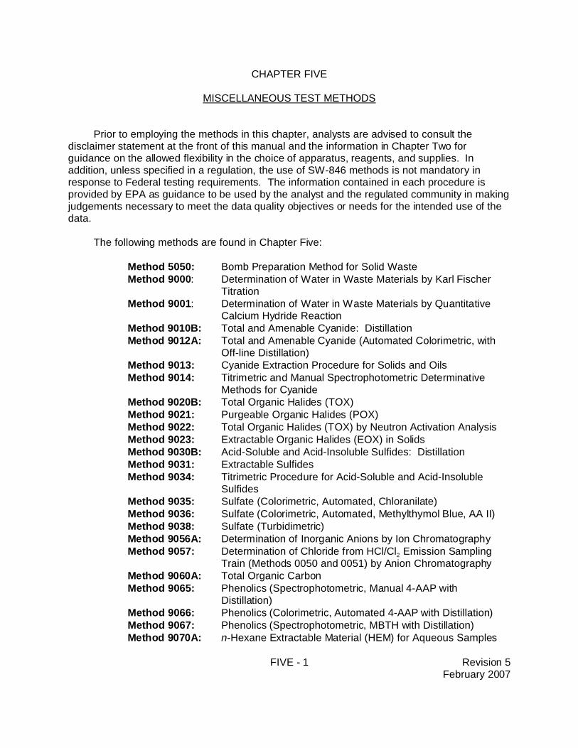
Method 5050: Bomb Preparation Method for Solid WasteMethod 9000: Determination of Water in Waste Materials by Karl Fischer
TitrationMethod 9001: Determination of Water in Waste Materials by Quantitative
Calcium Hydride Reaction Method 9010C: Total and Amenable Cyanide: Distillation Method 9012B: Total and Amenable Cyanide (Automated Colorimetric, with Off-
Line Distillation)Method 9013: Cyanide Extraction Procedure for Solids and OilsMethod 9014: Titrimetric and Manual Spectrophotometric Determinative
Methods for CyanideMethod 9020B: Total Organic Halides (TOX)Method 9021: Purgeable Organic Halides (POX)Method 9022: Total Organic Halides (TOX) by Neutron Activation AnalysisMethod 9023: Extractable Organic Halides (EOX) in SolidsMethod 9030B: Acid-Soluble and Acid-Insoluble Sulfides: DistillationMethod 9031: Extractable SulfidesMethod 9034: Titrimetric Procedure for Acid-Soluble and Acid-Insoluble SulfidesMethod 9035: Sulfate (Colorimetric, Automated, Chloranilate)Method 9036: Sulfate (Colorimetric, Automated, Methylthymol Blue, AA II)Method 9038: Sulfate (Turbidimetric)Method 9056A: Determination of Inorganic Anions by Ion Chromatography Method 9057: Determination of Chloride from HCl/Cl2 Emission Sampling Train
(Methods 0050 and 0051) by Anion ChromatographyMethod 9060A: Total Organic CarbonMethod 9065: Phenolics (Spectrophotometric, Manual 4-AAP with Distillation)
CONTENTS - 10 Revision 6February 2007
Method 9066: Phenolics (Colorimetric, Automated 4-AAP with Distillation)Method 9067: Phenolics (Spectrophotometric, MBTH with Distillation)Method 9070A: n-Hexane Extractable Material (HEM) for Aqueous SamplesMethod 9071B: n-Hexane Extractable Material (HEM) for Sludge, Sediment, and
Solid SamplesMethod 9075: Test Method for Total Chlorine in New and Used Petroleum
Products by X-Ray Fluorescence Spectrometry (XRF)Method 9076: Test Method for Total Chlorine in New and Used Petroleum
Products by Oxidative Combustion and MicrocoulometryMethod 9077: Test Methods for Total Chlorine in New and Used Petroleum
Products (Field Test Kit Methods)Method A: Fixed End Point Test Kit MethodMethod B: Reverse Titration Quantitative End Point Test Kit MethodMethod C: Direct Titration Quantitative End Point Test Kit Method
Method 9131: Total Coliform: Multiple Tube Fermentation TechniqueMethod 9132: Total Coliform: Membrane-Filter TechniqueMethod 9210A: Potentiometric Determination of Nitrate in Aqueous Samples with
an Ion-Selective ElectrodeMethod 9211: Potentiometric Determination of Bromide in Aqueous Samples
with Ion-Selective ElectrodeMethod 9212: Potentiometric Determination of Chloride in Aqueous Samples
with Ion-Selective ElectrodeMethod 9213: Potentiometric Determination of Cyanide in Aqueous Samples and
Distillates with Ion-Selective ElectrodeMethod 9214: Potentiometric Determination of Fluoride in Aqueous Samples
with Ion-Selective ElectrodeMethod 9215: Potentiometric Determination of Sulfide in Aqueous Samples and
Distillates with Ion-Selective ElectrodeMethod 9216: Potentiometric Determination of Nitrite in Aqueous Samples with
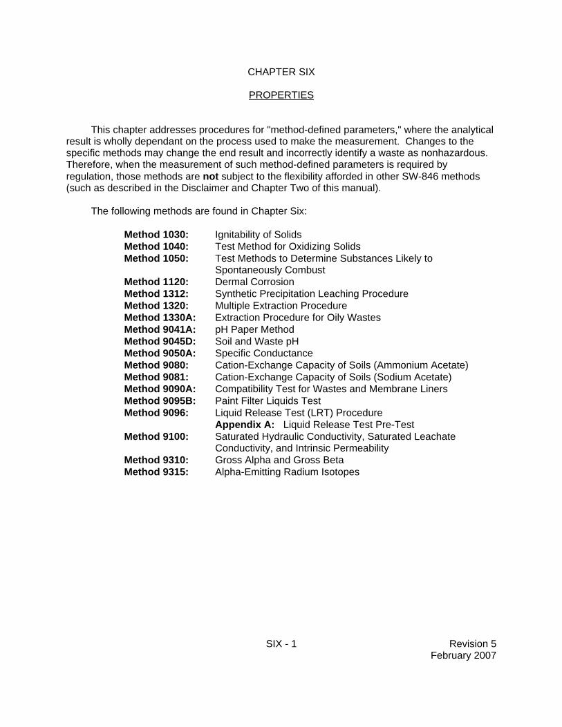
Method 1030: Ignitability of SolidsMethod 1040: Test Method for Oxidizing SolidsMethod 1050: Test Methods to Determine Substances Likely to Spontaneously
CombustMethod 1120: Dermal CorrosionMethod 1312: Synthetic Precipitation Leaching ProcedureMethod 1320: Multiple Extraction ProcedureMethod 1330A: Extraction Procedure for Oily WastesMethod 9041A: pH Paper MethodMethod 9045D: Soil and Waste pHMethod 9050A: Specific Conductance
CONTENTS - 11 Revision 6February 2007
Method 9080: Cation-Exchange Capacity of Soils (Ammonium Acetate)Method 9081: Cation-Exchange Capacity of Soils (Sodium Acetate)Method 9090A: Compatibility Test for Wastes and Membrane LinersMethod 9095B: Paint Filter Liquids TestMethod 9096: Liquid Release Test (LRT) Procedure
Conductivity, and Intrinsic PermeabilityMethod 9310: Gross Alpha and Gross BetaMethod 9315: Alpha-Emitting Radium Isotopes
CONTENTS - 12 Revision 6February 2007
NOTE: A suffix of "A" in the method number indicates revision one (the methodhas been revised once). A suffix of "B" in the method number indicates revisiontwo (the method has been revised twice). A suffix of "C" in the method numberindicates revision three (the method has been revised three times). In order toproperly document the method used for analysis, the entire method numberincluding the suffix letter designation (e.g., A, B, or C) must be identified bythe analyst. A method reference found within the text of SW-846 methods andchapters refers to the latest revision of the method, even though the methodnumber does not include the appropriate letter suffix.
___________________________PART II CHARACTERISTICS
CHAPTER SEVEN -- CHARACTERISTICS INTRODUCTION AND REGULATORY DEFINITIONS
Method 0010: Modified Method 5 Sampling TrainAppendix A: Preparation of XAD-2 Sorbent ResinAppendix B: Total Chromatographable Organic Material Analysis
Method 0011: Sampling for Selected Aldehyde and Ketone Emissions fromStationary Sources
Method 0020: Source Assessment Sampling System (SASS)Method 0023A: Sampling Method for Polychlorinated Dibenzo-p-Dioxins and
Polychlorinated Dibenzofuran Emissions from Stationary SourcesMethod 0030: Volatile Organic Sampling TrainMethod 0031: Sampling Method for Volatile Organic Compounds (SMVOC)Method 0040: Sampling of Principal Organic Hazardous Constituents from
Combustion Sources Using Tedlar® BagsMethod 0050: Isokinetic HCl/Cl2 Emission Sampling TrainMethod 0051: Midget Impinger HCl/Cl2 Emission Sampling TrainMethod 0060: Determination of Metals in Stack EmissionsMethod 0061: Determination of Hexavalent Chromium Emissions from
Stationary SourcesMethod 0100: Sampling for Formaldehyde and Other Carbonyl Compounds in
Indoor AirMethod 25D: Determination of the Volatile Organic Concentration of Waste
Samples
CONTENTS - 14 Revision 6February 2007
Method 25E: Determination of Vapor Phase Organic Concentration in WasteSamples
Method 207: A Method for Measuring Isocyanates in Stationary SourceEmissions
CONTENTS - 15 Revision 6February 2007
NOTE: A suffix of "A" in the method number indicates revision one (the methodhas been revised once). A suffix of "B" in the method number indicates revisiontwo (the method has been revised twice). A suffix of "C" in the method numberindicates revision three (the method has been revised three times). In order toproperly document the method used for analysis, the entire method numberincluding the suffix letter designation (e.g., A, B, or C) must be identified bythe analyst. A method reference found within the text of SW-846 methods andchapters refers to the latest revision of the method, even though the methodnumber does not include the appropriate letter suffix.
____________________PART IV MONITORING
CHAPTER ELEVEN -- GROUND WATER MONITORING
Referral to the EPA Office of Solid Waste guidance document entitled "RCRA Ground-waterMonitoring: Draft Technical Guidance," published in 1992.
CHAPTER TWELVE -- LAND TREATMENT MONITORING
12.1 Background12.2 Treatment Zone12.3 Regulatory Definition12.4 Monitoring and Sampling Strategy12.5 Analysis12.6 References and Bibliography
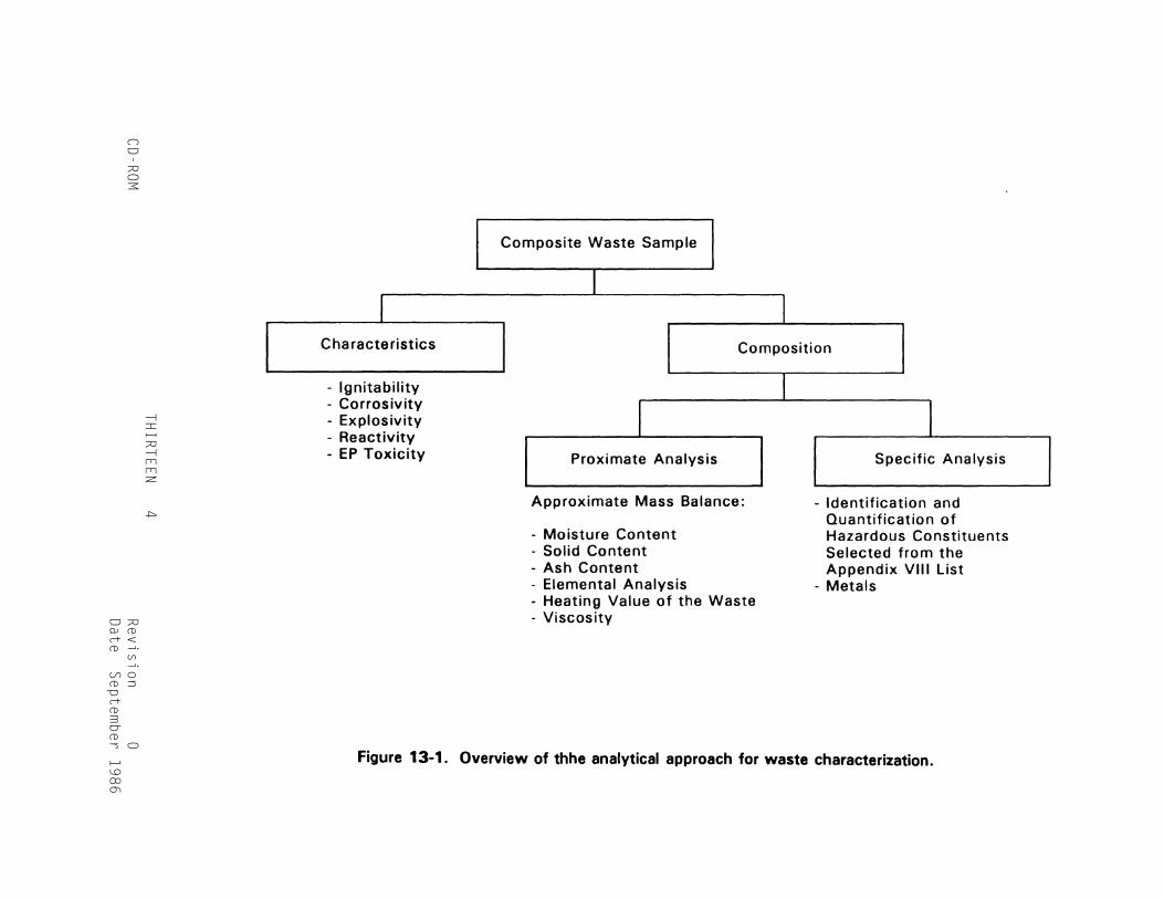
CHAPTER THIRTEEN -- INCINERATION
13.1 Introduction13.2 Regulatory Definition13.3 Waste Characterization Strategy13.4 Stack-Gas Effluent Characterization Strategy13.5 Additional Effluent Characterization Strategy13.6 Selection of Specific Sampling and Analysis Methods13.7 References
METHOD INDEX 1CD-ROM Revision 0
Date September 1986
METHOD INDEX AND CONVERSION TABLE
Method Number, Chapter Number, Method Number, Current RevisionThird Edition Third Edition Second Edition Number
0010 Ten 0010 00020 Ten 0020 00030 Ten 0030 01010 Eight (8.1) 1010 01020 Eight (8.1) 1020 0
1110 Eight (8.2) 1110 01310 Eight (8.4) 1310 01320 Six 1320 01330 Six 1330 03005 Three 3005 0
3010 Three 3010 03020 Three 3020 03040 Three 3040 03050 Three 3050 03500 Four (4.2.1) None (new method) 0
3510 Four (4.2.1) 3510 03520 Four (4.2.1) 3520 03540 Four (4.2.1) 3540 03550 Four (4.2.1) 3550 03580 Four (4.2.1) None (new method) 0
3600 Four (4.2.2) None (new method) 03610 Four (4.2.2) None (new method) 03611 Four (4.2.2) 3570 03620 Four (4.2.2) None (new method) 03630 Four (4.2.2) None (new method) 0
3640 Four (4.2.2) None (new method) 03650 Four (4.2.2) None (new method) 03660 Four (4.2.2) None (new method) 03810 Four (4.4) 5020 03820 Four (4.4) None (new method) 0
5030 Four (4.2.1) 5030 05040 Four (4.2.1) 3720 06010 Three 6010 07000 Three 7000 07020 Three 7020 0
METHOD INDEX 2CD-ROM Revision 0
Date September 1986
METHOD INDEX AND CONVERSION TABLE (Continued)
Method Number, Chapter Number, Method Number, Current RevisionThird Edition Third Edition Second Edition Number
7040 Three 7040 07041 Three 7041 07060 Three 7060 07061 Three 7061 07080 Three 7080 0
7090 Three 7090 07091 Three 7091 07130 Three 7130 07131 Three 7131 07140 Three 7140 0
7190 Three 7190 07191 Three 7191 07195 Three 7195 07196 Three 7196 07197 Three 7197 0
7198 Three 7198 07200 Three 7200 07201 Three 7201 07210 Three 7210 07380 Three 7380 0
7420 Three 7420 07421 Three 7421 07450 Three 7450 07460 Three 7460 07470 Three 7470 0
7471 Three 7471 07480 Three 7480 07481 Three 7481 07520 Three 7520 07550 Three 7550 0
7610 Three 7610 07740 Three 7740 07741 Three 7741 07760 Three 7760 07770 Three 7770 0
METHOD INDEX 3CD-ROM Revision 0
Date September 1986
METHOD INDEX AND CONVERSION TABLE (Continued)
Method Number, Chapter Number, Method Number, Current RevisionThird Edition Third Edition Second Edition Number
7840 Three 7840 07841 Three 7841 07870 Three 7870 07910 Three 7910 07911 Three 7911 0
7950 Three 7950 08000 Four (4.3.1) None (new method) 08010 Four (4.3.1) 8010 08015 Four (4.3.1) 8015 08020 Four (4.3.1) 8020 0
8030 Four (4.3.1) 8030 08040 Four (4.3.1) 8040 08060 Four (4.3.1) 8060 08080 Four (4.3.1) 8080 08090 Four (4.3.1) 8090 0
8100 Four (4.3.1) 8100 0 8120 Four (4.3.1) 8120 0 8140 Four (4.3.1) 8140 0
8150 Four (4.3.1) 8150 08240 Four (4.3.2) 8240 0
8250 Four (4.3.2) 8250 08270 Four (4.3.2) 8270 08280 Four (4.3.2) None (new method) 08310 Four (4.3.3) 8310 09010 Five 9010 0
9020 Five 9020 09022 Five 9022 09030 Five 9030 09035 Five 9035 09036 Five 9036 0
9038 Five 9038 09040 Six 9040 09041 Six 9041 09045 Six 9045 09050 Six 9050 0
METHOD INDEX AND CONVERSION TABLE (Continued)
METHOD INDEX 4CD-ROM Revision 0
Date September 1986
Method Number, Chapter Number, Method Number, Current RevisionThird Edition Third Edition Second Edition Number
9060 Five 9060 09065 Five 9065 09066 Five 9066 09067 Five 9067 09070 Five 9070 0
9071 Five 9071 09080 Six 9080 09081 Six 9081 09090 Six 9090 09095 Six 9095 0
9100 Six 9100 09131 Five 9131 09132 Five 9132 09200 Five 9200 09250 Five 9250 0
9251 Five 9251 09252 Five 9252 09310 Six 9310 09315 Six 9315 09320 Five 9320 0
HCN Test Method Seven HCN Test Method 0H S Test Method Seven H S Test Method 02 2
STATUS TABLES FOR SW-846, THIRD EDITION FINAL UPDATES I, II, IIA, IIB, III, IIIA, IIIB AND IV PLUS OTHER NEW AND REVISED SW-846 METHODS AT THE OSW METHODS WEB SITE
REVISED MARCH 2009
HOW TO USE THIS DOCUMENT
This document provides historical information regarding EPA-published SW-846 methods and chapters. It contains two status tables, namely; the "SW-846 Method Status Table," which is a listing of SW-846 methods; and the "Status Table for SW-846 Chapter Text and Other Documents," which lists all other documents in SW-846 (e.g., chapters).
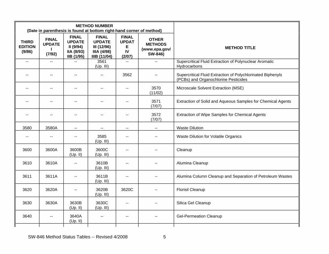
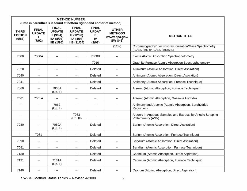
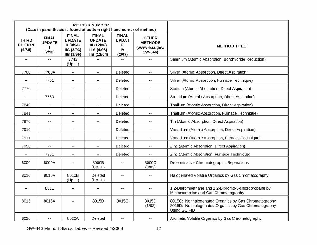
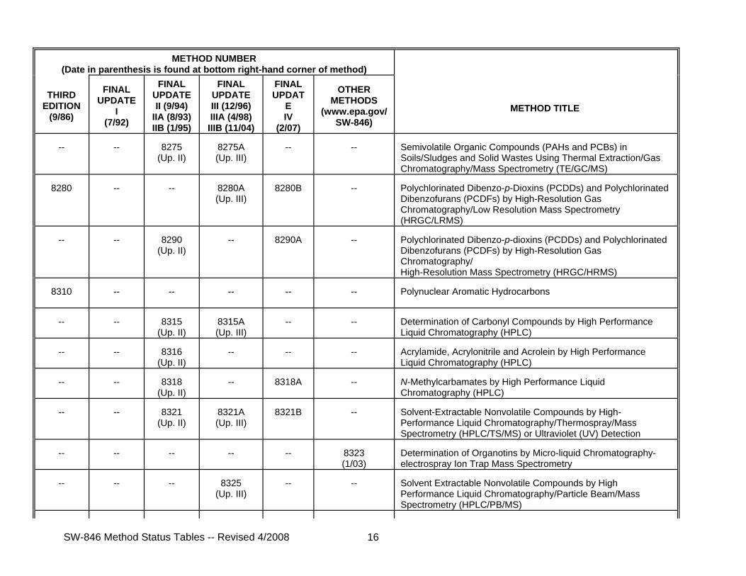
Use the "SW-846 Method Status Table" as a reference guide to identify the historical and latest versions of SW-846 methods. Methods in this status table are listed sequentially by method number. The column showing "Other Methods" includes those new and revised methods that appear as new SW-846 methods at EPA's Office of Resource Conservation and Recovery Methods Team internet site, http://www.epa.gov/SW-846/. An integrated version of the manual through Final Update IV is also available at the Methods Team internet site.
Methods that have "deleted" as the latest status are those methods that have been removed from SW-846 for various reasons, and you will not find that method at the Methods Team web site. See the associated update rulemakings or notices for an explanation regarding why a method was deleted from SW-846.
Letter suffixes (e.g, A, B, C) to a method number identify the revision status of the method. New methods, i.e., Revision 0 methods, do not
have a letter suffix. A suffix of “A” in a method number indicates Revision 1 (the method has been revised once and distributed as final), a suffix of “B” indicates Revision 2, and so on. The date in the footer of an SW-846 method (e.g., February 2007 in the bottom right corner of Final Update IV methods) is the approximate date for when the method was last revised.
Use the "Status Table for SW-846 Chapter Text and Other Documents" as a reference guide to identify the historical and latest versions of chapters and other SW-846 documents (e.g., the Disclaimer).
With the publication of the final Methods Innovation Rule, SW-846 and its methods are no longer required in general by any RCRA regulation. See 40 CFR 260.11(a)(11) for a listing of those SW-846 methods that may be still required by the RCRA regulations for the analysis of method-defined parameters.
Do not use a status table as a guide for putting together a paper version of SW-846. Refer to the "Table of Contents" of the update for the order in which chapters and methods should appear in SW-846.
SW-846 Method Status Tables -- Revised 4/2008 1
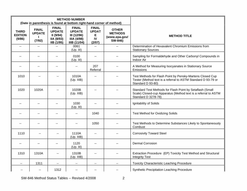
SW-846 METHOD STATUS TABLE
METHOD NUMBER
(Date in parenthesis is found at bottom right-hand corner of method)
THIRD EDITION
(9/86)
FINAL
UPDATE I
(7/92)
FINAL
UPDATE II (9/94)
IIA (8/93) IIB (1/95)
FINAL
UPDATE III (12/96) IIIA (4/98) IIIB (11/04)
FINAL UPDAT
E IV
(2/07)
OTHER
METHODS (www.epa.gov/
SW-846)
METHOD TITLE
0010
--
--
--
--
--
Modified Method 5 Sampling Train
--
--
--
0011
(Up. III)
--
--
Sampling for Selected Aldehyde and Ketone Emissions from Stationary Sources
0020
--
--
--
--
--
Source Assessment Sampling System (SASS)
--
--
--
0023A (Up. III)
--
--
Sampling Method for Polychlorinated Dibenzo-p-Dioxins and Polychlorinated Dibenzofuran Emissions from Stationary Sources (Note: This method is a revision of Method 23, 40 CFR Part 60.)
--
--
--
--
25D
Referral
--
Determination of the Volatile Organic Concentration of Waste Samples
--
--
--
--
25E
Referral
--
Determination of Vapor Phase Organic Concentration in Waste Samples
0030
--
--
--
--
--
Volatile Organic Sampling Train
--
--
--
0031
(Up. III)
--
--
Sampling Method for Volatile Organic Compounds (SMVOC)
--
--
--
0040
(Up. III)
--
--
Sampling of Principal Organic Hazardous Constituents from Combustion Sources Using Tedlar7 Bags
--
--
--
0050
(Up. III)
--
--
Isokinetic HCl/Cl2 Emission Sampling Train
--
--
--
0051
(Up. III)
--
--
Midget Impinger HCl/Cl2 Emission Sampling Train
--
--
--
0060
(Up. III)
--
--
Determination of Metals in Stack Emissions
SW-846 Method Status Tables -- Revised 4/2008 2
METHOD NUMBER
(Date in parenthesis is found at bottom right-hand corner of method)
THIRD EDITION
(9/86)
FINAL
UPDATE I
(7/92)
FINAL
UPDATE II (9/94)
IIA (8/93) IIB (1/95)
FINAL
UPDATE III (12/96) IIIA (4/98) IIIB (11/04)
FINAL UPDAT
E IV
(2/07)
OTHER
METHODS (www.epa.gov/
SW-846)
METHOD TITLE
-- -- -- 0061 (Up. III)
-- -- Determination of Hexavalent Chromium Emissions from Stationary Sources
--
--
--
0100
(Up. III)
--
--
Sampling for Formaldehyde and Other Carbonyl Compounds in Indoor Air
--
--
--
--
207
Referral
--
A Method for Measuring Isocyanates in Stationary Source Emissions
1010
--
--
1010A
(Up. IIIB)
--
--
Test Methods for Flash Point by Pensky-Martens Closed Cup Tester (Method text is a referral to ASTM Standard D 93-79 or Standard D 93-80)
1020
1020A
--
1020B
(Up. IIIB)
--
--
Standard Test Methods for Flash Point by Setaflash (Small Scale) Closed-cup Apparatus (Method text is a referral to ASTM Standard D 3278-78)
--
--
--
1030
(Up. III)
--
--
Ignitability of Solids
--
--
--
--
1040
--
Test Method for Oxidizing Solids
--
--
--
--
1050
--
Test Methods to Determine Substances Likely to Spontaneously Combust
1110
--
--
1110A
(Up. IIIB)
--
--
Corrosivity Toward Steel
--
--
--
1120
(Up. III)
--
--
Dermal Corrosion
1310
1310A
--
1310B
(Up. IIIB)
--
--
Extraction Procedure (EP) Toxicity Test Method and Structural Integrity Test
--
1311
--
--
--
--
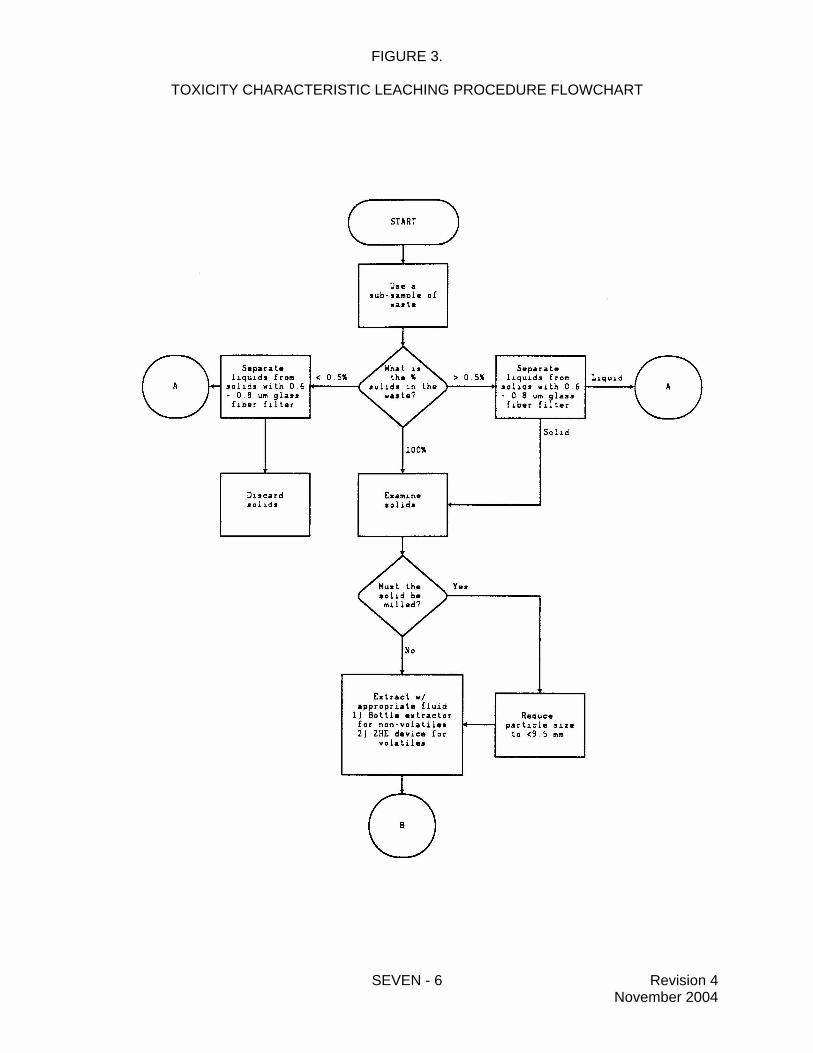
Toxicity Characteristic Leaching Procedure
--
--
1312
--
--
--
Synthetic Precipitation Leaching Procedure
SW-846 Method Status Tables -- Revised 4/2008 3
METHOD NUMBER
(Date in parenthesis is found at bottom right-hand corner of method)
THIRD EDITION
(9/86)
FINAL
UPDATE I
(7/92)
FINAL
UPDATE II (9/94)
IIA (8/93) IIB (1/95)
FINAL
UPDATE III (12/96) IIIA (4/98) IIIB (11/04)
FINAL UPDAT
E IV
(2/07)
OTHER
METHODS (www.epa.gov/
SW-846)
METHOD TITLE
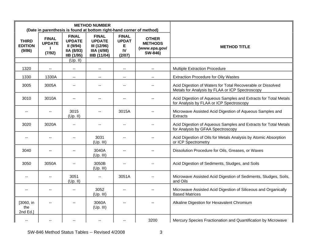
(Up. II)
1320
--
--
--
--
-- Multiple Extraction Procedure
1330
1330A
--
--
--
--
Extraction Procedure for Oily Wastes
3005
3005A
--
--
--
--
Acid Digestion of Waters for Total Recoverable or Dissolved Metals for Analysis by FLAA or ICP Spectroscopy
3010
3010A
--
--
--
--
Acid Digestion of Aqueous Samples and Extracts for Total Metals for Analysis by FLAA or ICP Spectroscopy
--
--
3015
(Up. II)
--
3015A
--
Microwave Assisted Acid Digestion of Aqueous Samples and Extracts
3020
3020A
--
--
--
--
Acid Digestion of Aqueous Samples and Extracts for Total Metals for Analysis by GFAA Spectroscopy
--
--
--
3031
(Up. III)
--
--
Acid Digestion of Oils for Metals Analysis by Atomic Absorption or ICP Spectrometry
3040
--
--
3040A (Up. III)
--
--
Dissolution Procedure for Oils, Greases, or Waxes
3050
3050A
--
3050B (Up. III)
--
--
Acid Digestion of Sediments, Sludges, and Soils
--
--
3051
(Up. II)
--
3051A
--
Microwave Assisted Acid Digestion of Sediments, Sludges, Soils, and Oils
--
--
--
3052
(Up. III)
--
--
Microwave Assisted Acid Digestion of Siliceous and Organically Based Matrices
[3060, in
the 2nd Ed.]
--
--
3060A (Up. III)
--
--
Alkaline Digestion for Hexavalent Chromium
--
--
--
--
--
3200 Mercury Species Fractionation and Quantification by Microwave
SW-846 Method Status Tables -- Revised 4/2008 4
METHOD NUMBER
(Date in parenthesis is found at bottom right-hand corner of method)
Extraction of Semivolatile Analytes Collected Using Method 0010 (Modified Method 5 Sampling Train)
--
--
--
3545
(Up. III)
3545A
--
Pressurized Fluid Extraction (PFE)
--
--
--
--
3546
--
Microwave Extraction
3550
--
3550A (Up. II)
3550B (Up. III)
3550C
--
Ultrasonic Extraction
--
--
--
3560
(Up. III)
--
--
Supercritical Fluid Extraction of Total Recoverable Petroleum Hydrocarbons
SW-846 Method Status Tables -- Revised 4/2008 5
METHOD NUMBER
(Date in parenthesis is found at bottom right-hand corner of method)
THIRD EDITION
(9/86)
FINAL
UPDATE I
(7/92)
FINAL
UPDATE II (9/94)
IIA (8/93) IIB (1/95)
FINAL
UPDATE III (12/96) IIIA (4/98) IIIB (11/04)
FINAL UPDAT
E IV
(2/07)
OTHER
METHODS (www.epa.gov/
SW-846)
METHOD TITLE
-- -- -- 3561 (Up. III)
-- -- Supercritical Fluid Extraction of Polynuclear Aromatic Hydrocarbons
--
--
--
--
3562
--
Supercritical Fluid Extraction of Polychlorinated Biphenyls (PCBs) and Organochlorine Pesticides
--
--
--
--
--
3570
(11/02)
Microscale Solvent Extraction (MSE)
--
--
--
--
--
3571 (7/07)
Extraction of Solid and Aqueous Samples for Chemical Agents
--
--
--
--
--
3572 (7/07)
Extraction of Wipe Samples for Chemical Agents
3580
3580A
--
--
--
--
Waste Dilution
--
--
--
3585
(Up. III)
--
--
Waste Dilution for Volatile Organics
3600
3600A
3600B (Up. II)
3600C (Up. III)
--
--
Cleanup
3610
3610A
--
3610B (Up. III)
--
--
Alumina Cleanup
3611
3611A
--
3611B (Up. III)
--
--
Alumina Column Cleanup and Separation of Petroleum Wastes
3620
3620A
--
3620B (Up. III)
3620C
--
Florisil Cleanup
3630
3630A
3630B (Up. II)
3630C (Up. III)
--
--
Silica Gel Cleanup
3640
--
3640A (Up. II)
--
--
--
Gel-Permeation Cleanup
SW-846 Method Status Tables -- Revised 4/2008 6
METHOD NUMBER
(Date in parenthesis is found at bottom right-hand corner of method)
THIRD EDITION
(9/86)
FINAL
UPDATE I
(7/92)
FINAL
UPDATE II (9/94)
IIA (8/93) IIB (1/95)
FINAL
UPDATE III (12/96) IIIA (4/98) IIIB (11/04)
FINAL UPDAT
E IV
(2/07)
OTHER
METHODS (www.epa.gov/
SW-846)
METHOD TITLE
3650 3650A -- 3650B (Up. III)
-- -- Acid-Base Partition Cleanup
3660
3660A
--
3660B (Up. III)
--
--
Sulfur Cleanup
--
--
3665
(Up. II)
3665A (Up. III)
--
--
Sulfuric Acid/Permanganate Cleanup
3810
--
--
--
Deleted
--
Headspace
--
--
--
--
3815
--
Screening Solid Samples for Volatile Organics
3820
--
--
--
--
--
Hexadecane Extraction and Screening of Purgeable Organics
--
--
--
4000
(Up. III)
--
--
Immunoassay
--
--
4010
(Up. IIA)
4010A (Up. III)
--
--
Screening for Pentachlorophenol by Immunoassay
--
--
--
4015
(Up. III)
--
--
Screening for 2,4-Dichlorophenoxyacetic Acid by Immunoassay
--
--
--
4020
(Up. III)
--
--
Screening for Polychlorinated Biphenyls by Immunoassay
--
--
--
--
--
4025
(10/02)
Screening for Polychlorinated Dibenzodioxins and Polychlorinated Dibenzofurans (PCDD/Fs) by Immunoassay
--
--
--
4030
(Up. III)
--
--
Soil Screening for Petroleum Hydrocarbons by Immunoassay
--
--
--
4035
(Up. III)
--
--
Soil Screening for Polynuclear Aromatic Hydrocarbons by Immunoassay
--
--
--
4040
(Up. III)
--
--
Soil Screening for Toxaphene by Immunoassay
SW-846 Method Status Tables -- Revised 4/2008 7
METHOD NUMBER
(Date in parenthesis is found at bottom right-hand corner of method)
THIRD EDITION
(9/86)
FINAL
UPDATE I
(7/92)
FINAL
UPDATE II (9/94)
IIA (8/93) IIB (1/95)
FINAL
UPDATE III (12/96) IIIA (4/98) IIIB (11/04)
FINAL UPDAT
E IV
(2/07)
OTHER
METHODS (www.epa.gov/
SW-846)
METHOD TITLE
--
--
--
4041
(Up. III)
--
--
Soil Screening for Chlordane by Immunoassay
--
--
--
4042
(Up. III)
--
--
Soil Screening for DDT by Immunoassay
--
--
--
4050
(Up. III)
--
--
TNT Explosives in Soil by Immunoassay
--
--
--
4051
(Up. III)
--
--
Hexahydro-1,3,5-trinitro-1,3,5-triazine (RDX) in Soil by Immunoassay
--
--
--
--
4425
--
Screening Extracts of Environmental Samples for Planar Organic Compounds (PAHs, PCBs, PCDDs/PCDFs) by a Reporter Gene on a Human Cell Line
--
--
--
--
--
4430
(12/2007)
Screening for Polychlorinated Dibenzo-p-dioxins and Furans (PCDD/Fs) by Aryl Hydrocarbon-receptor PCR Assay
--
--
--
--
--
4435
(2/2008)
Method for Toxic Equivalents (TEQs) Determinations for Dioxin-like Chemical Activity with the Calux7 Bioassay
--
--
--
--
4670
--
Triazine Herbicides as Atrazine in Water by Quantitative Immunoassay
--
--
--
5000
(Up. III)
--
--
Sample Preparation for Volatile Organic Compounds
--
--
--
5021
(Up. III)
--
5021A (6/03)
5021: Volatile Organic Compounds in Soils and Other Solid Sample Matrices Using Equilibrium Headspace Analysis 5021A: Volatile Organic Compounds in Various Sample Matrices Using Equilibrium Headspace Analysis
5030
5030A
--
5030B (Up. III)
--
5030C (5/03)
Purge-and-Trap for Aqueous Samples
SW-846 Method Status Tables -- Revised 4/2008 8
METHOD NUMBER
(Date in parenthesis is found at bottom right-hand corner of method)
THIRD EDITION
(9/86)
FINAL
UPDATE I
(7/92)
FINAL
UPDATE II (9/94)
IIA (8/93) IIB (1/95)
FINAL
UPDATE III (12/96) IIIA (4/98) IIIB (11/04)
FINAL UPDAT
E IV
(2/07)
OTHER
METHODS (www.epa.gov/
SW-846)
METHOD TITLE
-- -- -- 5031 (Up. III)
-- -- Volatile, Nonpurgeable, Water-Soluble Compounds by Azeotropic Distillation
--
--
--
5032
(Up. III)
--
--
Volatile Organic Compounds by Vacuum Distillation
--
--
--
5035
(Up. III)
--
5035A (7/02)
Closed-System Purge-and-Trap and Extraction for Volatile Organics in Soil and Waste Samples
5040
--
5040A (Up. II)
Deleted (Up. III)
--
--
Analysis of Sorbent Cartridges from Volatile Organic Sampling Train (VOST): Gas Chromatography/Mass Spectrometry Technique
--
--
5041
(Up. II)
5041A (Up. III)
--
--
Analysis for Desorption of Sorbent Cartridges from Volatile Organic Sampling Train (VOST)
Halogenated Volatile Organics by Gas Chromatography
--
8011
--
--
--
--
1,2-Dibromoethane and 1,2-Dibromo-3-chloropropane by Microextraction and Gas Chromatography
8015
8015A
--
8015B
8015C
8015D (6/03)
8015C: Nonhalogenated Organics by Gas Chromatography 8015D: Nonhalogenated Organics by Gas Chromatography Using GC/FID
8020
--
8020A
Deleted
--
--
Aromatic Volatile Organics by Gas Chromatography
SW-846 Method Status Tables -- Revised 4/2008 13
METHOD NUMBER
(Date in parenthesis is found at bottom right-hand corner of method)
THIRD EDITION
(9/86)
FINAL
UPDATE I
(7/92)
FINAL
UPDATE II (9/94)
IIA (8/93) IIB (1/95)
FINAL
UPDATE III (12/96) IIIA (4/98) IIIB (11/04)
FINAL UPDAT
E IV
(2/07)
OTHER
METHODS (www.epa.gov/
SW-846)
METHOD TITLE
(Up. II) (Up. III)
--
8021
8021A (Up. II)
8021B (Up. III)
--
--
Aromatic and Halogenated Volatiles by Gas Chromatography Using Photoionization and/or Electrolytic Conductivity Detectors
8030
8030A
--
Deleted (Up. III)
--
--
Acrolein and Acrylonitrile by Gas Chromatography
--
--
8031
(Up. II)
--
--
--
Acrylonitrile by Gas Chromatography
--
--
8032
(Up. II)
8032A (Up. III)
--
--
Acrylamide by Gas Chromatography
--
--
--
8033
(Up. III)
--
--
Acetonitrile by Gas Chromatography with Nitrogen-Phosphorus Detection
8040
8040A
--
Deleted (Up. III)
--
--
Phenols by Gas Chromatography
--
--
--
8041
(Up. III)
8041A
--
Phenols by Gas Chromatography
8060
--
--
Deleted (Up. III)
--
--
Phthalate Esters
--
--
8061
(Up. II)
8061A (Up. III)
--
--
Phthalate Esters by Gas Chromatography with Electron Capture Detection (GC/ECD)
--
8070
--
8070A (Up. III)
--
--
Nitrosamines by Gas Chromatography
8080
--
8080A (Up. II)
Deleted (Up. III)
--
--
Organochlorine Pesticides and Polychlorinated Biphenyls by Gas Chromatography
--
--
8081
(Up. II)
8081A (Up. III)
8081B
--
Organochlorine Pesticides by Gas Chromatography
SW-846 Method Status Tables -- Revised 4/2008 14
METHOD NUMBER
(Date in parenthesis is found at bottom right-hand corner of method)
THIRD EDITION
(9/86)
FINAL
UPDATE I
(7/92)
FINAL
UPDATE II (9/94)
IIA (8/93) IIB (1/95)
FINAL
UPDATE III (12/96) IIIA (4/98) IIIB (11/04)
FINAL UPDAT
E IV
(2/07)
OTHER
METHODS (www.epa.gov/
SW-846)
METHOD TITLE
--
--
--
8082
(Up. III)
8082A
--
Polychlorinated Biphenyls (PCBs) by Gas Chromatography
8085
--
Compound-independent Elemental Quantitation of Pesticides by Gas Chromatography with Atomic Emission Detection (GC/AED)
8090
--
--
Deleted (Up. III)
--
--
Nitroaromatics and Cyclic Ketones
--
--
--
8091
(Up. III)
--
--
Nitroaromatics and Cyclic Ketones by Gas Chromatography
--
--
--
--
8095
--
Explosives by Gas Chromatography
8100
--
--
--
--
--
Polynuclear Aromatic Hydrocarbons
--
8110
--
Deleted (Up. III)
--
--
Haloethers by Gas Chromatography
--
--
--
8111
(Up. III)
--
--
Haloethers by Gas Chromatography
8120
--
8120A (Up. II)
Deleted (Up. III)
--
--
Chlorinated Hydrocarbons by Gas Chromatography
--
--
8121
(Up. II)
--
--
--
Chlorinated Hydrocarbons by Gas Chromatography: Capillary Column Technique
--
--
--
8131
(Up. III)
--
--
Aniline and Selected Derivatives by Gas Chromatography
8140
--
--
Deleted (Up. III)
--
--
Organophosphorus Pesticides
--
8141
8141A (Up. II)
--
8141B
--
Organophosphorus Compounds by Gas Chromatography
SW-846 Method Status Tables -- Revised 4/2008 15
METHOD NUMBER
(Date in parenthesis is found at bottom right-hand corner of method)
THIRD EDITION
(9/86)
FINAL
UPDATE I
(7/92)
FINAL
UPDATE II (9/94)
IIA (8/93) IIB (1/95)
FINAL
UPDATE III (12/96) IIIA (4/98) IIIB (11/04)
FINAL UPDAT
E IV
(2/07)
OTHER
METHODS (www.epa.gov/
SW-846)
METHOD TITLE
8150 8150A 8150B (Up. II)
Deleted (Up. III)
-- -- Chlorinated Herbicides by Gas Chromatography
--
--
8151
(Up. II)
8151A (Up. III)
--
--
Chlorinated Herbicides by GC Using Methylation or Pentafluorobenzylation Derivatization
--
--
--
--
--
8170
(7/2007)
Assay of Chemical Agents in Solid and Aqueous Samples by Gas Chromatography/Flame Photometric (GC/FPD) Detection
8240
8240A
8240B (Up. II)
Deleted (Up. III)
--
--
Volatile Organic Compounds by Gas Chromatography/Mass Spectrometry (GC/MS)
8250
--
8250A (Up. II)
Deleted (Up. III)
--
--
Semivolatile Organic Compounds by Gas Chromatography/Mass Spectrometry (GC/MS)
--
8260
8260A (Up. II)
8260B (Up. III)
--
8260C (8/06)
Volatile Organic Compounds by Gas Chromatography/Mass Spectrometry (GC/MS)
--
--
--
--
8261
8261A (10/06)
Volatile Organic Compounds by Vacuum Distillation in Combination with Gas Chromatography/Mass Spectrometry (VD/GC/MS)
--
--
--
--
--
8265 (3/02)
Volatile Organic Compounds in Water, Soil, Soil Gas and Air by Direct Sampling Ion Trap Mass Spectrometry (DSITMS)
8270
8270A
8270B (Up. II)
8270C (Up. III)
8270D
--
Semivolatile Organic Compounds by Gas Chromatography/Mass Spectrometry (GC/MS)
--
--
--
--
--
8271 (7/07)
Assay of Chemical Agents in Solid and Aqueous Samples by Gas Chromatography/Mass Spectrometry/Electron Impact (GC/MS/EI)
--
--
--
--
--
8272
(12/07)
Parent and Alkyl Polycyclic Aromatics in Sediment Pore Water by Solid-phase Microextraction and Gas Chromatography/Mass Spectrometry in Selected Ion Monitoring Mode
SW-846 Method Status Tables -- Revised 4/2008 16
METHOD NUMBER
(Date in parenthesis is found at bottom right-hand corner of method)
THIRD EDITION
(9/86)
FINAL
UPDATE I
(7/92)
FINAL
UPDATE II (9/94)
IIA (8/93) IIB (1/95)
FINAL
UPDATE III (12/96) IIIA (4/98) IIIB (11/04)
FINAL UPDAT
E IV
(2/07)
OTHER
METHODS (www.epa.gov/
SW-846)
METHOD TITLE
--
--
8275
(Up. II)
8275A (Up. III)
--
--
Semivolatile Organic Compounds (PAHs and PCBs) in Soils/Sludges and Solid Wastes Using Thermal Extraction/Gas Chromatography/Mass Spectrometry (TE/GC/MS)
8280
--
--
8280A (Up. III)
8280B
--
Polychlorinated Dibenzo-p-Dioxins (PCDDs) and Polychlorinated Dibenzofurans (PCDFs) by High-Resolution Gas Chromatography/Low Resolution Mass Spectrometry (HRGC/LRMS)
--
--
8290
(Up. II)
--
8290A
--
Polychlorinated Dibenzo-p-dioxins (PCDDs) and Polychlorinated Dibenzofurans (PCDFs) by High-Resolution Gas Chromatography/ High-Resolution Mass Spectrometry (HRGC/HRMS)
8310
--
--
--
--
--
Polynuclear Aromatic Hydrocarbons
--
--
8315
(Up. II)
8315A (Up. III)
--
--
Determination of Carbonyl Compounds by High Performance Liquid Chromatography (HPLC)
--
--
8316
(Up. II)
--
--
--
Acrylamide, Acrylonitrile and Acrolein by High Performance Liquid Chromatography (HPLC)
--
--
8318
(Up. II)
--
8318A
--
N-Methylcarbamates by High Performance Liquid Chromatography (HPLC)
--
--
8321
(Up. II)
8321A (Up. III)
8321B
--
Solvent-Extractable Nonvolatile Compounds by High-Performance Liquid Chromatography/Thermospray/Mass Spectrometry (HPLC/TS/MS) or Ultraviolet (UV) Detection
--
--
--
--
--
8323 (1/03)
Determination of Organotins by Micro-liquid Chromatography-electrospray Ion Trap Mass Spectrometry
--
--
--
8325
(Up. III)
--
--
Solvent Extractable Nonvolatile Compounds by High Performance Liquid Chromatography/Particle Beam/Mass Spectrometry (HPLC/PB/MS)
SW-846 Method Status Tables -- Revised 4/2008 17
METHOD NUMBER
(Date in parenthesis is found at bottom right-hand corner of method)
THIRD EDITION
(9/86)
FINAL
UPDATE I
(7/92)
FINAL
UPDATE II (9/94)
IIA (8/93) IIB (1/95)
FINAL
UPDATE III (12/96) IIIA (4/98) IIIB (11/04)
FINAL UPDAT
E IV
(2/07)
OTHER
METHODS (www.epa.gov/
SW-846)
METHOD TITLE
-- -- 8330 (Up. II)
-- 8330A 8330B (10/06)
Nitroaromatics and Nitramines by High Performance Liquid Chromatography (HPLC)
--
--
8331
(Up. II)
--
--
--
Tetrazene by Reverse Phase High Performance Liquid Chromatography (HPLC)
--
--
--
8332
(Up. III)
--
--
Nitroglycerine by High Performance Liquid Chromatography
--
--
8410
(Up. II)
--
--
--
Gas Chromatography/Fourier Transform Infrared (GC/FT-IR) Spectrometry for Semivolatile Organics: Capillary Column
--
--
--
8430
(Up. III)
--
--
Analysis of Bis(2-chloroethyl) Ether and Hydrolysis Products by Direct Aqueous Injection GC/FT-IR
--
--
--
8440
(Up. III)
--
--
Total Recoverable Petroleum Hydrocarbons by Infrared Spectrophotometry
8510
--
Colorimetric Screening Procedure for RDX and HMX in Soil
--
--
--
8515
(Up. III)
--
--
Colorimetric Screening Method for Trinitrotoluene (TNT) in Soil
--
--
--
8520
(Up. III)
--
--
Continuous Measurement of Formaldehyde in Ambient Air
--
--
--
--
8535
--
Screening Procedure for Total Volatile Organic Halides in Water
--
--
--
--
8540
--
Pentachlorophenol by UV-induced Colorimetry
--
--
--
--
9000
--
Determination of Water in Waste Materials by Karl Fischer Titration
--
--
--
--
9001
--
Determination of Water in Waste Materials by Quantitative Calcium Hydride Reaction
9010
9010A
--
9010B (Up. III)
--
--
Total and Amenable Cyanide: Distillation
SW-846 Method Status Tables -- Revised 4/2008 18
METHOD NUMBER
(Date in parenthesis is found at bottom right-hand corner of method)
THIRD EDITION
(9/86)
FINAL
UPDATE I
(7/92)
FINAL
UPDATE II (9/94)
IIA (8/93) IIB (1/95)
FINAL
UPDATE III (12/96) IIIA (4/98) IIIB (11/04)
FINAL UPDAT
E IV
(2/07)
OTHER
METHODS (www.epa.gov/
SW-846)
METHOD TITLE
9010C
(Up. IIIB)
9012
--
--
9012A (Up. III)
9012B
(Up. IIIB)
--
--
Total and Amenable Cyanide (Automated Colorimetric, with Off-line Distillation)
--
9013
--
--
--
9013A (11/04)
Cyanide Extraction Procedure for Solids and Oils
--
--
--
9014
(Up. III)
--
--
Titrimetric and Manual Spectrophotometric Determinative Methods for Cyanide
--
--
--
--
--
9015
(11/04)
Metal Cyanide Complexes by Anion Exchange Chromatography and UV Detection
9020
9020A
9020B (Up. II)
--
--
--
Total Organic Halides (TOX)
--
9021
--
--
--
--
Purgeable Organic Halides (POX)
9022
--
--
--
--
--
Total Organic Halides (TOX) by Neutron Activation Analysis
--
--
--
9023
(Up. III)
--
--
Extractable Organic Halides (EOX) in Solids
9030
9030A
--
9030B (Up. III)
--
--
Acid-Soluble and Acid-Insoluble Sulfides: Distillation
--
9031
--
--
--
--
Extractable Sulfides
--
--
--
9034
(Up. III)
--
--
Titrimetric Procedure for Acid-Soluble and Acid-Insoluble Sulfides
9035
--
--
--
--
--
Sulfate (Colorimetric, Automated, Chloranilate)
SW-846 Method Status Tables -- Revised 4/2008 19
METHOD NUMBER
(Date in parenthesis is found at bottom right-hand corner of method)
THIRD EDITION
(9/86)
FINAL
UPDATE I
(7/92)
FINAL
UPDATE II (9/94)
IIA (8/93) IIB (1/95)
FINAL
UPDATE III (12/96) IIIA (4/98) IIIB (11/04)
FINAL UPDAT
E IV
(2/07)
OTHER
METHODS (www.epa.gov/
SW-846)
METHOD TITLE
9036
--
--
--
--
--
Sulfate (Colorimetric, Automated, Methylthymol Blue, AA II)
9038
--
--
--
--
--
Sulfate (Turbidimetric)
9040
--
9040A (Up. II)
9040B
(Up. IIB)
9040C
(Up. IIIB)
--
--
pH Electrometric Measurement
9041
9041A
--
--
--
--
pH Paper Method
9045
9045A
9045B (Up. II)
9045C
(Up. IIB)
9045D
(Up. IIIB)
--
--
Soil and Waste pH
9050
--
--
9050A (Up. III)
--
--
Specific Conductance
--
--
9056
(Up. II)
--
9056A
--
Determination of Inorganic Anions by Ion Chromatography
--
--
--
9057
(Up. III)
--
--
Determination of Chloride from HCl/Cl2 Emission Sampling Train (Methods 0050 and 0051) by Anion Chromatography
9060
--
--
9060A
(Up. IIIB)
--
--
Total Organic Carbon
9065
--
--
--
--
--
Phenolics (Spectrophotometric, Manual 4-AAP with Distillation)
9066
--
--
--
--
--
Phenolics (Colorimetric, Automated 4-AAP with Distillation)
9067
--
--
--
--
--
Phenolics (Spectrophotometric, MBTH with Distillation)
9070
--
--
9070
--
--
n-Hexane Extractable Material (HEM) for Aqueous Samples
SW-846 Method Status Tables -- Revised 4/2008 20
METHOD NUMBER
(Date in parenthesis is found at bottom right-hand corner of method)
THIRD EDITION
(9/86)
FINAL
UPDATE I
(7/92)
FINAL
UPDATE II (9/94)
IIA (8/93) IIB (1/95)
FINAL
UPDATE III (12/96) IIIA (4/98) IIIB (11/04)
FINAL UPDAT
E IV
(2/07)
OTHER
METHODS (www.epa.gov/
SW-846)
METHOD TITLE
(Up. IIIA)
9070A (Up. IIIB)
(Note: Method text is a referral to Method 1664: n-Hexane Extractable Material (HEM; Oil and Grease) and Silica Gel Treated n-Hexane Extractable Material (SGT-HEM; Non-polar Material) by Extraction and Gravimetry)
9071
--
9071A (Up. II)
9071B
(Up. IIIA)
--
--
n-Hexane Extractable Material (HEM) for Sludge, Sediment, and Solid Samples
--
--
--
--
9074
--
Turbidimetric Screening Method for Total Recoverable Petroleum Hydrocarbons in Soil
--
--
9075
(Up. II)
--
--
--
Test Method for Total Chlorine in New and Used Petroleum Products by X-Ray Fluorescence Spectrometry (XRF)
--
--
9076
(Up. II)
--
--
--
Test Method for Total Chlorine in New and Used Petroleum Products by Oxidative Combustion and Microcoulometry
--
--
9077
(Up. II)
--
--
--
Test Methods for Total Chlorine in New and Used Petroleum Products (Field Test Kit Methods)
--
--
--
9078
(Up. III)
--
--
Screening Test Method for Polychlorinated Biphenyls in Soil
--
--
--
9079
(Up. III)
--
--
Screening Test Method for Polychlorinated Biphenyls in Transformer Oil
9080
--
--
--
--
--
Cation-Exchange Capacity of Soils (Ammonium Acetate)
9081
--
--
--
--
--
Cation-Exchange Capacity of Soils (Sodium Acetate)
9090
9090A
--
--
--
--
Compatibility Test for Wastes and Membrane Liners
9095
--
--
9095A (Up. III)
9095B
--
--
Paint Filter Liquids Test
SW-846 Method Status Tables -- Revised 4/2008 21
METHOD NUMBER
(Date in parenthesis is found at bottom right-hand corner of method)
THIRD EDITION
(9/86)
FINAL
UPDATE I
(7/92)
FINAL
UPDATE II (9/94)
IIA (8/93) IIB (1/95)
FINAL
UPDATE III (12/96) IIIA (4/98) IIIB (11/04)
FINAL UPDAT
E IV
(2/07)
OTHER
METHODS (www.epa.gov/
SW-846)
METHOD TITLE
(Up. IIIB)
--
--
9096 (Up. II)
--
--
--
Liquid Release Test (LRT) Procedure
9100
--
--
--
--
--
Saturated Hydraulic Conductivity, Saturated Leachate Conductivity, and Intrinsic Permeability
9131
--
--
--
--
--
Total Coliform: Multiple Tube Fermentation Technique
9132
--
--
--
--
--
Total Coliform: Membrane-Filter Technique
9200
--
--
Deleted (Up. III)
--
--
Nitrate
--
--
--
9210
(Up. III)
9210A
--
Potentiometric Determination of Nitrate in Aqueous Samples with an Ion-Selective Electrode
--
--
--
9211
(Up. III)
--
--
Potentiometric Determination of Bromide in Aqueous Samples with Ion-Selective Electrode
--
--
--
9212
(Up. III)
--
--
Potentiometric Determination of Chloride in Aqueous Samples with Ion-Selective Electrode
--
--
--
9213
(Up. III)
--
--
Potentiometric Determination of Cyanide in Aqueous Samples and Distillates with Ion-Selective Electrode
--
--
--
9214
(Up. III)
--
--
Potentiometric Determination of Fluoride in Aqueous Samples with Ion-Selective Electrode
--
--
--
9215
(Up. III)
--
--
Potentiometric Determination of Sulfide in Aqueous Samples and Distillates with Ion-Selective Electrode
--
--
--
--
9216
--
Potentiometric Determination of Nitrite in Aqueous Samples with Ion-Selective Electrode
Test Method to Determine Hydrogen Cyanide Released from Wastes and Test Method to Determine Hydrogen Sulfide Released from Wastes
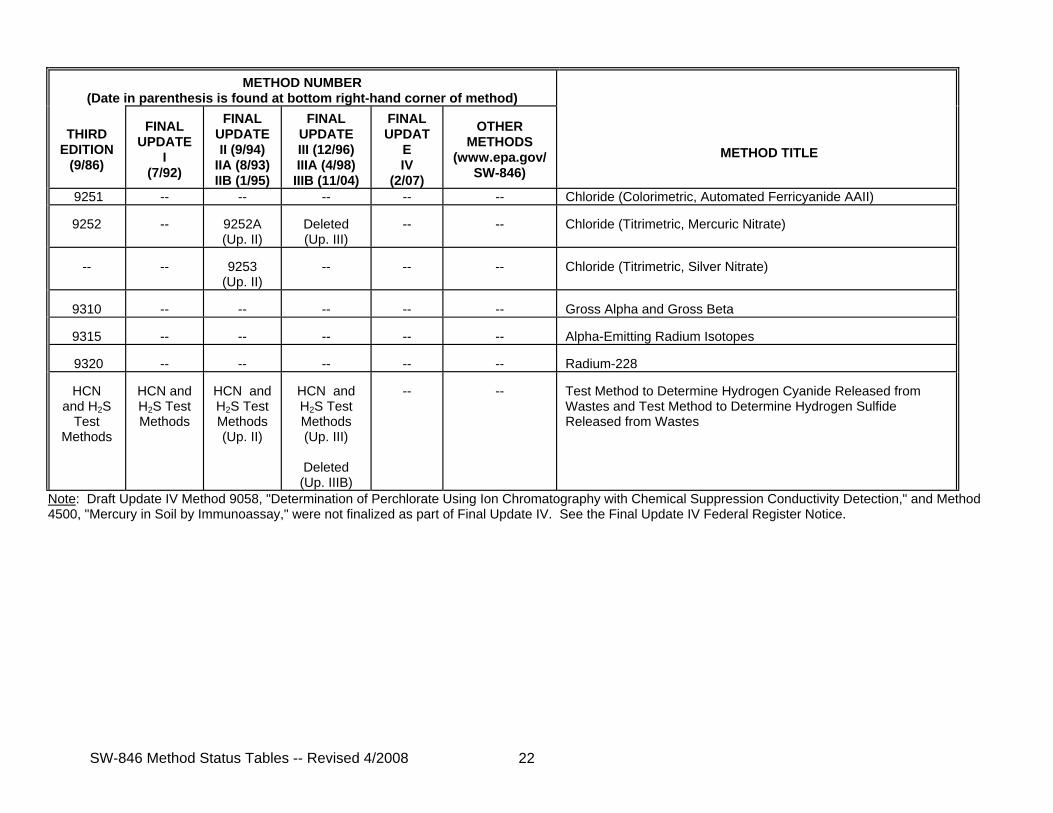
Note: Draft Update IV Method 9058, "Determination of Perchlorate Using Ion Chromatography with Chemical Suppression Conductivity Detection," and Method 4500, "Mercury in Soil by Immunoassay," were not finalized as part of Final Update IV. See the Final Update IV Federal Register Notice.
SW-846 Method Status Tables -- Revised 4/2008 23
STATUS TABLE FOR SW-846 CHAPTER TEXT AND OTHER DOCUMENTS
TITLE
THIRD ED.
(9/86)
FINAL UP. I (7/92)
FIN. UP. II (9/94) IIA (8/93) IIB (1/95)
FINAL UP. III (12/96) IIIA (4/98) IIIB (11/04)
FINAL UP. IV (2/07)
CURRENT FINAL
VERSION
Disclaimer
--
T
--
T (Up. III)
--
Rev 1 (12/96)
Abstract
T
T
T (Up. II)
--
--
Rev 2 (9/94)
Table of Contents
T
T
T (Up. II & IIB)
T (Up. III, IIIA, and IIIB)
T
Rev 7 (2/07)
Method Index and Conversion Table
T
--
--
--
--
Rev 0 (9/86)
Preface and Overview
T
--
--
T (Up. III)
--
Rev 1 (12/96)
Acknowledgments
T
--
--
--
--
Rev 0 (9/86)
Chapter One -- Quality Control
T
T
--
--
--
Rev 1 (7/92)
Chapter Two -- Choosing the Correct Procedure
T
T
T (Up. II)
T (Up. III)
T
Rev 4 (2/07)
Chapter Three -- Inorganic Analytes
T
T
T (Up. II)
T (Up. III)
T
Rev 4 (2/07)
Chapter Four -- Organic Analytes
T
--
T (Up. II)
T (Up. III)
T
Rev 4 (2/07)
Chapter Five -- Miscellaneous Test Methods
T
--
T (Up. II)
T (Up. III, IIIA and IIIB)
T
Rev 5 (2/07)
Chapter Six -- Properties
T
--
T T (Up. III and
T
Rev 5
SW-846 Method Status Tables -- Revised 4/2008 24
TITLE
THIRD ED.
(9/86)
FINAL UP. I (7/92)
FIN. UP. II (9/94) IIA (8/93) IIB (1/95)
FINAL UP. III (12/96) IIIA (4/98) IIIB (11/04)
FINAL UP. IV (2/07)
CURRENT FINAL
VERSION
(Up. II & IIB)
IIIB)
(2/07)
Chapter Seven -- Characteristics Introduction and Regulatory Definitions
T
T
T (Up. II)
T (Up. III and IIIB)
--
Rev 4 (11/04)
Chapter Eight --Methods for Determining Characteristics
T
--
T (Up. II)
T (Up. III and IIIB)
--
Rev 3 (11/04)
Chapter Nine -- Sampling Plan
T
--
--
--
--
Rev 0 (9/86)
Chapter Ten -- Sampling Methods
T
--
--
T (Up. III)
T
Rev 3 (2/07)
Chapter Eleven -- Ground Water Monitoring
T
--
--
--
T
Rev 1 (2/07)
Chapter Twelve -- Land Treatment Monitoring
T
--
--
--
--
Rev 0 (9/86)
Chapter Thirteen -- Incineration
T
--
--
--
--
Rev 0 (9/86)
Appendix -- Company References
T
--
--
--
--
Rev 0 (9/86)
CD-ROM ABSTRACT - 1 Revision 2 September 1994
ABSTRACT
Test Methods for Evaluating Solid Waste, Physical/Chemical Methods (SW-846)provides test procedures and guidance which are recommended for use in conductingthe evaluations and measurements needed to comply with the Resource Conservationand Recovery Act (RCRA), Public Law 94-580, as amended. These methods areapproved by the U.S. Environmental Protection Agency for obtaining data tosatisfy the requirements of 40 CFR Parts 122 through 270 promulgated under RCRA,as amended. This manual presents the state-of-the-art in routine analyticaltested adapted for the RCRA program. It contains procedures for field andlaboratory quality control, sampling, determining hazardous constituents inwastes, determining the hazardous characteristics of wastes (toxicity,ignitability, reactivity, and corrosivity), and for determining physicalproperties of wastes. It also contains guidance on how to select appropriatemethods.
Several of the hazardous waste regulations under Subtitle C of RCRA requirethat specific testing methods described in SW-846 be employed for certainapplications. Refer to 40 Code of Federal Regulations (CFR), Parts 260 through270, for those specific requirements. Any reliable analytical method may be usedto meet other requirements under Subtitle C of RCRA.
It is the goal of the U.S. Environmental Protection Agency's (EPA's)quality assurance (QA) program to ensure that all data be scientifically valid,defensible, and of known precision and accuracy. The data should be ofsufficient known quality to withstand scientific and legal challenge relative tothe use for which the data are obtained. The QA program is management's tool forachieving this goal.
For RCRA analyses, the recommended minimum requirements for a QA programand the associated quality control (QC) procedures are provided in this chapter.
The data acquired from QC procedures are used to estimate the quality ofanalytical data, to determine the need for corrective action in response toidentified deficiencies, and to interpret results after corrective actionprocedures are implemented. Method-specific QC procedures are incorporated inthe individual methods since they are not applied universally.
A total program to generate data of acceptable quality should include botha QA component, which encompasses the management procedures and controls, as wellas an operational day-to-day QC component. This chapter defines fundamentalelements of such a data collection program. Data collection efforts involve:
1. design of a project plan to achieve the data quality objectives(DQOs);
2. implementation of the project plan; and
3. assessment of the data to determine if the DQOs are met.
The project plan may be a sampling and analysis plan or a waste analysis plan ifit covers the QA/QC goals of the Chapter, or it may be a Quality AssuranceProject Plan as described later in this chapter.
This chapter identifies the minimal QC components that should be used inthe performance of sampling and analyses, including the QC information whichshould be documented. Guidance is provided to construct QA programs for fieldand laboratory work conducted in support of the RCRA program.
2.0 QA PROJECT PLAN
It is recommended that all projects which generate environment-related datain support of RCRA have a QA Project Plan (QAPjP) or equivalent. In someinstances, a sampling and analysis plan or a waste analysis plan may beequivalent if it covers all of the QA/QC goals outlined in this chapter. Inaddition, a separate QAPjP need not be prepared for routine analyses or
CD-ROM ONE - 2 Revision 1July 1992
activities where the procedures to be followed are described in a StandardOperating Procedures manual or similar document and include the elements of aQAPjP. These documents should be available and referenced in the documentationand/or records for the analysis activities. The term "QAPjP" in this chapterrefers to any of these QA/QC documents.
The QAPjP should detail the QA/QC goals and protocols for a specific datacollection activity. The QAPjP sets forth a plan for sampling and analysisactivities that will generate data of a quality commensurate with their intendeduse. QAPjP elements should include a description of the project and itsobjectives; a statement of the DQOs of the project; identification of those in-volved in the data collection and their responsibilities and authorities;reference to (or inclusion of) the specific sample collection and analysisprocedures that will be followed for all aspects of the project; enumeration ofQC procedures to be followed; and descriptions of all project documentation.Additional elements should be included in the QAPjP if needed to address allquality related aspects of the data collection project. Elements should beomitted only when they are inappropriate for the project or when absence of thoseelements will not affect the quality of data obtained for the project (seereference 1).
The role and importance of DQOs and project documentation are discussedbelow in Sections 2.1 through 2.6. Management and organization play a criticalrole in determining the effectiveness of a QA/QC program and ensuring that allrequired procedures are followed. Section 2.7 discusses the elements of anorganization's QA program that have been found to ensure an effective program.Field operations and laboratory operations (along with applicable QC procedures)are discussed in Sections 3 and 4, respectively.
2.1 DATA QUALITY OBJECTIVES
Data quality objectives (DQOs) for the data collection activity describethe overall level of uncertainty that a decision-maker is willing to accept inresults derived from environmental data. This uncertainty is used to specify thequality of the measurement data required, usually in terms of objectives forprecision, bias, representativeness, comparability and completeness. The DQOsshould be defined prior to the initiation of the field and laboratory work. Thefield and laboratory organizations performing the work should be aware of theDQOs so that their personnel may make informed decisions during the course of theproject to attain those DQOs. More detailed information on DQOs is availablefrom the U.S. EPA Quality Assurance Management Staff (QAMS) (see references 2 and4).
2.2 PROJECT OBJECTIVES
A statement of the project objectives and how the objectives are to beattained should be concisely stated and sufficiently detailed to permit clearunderstanding by all parties involved in the data collection effort. This
CD-ROM ONE - 3 Revision 1July 1992
includes a statement of what problem is to be solved and the information requiredin the process. It also includes appropriate statements of the DQOs (i.e., theacceptable level of uncertainty in the information).
2.3 SAMPLE COLLECTION
Sampling procedures, locations, equipment, and sample preservation andhandling requirements should be specified in the QAPjP. Further details onquality assurance procedures for field operations are described in Section 3 ofthis chapter. The OSW is developing policies and procedures for sampling in aplanned revision of Chapter Nine of this manual. Specific procedures forgroundwater sampling are provided in Chapter Eleven of this manual.
2.4 ANALYSIS AND TESTING
Analytes and properties of concern, analytical and testing procedures tobe employed, required detection limits, and requirements for precision and biasshould be specified. All applicable regulatory requirements and the project DQOsshould be considered when developing the specifications. Further details on theprocedures for analytical operations are described in Section 4 of this chapter.
2.5 QUALITY CONTROL
The quality assurance program should address both field and laboratoryactivities. Quality control procedures should be specified for estimating theprecision and bias of the data. Recommended minimum requirements for QC sampleshave been established by EPA and should be met in order to satisfy recommendedminimum criteria for acceptable data quality. Further details on procedures forfield and laboratory operations are described in Sections 3 and 4, respectively,of this chapter.
2.6 PROJECT DOCUMENTATION
Documents should be prepared and maintained in conjunction with the datacollection effort. Project documentation should be sufficient to allow reviewof all aspects of the work being performed. The QAPjP discussed in Sections 3and 4 is one important document that should be maintained.
The length of storage time for project records should comply withregulatory requirements, organizational policy, or project requirements,whichever is more stringent. It is recommended that documentation be stored forthree years from submission of the project final report.
Documentation should be secured in a facility that adequatelyaddresses/minimizes its deterioration for the length of time that it is to be
CD-ROM ONE - 4 Revision 1July 1992
retained. A system allowing for the expedient retrieval of information shouldexist.
Access to archived information should be controlled to maintain theintegrity of the data. Procedures should be developed to identify thoseindividuals with access to the data.
2.7 ORGANIZATION PERFORMING FIELD OR LABORATORY OPERATIONS
Proper design and structure of the organization facilitates effective andefficient transfer of information and helps to prevent important procedures frombeing overlooked.
The organizational structure, functional responsibilities, levels ofauthority, job descriptions, and lines of communication for all projectactivities should be established and documented. One person may cover more thanone organizational function. Each project participant should have a clearunderstanding of his or her duties and responsibilities and the relationship ofthose responsibilities to the overall data collection effort.
The management of each organization participating in a project involvingdata collection activities should establish that organization's operational andQA policies. This information should be documented in the QAPjP. The managementshould ensure that (1) the appropriate methodologies are followed as documentedin the QAPjPs; (2) personnel clearly understand their duties andresponsibilities; (3) each staff member has access to appropriate projectdocuments; (4) any deviations from the QAPjP are communicated to the projectmanagement and documented; and (5) communication occurs between the field,laboratory, and project management, as specified in the QAPjP. In addition, eachorganization should ensure that their activities do not increase the risk tohumans or the environment at or about the project location. Certain projects mayrequire specific policies or a Health and Safety Plan to provide this assurance.
The management of the participating field or laboratory organization shouldestablish personnel qualifications and training requirements for the project. Each person participating in the project should have the education, training,technical knowledge, and experience, or a combination thereof, to enable thatindividual to perform assigned functions. Training should be provided for eachstaff member as necessary to perform their functions properly. Personnelqualifications should be documented in terms of education, experience, andtraining, and periodically reviewed to ensure adequacy to currentresponsibilities.
Each participating field organization or laboratory organization shouldhave a designated QA function (i.e., a team or individual trained in QA) tomonitor operations to ensure that the equipment, personnel, activities,procedures, and documentation conform with the QAPjP. To the extent possible,the QA monitoring function should be entirely separate from, and independent of,
CD-ROM ONE - 5 Revision 1July 1992
personnel engaged in the work being monitored. The QA function should beresponsible for the QA review.
2.7.1 Performance Evaluation
Performance evaluation studies are used to measure the performance of thelaboratory on unknown samples. Performance evaluation samples are typicallysubmitted to the laboratory as blind samples by an independent outside source.The results are compared to predetermined acceptance limits. Performanceevaluation samples can also be submitted to the laboratory as part of the QAfunction during internal assessment of laboratory performance. Records of allperformance evaluation studies should be maintained by the laboratory. Problemsidentified through participation in performance evaluation studies should beimmediately investigated and corrected.
2.7.2 Internal Assessment by QA Function
Personnel performing field and laboratory activities are responsible forcontinually monitoring individual compliance with the QAPjP. The QA functionshould review procedures, results and calculations to determine compliance withthe QAPjP. The results of this internal assessment should be reported tomanagement with requirements for a plan to correct observed deficiencies.
2.7.3 External Assessment
The field and laboratory activities may be reviewed by personnel externalto the organization. Such an assessment is an extremely valuable method foridentifying overlooked problems. The results of the external assessment shouldbe submitted to management with requirements for a plan to correct observeddeficiencies.
2.7.4 On-Site Evaluation
On-site evaluations may be conducted as part of both internal and externalassessments. The focus of an on-site evaluation is to evaluate the degree ofconformance of project activities with the applicable QAPjP. On-site evaluationsmay include, but are not limited to, a complete review of facilities, staff,training, instrumentation, procedures, methods, sample collection, analyses, QApolicies and procedures related to the generation of environmental data. Recordsof each evaluation should include the date of the evaluation, location, the areasreviewed, the person performing the evaluation, findings and problems, andactions recommended and taken to resolve problems. Any problems identified thatare likely to affect data integrity should be brought immediately to theattention of management.
2.7.4.1 Field Activities
The review of field activities should be conducted by one or more personsknowledgeable in the activities being reviewed and include evaluating, at aminimum, the following subjects:
CD-ROM ONE - 6 Revision 1July 1992
Completeness of Field Reports -- This review determines whether allrequirements for field activities in the QAPjP have been fulfilled, thatcomplete records exist for each field activity, and that the proceduresspecified in the QAPjP have been implemented. Emphasis on fielddocumentation will help assure sample integrity and sufficient technicalinformation to recreate each field event. The results of thiscompleteness check should be documented, and environmental data affectedby incomplete records should be identified.
Identification of Valid Samples -- This review involves interpretation andevaluation of the field records to detect problems affecting the repre-sentativeness of environmental samples. Examples of items that mightindicate potentially invalid samples include improper well development,improperly screened wells, instability of pH or conductivity, and collec-tion of volatiles near internal combustion engines. The field recordsshould be evaluated against the QAPjP and SOPs. The reviewer should docu-ment the sample validity and identify the environmental data associatedwith any poor or incorrect field work.
Correlation of Field Test Data -- This review involves comparing anyavailable results of field measurements obtained by more than one method.For example, surface geophysical methods should correlate with directmethods of site geologic characterization such as lithologic logsconstructed during drilling operations.
Identification of Anomalous Field Test Data -- This review identifies anyanomalous field test data. For example, a water temperature for one wellthat is 5 degrees higher than any other well temperature in the sameaquifer should be noted. The reviewer should evaluate the impact ofanomalous field measurement results on the associated environmental data.
Validation of Field Analyses -- This review validates and documents alldata from field analysis that are generated in situ or from a mobilelaboratory as specified in Section 2.7.4.2. The reviewer should documentwhether the QC checks meet the acceptance criteria, and whether correctiveactions were taken for any analysis performed when acceptance criteriawere exceeded.
2.7.4.2 Laboratory Activities
The review of laboratory data should be conducted by one or more personsknowledgeable in laboratory activities and include evaluating, at a minimum, thefollowing subjects:
Completeness of Laboratory Records -- This review determines whether: (1)all samples and analyses required by the QAPjP have been processed, (2)complete records exist for each analysis and the associated QC samples,and that (3) the procedures specified in the QAPjP have been implemented.The results of the completeness check should be documented, andenvironmental data affected by incomplete records should be identified.
CD-ROM ONE - 7 Revision 1July 1992
Evaluation of Data with Respect to Detection and Quantitation Limits --This review compares analytical results to required quantitation limits.Reviewers should document instances where detection or quantitation limitsexceed regulatory limits, action levels, or target concentrationsspecified in the QAPjP.
Evaluation of Data with Respect to Control Limits -- This review comparesthe results of QC and calibration check samples to control criteria.Corrective action should be implemented for data not within controllimits. The reviewer should check that corrective action reports, and theresults of reanalysis, are available. The review should determinewhether samples associated with out-of-control QC data are identified ina written record of the data review, and whether an assessment of theutility of such analytical results is recorded.
Review of Holding Time Data -- This review compares sample holding timesto those required by the QAPjP, and notes all deviations.
Review of Performance Evaluation (PE) Results -- PE study results can behelpful in evaluating the impact of out-of-control conditions. This reviewdocuments any recurring trends or problems evident in PE studies andevaluates their effect on environmental data.
Correlation of Laboratory Data -- This review determines whether theresults of data obtained from related laboratory tests, e.g., PurgeableOrganic Halides (POX) and Volatile Organics, are documented, and whetherthe significance of any differences is discussed in the reports.
2.7.5 QA Reports
There should be periodic reporting of pertinent QA/QC information to theproject management to allow assessment of the overall effectiveness of the QAprogram. There are three major types of QA reports to project management:
Periodic Report on Key QA Activities -- Provides summary of key QA activi-ties during the period, stressing measures that are being taken to improvedata quality; describes significant quality problems observed andcorrective actions taken; reports information regarding any changes incertification/accreditation status; describes involvement in resolution ofquality issues with clients or agencies; reports any QA organizationalchanges; and provides notice of the distribution of revised documentscontrolled by the QA organization (i.e., procedures).
Report on Measurement Quality Indicators -- Includes the assessment of QCdata gathered over the period, the frequency of analyses repeated due tounacceptable QC performance, and, if possible, the reason for the unac-ceptable performance and corrective action taken.
Reports on QA Assessments -- Includes the results of the assessments andthe plan for correcting identified deficiencies; submitted immediately
CD-ROM ONE - 8 Revision 1July 1992
following any internal or external on-site evaluation or upon receipt ofthe results of any performance evaluation studies.
3.0 FIELD OPERATIONS
The field operations should be conducted in such a way as to providereliable information that meets the DQOs. To achieve this, certain minimalpolicies and procedures should be implemented. The OSW is considering revisionsof Chapter Nine and Eleven of this manual. Supplemental information and guidanceis available in the RCRA Ground-Water Monitoring Technical Enforcement GuidanceDocument (TEGD) (Reference 3). The project documentation should contain theinformation specified below.
3.1 FIELD LOGISTICS
The QAPjP should describe the type(s) of field operations to be performedand the appropriate area(s) in which to perform the work. The QAPjP shouldaddress ventilation, protection from extreme weather and temperatures, access tostable power, and provision for water and gases of required purity.
Whenever practical, the sampling site facilities should be examined priorto the start of work to ensure that all required items are available. The actualarea of sampling should be examined to ensure that trucks, drilling equipment,and personnel have adequate access to the site.
The determination as to whether sample shipping is necessary should be madeduring planning for the project. This need is established by evaluating theanalyses to be performed, sample holding times, and location of the site and thelaboratory. Shipping or transporting of samples to a laboratory should be donewithin a timeframe such that recommended holding times are met.
Samples should be packaged, labelled, preserved (e.g., preservative added,iced, etc.), and documented in an area which is free of contamination andprovides for secure storage. The level of custody and whether sample storage isneeded should be addressed in the QAPjP.
Storage areas for solvents, reagents, standards, and reference materialsshould be adequate to preserve their identity, concentration, purity, andstability prior to use.
Decontamination of sampling equipment may be performed at the locationwhere sampling occurs, prior to going to the sampling site, or in designatedareas near the sampling site. Project documentation should specify where and howthis work is accomplished. If decontamination is to be done at the site, waterand solvents of appropriate purity should be available. The method ofaccomplishing decontamination, including the required materials, solvents, andwater purity should be specified.
CD-ROM ONE - 9 Revision 1July 1992
During the sampling process and during on-site or in situ analyses, wastematerials are sometimes generated. The method for storage and disposal of thesewaste materials that complies with applicable local, state and Federalregulations should be specified. Adequate facilities should be provided for thecollection and storage of all wastes, and these facilities should be operated soas to minimize environmental contamination. Waste storage and disposalfacilities should comply with applicable federal, state, and local regulations.
The location of long-term and short-term storage for field records, and themeasures to ensure the integrity of the data should be specified.
3.2 EQUIPMENT/INSTRUMENTATION
The equipment, instrumentation, and supplies at the sampling site shouldbe specified and should be appropriate to accomplish the activities planned. Theequipment and instrumentation should meet the requirements of specifications,methods, and procedures as specified in the QAPjP.
3.3 OPERATING PROCEDURES
The QAPjP should describe or make reference to all field activities thatmay affect data quality. For routinely performed activities, standard operatingprocedures (SOPs) are often prepared to ensure consistency and to save time andeffort in preparing QAPjPs. Any deviation from an established procedure duringa data collection activity should be documented. The procedures should beavailable for the indicated activities, and should include, at a minimum, theinformation described below.
3.3.1 Sample Management
The numbering and labeling system, chain-of-custody procedures, and how thesamples are to be tracked from collection to shipment or receipt by thelaboratory should be specified. Sample management procedures should also specifythe holding times, volumes of sample required by the laboratory, requiredpreservatives, and shipping requirements.
3.3.2 Reagent/Standard Preparation
The procedures describing how to prepare standards and reagents should bespecified. Information concerning specific grades of materials used in reagentand standard preparation, appropriate glassware and containers for preparationand storage, and labeling and record keeping for stocks and dilutions should beincluded.
3.3.3 Decontamination
The procedures describing decontamination of field equipment before andduring the sample collection process should be specified. These procedures
CD-ROM ONE - 10 Revision 1July 1992
should include cleaning materials used, the order of washing and rinsing with thecleaning materials, requirements for protecting or covering cleaned equipment,and procedures for disposing of cleaning materials.
3.3.4 Sample Collection
The procedures describing how the sampling operations are actuallyperformed in the field should be specified. A simple reference to standardmethods is not sufficient, unless a procedure is performed exactly as describedin the published method. Methods from source documents published by the EPA,American Society for Testing and Materials, U.S. Department of the Interior,National Water Well Association, American Petroleum Institute, or otherrecognized organizations with appropriate expertise should be used, if possible.The procedures for sample collection should include at least the following:
@ Applicability of the procedure,
@ Equipment required,
@ Detailed description of procedures to be followed in collecting thesamples,
@ Common problems encountered and corrective actions to be followed, and
@ Precautions to be taken.
3.3.5 Field Measurements
The procedures describing all methods used in the field to determine achemical or physical parameter should be described in detail. The proceduresshould address criteria from Section 4, as appropriate.
3.3.6 Equipment Calibration And Maintenance
The procedures describing how to ensure that field equipment andinstrumentation are in working order should be specified. These describecalibration procedures and schedules, maintenance procedures and schedules,maintenance logs, and service arrangements for equipment. Calibration andmaintenance of field equipment and instrumentation should be in accordance withmanufacturers' specifications or applicable test specifications and should bedocumented.
3.3.7 Corrective Action
The procedures describing how to identify and correct deficiencies in thesample collection process should be specified. These should include specificsteps to take in correcting deficiencies such as performing additionaldecontamination of equipment, resampling, or additional training of fieldpersonnel. The procedures should specify that each corrective action should bedocumented with a description of the deficiency and the corrective action taken,
CD-ROM ONE - 11 Revision 1July 1992
and should include the person(s) responsible for implementing the correctiveaction.
3.3.8 Data Reduction and Validation
The procedures describing how to compute results from field measurementsand to review and validate these data should be specified. They should includeall formulas used to calculate results and procedures used to independentlyverify that field measurement results are correct.
3.3.9 Reporting
The procedures describing the process for reporting the results of fieldactivities should be specified.
3.3.10 Records Management
The procedures describing the means for generating, controlling, andarchiving project-specific records and field operations records should bespecified. These procedures should detail record generation and control and therequirements for record retention, including type, time, security, and retrievaland disposal authorities.
Project-specific records relate to field work performed for a project.These records may include correspondence, chain-of-custody records, fieldnotes, all reports issued as a result of the work, and procedures used.
Field operations records document overall field operations and may includeequipment performance and maintenance logs, personnel files, general fieldprocedures, and corrective action reports.
3.3.11 Waste Disposal
The procedures describing the methods for disposal of waste materialsresulting from field operations should be specified.
3.4 FIELD QA AND QC REQUIREMENTS
The QAPjP should describe how the following elements of the field QCprogram will be implemented.
3.4.1 Control Samples
Control samples are QC samples that are introduced into a process tomonitor the performance of the system. Control samples, which may include blanks(e.g., trip, equipment, and laboratory), duplicates, spikes, analyticalstandards, and reference materials, can be used in different phases of the datacollection process beginning with sampling and continuing through transportation,storage, and analysis.
CD-ROM ONE - 12 Revision 1July 1992
Each day of sampling, at least one field duplicate and one equipmentrinsate should be collected for each matrix sampled. If this frequency is notappropriate for the sampling equipment and method, then the appropriate changesshould be clearly identified in the QAPjP. When samples are collected forvolatile organic analysis, a trip blank is also recommended for each day thatsamples are collected. In addition, for each sampling batch (20 samples of onematrix type), enough volume should be collected for at least one sample so as toallow the laboratory to prepare one matrix spike and either one matrix duplicateor one matrix spike duplicate for each analytical method employed. This meansthat the following control samples are recommended:
@Field duplicate (one per day per matrix type)@Equipment rinsate (one per day per matrix type)@Trip blank (one per day, volatile organics only)@Matrix spike (one per batch [20 samples of each matrix type])@Matrix duplicate or matrix spike duplicate (one per batch)
Additional control samples may be necessary in order to assure data quality tomeet the project-specific DQOs.
3.4.2 Acceptance Criteria
Procedures should be in place for establishing acceptance criteria forfield activities described in the QAPjP. Acceptance criteria may be qualitativeor quantitative. Field events or data that fall outside of establishedacceptance criteria may indicate a problem with the sampling process that shouldbe investigated.
3.4.3 Deviations
All deviations from plan should be documented as to the extent of, andreason for, the deviation. Any activity not performed in accordance withprocedures or QAPjPs is considered a deviation from plan. Deviations from planmay or may not affect data quality.
3.4.4 Corrective Action
Errors, deficiencies, deviations, certain field events, or data that falloutside established acceptance criteria should be investigated. In some in-stances, corrective action may be needed to resolve the problem and restoreproper functioning to the system. The investigation of the problem and anysubsequent corrective action taken should be documented.
3.4.5 Data Handling
All field measurement data should be reduced according to protocolsdescribed or referenced in the QAPjP. Computer programs used for data reductionshould be validated before use and verified on a regular basis. All informationused in the calculations should be recorded to enable reconstruction of the finalresult at a later date.
CD-ROM ONE - 13 Revision 1July 1992
Data should be reported in accordance with the requirements of the end-useras described in the QAPjP.
3.5 QUALITY ASSURANCE REVIEW
The QA Review consists of internal and external assessments to ensure thatQA/QC procedures are in use and to ensure that field staff conform to theseprocedures. QA review should be conducted as deemed appropriate and necessary.
3.6 FIELD RECORDS
Records provide the direct evidence and support for the necessary technicalinterpretations, judgments, and discussions concerning project activities. Theserecords, particularly those that are anticipated to be used as evidentiary data,should directly support current or ongoing technical studies and activities andshould provide the historical evidence needed for later reviews and analyses.Records should be legible, identifiable, and retrievable and protected againstdamage, deterioration, or loss. The discussion in this section (3.6) outlinesrecommended procedures for record keeping. Organizations which conduct fieldsampling should develop appropriate record keeping procedures which satisfyrelevant technical and legal requirements.
Field records generally consist of bound field notebooks with prenumberedpages, sample collection forms, personnel qualification and training forms,sample location maps, equipment maintenance and calibration forms, chain-of-custody forms, sample analysis request forms, and field change request forms.All records should be written in indelible ink.
Procedures for reviewing, approving, and revising field records should beclearly defined, with the lines of authority included. It is recommended thatall documentation errors should be corrected by drawing a single line through theerror so it remains legible and should be initialed by the responsibleindividual, along with the date of change. The correction should be writtenadjacent to the error.
Records should include (but are not limited to) the following:
Calibration Records & Traceability of Standards/Reagents -- Calibration isa reproducible reference point to which all sample measurements can becorrelated. A sound calibration program should include provisions fordocumentation of frequency, conditions, standards, and records reflectingthe calibration history of a measurement system. The accuracy of thecalibration standards is important because all data will be in referenceto the standards used. A program for verifying and documenting theaccuracy of all working standards against primary grade standards shouldbe routinely followed.
CD-ROM ONE - 14 Revision 1July 1992
Sample Collection -- To ensure maximum utility of the sampling effort andresulting data, documentation of the sampling protocol, as performed inthe field, is essential. It is recommended that sample collection recordscontain, at a minimum, the names of persons conducting the activity,sample number, sample location, equipment used, climatic conditions,documentation of adherence to protocol, and unusual observations. Theactual sample collection record is usually one of the following: a boundfield notebook with prenumbered pages, a pre-printed form, or digitizedinformation on a computer tape or disc.
Chain-of-Custody Records -- The chain-of-custody involving the possessionof samples from the time they are obtained until they are disposed orshipped off-site should be documented as specified in the QAPjP and shouldinclude the following information: (1) the project name; (2) signaturesof samplers; (3) the sample number, date and time of collection, and grabor composite sample designation; (4) signatures of individuals involved insample transfer; and (5) if applicable, the air bill or other shippingnumber.
Maps and Drawings -- Project planning documents and reports often containmaps. The maps are used to document the location of sample collectionpoints and monitoring wells and as a means of presenting environmentaldata. Information used to prepare maps and drawings is normally obtainedthrough field surveys, property surveys, surveys of monitoring wells,aerial photography or photogrammetric mapping. The final, approved mapsand/or drawings should have a revision number and date and should be sub-ject to the same controls as other project records.
QC Samples -- Documentation for generation of QC samples, such as trip andequipment rinsate blanks, duplicate samples, and any field spikes shouldbe maintained.
Deviations -- All deviations from procedural documents and the QAPjPshould be recorded in the site logbook.
Reports -- A copy of any report issued and any supporting documentationshould be retained.
4.0 LABORATORY OPERATIONS
The laboratory should conduct its operations in such a way as to providereliable information. To achieve this, certain minimal policies and proceduresshould be implemented.
4.1 FACILITIES
The QAPjP should address all facility-related issues that may impactproject data quality. Each laboratory should be of suitable size and
CD-ROM ONE - 15 Revision 1July 1992
construction to facilitate the proper conduct of the analyses. Adequate benchspace or working area per analyst should be provided. The space requirement peranalyst depends on the equipment or apparatus that is being utilized, the numberof samples that the analyst is expected to handle at any one time, and the numberof operations that are to be performed concurrently by a single analyst. Otherissues to be considered include, but are not limited to, ventilation, lighting,control of dust and drafts, protection from extreme temperatures, and access toa source of stable power.
Laboratories should be designed so that there is adequate separation offunctions to ensure that no laboratory activity has an adverse effect on theanalyses. The laboratory may require specialized facilities such as a perchloricacid hood or glovebox.
Separate space for laboratory operations and appropriate ancillary supportshould be provided, as needed, for the performance of routine and specializedprocedures.
As necessary to ensure secure storage and prevent contamination ormisidentification, there should be adequate facilities for receipt and storageof samples. The level of custody required and any special requirements forstorage such as refrigeration should be described in planning documents.
Storage areas for reagents, solvents, standards, and reference materialsshould be adequate to preserve their identity, concentration, purity, andstability.
Adequate facilities should be provided for the collection and storage ofall wastes, and these facilities should be operated so as to minimize environ-mental contamination. Waste storage and disposal facilities should comply withapplicable federal, state, and local regulations.
The location of long-term and short-term storage of laboratory records andthe measures to ensure the integrity of the data should be specified.
4.2 EQUIPMENT/INSTRUMENTATION
Equipment and instrumentation should meet the requirements and specifica-tions of the specific test methods and other procedures as specified in theQAPjP. The laboratory should maintain an equipment/instrument description listthat includes the manufacturer, model number, year of purchase, accessories, andany modifications, updates, or upgrades that have been made.
4.3 OPERATING PROCEDURES
The QAPjP should describe or make reference to all laboratory activitiesthat may affect data quality. For routinely performed activities, SOPs are oftenprepared to ensure consistency and to save time and effort in preparing QAPjPs.
CD-ROM ONE - 16 Revision 1July 1992
Any deviation from an established procedure during a data collection activityshould be documented. It is recommended that procedures be available for theindicated activities, and include, at a minimum, the information describedbelow.
4.3.1 Sample Management
The procedures describing the receipt, handling, scheduling, and storageof samples should be specified.
Sample Receipt and Handling -- These procedures describe the precautionsto be used in opening sample shipment containers and how to verify thatchain-of-custody has been maintained, examine samples for damage, checkfor proper preservatives and temperature, and log samples into thelaboratory sample streams.
Sample Scheduling -- These procedures describe the sample scheduling inthe laboratory and includes procedures used to ensure that holding timerequirements are met.
Sample Storage -- These procedures describe the storage conditions for allsamples, verification and documentation of daily storage temperature, andhow to ensure that custody of the samples is maintained while in thelaboratory.
4.3.2 Reagent/Standard Preparation
The procedures describing how to prepare standards and reagents should bespecified. Information concerning specific grades of materials used in reagentand standard preparation, appropriate glassware and containers for preparationand storage, and labeling and recordkeeping for stocks and dilutions should beincluded.
4.3.3 General Laboratory Techniques
The procedures describing all essentials of laboratory operations that arenot addressed elsewhere should be specified. These techniques should include,but are not limited to, glassware cleaning procedures, operation of analyticalbalances, pipetting techniques, and use of volumetric glassware.
4.3.4 Test Methods
Procedures for test methods describing how the analyses are actuallyperformed in the laboratory should be specified. A simple reference to standardmethods is not sufficient, unless the analysis is performed exactly as describedin the published method. Whenever methods from SW-846 are not appropriate,recognized methods from source documents published by the EPA, American PublicHealth Association (APHA), American Society for Testing and Materials (ASTM), theNational Institute for Occupational Safety and Health (NIOSH), or otherrecognized organizations with appropriate expertise should be used, if possible.
CD-ROM ONE - 17 Revision 1July 1992
The documentation of the actual laboratory procedures for analytical methodsshould include the following:
Sample Preparation and Analysis Procedures -- These include applicableholding time, extraction, digestion, or preparation steps as appropriateto the method; procedures for determining the appropriate dilution toanalyze; and any other information required to perform the analysisaccurately and consistently.
Instrument Standardization -- This includes concentration(s) and frequencyof analysis of calibration standards, linear range of the method, andcalibration acceptance criteria.
Sample Data -- This includes recording requirements and documentation in-cluding sample identification number, analyst, data verification, date ofanalysis and verification, and computational method(s).
Precision and Bias -- This includes all analytes for which the method isapplicable and the conditions for use of this information.
Detection and Reporting Limits -- This includes all analytes in themethod.
Test-Specific QC -- This describes QC activities applicable to thespecific test and references any applicable QC procedures.
4.3.5 Equipment Calibration and Maintenance
The procedures describing how to ensure that laboratory equipment andinstrumentation are in working order should be specified. These proceduresinclude calibration procedures and schedules, maintenance procedures andschedules, maintenance logs, service arrangements for all equipment, and spareparts available in-house. Calibration and maintenance of laboratory equipmentand instrumentation should be in accordance with manufacturers' specificationsor applicable test specifications and should be documented.
4.3.6 QC
The type, purpose, and frequency of QC samples to be analyzed in thelaboratory and the acceptance criteria should be specified. Information shouldinclude the applicability of the QC sample to the analytical process, thestatistical treatment of the data, and the responsibility of laboratory staff andmanagement in generating and using the data. Further details on development ofproject-specific QC protocols are described in Section 4.4.
4.3.7 Corrective Action
The procedures describing how to identify and correct deficiencies in theanalytical process should be specified. These should include specific steps totake in correcting the deficiencies such as preparation of new standards and
CD-ROM ONE - 18 Revision 1July 1992
reagents, recalibration and restandardization of equipment, reanalysis ofsamples, or additional training of laboratory personnel in methods andprocedures. The procedures should specify that each corrective action should bedocumented with a description of the deficiency and the corrective action taken,and should include the person(s) responsible for implementing the correctiveaction.
4.3.8 Data Reduction and Validation
The procedures describing how to review and validate the data should bespecified. They should include procedures for computing and interpreting theresults from QC samples, and independent procedures to verify that the analyticalresults are reported correctly. In addition, routine procedures used to monitorprecision and bias, including evaluations of reagent, equipment rinsate, and tripblanks, calibration standards, control samples, duplicate and matrix spikesamples, and surrogate recovery, should be detailed in the procedures. Moredetailed validation procedures should be performed when required in the contractor QAPjP.
4.3.9 Reporting
The procedures describing the process for reporting the analytical resultsshould be specified.
4.3.10 Records Management
The procedures describing the means for generating, controlling, andarchiving laboratory records should be specified. The procedures should detailrecord generation and control, and the requirements for record retention, includ-ing type, time, security, and retrieval and disposal authorities.
Project-specific records may include correspondence, chain-of-custodyrecords, request for analysis, calibration data records, raw and finishedanalytical and QC data, data reports, and procedures used.
Laboratory operations records may include laboratory notebooks, instrumentperformance logs and maintenance logs in bound notebooks with prenumberedpages; laboratory benchsheets; software documentation; control charts;reference material certification; personnel files; laboratory procedures;and corrective action reports.
4.3.11 Waste Disposal
The procedures describing the methods for disposal of chemicals includingstandard and reagent solutions, process waste, and samples should be specified.
4.4 LABORATORY QA AND QC PROCEDURES
CD-ROM ONE - 19 Revision 1July 1992
The QAPjP should describe how the following required elements of thelaboratory QC program are to be implemented.
4.4.1 Method Proficiency
Procedures should be in place for demonstrating proficiency with eachanalytical method routinely used in the laboratory. These should includeprocedures for demonstrating the precision and bias of the method as performedby the laboratory and procedures for determining the method detection limit(MDL). All terminology, procedures and frequency of determinations associatedwith the laboratory's establishment of the MDL and the reporting limit should bewell-defined and well-documented. Documented precision, bias, and MDLinformation should be maintained for all methods performed in the laboratory.
4.4.2 Control Limits
Procedures should be in place for establishing and updating control limitsfor analysis. Control limits should be established to evaluate laboratoryprecision and bias based on the analysis of control samples. Typically, controllimits for bias are based on the historical mean recovery plus or minus threestandard deviation units, and control limits for precision range from zero (nodifference between duplicate control samples) to the historical mean relativepercent difference plus three standard deviation units. Procedures should be inplace for monitoring historical performance and should include graphical (controlcharts) and/or tabular presentations of the data.
4.4.3 Laboratory Control Procedures
Procedures should be in place for demonstrating that the laboratory is incontrol during each data collection activity. Analytical data generated withlaboratory control samples that fall within prescribed limits are judged to begenerated while the laboratory was in control. Data generated with laboratorycontrol samples that fall outside the established control limits are judged tobe generated during an "out-of-control" situation. These data are consideredsuspect and should be repeated or reported with qualifiers.
Laboratory Control Samples -- Laboratory control samples should beanalyzed for each analytical method when appropriate for the method. Alaboratory control sample consists of either a control matrix spiked withanalytes representative of the target analytes or a certified referencematerial.
Laboratory control sample(s) should be analyzed with each batch of samplesprocessed to verify that the precision and bias of the analytical processare within control limits. The results of the laboratory controlsample(s) are compared to control limits established for both precisionand bias to determine usability of the data.
Method Blank -- When appropriate for the method, a method blank should beanalyzed with each batch of samples processed to assess contamination
CD-ROM ONE - 20 Revision 1July 1992
levels in the laboratory. Guidelines should be in place for accepting orrejecting data based on the level of contamination in the blank.
Procedures should be in place for documenting the effect of the matrix onmethod performance. When appropriate for the method, there should be at leastone matrix spike and either one matrix duplicate or one matrix spike duplicateper analytical batch. Additional control samples may be necessary to assure dataquality to meet the project-specific DQOs.
Matrix-Specific Bias -- Procedures should be in place for determining thebias of the method due to the matrix. These procedures should includepreparation and analysis of matrix spikes, selection and use of surrogatesfor organic methods, and the method of standard additions for metal andinorganic methods. When the concentration of the analyte in the sample isgreater than 0.1%, no spike is necessary.
Matrix-Specific Precision -- Procedures should be in place for determiningthe precision of the method for a specific matrix. These proceduresshould include analysis of matrix duplicates and/or matrix spikeduplicates. The frequency of use of these techniques should be based onthe DQO for the data collection activity.
Matrix-Specific Detection Limit -- Procedures should be in place fordetermining the MDL for a specific matrix type (e.g., wastewater treatmentsludge, contaminated soil, etc).
4.4.4 Deviations
Any activity not performed in accordance with laboratory procedures orQAPjPs is considered a deviation from plan. All deviations from plan should bedocumented as to the extent of, and reason for, the deviation.
4.4.5 Corrective Action
Errors, deficiencies, deviations, or laboratory events or data that falloutside of established acceptance criteria should be investigated. In someinstances, corrective action may be needed to resolve the problem and restoreproper functioning to the analytical system. The investigation of the problemand any subsequent corrective action taken should be documented.
4.4.6 Data Handling
Data resulting from the analyses of samples should be reduced according toprotocols described in the laboratory procedures. Computer programs used fordata reduction should be validated before use and verified on a regular basis.All information used in the calculations (e.g., raw data, calibration files,tuning records, results of standard additions, interference check results, andblank- or background-correction protocols) should be recorded in order to enablereconstruction of the final result at a later date. Information on thepreparation of the sample (e.g., weight or volume of sample used, percent dry
CD-ROM ONE - 21 Revision 1July 1992
weight for solids, extract volume, dilution factor used) should also bemaintained in order to enable reconstruction of the final result at a later date.
All data should be reviewed by a second analyst or supervisor according tolaboratory procedures to ensure that calculations are correct and to detecttranscription errors. Spot checks should be performed on computer calculationsto verify program validity. Errors detected in the review process should bereferred to the analyst(s) for corrective action. Data should be reported inaccordance with the requirements of the end-user. It is recommended that thesupporting documentation include at a minimum:
@ Laboratory name and address.
@ Sample information (including unique sample identification, samplecollection date and time, date of sample receipt, and date(s) of samplepreparation and analysis).
@ Analytical results reported with an appropriate number of significantfigures.
@ Detection limits that reflect dilutions, interferences, or correction forequivalent dry weight.
@ Method reference.
@ Appropriate QC results (correlation with sample batch should be traceableand documented).
@ Data qualifiers with appropriate references and narrative on the qualityof the results.
4.5 QUALITY ASSURANCE REVIEW
The QA review consists of internal and external assessments to ensure thatQA/QC procedures are in use and to ensure that laboratory staff conform to theseprocedures. QA review should be conducted as deemed appropriate and necessary.
4.6 LABORATORY RECORDS
Records provide the direct evidence and support for the necessary technicalinterpretations, judgements, and discussions concerning project activities.These records, particularly those that are anticipated to be used as evidentiarydata, should directly support technical studies and activities, and provide thehistorical evidence needed for later reviews and analyses. Records should belegible, identifiable, and retrievable, and protected against damage,deterioration, or loss. The discussion in this section (4.6) outlinesrecommended procedures for record keeping. Organizations which conduct field
CD-ROM ONE - 22 Revision 1July 1992
sampling should develop appropriate record keeping procedures which satisfyrelevant technical and legal requirements.
Laboratory records generally consist of bound notebooks with prenumberedpages, personnel qualification and training forms, equipment maintenance andcalibration forms, chain-of-custody forms, sample analysis request forms, andanalytical change request forms. All records should be written in indelible ink.
Procedures for reviewing, approving, and revising laboratory records shouldbe clearly defined, with the lines of authority included. Any documentationerrors should be corrected by drawing a single line through the error so that itremains legible and should be initialed by the responsible individual, along withthe date of change. The correction is written adjacent to the error.
Strip-chart recorder printouts should be signed by the person who performedthe instrumental analysis. If corrections need to be made in computerized data,a system parallel to the corrections for handwritten data should be in place.
Records of sample management should be available to permit the re-creationof an analytical event for review in the case of an audit or investigation of adubious result.
Laboratory records should include, at least, the following:
Operating Procedures -- Procedures should be available to those performingthe task outlined. Any revisions to laboratory procedures should bewritten, dated, and distributed to all affected individuals to ensureimplementation of changes. Areas covered by operating procedures aregiven in Sections 3.3 and 4.3.
Quality Assurance Plans -- The QAPjP should be on file.
Equipment Maintenance Documentation -- A history of the maintenance recordof each system serves as an indication of the adequacy of maintenanceschedules and parts inventory. As appropriate, the maintenance guidelinesof the equipment manufacturer should be followed. When maintenance isnecessary, it should be documented in either standard forms or inlogbooks. Maintenance procedures should be clearly defined and writtenfor each measurement system and required support equipment.
Proficiency -- Proficiency information on all compounds reported should bemaintained and should include (1) precision; (2) bias; (3) method detec-tion limits; (4) spike recovery, where applicable; (5) surrogate recovery,where applicable; (6) checks on reagent purity, where applicable; and(7) checks on glassware cleanliness, where applicable.
Calibration Records & Traceability of Standards/Reagents -- Calibration isa reproducible reference point to which all sample measurements can becorrelated. A sound calibration program should include provisions fordocumenting frequency, conditions, standards, and records reflecting the
CD-ROM ONE - 23 Revision 1July 1992
calibration history of a measurement system. The accuracy of thecalibration standards is important because all data will be in referenceto the standards used. A program for verifying and documenting theaccuracy and traceability of all working standards against appropriateprimary grade standards or the highest quality standards available shouldbe routinely followed.
Sample Management -- All required records pertaining to sample managementshould be maintained and updated regularly. These include chain-of-custody forms, sample receipt forms, and sample disposition records.
Original Data -- The raw data and calculated results for all samplesshould be maintained in laboratory notebooks, logs, benchsheets, files orother sample tracking or data entry forms. Instrumental output should bestored in a computer file or a hardcopy report.
QC Data -- The raw data and calculated results for all QC and fieldsamples and standards should be maintained in the manner described in thepreceding paragraph. Documentation should allow correlation of sampleresults with associated QC data. Documentation should also include thesource and lot numbers of standards for traceability. QC samples include,but are not limited to, control samples, method blanks, matrix spikes, andmatrix spike duplicates.
Correspondence -- Project correspondence can provide evidence supportingtechnical interpretations. Correspondence pertinent to the project shouldbe kept and placed in the project files.
Deviations -- All deviations from procedural and planning documents shouldbe recorded in laboratory notebooks. Deviations from QAPjPs should bereviewed and approved by the authorized personnel who performed theoriginal technical review or by their designees.
Final Report -- A copy of any report issued and any supporting documenta-tion should be retained.
5.0 DEFINITIONS
The following terms are defined for use in this document:
ACCURACY The closeness of agreement between an observed value andan accepted reference value. When applied to a set ofobserved values, accuracy will be a combination of arandom component and of a common systematic error (orbias) component.
BATCH: A group of samples which behave similarly with respect tothe sampling or the testing procedures being employed andwhich are processed as a unit (see Section 3.4.1 for field
CD-ROM ONE - 24 Revision 1July 1992
samples and Section 4.4.3 for laboratory samples). For QCpurposes, if the number of samples in a group is greaterthan 20, then each group of 20 samples or less will all behandled as a separate batch.
BIAS: The deviation due to matrix effects of the measured value(x - x ) from a known spiked amount. Bias can be assesseds u
by comparing a measured value to an accepted referencevalue in a sample of known concentration or by determiningthe recovery of a known amount of contaminant spiked intoa sample (matrix spike). Thus, the bias (B) due to matrixeffects based on a matrix spike is calculated as:
B = (x - x ) - Ks u
where:
x = measured value for spiked sample,s
x = measured value for unspiked sample, andu
K = known value of the spike in the sample.
Using the following equation yields the percent recovery(%R).
%R = 100 (x - x )/ Ks u
BLANK: see Equipment Rinsate, Method Blank, Trip Blank.
CONTROL SAMPLE: A QC sample introduced into a process to monitor theperformance of the system.
DATA QUALITY A statement of the overall level of uncertainty that aOBJECTIVES (DQOs): decision-maker is willing to accept in results derived
DATA VALIDATION: The process of evaluating the available data against the
from environmental data (see reference 2, EPA/QAMS, July16, 1986). This is qualitatively distinct from qualitymeasurements such as precision, bias, and detection limit.
project DQOs to make sure that the objectives are met.Data validation may be very rigorous, or cursory,depending on project DQOs. The available data reviewedwill include analytical results, field QC data and lab QCdata, and may also include field records.
DUPLICATE: see Matrix Duplicate, Field Duplicate, Matrix SpikeDuplicate.
EQUIPMENT BLANK: see Equipment Rinsate.
EQUIPMENT RINSATE: A sample of analyte-free media which has been used to
CD-ROM ONE - 25 Revision 1July 1992
rinse the sampling equipment. It is collected aftercompletion of decontamination and prior to sampling. Thisblank is useful in documenting adequate decontamination ofsampling equipment.
ESTIMATED The lowest concentration that can be reliably achievedQUANTITATION within specified limits of precision and accuracy duringLIMIT (EQL): routine laboratory operating conditions. The EQL is
generally 5 to 10 times the MDL. However, it may benominally chosen within these guidelines to simplify datareporting. For many analytes the EQL analyteconcentration is selected as the lowest non-zero standardin the calibration curve. Sample EQLs are highly matrix-dependent. The EQLs in SW-846 are provided for guidanceand may not always be achievable.
FIELD DUPLICATES: Independent samples which are collected as close aspossible to the same point in space and time. They aretwo separate samples taken from the same source, stored inseparate containers, and analyzed independently. Theseduplicates are useful in documenting the precision of thesampling process.
LABORATORY CONTROL A known matrix spiked with compound(s) representative ofSAMPLE: the target analytes. This is used to document laboratory
performance.
MATRIX: The component or substrate (e.g., surface water, drinkingwater) which contains the analyte of interest.
MATRIX DUPLICATE: An intralaboratory split sample which is used to documentthe precision of a method in a given sample matrix.
MATRIX SPIKE: An aliquot of sample spiked with a known concentration oftarget analyte(s). The spiking occurs prior to samplepreparation and analysis. A matrix spike is used todocument the bias of a method in a given sample matrix.
MATRIX SPIKE Intralaboratory split samples spiked with identicalDUPLICATES: concentrations of target analyte(s). The spiking occurs
prior to sample preparation and analysis. They are usedto document the precision and bias of a method in a givensample matrix.
METHOD BLANK: An analyte-free matrix to which all reagents are added inthe same volumes or proportions as used in sampleprocessing. The method blank should be carried throughthe complete sample preparation and analytical procedure.The method blank is used to document contaminationresulting from the analytical process.
CD-ROM ONE - 26 Revision 1July 1992
For a method blank to be acceptable for use with theaccompanying samples, the concentration in the blank ofany analyte of concern should not be higher than thehighest of either:
(1)The method detection limit, or
(2)Five percent of the regulatory limit for that analyte,or
(3)Five percent of the measured concentration in thesample.
METHOD DETECTION The minimum concentration of a substance that can beLIMIT (MDL): measured and reported with 99% confidence that the analyte
concentration is greater than zero and is determined fromanalysis of a sample in a given matrix type containingthe analyte.
For operational purposes, when it is necessary todetermine the MDL in the matrix, the MDL should bedetermined by multiplying the appropriate one-sided 99% t-statistic by the standard deviation obtained from aminimum of three analyses of a matrix spike containing theanalyte of interest at a concentration three to five timesthe estimated MDL, where the t-statistic is obtained fromstandard references or the table below.
Estimate the MDL as follows:Obtain the concentration value that corresponds to:
a) an instrument signal/noise ratio within the range of2.5 to 5.0, or
b) the region of the standard curve where there is asignificant change in sensitivity (i.e., a break in theslope of the standard curve).
s 2' 1n&1 j
n
i'1(xi&x)
2
x' 1nj
n
i'1xi
CD-ROM ONE - 27 Revision 1July 1992
Determine the variance (S ) for each analyte as follows:2
where x = the ith measurement of the variable x i
and x = the average value of x;_
Determine the standard deviation (s) for each analyte asfollows:
s = (S )2 1/2
Determine the MDL for each analyte as follows:
MDL = t (s)(n-1, = .99)
where t is the one-sided t-statistic appropriate(n-1, = .99)for the number of samples used to determine (s), at the 99percent level.
ORGANIC-FREE For volatiles, all references to water in the methodsREAGENT WATER: refer to water in which an interferant is not observed at
the method detection limit of the compounds of interest.Organic-free reagent water can be generated by passing tapwater through a carbon filter bed containing about 1 poundof activated carbon. A water purification system may beused to generate organic-free deionized water.Organic-free reagent water may also be prepared by boilingwater for 15 minutes and, subsequently, while maintainingthe temperature at 90EC, bubbling a contaminant-free inertgas through the water for 1 hour.
For semivolatiles and nonvolatiles, all references towater in the methods refer to water in which aninterferant is not observed at the method detection limitof the compounds of interest. Organic-free reagent watercan be generated by passing tap water through a carbonfilter bed containing about 1 pound of activated carbon.A water purification system may be used to generateorganic-free deionized water.
PRECISION: The agreement among a set of replicate measurements
CD-ROM ONE - 28 Revision 1July 1992
without assumption of knowledge of the true value.Precision is estimated by means of duplicate/replicateanalyses. These samples should contain concentrations ofanalyte above the MDL, and may involve the use of matrixspikes. The most commonly used estimates of precision arethe relative standard deviation (RSD) or the coefficientof variation (CV),
RSD = CV = 100 S/x,_
where: x = the arithmetic mean of the x measurements, and S =_
i
variance; and the relative percent difference (RPD) whenonly two samples are available.
RPD = 100 [(x - x )/{(x + x )/2}]. 1 2 1 2
PROJECT: Single or multiple data collection activities that arerelated through the same planning sequence.
QUALITY ASSURANCE An orderly assemblage of detailed procedures designed toPROJECT PLAN produce data of sufficient quality to meet the data(QAPjP): quality objectives for a specific data collection
activity.
RCRA: The Resource Conservation and Recovery Act.
REAGENT BLANK: See Method Blank.
REAGENT GRADE: Analytical reagent (AR) grade, ACS reagent grade, andreagent grade are synonymous terms for reagents whichconform to the current specifications of the Committee onAnalytical Reagents of the American Chemical Society.
REAGENT WATER: Water that has been generated by any method which wouldachieve the performance specifications for ASTM Type IIwater. For organic analyses, see the definition oforganic-free reagent water.
REFERENCE MATERIAL: A material containing known quantities of target analytesin solution or in a homogeneous matrix. It is used todocument the bias of the analytical process.
SPLIT SAMPLES: Aliquots of sample taken from the same container andanalyzed independently. In cases where aliquots ofsamples are impossible to obtain, field duplicate samplesshould be taken for the matrix duplicate analysis. Theseare usually taken after mixing or compositing and are usedto document intra- or interlaboratory precision.
CD-ROM ONE - 29 Revision 1July 1992
STANDARD ADDITION: The practice of adding a known amount of an analyte to asample immediately prior to analysis. It is typicallyused to evaluate interferences.
STANDARD CURVE: A plot of concentrations of known analyte standards versusthe instrument response to the analyte. Calibrationstandards are prepared by successively diluting a standardsolution to produce working standards which cover theworking range of the instrument. Standards should beprepared at the frequency specified in the appropriatesection. The calibration standards should be preparedusing the same type of acid or solvent and at the sameconcentration as will result in the samples followingsample preparation. This is applicable to organic andinorganic chemical analyses.
SURROGATE: An organic compound which is similar to the targetanalyte(s) in chemical composition and behavior in theanalytical process, but which is not normally found inenvironmental samples.
TRIP BLANK: A sample of analyte-free media taken from the laboratoryto the sampling site and returned to the laboratoryunopened. A trip blank is used to document contaminationattributable to shipping and field handling procedures.This type of blank is useful in documenting contaminationof volatile organics samples.
6.0 REFERENCES
1. Interim Guidelines and Specifications for Preparing Quality AssuranceProject Plans, QAMS-005/80, December 29, 1980, Office of Monitoring Systemsand Quality Assurance, ORD, U.S. EPA, Washington, DC 20460.
2. Development of Data Quality Objectives, Description of Stages I and II, July16, 1986, Quality Assurance Management Staff, ORD, U.S. EPA, Washington, DC20460.
3. RCRA Ground-Water Monitoring Technical Enforcement Guidance Document,September, 1986, Office of Waste Programs Enforcement. OSWER, U.S. EPA,Washington, DC, 20460.
4. DQO Training Software, Version 6.5, December, 1988, Quality AssuranceManagement Staff, ORD, U.S. EPA, Washington, DC 20460.
Prior to employing the methods in this chapter, analysts are advised to consult thedisclaimer statement at the front of this manual and the information in Chapter Two forguidance on the allowed flexibility in the choice of apparatus, reagents, and supplies. Inaddition, unless specified in a regulation, the use of SW-846 methods is not mandatory inresponse to Federal testing requirements. The information contained in each procedure isprovided by EPA as guidance to be used by the analyst and the regulated community in makingjudgements necessary to meet the data quality objectives or needs for the intended use of thedata.
The following methods are found in Chapter Ten:
Method 0010: Modified Method 5 Sampling TrainAppendix A: Preparation of XAD-2 Sorbent ResinAppendix B: Total Chromatographable Organic Material
AnalysisMethod 0011: Sampling for Selected Aldehyde and Ketone Emissions from
Stationary SourcesMethod 0020: Source Assessment Sampling System (SASS)Method 0023A: Sampling Method for Polychlorinated Dibenzo-p-Dioxins and
Polychlorinated Dibenzofuran Emissions from StationarySources
Method 0030: Volatile Organic Sampling TrainMethod 0031: Sampling Method for Volatile Organic Compounds (SMVOC)Method 0040: Sampling of Principal Organic Hazardous Constituents from
Combustion Sources Using Tedlar® BagsMethod 0050: Isokinetic HCl/Cl2 Emission Sampling TrainMethod 0051: Midget Impinger HCl/Cl2 Emission Sampling TrainMethod 0060: Determination of Metals in Stack EmissionsMethod 0061: Determination of Hexavalent Chromium Emissions from
Stationary SourcesMethod 0100: Sampling for Formaldehyde and Other Carbonyl Compounds
in Indoor AirMethod 25D: Determination of the Volatile Organic Concentration of Waste
SamplesMethod 25E: Determination of Vapor Phase Organic Concentration in Waste
SamplesMethod 207: A Method for Measuring Isocyanates in Stationary Source
Emissions
CD-ROM PREFACE ) 1 Revision 1December 1996
PREFACE AND OVERVIEW
PURPOSE OF THE MANUAL
Test Methods for Evaluating Solid Waste (SW-846) provides a unified, up-to-date source ofinformation on sampling and analysis related to compliance with RCRA regulations. It brings together intoone reference all sampling and testing methodologies approved by the Office of Solid Waste for use inimplementing the RCRA regulatory program. The manual provides methodologies for collecting and testingrepresentative samples of waste and other materials to be monitored. Aspects of sampling and testing inSW-846 include quality control, sampling plan development and implementation, analysis of inorganic andorganic constituents, the estimation of intrinsic physical properties, and the appraisal of wastecharacteristics.
The procedures described in this manual are meant to be comprehensive and detailed, coupled withthe realization that the problems encountered in sampling and analytical situations require a certain amountof flexibility. The solutions to these problems will depend, in part, on the skill, training, and experience ofthe analyst. For some situations, it is possible to use this manual in rote fashion. In other situations, it willrequire a combination of technical abilities, using the manual as guidance rather than in a step-by-step,word-by-word fashion. Although this puts an extra burden on the user, it is unavoidable because of thevariety of sampling and analytical conditions found with hazardous wastes.
ORGANIZATION AND FORMAT
This manual is divided into two volumes and thirteen chapters. Volume I focuses on laboratoryactivities and is divided into three sections: IA, IB, and IC. Volume IA deals with quality control procedures,selection of appropriate test methods, and analytical methods for inorganic species. Volume IB consists ofmethods for organic analytes. Volume IC includes a variety of test methods for miscellaneous analytes andproperties, including for use in evaluating whether a waste exhibits certain hazardous waste characteristics.Volume II deals with sample acquisition and includes quality control, sampling plan design andimplementation, and field sampling methods. Discussions regarding ground water monitoring, landtreatment monitoring, and incineration are also included in Volume II.
Volume I begins with an overview of the quality control procedures that should be adhered to duringapplication of the sampling and analysis methods. The quality control chapter (Chapter One) and themethod chapters are interdependent. The analytical procedures cannot be used without a thoroughunderstanding of the quality control requirements and the means to implement them. This understandingcan be achieved only by reviewing Chapter One and the analytical methods together. It is expected thatindividual laboratories, using SW-846 as the reference source, will select appropriate methods and developa standard operating procedure (SOP) to be followed by the laboratory. The SOP should incorporate thepertinent information from this manual adopted to the specific needs and circumstances of the individuallaboratory as well as to the materials to be evaluated.
The method selection chapter (Chapter Two) presents a comprehensive discussion of the applicationof these methods to various matrices in the determination of groups of analytes or specific analytes. It aidsthe chemist in constructing the correct analytical method from the array of procedures which may cover thematrix/analyte/concentration combination of interests. The section discusses the objective of the testingprogram and its relationship to the choice of an analytical method. Flow charts and tables provide guidancein the selection of the correct analytical procedures to form the appropriate method.
The analytical methods are separated into distinct procedures describing specific, independentanalytical operations. These include extraction, digestion, cleanup, and determination. This format allowslinking of the various steps in the analysis according to the type of sample (e.g., water, soil, sludge, still
CD-ROM PREFACE ) 2 Revision 1December 1996
bottom); analytes(s) of interest, needed sensitivity, and available analytical instrumentation. However,Chapters Five (Miscellaneous) and Six (Properties) give complete methods which are not amenable to suchsegmentation to form discrete procedures. The introductory material at the beginning of Chapters Three(Inorganic Analytes) and Four (Organic Analytes) contains information on sample handling and preservation,safety, and sample preparation.
Part II, Characteristics, of Volume I describes the hazardous waste characteristics (Chapter Seven)and methods used to determine if the waste is hazardous because it exhibits a particular characteristic(Chapters Seven and Eight).
Volume II gives background information on statistical and nonstatistical aspects of sampling. It alsopresents practical sampling techniques appropriate for situations presenting a variety of physical conditions.
Information regarding the regulatory aspects of several monitoring categories is also found in VolumeII. These categories include ground water monitoring (Chapter Eleven), land treatment (Chapter Twelve),and incineration (Chapter Thirteen). The purpose of this guidance is to orient the user to the analyticalobjective, and to assist in the development of data quality objectives, sampling plans, and SOPs.
Significant interferences, or other problems, may be encountered with certain samples. In thesesituations, the analyst is advised to contact the Methods Team (5307W), USEPA/OSW/EMRAD , 401 M St.1
SW, Washington, DC 20460 (703-308-8855) for assistance. The manual is intended to serve all those witha need to evaluate solid waste. Your comments, corrections, suggestions, and questions concerning anymaterial contained in, or omitted from, this manual will be gratefully appreciated. Please direct yourcomments to the above address.
SW-846 METHOD NUMBERS
When published as a new method to SW-846, a method's number does not include a letter suffix.However, each time the method is revised and promulgated as part of an SW-846 update, it receives a newletter suffix, i.e, a suffix of "A" indicates revision one of that method, a suffix of "B" indicates revision two,etc. In order to properly document the SW-846 method used during analysis, the entire method numberincluding the suffix letter designation must be identified by the analyst. In addition, a method reference foundwithin the RCRA regulations and the text of SW-846 methods and chapters always refers to the latestpromulgated revision of the method, even if the method number at those locations does not include theappropriate letter suffix.
United States Environmental Protection Agency; Office of Solid Waste; Economic, Methods, and1
Risk Analysis Division
ELEVEN - 1 Revision 1February 2007
CHAPTER ELEVEN
GROUND WATER MONITORING
For guidance regarding RCRA-related ground-water monitoring, see the EPA Office ofSolid Waste guidance document entitled "RCRA Ground-water Monitoring: Draft TechnicalGuidance," published in 1992. This document was distributed to update technical informationregarding ground-water monitoring contained in other sources of USEPA guidance, includingChapter Eleven of this manual.
A PDF of the guidance document can be viewed and obtained via the following EPA website link: http://www.epa.gov/epaoswer/hazwaste/test/info.htm
A PDF of the guidance document may also be viewed and obtained via the following EPAweb site link, select "Site Characterization/Monitoring: http://www.epa.gov/epaoswer/hazwaste/ca/guidance.htm
A monitoring program is an essential component at any land treatmentunit and should be planned to provide assurance of appropriate facilitydesign, to act as a feedback loop to furnish guidance on improving unitmanagement, and to indicate the rate at which the treatment capacity is beingapproached. Because many assumptions must be made in the design of a landtreatment unit, monitoring can be used to verify whether the initial data andassumptions were correct or if design or operational changes are needed.Monitoring cannot be substituted for careful design based on the fullestreasonable understanding of the effects of applying hazardous waste to thesoil; however, for existing Hazardous Waste Land Treatment (HWLT) units(which must retrofit to comply with regulations), monitoring can provide muchof the data base needed for demonstrating treatment. Figure 12-1 shows the topics to be considered when developing amonitoring program. The program must be developed to provide the followingassurances:
1. that the waste being applied does not deviate significantly fromthe waste for which the unit was designed;
2. that waste constituents are not leaching from the land treatmentarea in unacceptable concentrations;
3. that ground water is not being adversely affected by themigration of hazardous constituents of the waste(s); and
4. that waste constituents will not create a food-chain hazard ifcrops are harvested.
12.2 TREATMENT ZONE As is depicted in Figure 12-2, the entire land treatment operation andmonitoring program revolve about a central component, the treatment zone.Concentrating on the treatment zone is a useful approach to describing andmonitoring a land treatment system. The treatment zone is the soil to whichwastes are applied or incorporated; HWLT units are designed so thatdegradation, transformation, and immobilization of hazardous constituents andtheir metabolites occur within this zone.
In practice, setting a boundary to the treatment zone is difficult.In choosing the boundaries of the treatment zone, soil-forming processes andthe associated decrease in biological activity with depth should beconsidered.
TWELVE 2CD-ROM Revision 0 Date September 1986
Figure 12-1. Topics to be considered in developing a monitoring program for an HWLT unit.
TREATMENT ZONECONCEPT
WASTE
DESIGN AND OPERATION
ANALYTICALCONSIDERATIONS
STATISTICALCONSIDERATIONS
TYPES OFMONITORING
FINAL SITESELECTION
MONITORING
CONTINGENCY PLANNINGAND ADDITIONAL CONSIDERATIONS
TWELVE 3
CD-ROM Revision 0
Date September 1986
DISCHARGE/RUNOFF(NPDES)
~f1y!j
GROUNDWATER
WASTE
FOOD CHAIN CROPS
UNSATURATED ZONE
_'\1-
AIR
SOIL CORES
-~~ ..- --~
SOIL-PORELIQUID
\\- \ \--\ \\\ \\--\ \Figure 12-2. Various types of monitoring for land treatment units.
TWELVE 4CD-ROM Revision 0 Date September 1986
12.3 REGULATORY DEFINITION
The current regulations (U.S. EPA, 1982a) require the following typesof monitoring:
1. Ground water detection monitoring to determine if a leachateplume has reached the edge of the waste management area (40 CFR264.98).
2. Ground water compliance monitoring to determine if the facilityis complying with ground water protection standards forhazardous constituents (40 CFR 264.99).
3. Monitoring of soil pH and concentration of cadmium in the wastewhen certain food-chain crops are grown on HWLT units wherecadmium is disposed of (40 CFR 264.276).
4. Unsaturated zone monitoring, including soil cores and soil-poreliquid monitoring, to determine if hazardous constituents aremigrating out of the treatment zone (40 CFR 246.278).
5. Waste analysis of all types of waste to be disposed at the HWLTunit (40 CFR 264.13).
12.4 MONITORING AND SAMPLING STRATEGY
As discussed earlier, the monitoring program centers around thetreatment zone.
The frequency of sampling and the parameters to be analyzed depend onthe characteristics of the waste being disposed, the physical layout of theunit, and the surface and subsurface characteristics of the site. Table 12-1provides guidance for developing an operational monitoring program. Each ofthe types of monitoring is discussed below.
12.4.1 Waste Monitoring and Sampling Strategy
Waste streams need to be routinely sampled and tested to check forchanges in composition. A detailed description of appropriate waste samplingtechniques, tools, procedures, etc., is provided in Chapter Nine of thismanual (in Part III, Sampling). These procedures should be followed duringall waste sampling events. Waste analysis methods are provided in thismanual. The analyst should choose the appropriate method, based on eachwaste and specific constituents to be tested for.
The frequency with which a waste needs to be sampled and the parametersto be analyzed depend greatly on the variables that influence the quantityand quality of the waste. When waste is generated in a batch, as would beexpected from an annual or biannual cleanout of a lagoon or tank, the wasteshould be fully characterized prior to each application. When the waste is
TWELVE 5CD-ROM Revision 0 Date September 1986
TABLE 12-1 GUIDANCE FOR AN OPERATIONAL MONITORING PROGRAM AT HWLT UNITS
Media to be Monitored
Purpose
Sampling Frequency
Number of Samples
Parameters to be Analyzed
Waste
Quality Change.
Quarterly composites if
continuous stream; each
batch if intermittent
generation.
One
At least rate and capacity
limiting constituents, plus
those within 25% of being
limiting, principal hazardous
constituents, pH and EC.
Soil cores
(unsaturated zone)
Determine slow
movement of hazardous
constituents.
Quarterly
One composited from two
per 1.5 ha (4 ac); minimum
of 3 composited from 6 per
uniform area.
All hazardous constituents in
the waste or the principal
hazardous constituents,
metabolites of hazardous
constituents, and nonhazardous
constituents of concern.
Soil-pore liquid
(unsaturated zone)
Determine highly
mobile constituents.
Quarterly, preferably
following leachate
generating precipitation
snowmelt.
One composited from two
samplers per 1.5 ha (4
ac); minimum of 3
composited from 6 per
uniform area.
All hazardous constituents in
the waste or the principal
hazardous constituents, mobile
metabolites of hazardous
constituents, and important
mobile nonhazardous
constituents.
Groundwater
Determine mobile
constituents.
Semiannually
Minimum of four suggested-
-one upgradient, three
downgradient.
Hazardous constituents and
metabolites or select
indicators.
Vegetation (if grown
for food chain use)
Phytotoxic and
hazardous transmitted
constituents (food
chain hazards).
Annually or at harvests.
One per 1.5 ha (4 ac) or
three of processed crop
before sale.
Hazardous metals and organics
and their metabolites.
Runoff water
Soluble or suspended
constituents.
As required for NPDES
permit.
As permit requires, or
one.
Discharge permit and
background parameters plus
hazardous organics.
Soil in the treatment
zone
Determine degradation,
pH, nutrients, and
rate and capacity
limiting constituents.
Quarterly
7-10 composited to one per
1.5 ha (4 ac).
Air
Personnel and
population health
hazards.
Quarterly
Five
Particulates (adsorbed
hazardous constituents) and
hazardous volatiles.
TWELVE 6CD-ROM Revision 0 Date September 1986
generated more nearly continuously, samples should be collected andcomposited based on a statistical design over a period of time to ensure thatthe waste is of a uniform quality. For example, wastes that are generatedcontinuously could be sampled weekly or daily on a flow-proportional basisand composited and analyzed quarterly or monthly. When no changes have beenmade in the operation of the plant or the treatment of the waste which couldsignificantly alter concentration of waste constituents, the waste should,at a minimum, be analyzed for (1) the constituents that restrict the annualapplication rates (RLC) and the allowable cumulative applications (CLC), (2)the constituents that are within 25% of the level at which they would belimiting, and (3) all other hazardous constituents that have been shown tobe present in the waste in the initial waste characterization. Becausesynergism and antagonism as well as unlisted waste metabolites can createhazards that cannot be described by chemical analysis alone, routinemultigenicity testing may be performed if the treatment demonstration hasindicated a possible problem. In addition, waste should be analyzed as soonas possible after a change in operations that could affect the wastecharacteristics. 12.4.2 Ground Water Monitoring and Sampling Strategy
To ensure that irreparable ground water damage does not occur as aresult of HWLT, it is necessary that the ground water quality be monitored.Ground water monitoring supplements the unsaturated zone monitoring systembut does not replace it. A contamination problem first detected in theleachate water may indicate the need to alter the management program, andground water can then be observed for the same problem. It is through thesuccessful combination of these two systems that accurate monitoring ofvertically moving constituents can be achieved. Ground water monitoringrequirements are discussed in Chapter Eleven of this manual. 12.4.3 Vegetation Monitoring and Sampling Strategy
Where food-chain crops are to be grown, analysis of the vegetation atthe HWLT unit will aid in ensuring that harmful quantities of metals or otherwaste constituents are not being accumulated by, or adhering to surfaces of,the plants. Although a safety demonstration before planting is required(U.S. EPA, 1982a), operational monitoring is recommended to verify that cropcontamination has not occurred. Vegetation monitoring is an importantmeasurement during the post-closure period where the area may possibly beused for food or forage production. Sampling should be done annually or ateach harvest. The concentrations of metals and other constituents in thevegetation will change with moisture content, stage of growth, and the partof the plant sampled, and thus results must be carefully interpreted. Thenumber of samples to analyze is again based on a sliding scale similar tothat used for sampling soils. Forage samples should include all aerial plantparts, and the edible parts of grain, fruit, or vegetation crops should besampled separately.
TWELVE 7CD-ROM Revision 0 Date September 1986
12.4.4 Runoff Water Monitoring and Sampling Strategy
If runoff water analyses are needed to satisfy NPDES permit conditions(National Pollution Discharge Elimination System, U.S. EPA, 1981), a monitoringprogram should be instituted. This program would not be covered under RCRAhazardous waste land disposal requirements, but it would be an integral partof facility design. The sampling and monitoring approach will vary, dependingon whether the water is released as a continuous discharge or as a batchdischarge following treatment to reduce the hazardous nature of the water.Constituents to be analyzed should be specified in the NPDES permit.
When a relatively continuous flow is anticipated, sampling must be flowproportional. A means of flow measurement and an automated sampling device area reasonable combination for this type of monitoring. Flow can be measuredusing a weir or flume (U.S.D.A., 1979) for overload flow-water pretreatmentsystems and packaged water treatment plants, and in-line flow measurement maybe an additional option on the packaged treatment systems. The sampling deviceshould be set up to obtain periodic grab samples as the water passes throughthe flow-rate measuring device. A number of programmable, automated samplersthat can take discrete or composite samples are on the market.
For batch treatment, such as mere gravity separation or mechanicallyaerated systems, flow is not so important as is the hazardous constituentcontent of each batch. Sampling before discharge would, in this case, involvemanual pond sampling, using multiple grab samples. The samples wouldpreferably represent the entire water column to be discharged in each batchrather than a single depth increment. Statistical procedures should again beused for either treatment and discharge approach.
12.4.5 Unsaturated Zone Monitoring and Sampling Strategy
The unsaturated zone is described as the layer of soil or parent materialseparating the bottom of the treatment zone and the seasonal high-water tableor ground water table and is usually found to have a moisture content less thansaturation. In this zone, the movement of moisture may often be relativelyslow in response to soil properties and prevailing climatic conditions;however, in some locations, soils and waste management practices may lead toperiods of heavy hydraulic loading that could cause rapid downward flux ofmoisture.
An unsaturated zone monitoring plan should be developed for two purposes:(1) to detect any significant movement of hazardous constituents out of thesystem, and (2) to furnish information for management decisions. In light ofthe variability in soil-water flux and the mobility of hazardous wasteconstituents, the unsaturated zone monitoring plan should include sampling thesoil to evaluate relatively slow-moving waste constituents (soil coremonitoring) and sampling the soil-pore liquid to evaluate fast-moving wasteconstituents. Monitoring for hazardous constituents should be performed on arepresentative background plot(s) until background levels are established and
TWELVE 8CD-ROM Revision 0 Date September 1986
immediately below the treatment zone (active portion). The number, location,and depth of soil core and soil-pore liquid samples taken must allow anaccurate indication of the quality of soil-pore liquid and soil below thetreatment zone and in the background area. The frequency and timing of soil-pore liquid sampling must be based on the frequency, time, and rate of wasteapplication; proximity of the treatment zone to ground water; soilpermeability; and amount of precipitation. The data from this program must besufficient to determine if statistically significant increases in hazardousconstituents (or selected indicator constituents) have occurred below thetreatment zone. Location and depth of soil core and soil-pore liquid samplesfollow the same reasoning, but the number, frequency, and timing of soil coresampling differs somewhat from that required for soil-pore liquid sampling.Thus, the unique aspects of these topics will be considered together withdiscussions of techniques for obtaining the two types of samples.
12.4.5.1 Location of Samples
Soil characteristics, waste type, and waste application rate are allimportant factors in determining the environmental impact of a particular landtreatment unit or part of a unit on the environment. Therefore, areas of theland treatment unit for which these characteristics are similar (i.e., uniformareas) should be sampled as a single monitoring unit. A uniform area isdefined as an area of the active portion of a land treatment unit which iscomposed of soils of the same soil series (U.S.D.A., 1975) and to which similarwastes or waste mixtures are applied at similar application rates. If,however, the texture of the surface soil differs significantly among soils ofthe same series classification, the phase classification of the soil should beconsidered in defining "uniform areas." A certified professional soilscientist should be consulted in designating uniform areas. Based on that definition, it is recommended that the location of soil coresampling or soil-pore liquid monitoring devices within a given uniform area berandomly selected. Random selection of samples ensures a more accuraterepresentation of conditions within a given uniform area. It is convenient tospot the field location for soil core and soil-pore liquid devices by selectingrandom distances on a coordinate system and using the intersection of the tworandom distances as the location at which a soil core should be taken or asoil-pore liquid monitoring device installed. This system works well forfields of both regular and irregular shape because the points outside the areaof interest are merely discarded and only the points inside the area are usedin the sample. The location within a given uniform area of a land treatment unit(i.e., active portion monitoring) at which a soil core should be taken or asoil-pore liquid monitoring device installed should be determined using thefollowing procedure:
1. Divide the land treatment unit into uniform areas under the directionof a certified professional soil scientist.
TWELVE 9CD-ROM Revision 0 Date September 1986
2. Set up coordinates for each uniform area by establishing two baselines at right angles to each other which intersect at an arbitrarilyselected origin, for example, the southwest corner. Each baselineshould extend far enough for all of the uniform area to fall withinthe quadrant.
3. Establish a scale interval along each base line. The units of thisscale may be feet, yards, meters, or other units, depending on thesize of the uniform area, but both base lines should have the sameunits.
4. Draw two random numbers from a random-number table (available in mostbasic statistics books). Use these numbers to locate one point alongeach of the base lines.
5. Locate the intersection of two lines drawn perpendicular to the baselines through these points. This intersection represents onerandomly selected location for collection of one soil core, or forinstallation of one soil-pore liquid device. If this location at theintersection is outside the uniform area, disregard and repeat theabove procedure.
6. For soil core monitoring, repeat the above procedure as many timesas necessary to obtain the desired number of locations within eachuniform area of the land treatment unit. This procedure for randomlyselecting locations must be repeated for each soil core samplingevent but will be needed only once in locating soil-pore liquidmonitoring devices.
Locations for monitoring on background areas should also be randomlydetermined. Again, consult a certified professional soil scientist indetermining an acceptable background area. The background area must havecharacteristics (including soil series classification) similar to those presentin the uniform area of the land treatment unit it is representing, but itshould be free from possible contamination from past or present activities thatcould have contributed to the concentrations of the hazardous constituents ofconcern. Establish coordinates for an arbitrarily selected portion of thebackground area and use the above procedure for randomly choosing samplinglocations.
12.4.5.2 Depth of Samples
Because unsaturated zone monitoring is intended to detect pollutantmigration from the treatment zone, samples should logically be obtained fromimmediately below this zone. Care should be taken to ensure that samples fromactive areas of the land treatment unit and background samples are monitoringsimilar horizons or layers of parent material. Because soils seldom consistof smooth, horizontal layers, but are often undulating, sloped, and sometimesdiscontinuous, it would be unwise to specify a single depth below the landsurface to be used for comparative sampling. A convenient method for choosing
TWELVE 10CD-ROM Revision 0 Date September 1986
sampling depths is to define the bottom of the treatment zone as the bottom ofa chosen diagnostic solid horizon and not as a rigid depth. Sampling depthwould then be easily defined with respect to the bottom of the treatment zone.At a minimum, soil core and soil-pore liquid sampling should monitor within 30cm (12 in.) of the bottom of the treatment zone. Additional sampling depthsmay be desirable, for instance, if analytical results are inconclusive orquestionable. Core samples should include only the 0- to 15-cm increment belowthe treatment zone, whereas soil-pore liquid samplers should be placed so thatthey collect liquid from anywhere within this 30-cm zone.
12.4.5.3 Soil Core Sampling Techniques
Soil Cores
Waste constituents may move slowly through the soil profile for a numberof reasons, such as the lack of sufficient soil moisture to leach through thesystem, a natural or artificially occurring layer or horizon of low hydraulicconductivity, or waste constituents that exhibit only a low to moderatemobility relative to water in soil. Any one or a combination of these effectscan be observed by soil core monitoring. Based on the treatment zone concept,only the portions of soil cores collected below the treatment zone need to beanalyzed. The intent is to demonstrate whether there are significantly higherconcentrations of hazardous constituents in material below the treatment zonethan in background soils or parent material.
Soil core sampling should proceed according to a definite plan with regardto number, frequency, and technique. Previous discussions of statisticalconsiderations should provide guidance in choosing the number of samplesrequired. Background values for soil core monitoring should be established bycollecting at least eight randomly selected soil cores for each soil seriespresent in the treatment zone. These samples can be composited in pairs (fromimmediately adjacent locations) to form four samples for analysis. For eachsoil series, a background arithmetic mean and variance should be calculated foreach hazardous constituent. For monitoring the active portion of the landtreatment facility, a minimum of six randomly selected soil cores should beobtained per uniform area and composited, as before, to yield three samples foranalysis. If, however, a uniform area is >5 ha (12 ac), at least two randomlyselected soil cores should be taken per 1.5 ha (4 ac) and composited in pairsbased on location. Data from the samples in a given uniform area should beaveraged and statistically compared. If analyses reveal a large variance fromsamples within a given uniform area, more samples may be necessary. Soilcoring should be done at least semiannually, except for background sampling,which, after background values are established, may be performed as needed todetermine if background levels are changing over time.
It is important to keep an accurate record of the locations from whichsoil core samples have been taken. Even when areas have been judged to beuniform, the best attempts at homogeneous waste application and managementcannot achieve perfect uniformity. It is probable in many systems that smallproblem areas, or "hot spots," may occur, causing localized real or apparent
TWELVE 11CD-ROM Revision 0 Date September 1986
pollutant migration. Examples of "apparent" migration might include smallareas where waste was applied too heavily or where the machinery on-site mixedwaste too deeply. The sampling procedure itself is subject to error and so mayindicate apparent pollutant migration. Therefore, anomalous data points canand should be resampled at the suspect location(s) to determine if a problemexists, even if the uniform area as a whole shows no statistically significantpollutant migration. The methods used for soil sampling are variable and depend partially onthe size and depth of the sample needed and the number and frequency of samplesto be taken. Of the available equipment, oil field augers are useful if smallsamples need to be taken by hand, and bucket augers give larger samples.Powered coring or drilling equipment, if available, is the preferable choicebecause it can rapidly sample to the desired depths and provide a clean,minimally disturbed sample for analysis. Due to the time involved in coringto 1.5 m, and sometimes farther, powered equipment can often be less costlythan hand sampling. In any case, extreme care must be taken to prevent crosscontamination of samples. Loose soil or waste should be scraped away from thesurface to prevent it from contaminating samples collected from lower layers.The material removed from the treatment zone portion of the borehole can beanalyzed, if desired, to evaluate conditions in the treatment zone. It isadvisable to record field observations of the treatment zone even if noanalysis is done. Finally, boreholes absolutely must be backfilled carefullyto prevent hazardous constituents from channeling down the hole. Native soilcompacted to about field bulk density, clay slurry, or other suitable plugmaterial may be used.
Sample handling, preservation, and shipment should follow a chain-of-custody procedure and a defined preservation method such as is found in ChapterNine of this manual or in the analytical section of EPA document SW-874,Hazardous Waste Land Treatment (U.S. EPA, 1983). If more sample is collectedthan is needed for analysis, the volume should be reduced by either thequartering or riffle technique. (A riffle is a sample-splitting devicedesigned for use with dried ground samples.)
The analysis of soil cores must include all hazardous constituents thatare reasonably expected to leach or the principal hazardous constituents (PHCs)that generally indicate hazardous constituent movement (U.S. EPA, 1982a).
Soil-Pore Liquid
Percolating water added to the soil by precipitation, irrigation, orwaste applications may pass through the treatment zone and may rapidlytransport some mobile waste constituents or degradation products through theunsaturated zone to the ground water. Soil-pore liquid monitoring is intendedto detect these rapid pulses of contaminants (often immediately after heavyprecipitation events) that are not likely to be observed through the regularlyscheduled analysis of soil cores. Therefore, the timing of soil-pore liquid
TWELVE 12CD-ROM Revision 0 Date September 1986
sampling is a key to the usefulness of this technique. Seasonability is therule with soil-pore liquid sample timing (i.e., scheduled sampling cannot beon a preset date, but must be geared to precipitation events). Given thatsampling is done soon after leachate-generating precipitation or snowmelt, thefrequency also varies depending on site conditions. As a starting point,sampling should be done quarterly. More frequent sampling may be necessary atunits located in areas with highly permeable soils or high rainfall, or atwhich wastes are applied very frequently. The timing of sampling should begeared to the waste application schedule as much as possible.
At land treatment units where wastes are applied infrequently (i.e., onlyonce or twice a year) or where leachate-generating precipitation is highlyseasonal, quarterly sampling and analysis of soil-pore liquid may beunnecessary. Because soil-pore liquid sampling is instituted primarily todetect fast-moving hazardous constituents, monitoring for these constituentsmany months after waste application may be useless. If fast-moving hazardousconstituents are to migrate out of the treatment zone, they will usuallymigrate within at least 90 days following waste application, unless littleprecipitation or snowmelt has occurred. Therefore, where wastes are appliedinfrequently or leachate generation is seasonal, soil-pore liquid may bemonitored less frequently (semiannually or annually). A final note abouttiming is that samples should be obtained as soon as liquid is present. Theowner or operator should check the monitoring devices for liquid within 24 hrof any significant rainfall, snowmelt, or waste application.
The background concentrations of hazardous constituents in the soil-poreliquid should be established by installing two monitoring devices at randomlocations for each soil series present in the treatment zone. Samples shouldbe taken on at least a quarterly basis for at least one year and can becomposited to give one sample per quarter. Analysis of these samples shouldbe used to calculate an arithmetic mean and variance for each hazardousconstituent. After background values are established, additional soil-poreliquid samples should occasionally be taken to determine if the backgroundvalues are changing over time.
The number of soil-pore liquid samplers needed is a function of sitefactors that influence the variability of leachate quality. Active, uniformareas should receive, in the beginning, a minimum of six samplers per uniformarea. For uniform areas >5 ha, at least two samplers per 1.5 ha (4 ac) shouldbe installed. Samples may be composited in pairs based on location to givethree samples for analysis. The number of devices may have to be adjusted up(or down) as a function of the variability of results.
To date, most leachate collection has been conducted by scientists andresearchers, and there is not an abundance of available field equipment andtechniques. The U.S. EPA (1977) and Wilson (1980) have prepared reviews ofpressure vacuum lysimeters and trench lysimeters. The pressure vacuumlysimeters are much better adapted to field use and have been used to monitorpollution from various sources (Manbeck, 1975; Nassau-Suffolk Research TaskGroup, 1969; The Resources Agency of California, 1963; James, 1974). Thesepressure vacuum samplers are readily available commercially and are the most
TWELVE 13CD-ROM Revision 0 Date September 1986
widely used, both for agricultural and waste monitoring uses. A third type ofleachate sampler is the vacuum extractor as used in the field by Smith et al.(1977). A comparison of in situ extractors was presented by Levin and Jackson(1977).
These soil-pore liquid sampling devices are described in Chapter Nine ofthis manual (in Part III, Sampling). 12.4.6 Treatment Zone Monitoring and Sampling Strategy
Treatment zone monitoring of land treatment units is needed for twopurposes. One main purpose is to monitor the degradation rate of the organicfraction of the waste material and parameters significantly affecting wastetreatment. Samples are needed at periodic intervals after application to beanalyzed for residual waste or waste constituents. Such measurements need tobe taken routinely, as specified by a soil scientist. These intervals may varyfrom weekly to semiannual, depending on the nature of the waste, climaticconditions, and application scheduling. The second major function of treatmentzone sampling is to measure the rate of accumulation of conserved wasteconstituents to provide some indication of the facility's life.
The sampling schedule and number of samples to be collected may depend onmanagement factors, but a schedule may be conveniently chosen to coincide withunsaturated zone soil core sampling. For systems that will be loaded heavilyin a short period, more (and more frequent) samples may be needed to ensurethat the waste is being applied uniformly and that the system is not beingoverloaded. About seven to ten samples from each selected 1.5-ha (4-ac) areashould be taken to represent the treatment zone, and these should be compositedto obtain a single sample for analysis. In addition, if there are evidentlyanomalous "hot spots," these should be sampled and analyzed separately.
12.4.7 Air Monitoring and Sampling Strategy
The need for air monitoring at a land treatment unit is not necessarilydictated only by the chemical characteristics of the waste. Wind dispersal ofparticulates can mobilize even the most immobile, nonvolatile hazardousconstituents. Therefore, it is suggested that land treatment air emissions bemonitored at frequent intervals to ensure the health and safety of workers andadjacent residents. This effort may be relaxed if the air emissions arepositively identified as innocuous compounds or too low in concentration tohave any effect. Although air monitoring is not currently required, it isstrongly recommended because wind dispersal is a likely pathway for pollutantlosses from a land treatment unit.
Sampling generally involves drawing air over a known surface area at aknown flow rate for a specified time interval. Low-molecular-weight volatilesmay be trapped by solid sorbents, such as Tenax-GC. The high-molecular-weightcompounds may be sampled by Florisil, glass-fiber filters, or polyurethanefoam.
TWELVE 14CD-ROM Revision 0 Date September 1986
12.5 ANALYSIS
12.5.1 Analytical Considerations
Parameters to be measured include pH, soil fertility, residualconcentrations of degradable rate-limiting constituents (RLC), and theconcentrations of residuals that limit the life of the disposal site (CLC),plus those that, if increased in concentration by 25%, would become limiting.Hazardous constituents of concern should also be monitored. Based on the dataobtained, the facility management or design can be adjusted or actions taken,as needed, to maintain treatment efficiency. Projections regarding facilitylife can also be made and compared with original design projections. Becausethe treatment zone acts as an integrator of all effects, the data can beinvaluable to the unit operator.
The analyst should use specific methods in this manual for determininghazardous waste constituents.
12.5.2 Response to Detection of Pollutant Migration
If significant concentrations of hazardous constituents (or PHCs) areobserved below the treatment zone, the following modifications to unitoperations should be considered to maximize treatment within the treatmentzone: 1. Alter the waste characteristics.
2. Reduce waste application rate.
3. Alter the method or timing of waste applications.
4. Cease application of one or more particular wastes at the unit.
5. Revise cultivation or management practices.
6. Alter the characteristics of the treatment zone, particularly soilpH or organic matter content.
12.6 REFERENCES AND BIBLIOGRAPHY
12.6.1 References
1. James, T.E., Colliery Spoil Heaps, in J.A. Coler (ed.), Ground WaterPollution in Europe, pp. 252-255, Water Information Center, Port Washington,New York, 1974.
2. Levin, M.J. and D.R. Jackson, A Comparison of In Situ Extractors forSampling Soil Water, Soil Sci. Soc. Amer. J., 41, 535-536 (1977). 3. Manbeck, D.M., Presence of Nitrates Around Home Waste Disposal Sites,Annual Meeting Preprint Paper No. 75-2066, Am. Soc. Agr. Engr., 1975.
TWELVE 15CD-ROM Revision 0 Date September 1986
4. Nassau-Suffolk Research Task Group, Final report of the Long Island GroundWater Pollution Study, New York State Dept. of Health, Albany, New York, 1969. 5. Permit Guidance Manual on Hazardous Waste Land Treatment Demonstration,EPA/530-SW-84-015.
6. Permit Guidance Manual on Unsaturated Zone Monitoring for Hazardous WasteLand Treatment Units, EPA/530-SW-84-016.
7. Smith, J.L., D.B. McWhorter, and R.C. Ward, Continuous SubsurfaceInjection of Liquid Dairy Manure, U.S. Environmental Protection Agency, EPA-600/2-77-117, PB 272-350/OBE, 1977. 6. The Resources Agency of California, Annual Report on Dispersion andPersistance of Synthetic Detergent in Ground Water, San Bernadino and RiversideCounties, in a report to the State Water Quality Control Board, Dept. of WaterResources, Interagency Agreement No. 12-17, 1963. 7. U.S. Department of Agriculture, Soil Taxonomy, A Basic System of SoilClassification for Making and Interpreting Soil Surveys, Soil ConservationService, U.S.D.A. Agriculture Handbook No. 436, U.S. Government PrintingOffice, Washington, D.C., 1975. 8. U.S. Department of Agriculture, Field Manual for Research in AgriculturalHydrology, U.S.D.A. Agricultural Handbook No. 224, U.S. Government PrintingOffice, Washington, D.C., 1979. 9. U.S. Environmental Protection Agency, Procedures Manual for Ground WaterMonitoring at Solid Waste Disposal Facilities, Office of Solid Waste, SW-616,1977.
10. U.S. Environmental Protection Agency, Criteria and Standards for theNational Pollutant Discharge Elimination System, Title 40 Code of FederalRegulations Part 125, U.S. Government Printing Office, Washington, D.C., 1981. 11. U.S. Environmental Protection Agency, Hazardous Waste Management System --Permitting Requirements for Land Disposal Facilities, Federal Register 47(143),32274-32388 (July 26, 1982). 12. U.S. Environmental Protection Agency, Hazardous Waste Land Treatment,Office of Solid Waste and Emergency Response, Washington, D.C., SW-874, 1983. 13. Wilson, L.G., Monitoring in the Vadose Zone: A Review of TechnicalElements and Methods, U.S. Environmental Protection Agency, EPA-600/7-80-134,1980.
TWELVE 16CD-ROM Revision 0 Date September 1986
12.6.2 Bibliography
1. Corey, P.R., Soil Water Monitoring, Unpublished Report to Dept. of Agr.Engr., Colorado State Univ., Ft. Collins, Colorado, 1974. 2. Duke, H.R., and H.R. Haise, Vacuum Extractors to Assess Deep PercolationLosses and Chemical Constituents of Soil Water, Soil Sci. Soc. Am. Proc. 37,963-4 (1973).
3. Parizek, R.R. and B.E. Lane, Soil-water Sampling Using Pan and DeepPressure-Vacuum Lysimeters, J. Hydr. 11, 1-21 (1970).
4. Scalf, M.R., J.F. McNabb, W.J. Dunlap, R.L. Cosby, and J. Fryberger,Manual of Ground Water Sampling Procedures, National Water Well Association,Worthington, Ohio, 1981.
5. Silkworth, D.R. and D.F. Grigal, Field Comparison of Soil SolutionSamplers, Soil Sci. Soc. Am. J. 45, 440-442 (1981). 6. Trout, T.J., J.L. Smith, and D.B. McWhorter, Environmental Effects of LandApplication of Digested Municipal Sewage Sludge, Report submitted to City ofBoulder, Colorado, Dept. of Agr. Engr., Colorado State Univ., Ft. Collins,Colorado, 1975. 7. Tyler, D.D. and G.W. Thomas, Lysimeter Measurements of Nitrate andChloride Losses and No-tillage Corn, J. Environ. Qual. 6, 63-66 (1977).
8. U.S. Department of the Interior, Ground Water Manual, Bureau ofReclamation, U.S. Government Printing Office, Washington, D.C., 1977.
9. U.S. Environmental Protection Agency, Hazardous Waste Management Systems-- Identification and Listing of Hazardous Waste, Federal Register 45 (98),33084-33133 (May 19, 1980). 10. U.S. Environmental Protection Agency, Ground Water Monitoring Guidance forOwners and Operators of Interim Status Facilities, Office of Solid Waste andEmergency Response, Washington, D.C., SW-963, 1982b. 11. Wood, W.W., A Technique Using Porous Cups for Water Sampling at Any Depthin the Unsaturated Zone, Water Resources Research 9, 486-488 (1973).
THIRTEEN 1CD-ROM Revision 0
Date September 1986
CHAPTER THIRTEEN
INCINERATION
13.1 INTRODUCTION
Environmental Protection Agency regulations require owners or operatorsof hazardous waste incinerators to perform specific testing prior to issuanceof a final permit. These regulations are contained in 40 CFR Parts 264.340-264.347, 270.19, and 270.62.
The regulations require that incinerated hazardous wastes be destroyedwith an efficiency of 99.99% or higher. In order to obtain a permit toincinerate hazardous wastes, owners or operators must demonstrate that theirincinerator can operate at the required efficiency (usually referred to asdestruction and removal efficiency, or DRE). This demonstration will mostoften involve a "trial" burn. Prior to the trial burn, the owner or operatormust test the hazardous waste being evaluated for incineration and determinethe presence and concentration of Appendix VIII constituents, along withother parameters. The analytical results obtained will allow the owner oroperator to determine the principal organic hazardous constituents (POHCs)in the waste. These POHCs will usually be those compounds in the waste thatare difficult to burn, toxic, and found at reasonably high concentrations inthe waste. During the trial burn, the POHCs are monitored to determinewhether the incinerator is meeting the required DRE.
The owner or operator will then prepare an incineration permitapplication, which is submitted to the appropriate state and EPA region.Contents of permits are listed in Sections 270.14, 270.19, and 270.62 of theRCRA regulations. As part of the permit application, the owner or operatorwill provide the waste analysis information, propose certain POHCs for thetrial burn, and specify the sampling and analysis methods that will be usedto obtain the trial burn data. This portion of the permit application iscalled the "trial burn plan." The regulatory agency(ies) will review theapplication and trial burn plan, make any necessary modifications, andauthorize the owner to conduct the trial burn. After the trial burn, theresults are submitted to the permit issuance authority and, assuming allrequirements are met, a final incineration permit will be issued. The permitcontains all the information pertaining to the licensed operation of theincinerator, and the owner or operator must comply with whatever conditionsare specified in the permit. The rest of this chapter will explain thevarious sampling and analysis strategies that can be used during the trialburn and how analysis data can be used to obtain a final permit.
13.2 REGULATORY DEFINITION
As explained earlier, incinerator regulations are contained in 40 CFRParts 264.340-.347, 270.19, and 270.62. Because Part 264 contains generalrequirements for hazardous waste incineration, it will not be discussed here.
THIRTEEN 2CD-ROM Revision 0
Date September 1986
Parts 270.19 and 270.62 describe actual sampling and analysis requirementsand are summarized below. A summary of the major analytical requirements isgiven in this section and is followed by sections detailing acceptablesampling and analysis methods for meeting these requirements.
The trial burn plan must include the following items:
1. Heat value of the waste.
2. Viscosity or physical description.
3. A list of hazardous organic constituents that are listed in AppendixVIII and that are reasonably expected to be present in the waste.
4. Approximate concentration of those compounds.
5. A detailed description of sampling and analysis procedures thatwill be used.
During the trial burn (or as soon after as possible), the followingdeterminations must be made:
1. The concentration of trial POHCs in the waste feed.
2. The concentration of trial POHCs, mass emissions, oxygen, andhydrogen chloride in the stack gases. (Determination of the oxygenand water concentration in the stack exhaust gas concentration isnecessary for correction of measured particulate.)
3. The concentration of trial POHCs in any scrubber water, ash, orother residues that may be present as a result of the trial burn.
4. A computation of the DRE.
For routine operation, the only explicit sampling and analysis require-ment is the determination of carbon monoxide in the stack gas. Although thepermit writer or the state/local authorities may impose additional monitoringrequirements in some instances, it is not anticipated that comprehensivesampling of the stack-gas effluent or specific analysis of POHCs will berequired, except in trial burn situations.
13.3 WASTE CHARACTERIZATION STRATEGY
13.3.1 Sampling
Acquisition of a representative sample of hazardous waste for subsequentchemical analysis is accomplished by preparing a composite of severalsubsamples of the waste. Sampling equipment and tactics for collection of thesubsamples are specified in Chapter Nine of this manual and generally involvegrab sampling of liter- or kilogram-sized portions of waste materials. To
THIRTEEN 3CD-ROM Revision 0
Date September 1986
ensure that the bulk of the waste is represented by the composite sample, thesampling strategy requires collection of a minimum of four subsamples thatprovide integration over both the depth and the surface area of the waste ascontained in drums, tanks, holding ponds, etc. The composite sample preparedin the field must be mixed thoroughly and split into at least three replicatesamples prior to shipment to the analytical laboratory. This step isprimarily a precaution against breakage or loss of sample, but it alsoprovides the potential for a check on the homogeneity of the compositesample. To ensure that sampling and analysis results will withstand legalscrutiny, chain-of-custody procedures are incorporated into samplingprotocols. The sampling protocols also include explicit provisions forensuring the safety of the personnel collecting the samples.
13.3.2 Analysis of Hazardous Wastes
The overall strategy for waste characterization includes test procedures(to determine the characteristics of the waste) and analysis procedures (todetermine the composition of the waste). The analysis procedures can bedivided into three sections:
1. Characteristics (useful for storage, etc.; not required).
2. Proximate analysis (useful data but not required, except for heatvalue).
3. Specific analysis (required for determination of POHCs).
Figure 13-1 provides an overview of this analytical approach. Thediscussion below provides a capsule description of each major element of thisscheme and the use of the resulting information in the hazardous wasteincineration permitting process.
13.3.2.1 Characteristics
The characteristics of the waste sample, defined in terms ofignitability, corrosivity, reactivity (including explosivity and toxic gasgeneration), and extraction procedure toxicity, are determined according tothe procedures presented in Chapter Eight of this manual. These tests areperformed on a sample from each waste stream, unless there is sufficientinformation from an engineering analysis to indicate the waste meets any ofthese criteria. This information is relevant to the Part 264, Subpart B,General Waste Analysis requirement in that it affects procedures for safelystoring, handling, and disposing of the waste at the facility. The data arealso relevant to possible exclusion from the trial burn requirements of Part122. The data on the characteristics of each hazardous waste may beavailable from the waste generator and from manifest or shipping papersreceived by the facility owner/operator.
THIRTEEN 4
CD-ROMRevision 0 Date September 1986
Composite Waste Sample
ICharacteristics
11
Composition
- Ignitability- Corrosivity- Explosivity- Reactivity- EP Toxicity
IProximate Analysis
Approximate Mass Balance:
- Moisture Content- Solid Content- Ash Content- Elemental Analysis- Heating Value of the Waste- Viscosity
1~
Specific Analysis
- Identification andQuantification ofHazardous ConstituentsSelected from theAppendix VIII List
- Metals
Figure 13-1. Overview of thhe analytical approach for waste characterization.
THIRTEEN 5CD-ROM Revision 0
Date September 1986
13.3.2.2 Proximate Analysis
The proximate analysis provides data relating to the physical form of thewaste and an estimate of its total composition. This analysis includesdetermination of:
Some or all of this information may satisfy the waste analysisrequirements of the Part 264 regulations, as well as be responsive to theGeneral Waste Analysis requirements of Subpart B. The elemental compositiondata allow one to predict if a high concentration of potentially significantcombustion products (NO , SO , P O , hydrogen halides, and halogens) might bex x 2 5
formed during incineration. These data also facilitate an informed selectionof the Appendix VIII hazardous constituents that might be present in thewaste by indicating whether the overall waste composition and hence the typesof components present are consistent with expectations based on bestprofessional judgment. For example, if bromine were not present in thewaste, any organobromine compounds from Appendix VIII at levels of 1,000mg/kg would be excluded from specific analysis.
13.3.2.3 Specific Analysis
The specific analysis portion of the waste characterization schemeprovides qualitative confirmation of the presence and identity of theAppendix VIII constituents that might reasonably be expected to be presentin the waste, based on professional judgment or on the results of proximateanalysis. It is important to note that specific analysis does not involvescreening every waste sample for all Appendix VIII hazardous components. Apreliminary judgment is made as to the compounds or types of compounds thatare actually present.
For the specific organic analyses, a high-resolution separation technique(fused-silica capillary gas chromatography) and a high-specificity detectiontechnique (mass spectrometry) are used wherever possible. This approachensures qualitative and quantitative analysis for a variety of waste typesand process chemistries.
Specific analysis methods in this manual can be used for Appendix VIIIconstituents. Generally, the methods of choice for Appendix VIII componentswill be:
Capillary Column Technique)Method 8240 (GC/MS Method for Volatile Organics)
Other more specific methods contained in this manual may be used;however, they cannot screen for a wide range of compounds. For example,Method 8010 can detect only those volatile compounds containing halogen.
13.3.3 Selection of POHCs
The criteria for selection of POHCs (typically one to six specificconstituents per waste feed) include:
1. The expected difficulty of thermal degradation of the varioushazardous organic constituents in the waste.
2. The concentration of those constituents in the waste.
It is anticipated that the designation of POHCs will be negotiated on acase-by-case basis for each permit application. It is important to note thatit is not necessarily, or even generally, true that all Appendix VIIIcompounds present in the waste will be designated as POHCs. The intent isto select a few specific compounds as indicators of incinerator performance.The selected compounds should provide a sufficiently stringent test of theincinerator's performance to ensure that incineration of the waste can becarried out in an environmentally sound fashion. This criterion mandatesselection of the more thermally stable constituents as POHCs.
At the same time, however, it is necessary that the designated POHCs bepresent in the waste in sufficiently high concentrations in order to bedetected in the stack gas. This is a particularly important constraint forwastes that are to be incinerated with substantial quantities of auxiliaryfuel, which effectively dilute the POHCs in the exhaust gas. Although theburning of auxiliary fuel might not affect the mass emission rate of POHCs,it would lead to an increased volumetric flow of stack gas and thus to adecreased concentration of POHCs at the stack. This lower concentrationdirectly affects the detection limit achievable for a given stack-gas samplesize (e.g., between 5 m and 30 m ).3 3
It is recommended that, whenever possible, the permit writer select POHCspresent in the waste at 1,000 mg/kg or higher. If it is considered desirableto designate as a POHC a thermally stable compound present at the hundreds-of-parts-per-million level, the trial burn permit application must includecalculations and supporting data to indicate that 0.01% of the mass feed rateof that component in the waste could in fact be detected in the stackeffluent. A waste concentration of 100 mg/kg probably represents a practicallower level below which determination of 99.99% DRE may require extraordinary
THIRTEEN 7CD-ROM Revision 0
Date September 1986
sampling analysis and quality control procedures, which may significantlyincrease the sampling and analysis costs for that trial burn.
For a waste material that is a listed hazardous waste under RCRAregulations (40 CFR Part 261, Subpart D), the constituents that caused theAdministrator to list the waste as toxic (tabulated in Appendix VII of 40 CFRPart 261) would be logical candidates for designation as POHCs, if theseconstituents are organic chemicals.
13.4 STACK-GAS EFFLUENT CHARACTERIZATION STRATEGY
The overall strategy for hazardous-waste-incinerator stack-gas effluentcharacterization to determine compliance with Part 264 performance standardsis to collect replicate 3- to 6-hr, 5- to 30-m samples of stack gas using3
a comprehensive sampling train, such as the EPA Modified Method 5 SamplingTrain (MM5), the EPA/IERL-RTP Source Assessment Sampling System (SASS), or,for the volatile species, the Volatile Organic Sampling Train (VOST). Thesethree strategies are described in detail in Chapter Ten (Methods 0010, 0020,and 0030). Any of the comprehensive sampling trains provides a samplesufficient for determination of particulate mass loading, concentrations ofparticulate and low-volatility vapor-phase organics, and concentrations ofparticulate and volatile metals. The VOST is used to collect the sample tobe analyzed for volatile organic species. For burns of wastes that couldalso produce significant emissions of HCl, an MM5 type of train is used tocollect and quantify HCl in the stack gas.
Figure 13-2 shows an overview of the analysis scheme for stack-gassamples. A separate sample (cyclone and particulate catch) will be used fordetermination of particulate mass loading and extraction of nonvolatileorganic components. Heating during the particulate determination may driveoff semivolatile organics. Volatile organic components of the stack gas willbe collected using the VOST.
The directed analysis shown in Figure 13-2 is performed on triplicatesamples. Although analysis of only two samples would allow an average levelof a POHC to be determined, at least three samples should be analyzed so thatan error bound for the measured values can be computed. The incremental costof the replicate sampling and analysis is offset by increased confidence inthe resulting data; quantitative results from a single sampling and analysisrun should not generally be considered as an acceptable indicator ofperformance.
The survey analysis, which is a qualitative screen of the collectedmaterial to ensure that potentially hazardous but unexpected emissions do notgo overlooked, need be performed on no more than one stack-gas sample.During a trial burn, the oxygen level in the stack gas must be measured usingan Orsat or Fyrite analyzer, as detailed in 40 CFR Part 60, Appendix A,Method 3, so that the particulate loading may be corrected to a standardexcess air level.
THIRTEEN 8
CD-ROMRevision 0 Date September 1986
Solvent Trap
Metals by ICAP(It any metals present
in waste).
Tenax SorbentTraps
Aliquot (--10%)
Metals by ICAP(It any metals
in waste).
• As an alternative, the extracts from particulate and vapor portions of the train may be combined prior to analysis.
Figure 13-2. Overview of an analysis scheme for stack gas samples from a comprehensive sampling train.
THIRTEEN 9CD-ROM Revision 0
Date September 1986
For both trial and operating burns, on-line monitors (nondispersiveinfrared instruments) are used to provide continuous readings of carbonmonoxide levels in the incinerator effluent.
The basic strategy for sampling scrubber water, ash, and other residue(if any) is to prepare composite samples from grab subsamples, collectedusing the same types of sampling devices and tactics as those used for wastecharacterization. This sampling is required only during trial burns, inaccordance with 40 CFR Part 270.62. These additional effluent samples areanalyzed for POHCs to determine appropriate disposal or subsequent treatmentmethods and to ensure that significant discharges of POHCs in other media donot go undetected.
13.6 SELECTION OF SPECIFIC SAMPLING AND ANALYSIS METHODS
The preceding discussion has briefly described the RCRA regulations thatdefine sampling and analysis requirements for hazardous waste incinerationand has presented an overview of the sampling and analysis proceduresdeveloped to meet these requirements.
This section will illustrate, by means of a hypothetical example, thetransition from strategies, as described above, to methods, as describedbelow. In the interest of clarity, the example is oversimplified, but shouldserve as a demonstration of how to develop and evaluate a hazardous wasteincineration trial burn plan. The discussion will deal with sampling andanalysis considerations only and will not address adequacy of design,operating conditions, or other engineering considerations.
13.6.1 Scenario
The owner/operator of an incineration facility seeks an RCRA permit totreat chlorinated organic waste material.
The facility is a liquid injection incinerator with a capacity of 10 x10 Btu/hr and equipped with a wet scrubber for acid-gas removal. A waste6
oil (<0.1% chlorine) is burned as auxiliary fuel. The proposed operatingconditions for hazardous waste incineration include a combustion zonetemperature of 2000EF (1100EC) and a residence time of 2 sec with 150% excessair.
The waste is a still bottom from the production of perchloroethylene.Based on engineering analysis, it is expected to be a nonviscous organicliquid with a heating value >5,000 Btu/lb. The major components of the wasteare expected to be highly chlorinated species such as hexachlorobenzene,hexachlorobutadiene, and other chlorinated aliphatic and aromatic compounds.
THIRTEEN 10CD-ROM Revision 0
Date September 1986
13.6.2 Strategy
There are insufficient data from other trial or operating burns tospecify operating conditions under which this type of facility, when burningthis type of waste, has been demonstrated to comply with the Part 264performance criteria. Therefore, a trial burn will be required.
There are insufficient data to develop the trial burn plan available fromthe waste generator. Therefore, additional analyses of the waste will benecessary to support the trial burn permit application. The POHCs for whichdestruction and removal efficiencies are to be demonstrated in the trial burnmust be designated, based on review of existing information and/or additionalanalysis of a representative sample of the waste.
Because the owner/operator plans to operate the facility under one setof temperature, residence time, and excess air conditions when treatinghazardous waste, the trial burn will consist of three replicate tests underthat set of operating conditions.
The trial burn sampling and analysis strategy must address:
1. The waste analysis requirements of 40 CFR Part 270.
2. The performance standards of 40 CFR Part 264, Subpart O.
3. The monitoring requirements of 40 CFR Part 264, Subpart O.
13.6.2.1 Sampling Strategy
During each of the three replicate tests, the following samples must beobtained:
1. One composite sample of the waste actually treated.
2. One time-averaged (3-4 hr) sample of stack gas.
3. One composite sample of spent scrubber water.
No bottom ash or fly ash streams (other than the stack particulateemissions) are expected to be generated as effluents from this facility.
13.6.2.2 Analysis Strategy
The waste must be analyzed to determine:
1. Quantity of designated trial burn POHCs.
2. Heating value of the waste.
THIRTEEN 11CD-ROM Revision 0
Date September 1986
3. Viscosity or physical form.
4. Quantity of organically bound chlorine. (This analysis is notmandatory; however, the data obtained may be helpful in determininga potential for HCl emissions.)
5. Identity and approximate quantity of known or suspected AppendixVIII constituents.
The stack gas must be analyzed to determine:
1. Quantity of designated trial burn POHCs.
2. Quantity of particulate matter emissions.
3. Quantity of hydrochloric acid emissions.
4. Carbon monoxide level.
5. Excess air level (oxygen/carbon dioxide level determination).
The scrubber water must be analyzed to determine quantities of designatedtrial burn POHCs.
13.6.3 Tactics and Methods
13.6.3.1 Selection of POHCs
The first step is to obtain a composite of the waste and to analyze itfor Appendix VIII constituents. In this case the waste was sampled from atank truck by taking a series of vertical cores at the available hatchlocation on the truck. The cores were obtained by using a Coliwasa (seeSection 9.2.2.4 of Chapter Nine) and following the procedures. After thewaste sample was collected, it was sent to the laboratory using chain-of-custody procedures (Section 9.2.2.7 of Chapter Nine) and was analyzed usingMethod 8270 (Chapter Four) (in this case the sample was directly injectedwith a split ratio of 100:1). The sample was also analyzed by Method 9020,Chapter Five. Table 13-1 summarizes the information that was obtained forthe waste analysis. The major organic components that would appear to becandidates for selection as POHCs are listed in Table 13-2, along withrelevant physical/chemical properties and recommended stack sampling andanalysis methods.
The permit writer has designated hexachloro-butadiene, hexachlorobenzene,and hexachloroethane as POHCs. All three species are present in significantconcentrations in the waste and will remain at >1,000 mg/kg concentrationeven if the waste were cut by as much as 1:10 with auxiliary fuel in orderto limit the total chlorine feed rate and to maintain an adequate heatingvalue in the total incinerator feed. Fully chlorinated species such as theseare generally considered to be highly resistant to thermal degradation andthus provide an appropriate set of POHCs for DRE determination.
THIRTEEN 12CD-ROM Revision 0
Date September 1986
TABLE 13-1. INFORMATION ON COMPOSITION OF HYPOTHETICAL WASTE
Visual Inspection: The waste was a pitch-black, nonviscous liquid withobvious particulate loading. It had a pungent odor and fumed slightly whenthe cap was removed.
Loss on Ignition: Ignition at 900EC resulted in a 99.8% loss of mass.
Higher Heating Value: The waste would not burn in a bomb calorimeter; itshigher heating value is estimated at approximately 2,000 Btu/lb.
TOX: 74.4% Cl.
GC/MS: This analysis indicates that hexachlorobutadiene is the majorcomponent (65%) and hexachlorobenzene is present at about 10% of the TotalOrganic Chlorine concentration. Other peaks in the chromatogram wereidentified as hexachloroethane (approx. 4%), tetrachloroethanes (approx. 3%),tetrachloroethylene (approx. 0.1%), plus four other chlorinated aliphaticsat about 0.5% concentration of the CCl concentration.
Summary: All of the available evidence suggests that this waste containsessentially no perchloroethylene, that hexachlorobutadiene makes up about 65%of the waste, and that there are perhaps a dozen other components at 1-5%concentration. All of the minor components appear to be chlorinated, withhexachlorobenzene the most abundant.
THIRTEEN 13CD-ROM Revision 0
Date September 1986
TABLE 13-2
CANDIDATE POHCs FOR HYPOTHETICAL WASTE ANDRECOMMENDED STACK SAMPLING AND ANALYSIS METHODS
FOR HYPOTHETICAL TRIAL BURN
Stack Sampling Method Analysis Method
Approx. con- Compound centration B.P. H MW Section Methoda
(POHC) in waste (%) (EC) (kcal/mole) (g/mole) number Description number Description Hexachloro- 65 215 N/A 260.76 1.2.1.8 MM5 - Sorbent 8120, 8250, GC/MS Extract-b
The SASS method (Chapter Nine, Method 0020) could also be selected. A specially fabricated glass-linedb
SASS train might be necessary to withstand the hydrochloric acid expected in the stack.
Numbers given in parentheses refer only to 1,1,2,2-tetrachloroethane.c
THIRTEEN 14CD-ROM Revision 0
Date September 1986
13.6.3.2 Selection of Sampling Methods
For sampling of wastes and liquid and solid effluents, the choice ofmethod is based primarily on the nature of the medium. Review of availablemethods indicates that for dipper sampling (Chapter Nine) or sampling fromthe tap of the waste-feed pipe would be appropriate for collection ofdiscrete subsamples of waste feed and of spent scrubber water at regulartime intervals over the duration of each trial burn. These would then becombined to form the corresponding composite samples for each test.
For sampling of stack gas, both the nature of the medium and the nature(volatility, stability) of the POHC or other target species affect thechoice of a sampling method. Table 13-2 summarizes these recommendationsfor the candidate POHCs in this example. Note that designation oftetrachloroethylene as a POHC in this instance would require use of VOST,although the MM5 or SASS approaches would collect all of the other candidatePOHCs.
The MM5 train would also suffice to determine compliance with the twoother performance standards of 40 CFR Part 264. The particulate matteremission rate can be determined from the mass of material collected in theprobe wash, cyclone (if any), and filter of the MM5 train. The hydrochloricacid emission rate can be determined by using caustic scrubbing solution inthe impinger portion of the MM5 train and determining the hydrochloric acidlevel as chloride.
In addition to the procedures chosen for the collection of POHCs, itwould be necessary to specify procedures for the required monitoring forcarbon monoxide and oxygen levels in the stack gas.
13.6.3.3 Selection of Analysis Methods
The analytical procedures used for qualitative identification andquantitative determination of POHCs and other target species are determinedprimarily by the nature (volatility, polarity) of the species sought.
This manual lists recommended analysis methods for each candidate POHCafter the appropriate sample preparation steps in Methods 0010, 0020, and0030 have been performed. Table 13-2 summarizes the recommendation foranalysis of the candidate POHCs in this hypothetical example. Note that asingle analytical method suffices to determine all of the hexachlorospeciesof concern here although an additional method would be recommended if theanalysis were to include the tetrachloroethanes and tetrachloroethylene.
13.6.4 Results and Calculations
This section illustrates the proper methods for calculating DRE,corrected particulate loading, and HCl emissions for the hypotheticalexample described above. Again, this example has been somewhatoversimplified for purposes of illustration.
THIRTEEN 15CD-ROM Revision 0
Date September 1986
According to 40 CFR Part 264, the DRE for each POHC is calculated as:
W - W in out __________ DRE = x 100% W in
where:
W = mass feed rate of one POHC in the waste stream feeding thein incinerator.
W = mass emission rate of the same POHC present in stackout exhaust emissions.
13.6.4.1 Calculation of W (lb/hr):in
C x FRw w ________ W = in 100
where:
C = Concentration of one POHC in the waste, %.w
FR = Mass feed rate of waste to the incinerator, lb/hr.w
Assume that quantitative analysis of a representative aliquot drawn fromthe composite waste sample from test No. 1 gave the followingconcentrations:
Further, assume that the thermal capacity of the facility (10 x 106
Btu/hr) was met by blending waste 1:10 with waste oil to give a feed mixturethat was 8.2% chlorine and that had a heating value of 16,400 Btu/lb. Thetotal mass feed rate to the incinerator was therefore 600 lb/hr, of which540 lb/hr was auxiliary fuel (waste oil) and 60 lb/hr was chlorinated waste.
The W values for the three POHCs are therefore:in
hexachlorobutadiene (.63 x 60 lb/hr) 38 lb/hrhexachlorobenzene (.094 x 60 lb/hr) 5.6 lb/hrhexachloroethane (.011 x 60 lb/hr) 0.66 lb/hr
THIRTEEN 16CD-ROM Revision 0
Date September 1986
13.6.4.2 Calculation of W (lb/hr):out
W = C x ER x 1.32 x 10 out s s-4
where:
C = Concentration of one POHC in the stack gas effluent, s mg/dNm .3
ER = Volumetric flow rate of stack gas, dNm /min.s3
1.32 x 10 = Conversion factor from mg/min to lb/hr. -4
Assume that quantitative analysis of the extract prepared from the time-integrated comprehensive sampling train sample from test No. 1 gave thefollowing concentrations in the sampled gas:
hexachlorobutadiene 0.080 mg/m3
hexachlorobenzene 0.020 mg/m 3
hexachloroethane <0.004 mg/m 3
Further, assume that the average measured volumetric flow of stack gasduring test No. 1 was 3,200 scfm or 90 dNm /min. 3
The W values for the three POHCs are therefore:out
hexachlorobutadiene (.080 x 90 x 1.32 x 10 ) 9.5 x 10 4 lb/hr-4 -
hexachlorobenzene (.020 x 90 x 1.32 x 10 ) 2.4 x 10 4 lb/hr-4 -
hexachloroethane (<0.004 x 90 x 1.32 x 10 ) <0.48 x 10 4 lb/hr-4 -
Note that compliance with a "four-9's" performance standard could nothave been demonstrated in this particular example for a component present at<1% in the waste itself (or <1,000 mg/kg in the 1:10 waste:fuel blend fed tothe incinerator) unless the detection limit for that component in the stackgas were <4 ug/m .3
THIRTEEN 17CD-ROM Revision 0
Date September 1986
In this example, compliance with the 99.99% DRE performance standard hasbeen demonstrated, in one test, for each of the three POHCs. If theseresults were supported by data from the other two replicate trial burntests, the "four-9's" DRE could be considered to have been established.
13.6.4.4 Calculation of HCl Emissions
An incinerator burning highly chlorinated hazardous waste capable ofproducing significant stack-gas emissions of hydrogen chloride (HCl) mustmonitor and/or control HCl emissions.
The hypothetical waste in this example contains approximately 75%chlorine by weight (Table 13-1). At the proposed 60-lb/hr feed rate ofwaste that is blended 1:10 with auxiliary fuel for a total feed of 600 lb/hr(9.8 x 10 Btu/hr), the maximum HCl emission rate would be 45 lb/hr of6
chlorine basis or 46 lb/hr as HCl. This rate exceeds the regulatory limitof 4 lb/hr; therefore, the scrubber efficiency must be determined.
The stack emission rate of HCl can be calculated from measured valuesin the following manner:
HCl = C x ER x 1.32 x 10 -4 out in s
where:
C = Concentration of HCl in the stack-gas samplein(mg/m ).3
ER = Volumetric flow rate of the stack gas, m /min.s3
1.32 x 10 = Conversion factor from mg/min to lb/hr. -4
Assume that quantitative analysis of the impinger/condensate solutionfrom the time-integrated comprehensive sampling train from test No. 1 gave34 mg/m HCl in the stack effluent.3
The stack emission rate of HCl is calculated by:
HCl = 34 mg/m (90 m /min) (1.32 x 10 ) out3 3 -4
= 0.40 lb/hr HCl.
This emission level is <1% of the 46 lb/hr of HCl potentially generatedfrom the waste, an indication that the removal efficiency of the wetscrubber was >99%.
THIRTEEN 18CD-ROM Revision 0
Date September 1986
13.6.4.5 Calculation of Particulate Loading (mg/m ) 3
An incinerator-burning hazardous waste must not emit particulate matterin excess of 180 mg/dscm when corrected to an oxygen concentration of 7% inthe stack gas.
Assume that prior to chemical analysis, particulate samples from thestack effluent of the hypothetical waste (from probe washes and filtercatches of the time-integrated comprehensive sample train) were dried andweighed. The hypothetical particulate loading from these measurements wascalculated to be 80 mg/m at the actual excess air level of the stack. The3
excess air level was determined to be 150%, based on hypothetical measuredvalues of oxygen (12.8%) and carbon dioxide (6.7%). Correction to standardexcess air level, as specified in the Part 264 regulations, leads to aparticulate loading of 140 mg/m (0.06 gr/scf). This total particulate3
emission is in compliance with the Part 264 performance standard thatspecifies <180 mg/m (<0.08 gr/scf).3
13.6.5 Summary
Incinerator performance in this example complies with the Part 264Subpart O Incinerator Standards as they relate to:
1. Destruction and Removal Efficiency. All three POHCs showedcompliance with the 99.99% DRE performance standard.
2. Limitation on HCl Emissions. The HCl emission rate of 0.40 lb/hrshows compliance with a 99% removal standard for HCl.
3. Limitation on Stack Emissions of Particulate Material. Thecorrected particulate loading of 140 mg/m is less than the 1803
mg/m standard for particulate loading (corrected to a standard3
excess air level).
13.7 REFERENCES
1. Addendum to Specifications for Incinerator Testing at FederalFacilities, PHS, NCAPC, Dec. 6, 1967. 2. American Society for Testing and Materials, Gaseous Fuels; Coal andCoke; Atmospheric Analysis, Part 26 (pp. 617-622) of Annual Book of ASTMStandards, Philadelphia, Pennsylvania, 1974.
3. Felix, L.G., G.I. Clinard, G.E. Lacey, and J.D. McCain, Inertial CascadeImpactor Substrate Media for Flue Gas Sampling, U.S. EnvironmentalProtection Agency, Research Triangle Park, North Carolina, EPA-600/7-77-060,June 1977.
THIRTEEN 19CD-ROM Revision 0
Date September 1986
4. Martin, Robert M., Construction Details of Isokinetic Source-SamplingEquipment, U.S. Environmental Protection Agency, Research Triangle Park,North Carolina, APTD-0581, April 1971. 5. Rom, Jerome, J., Maintenance, Calibration and Operation of IsokineticSource Sampling Equipment, U.S. Environmental Protection Agency, ResearchTriangle Park, North Carolina, APTD-0576, March 1972.
6. Shigehara, R.T., Adjustments in the EPA Nomography for Different PitotTube Coefficients and Dry Molecular Weights, Stack Sampling News 2:4-11(October 1974). 7. Smith, W.S., R.T. Shigehara and W.F. Todd, A Method in InterpretingStack Sampling Data, Paper presented at the 63rd Annual Meeting of the AirPollution Control Association, St. Louis, Missouri, June 14-19, 1970.
8. Smith, W.S., et al., Stack Gas Sampling Improved and Simplified with NewEquipment, APCA Paper No. 67-119, 1967. 9. Specifications for Incinerator Testing at Federal Facilities, PHS NCAPC,1967. 10. Vollaro, R.F., A Survey of Commercially Available Instrumentation forthe Measurement of Low-Range Gas Velocities (unpublished paper), EmissionMeasurement Branch, U.S. Environmental Protection Agency, Research TrianglePark, North Carolina, November 1976.
TWO - 1 Revision 4February 2007
CHAPTER TWO
CHOOSING THE CORRECT PROCEDURE
SW-846 is not intended to be an analytical training manual. Therefore, methodprocedures are written based on the assumption that they will be performed by analysts who areformally trained in at least the basic principles of chemical analysis and in the use of the subjecttechnology.
In addition, SW-846 methods, with the exception of required method use for the analysisof method-defined parameters, are intended to be guidance methods which contain generalinformation on how to perform an analytical procedure or technique which a laboratory can useas a basic starting point for generating its own detailed Standard Operating Procedure (SOP),either for its own general use or for a specific project application. The performance dataincluded in these methods are for guidance purposes only, and are not intended to be and mustnot be used as absolute QC acceptance criteria for purposes of laboratory accreditation.
2.0 INTRODUCTION
The purpose of this chapter is to aid the analyst in choosing the appropriate methods forsample analyses, based upon the sample matrix and the analytes to be determined. Theultimate responsibility for producing reliable analytical results lies with the entity subject to theregulation. Therefore, members of the regulated community are advised to refer to this chapterand to consult with knowledgeable laboratory personnel when choosing the most appropriatesuite of analytical methods. In addition, analysts and data users are advised that, except whereexplicitly specified in a regulation, the use of SW-846 methods is not mandatory in response toFederal testing requirements.
SW-846 analytical methods are written as quantitative trace analytical methods todemonstrate that a waste does not contain analytes of concern that cause it to be managed asa hazardous waste. As such, these methods typically contain relatively stringent recommendedquality control (QC) criteria appropriate to trace analyses. However, if a particular applicationdoes not require data of this quality, less stringent QC criteria may and should be used.
The choice of the appropriate sequence of analytical methods depends on the informationsought and on the experience of the analyst. Appropriate selection is confirmed by the usabilityof data (i.e., adequate for its intended use). The use of the recommended procedures, whetherthey are approved or mandatory, does not release the analyst from demonstrating the correctexecution of the method.
Sec. 2.1 provides guidance regarding the analytical flexibility inherent to SW-846 methodsand the precedence of various QC criteria. Sec. 2.2 reviews the information required to choosethe correct combination of methods for an analytical procedure. Sec. 2.3 provides usefulinformation on implementing the method selection guidance for organic analyses. Sec. 2.4provides guidance on choosing procedures for characteristic analyses. Sec. 2.5 providesguidance on the determination of analytes in groundwater. Finally, Sec. 2.6 providesinformation regarding choosing procedures for inorganic analyte analyses. Tables and figuresreferenced in this chapter are sequentially located after the last page chapter text.
TWO - 2 Revision 4February 2007
2.1 GUIDANCE REGARDING FLEXIBILITY INHERENT TO SW-846 METHODS AND THEPRECEDENCE OF SW-846 QUALITY CONTROL CRITERIA
The specific products and instrument settings cited in SW-846 methods represent thoseproducts and settings used during method development or subsequently evaluated by theAgency for use in the method. Glassware, reagents, supplies, equipment and settings otherthan those listed in this manual may be employed, provided that method performanceappropriate for the intended RCRA application has been documented. Such performanceincludes consideration of precision, accuracy (or bias), recovery, representativeness,comparability, and sensitivity (quantitation or reporting limits) relative to the data qualityobjectives for the intended use of the analytical results. In response to this inherent flexibility, ifan alternative analytical procedure is employed, then EPA expects the laboratory todemonstrate and document that the procedure is capable of providing appropriate performancefor its intended application. This demonstration must not be performed after the fact, but as partof the laboratory’s initial demonstration of proficiency with the method. The documentationshould be in writing, maintained in the laboratory, and available for inspection upon request byauthorized representatives of the appropriate regulatory authorities. The documentation shouldinclude the performance data as well as a detailed description of the procedural steps asperformed (i.e., a written standard operating procedure).
Given this allowance for flexibility, EPA wishes to emphasize that this manual alsocontains procedures for "method-defined parameters," where the analytical result is whollydependant on the process used to make the measurement. Examples include the use of thetoxicity characteristic leaching procedure (TCLP) to prepare a leachate, and the flash point, pH,paint filter liquids, and corrosivity tests. In these instances, changes to the specific methodsmay change the end result and incorrectly identify a waste as nonhazardous. Therefore, whenthe measurement of such method-defined parameters is required by regulation, those methodsare not subject to the flexibility afforded in other methods.
Analysts and data users are advised that even for those analytes that are not method-defined, different procedures may produce some difference in results. Common examplesinclude the differences in recoveries of phenolic compounds extracted from water by separatoryfunnel (Method 3510) and continuous liquid-liquid (Method 3520) extraction techniques,differences in recoveries of many compounds between Soxhlet (Method 3540) and ultrasonic(Method 3550) extraction techniques, and differences resulting from the choice of acid digestionof metals (Method 3050) or microwave digestion (Method 3051). Where practical, the Agencyhas included guidance in the individual methods regarding known potential problems, andanalysts are advised to review this information carefully in choosing or modifying analyticalprocedures. Chapter One describes a variety of QC procedures that may be used to evaluatethe quality of the analytical results. Additional QC procedures may be described in theindividual methods. The results of these QC procedures should be used by the analyst toevaluate if the choice of the analytical procedures and/or any modifications are appropriate togenerate data of the quality necessary to satisfy the data quality needs of the intendedapplication.
The performance data included in the SW-846 methods are not intended to be used asabsolute QC acceptance criteria for method performance. The data are intended to beguidance, by providing typical method performance in typical matrices, to assist the analyst inselection of the appropriate method for the intended application. In addition, it is theresponsibility of the laboratory to establish actual operating parameters and in-house QCacceptance criteria, based on its own laboratory SOPs and in-house QC program, todemonstrate appropriate performance of the methods used in that laboratory for the RCRAanalytical applications for which they are intended.
TWO - 3 Revision 4February 2007
The regulated community is further advised that the methods here or from other sourcesneed only be used for those specific analytes of concern that are subject to regulation or othermonitoring requirements. The fact that a method provides a long list of analytes does not meanthat each of those analytes is subject to any or all regulations, or that all of those analytes mustbe analyzed each time the method is employed, or that all of the analytes can be analyzedusing a single sample preparation procedure. It is EPA’s intention that the target analyte list forany procedure includes those analytes necessary to meet the data quality objectives of theproject, i.e., those analytes subject to monitoring requirements and set out in a RCRA permit (orother applicable regulation), plus those analytes used in the methods for QC purposes, such assurrogates, internal standards, system performance check compounds, etc. Additionalanalytes, not included on the analyte list of a particular method(s) but needed for a specificproject, may be analyzed by that particular method(s), if appropriate performance can bedemonstrated for the analytes of concern in the matrices of concern at the levels of concern.
2.1.1 Trace analysis vs. macroanalysis
Through the choice of sample size and concentration procedures, the methods presentedin SW-846 were designed to address the problem of "trace" analyses (<1000 ppm), and havebeen developed for an optimized working range. These methods are also applicable to "minor"(1000 ppm - 10,000 ppm) and "major" (>10,000 ppm) analyses, as well, through use ofappropriate sample preparation techniques that result in analyte concentrations within thatoptimized range. Such sample preparation techniques include:
1. adjustment of size of sample prepared for analysis (for homogeneous samples), 2. adjustment of injection volumes, 3. dilution or concentration of sample,4. elimination of concentration steps prescribed for "trace" analyses, and5. direct injection (of samples to be analyzed for volatile constituents).
The performance data presented in each of these methods were generated from "trace"analyses, and may not be applicable to "minor" and "major" analyses. Generally, extractionefficiency improves as concentration increases.
CAUTION: Great care should be taken when performing trace analyses after the analysis ofconcentrated samples, given the possibility of contamination.
2.1.2 Choice of apparatus and preparation of reagents
Since many types and sizes of glassware and supplies are commercially available, andsince it is possible to prepare reagents and standards in many different ways, the apparatus,reagents, and volumes included in these methods may be replaced by any similar types as longas this substitution does not affect the overall quality of the analyses.
2.1.3 Quality control criteria precedence
Chapter One contains general quality control (QC) guidance for analyses using SW-846methods. QC guidance specific to a given analytical technique (e.g., extraction, cleanup,sample introduction, or analysis) may be found in Methods 3500, 3600, 5000, 7000, and 8000. Method-specific QC criteria may be found in Sec. 8.0 of most older individual methods, in Sec.9.0 of newer methods, or in Sec. 11.0 of some air sampling methods. When inconsistenciesexist between the information in these locations, method-specific QC criteria take precedenceover both technique-specific criteria and those criteria given in Chapter One, and technique-specific QC criteria take precedence over the criteria in Chapter One.
TWO - 4 Revision 4February 2007
2.2 INFORMATION NECESSARY FOR CHOOSING THE CORRECT PROCEDURE
In order to choose the correct combination of methods to comprise the appropriateanalytical procedure, some basic information is necessary. This includes information on:
- The physical state of the sample- The analytes of interest- The sensitivity or quantitation limits needed- The analytical objective- Whether the purpose is quantitation or monitoring- What sample containers and preservation will be used and what holding times may apply
2.2.1 Physical state(s) of sample
The phase characteristics of the sample must be known. There are several generalcategories of phases into which the sample may be categorized, including:
Aqueous Oil or other Organic LiquidSludge Stack Sampling (VOST) CondensateTCLP or EP Extract Multiphase SampleSolidGroundwater
There may be a substantial degree of overlap between the phases listed above and it maybe useful to further divide these phases in certain instances. A multiphase sample may be acombination of aqueous, organic liquid, sludge, and/or solid phases, and generally mustundergo a phase separation as the first step in the analytical procedure.
2.2.2 Analytes of interest
Analytes may be divided into various classes, based on the determinative methods whichare used to identify and quantify them. The most basic differentiation is between organic (e.g.,carbon-containing) analytes and inorganic (e.g., metals and anions) analytes.
Table 2-1 is an alphabetical list of analytes cited within the SW-846 organic determinativemethods (excludes immunoassay and other screening methods). These analytes have beenevaluated by those methods. The methods may also be applicable to other analytes that aresimilar to those listed. Tables 2-2 through 2-38 list the analytes for each organic determinativemethod. Table 2-39 indicates which methods are applicable to inorganic analytes.
NOTE: Analysts should review the discussion in Sec. 2.1 of this chapter with regard to thepresence of an analyte in a method versus the need for its analysis for a given project.
2.2.3 Sensitivity or quantitation limits
Some regulations may require a specific sensitivity or quantitation limit for an analysis, asin the determination of analytes for the Toxicity Characteristic (TC). Drinking water quantitationlimits, for those specific organic and metallic analytes covered by the National Primary DrinkingWater Regulations, are desired in the analysis of groundwater.
2.2.4 Analytical objective
Knowledge of the analytical objective is essential in the choice of sample preparationprocedures and in the selection of a determinative method. This is especially true when the
TWO - 5 Revision 4February 2007
sample has more than one phase. Knowledge of the analytical objective may not be possible ordesirable at all management levels, but that information should be included in the projectplanning document and transmitted to the analytical laboratory management to ensure that thecorrect techniques are used during the analytical effort.
2.2.5 Quantitation or monitoring
The strategy for quantitation of compounds in environmental or process samples may becontrasted with the strategy for collecting monitoring data. Quantitation samples define initialconditions. When there is little information available about the composition of the samplesource, e.g., a well or process stream, mass spectral identification of organic analytes leads tofewer false positive results. Thus, the most practical form of quantitation for organic analytes isoften mass spectral identification. However, where the sensitivity requirements exceed thosethat can be achieved using mass spectral methods (e.g., GC/MS or HPLC/MS), it may benecessary to employ a more sensitive quantitation method (e.g., electron capture). In theseinstances, the risk of false positive results may be minimized by confirming the results through asecond analysis with a dissimilar detector or chromatographic column. Thus, the choice oftechnique for organic analytes may be governed by the quantitation limit requirements andpotential interferants.
Similarly, the choice of technique for metals is governed by the quantitation limitrequirements and potential interferants.
In contrast, monitoring samples are analyzed to confirm existing and on-going conditions,tracking the presence or absence of known constituents in an environmental or process matrix. In well-defined matrices and under stable analytical conditions, less compound-specificquantitation modes may be used, as the risk of false positive results is less.
2.2.6 Sample preservation and holding times
Table 2-40 provides information regarding recommended sample preservation techniques,sample holding times, and other information. Similar information may be found in Table 3-1 ofChapter Three (inorganic analytes) and Table 4-1 of Chapter Four (organic analytes). Samplesneed to be extracted and analyzed within the recommended holding times for the results to beconsidered reflective of native concentrations as collected. Analytical data generated outside ofthe recommended holding times should typically be considered as minimum values only. Suchdata may be used to demonstrate that a waste is hazardous where it shows the concentration ofa constituent to be above the regulatory threshold, but cannot be used to demonstrate that awaste is not hazardous. However, regarding the information in Table 2-40, a longer holdingtime may be appropriate if it can be demonstrated that reported concentrations are notadversely affected from preservation, storage and analyses performed outside therecommended holding times.
2.3 CHOOSING PROCEDURES FOR ORGANIC ANALYSES
Figure 2-1 summarizes the organic analysis options available in SW-846.
2.3.1 Extraction and sample preparation procedures for organic analytes
SW-846 methods for preparing samples for organic analytes are shown in Table 2-41. Method 3500 and associated methods should be consulted for further details on preparing thesample for analysis.
TWO - 6 Revision 4February 2007
2.3.1.1 Aqueous samples
Methods 3510, 3520, and 3535 may be used for extraction of the semivolatileorganic compounds from aqueous samples. The choice of a preparative method dependson the sample. Method 3510, a separatory funnel liquid-liquid extraction technique, isappropriate for samples which will not form a persistent emulsion interface between thesample and the extraction solvent. The formation of an emulsion that cannot be broken upby mechanical techniques will prevent proper extraction of the sample. Method 3520, acontinuous liquid-liquid extraction technique, may be used for any aqueous sample andwill minimize emulsion formation.
Method 3535 is solid-phase extraction technique that has been tested fororganochlorine pesticides, phthalate esters, polychlorinated biphenyls (PCBs),organophosphorus pesticides, nitroaromatics and nitramines, and some explosivecompounds, and may be applicable to other semivolatile and extractable compounds aswell. The aqueous sample is passed through a solid sorbent material which traps theanalytes. They are then eluted from the solid-phase sorbent with a small volume oforganic solvent. This technique may be used to minimize the volumes of organic solventsthat are employed, but may not be appropriate for aqueous samples with high suspendedsolids contents.
2.3.1.1.1 Acidic extraction of phenols and acid analytes
The solvent extract obtained by performing Method 3510, 3520, or 3535at a pH less than or equal to 2 will contain the phenols and acid/neutral extractableorganics of interest, and may contain some mildly basic compounds. Theparticular pH extraction conditions needs to be defined during the project planningprocess based on the desired target analytes and performance goals.
2.3.1.1.2 Basic or neutral extraction of semivolatile analytes
The solvent extract obtained by performing Method 3510, 3520, or 3535at a basic pH will contain the organic bases of interest, if acid extraction isperformed first. It will also contain the neutral compounds of interest, if acidextraction is not performed. Refer to Table 1 in the extraction methods (3510and/or 3520) for guidance on the requirements for pH adjustment prior to extractionand analysis.
2.3.1.2 Solid samples
Soxhlet extraction (Methods 3540, 3541 and 3542), pressurized fluid extraction(Method 3545), microwave extraction (Method 3546) and ultrasonic extraction (Method3550) may be used with solid samples. Consolidated samples should be ground finelyenough to pass through a 1-mm sieve. In limited applications, waste dilution (Methods3580 and 3585) may be used if the entire sample is soluble in the specified solvent.
Methods 3540, 3541, 3542, 3545, 3546 and 3550 are neutral-pH extractiontechniques and therefore, depending on the analysis requirements, acid-base partitioncleanup (Method 3650) may be necessary. Method 3650 will only be needed ifchromatographic interferences are severe enough to prevent quantitation of the analytesof interest. This separation will be most important if a GC method is chosen for analysis ofthe sample. If GC/MS is used, the ion selectivity of the technique may compensate forchromatographic interferences.
TWO - 7 Revision 4February 2007
There are three extraction procedures for solid samples that employ supercriticalfluid extraction (SFE). Method 3560 is a technique for the extraction of petroleumhydrocarbons from various solid matrices using carbon dioxide at elevated temperatureand pressure. Method 3561 may be used to selectively extract polynuclear aromatichydrocarbons (PAHs) from solid matrices using supercritical carbon dioxide andappropriate modifiers, based on the determinative procedure to be used. Method 3562may be used to selectively extract organochlorine pesticides or PCBs from solid matricesusing supercritical carbon dioxide.
2.3.1.3 Oils and organic liquids
Method 3580, waste dilution, may be used to prepare oils and organic liquidsamples for analysis of semivolatile and extractable organic analytes by GC or GC/MS. Method 3585 may be employed for the preparation of these matrices for volatiles analysisby GC or GC/MS. To avoid overloading the analytical detection system, care must beexercised to ensure that proper dilutions are made. Methods 3580 and 3585 giveguidance on performing waste dilutions.
To remove interferences for semivolatiles and extractables, Method 3611 (Aluminacleanup) may be performed on an oil sample directly, without prior sample preparation.
Method 3650 is the only other preparative procedure for oils and other organicliquids. This procedure is a back extraction into an aqueous phase. It is generallyintroduced as a cleanup procedure for extracts rather than as a preparative procedure. Oils generally have a high concentration of semivolatile compounds and, therefore,preparation by Method 3650 should be done on a relatively small aliquot of the sample. Generally, extraction of 1 mL of oil will be sufficient to obtain a saturated aqueous phaseand avoid emulsions.
NOTE: The use of traditional extraction techniques, i.e., 3510, 3520, 3535, 3540, 3541,3545, 3546, and 3550, is neither suitable nor recommended for use in thesematrices due to a high potential for hydrocarbon interferences and decreaseddeterminative method sensitivity, i.e., poor analytical performance.
2.3.1.4 Sludge samples
Determining the appropriate methods for analysis of sludges is complicatedbecause of the lack of precise definitions of sludges with respect to the relative percent ofliquid and solid components. There is no set ratio of liquid to solid which enables theanalyst to determine which of the three extraction methods cited is the most appropriate. Sludges may be classified into three categories: liquid sludges, solid sludges, andemulsions, but with appreciable overlap.
If the sample is an organic sludge (solid material and organic liquid, as opposed toan aqueous sludge), the sample should be handled as a multiphase sample.
2.3.1.4.1 Liquid sludges
Method 3510 or Method 3520 may be applicable to sludges that behavelike, and have the consistency of, aqueous liquids. Ultrasonic extraction (Method3550) and Soxhlet-type (Method 3540 series) procedures will, most likely, beineffective because of the overwhelming presence of the liquid aqueous phase.
TWO - 8 Revision 4February 2007
2.3.1.4.2 Solid sludges
Soxhlet extraction (Methods 3540 and 3541), pressurized fluid (Method3545) extraction, microwave extraction (Method 3546) and ultrasonic extraction(Method 3550) will be more effective when applied to sludge samples thatresemble solids. Samples may be dried or centrifuged to form solid materials forsubsequent determination of semivolatile compounds.
Using Method 3650, Acid-Base Partition Cleanup, on the extract may benecessary, depending on whether chromatographic interferences preventdetermination of the analytes of interest.
2.3.1.4.3 Emulsions
Attempts should be made to break up and separate the phases of anemulsion. Several techniques are effective in breaking emulsions or separatingthe phases of emulsions, including:
1. Freezing/thawing -- Certain emulsions will separate if exposed totemperatures below 0 EC.
2. Salting out -- Addition of a salt to make the aqueous phase of an emulsion toopolar to support a less polar phase promotes separation.
3. Centrifugation -- Centrifugal force may separate emulsion components bydensity.
4. Addition of water or ethanol -- Emulsion polymers may be destabilized when apreponderance of the aqueous phase is added.
5. Forced filtering through glass wool -- Many emulsions can be broken byforcing the emulsion through a pad of Pyrex glass wool in a drying columnusing a slight amount of air pressure (using a rubber bulb usually providessufficient pressure).
If techniques for breaking emulsions fail, use Method 3520. If theemulsion can be broken, the different phases (aqueous, solid, or organic liquid)may then be analyzed separately.
2.3.1.5 Multiphase samples
Choice of the procedure for separating multiphase samples is highly dependent onthe objective of the analysis. With a sample in which some of the phases tend to separaterapidly, the percent weight or volume of each phase should be calculated and each phaseshould be individually analyzed for the required analytes.
An alternate approach is to obtain a homogeneous sample and attempt a single
analysis on the combination of phases. This approach will give no information on theabundance of the analytes in the individual phases other than what can be implied bysolubility.
A third alternative is to select phases of interest and to analyze only those selectedphases. This tactic must be consistent with the sampling/analysis objectives or it will yield
TWO - 9 Revision 4February 2007
insufficient information for the time and resources expended. The phases selected shouldbe compared with Figure 2-1 and Table 2-41 for further guidance.
2.3.2 Cleanup procedures
Cleanup procedure selection is determined by the analytes of interest within the extract. Each analyte type in Table 2-42, Cleanup Methods for Organic Analyte Extracts, corresponds toone or more of the possible determinative methods available in the manual. However, thenecessity of performing cleanup may also depend upon the matrix from which the extract wasdeveloped. Cleanup of a sample may be done exactly as instructed in the cleanup method forsome of the analytes. There are some instances when cleanup using one of the methods mayonly proceed after the procedure is modified to optimize recovery and separation. Severalcleanup techniques may be possible for each analyte category. The information provided is notmeant to imply that any or all of these methods must be used for the analysis to be acceptable. Extracts with components which interfere with spectral or chromatographic determinations areexpected to be subjected to cleanup procedures.
The analyst in consultation with the regulator, customer and other project planningparticipants, as necessary, must determine the necessity for cleanup procedures, as there areno clear cut criteria for indicating their use. Method 3600 and associated methods should beconsulted for further details on extract cleanup.
2.3.3 Determinative procedures
In Table 2-43. the determinative methods for organic analytes are divided into fourcategories, specifically: gas chromatography/mass spectrometry (GC/MS); gaschromatography (GC) with electromagnetic spectrometric (ES) detectors, i.e., Fourier Transforminfrared (FT-IR) or atomic emission (AES); specific quantitation methods, i.e., gaschromatography (GC) with specific non-MS detectors; and high performance liquidchromatography (HPLC). This division is intended to help an analyst choose whichdeterminative method will apply. Under each analyte column, SW-846 method numbers areindicated, if appropriate, for the determination of the analyte. A blank has been left if nochromatographic determinative method is available.
Generally, the MS procedures are more specific but less sensitive than the appropriategas chromatographic/specific quantitation or ES method.
Method 8000 gives a general description of the techniques of gas chromatography andhigh performance liquid chromatography. Method 8000 should be consulted prior to applicationof any of the gas chromatographic methods.
Method 8081 (organochlorine pesticides), Method 8082 (polychlorinated biphenyls),Method 8141 (organophosphorus pesticides), and Method 8151 (chlorinated herbicides), arepreferred over GC/MS because of the combination of selectivity and sensitivity of the flamephotometric, nitrogen-phosphorus, and electron capture detectors.
Method 8260 is a GC/MS method for volatile analytes, which employs a capillary column. A variety of sample introduction techniques may be used with Method 8260, including Methods5021, 5030, 5031, 5035, 5041, and 3585. A GC with a selective detector is also useful for thedetermination of volatile organic compounds in a monitoring scenario, as described in Sec.2.2.5.
Method 8270 is a GC/MS method for semivolatile analytes, which employs a capillarycolumn. Method 8410 is another capillary GC method for semivolatile analytes which uses a
TWO - 10 Revision 4February 2007
Fourier Transform IR (FT-IR) detector. Method 8085 is a capillary GC method for pesticideswhich uses an atomic emission detector (AES).
Table 2-43 lists several GC and HPLC methods that apply to only a small number ofanalytes. Methods 8031 and 8033 are GC methods for acrolein, acrylonitrile, and acetonitrile. Methods 8315 and 8316 are HPLC methods for these three analytes. Method 8316 alsoaddresses acrylamide, which may be analyzed by Method 8032.
HPLC methods have been developed for other types of analytes, most notably N-methylcarbamates (Method 8318); azo dyes, phenoxy acid herbicides, carbamates, andorganophosphorus pesticides (Method 8321); PAHs (Method 8310); explosives (Methods 8330,8331, and 8332); and some volatile organics (Methods 8315 and 8316).
Method 8430 utilizes a fourier transform infrared spectrometer (FT-IR) coupled to a gaschromatograph to determine bis(2-chloroethyl) ether and its hydrolysis products. The sample isintroduced by direct aqueous injection. Method 8440 may be employed for the determination oftotal recoverable petroleum hydrocarbons (TRPH) in solid samples by infrared (IR)spectrophotometry. The samples may be extracted with supercritical carbon dioxide, usingMethod 3560.
2.4 CHOOSING PROCEDURES FOR CHARACTERISTIC ANALYSES
2.4.1 Figure 2-2 outlines a sequence for determining if a waste exhibits one or more ofthe characteristics of a hazardous waste.
2.4.2 EP and TCLP extracts
The leachate obtained from using either the EP (Figure 2-3A) or the TCLP (Figure 2-3B) isan aqueous sample, and therefore, requires further solvent extraction prior to the analysis ofsemivolatile compounds.
The TCLP leachate is solvent extracted with methylene chloride at a pH <2 and at a pH>11 by either Method 3510 or 3520. The leachate may also be extracted as received fororganochlorine pesticides and semivolatiles and at pH <1.0 for phenoxyacid herbicides usingthe solid phase extraction (SPE) disk option in Method 3535. The best recoveries are usuallyobtained using either Method 3520 or Method 3535.
The solvent extract obtained by performing either Method 3510 or 3520 at an acidic pH willcontain the acid/neutral compounds of interest. Refer to the specific determinative method forguidance on the pH requirements for extraction prior to analysis. Method 5031 (azeotropicdistillation) may be used as an effective preparative method for pyridine.
Due to the high concentration of acetate in the TCLP extract, it is recommended thatpurge-and-trap be used to introduce the volatile sample into the gas chromatograph.
The EP and TCLP extracts can also be digested using acids (Method 3010, 3015, or3020) and analyzed for metals using a 6000 or 7000 series method (Figures 2-3A and 2-3B).
TWO - 11 Revision 4February 2007
2.5 CHOOSING PROCEDURES FOR GROUNDWATER ANALYSES
Appropriate analysis schemes for the determination of analytes in groundwater arepresented in Figures 2-4A, 2-4B, and 2-4C. Quantitation limits for the inorganic analytes shouldcorrespond to the drinking water limits, where such limits are available.
2.5.1 Special techniques for inorganic analytes
All atomic absorption analyses should employ appropriate background correction systemswhenever spectral interferences could be present. Several background correction techniquesare employed in modern atomic absorption spectrometers. Matrix modification can complementbackground correction in some cases. Since no approach to interference correction iscompletely effective in all cases, the analyst should attempt to verify the adequacy of correction. If the interferant is known (e.g., high concentrations of iron in the determination of selenium),accurate analyses of synthetic solutions of the interferant (with and without analyte) couldestablish the efficacy of the background correction. If the nature of the interferant is notestablished, good agreement of analytical results using two substantially different wavelengthscould substantiate the adequacy of the background correction.
To reduce matrix interferences, all graphite furnace atomic absorption (GFAA) analysesshould be performed using techniques which maximize an isothermal environment within thefurnace cell. Data indicate that two such techniques, L'vov platform and the delayedatomization cuvette (DAC), are equivalent in this respect, and produce high quality results.
All furnace atomic absorption analysis should be carried out using the best matrix modifierfor the analysis. Some examples of modifiers are listed below. (See also the appropriatemethods.)
Element(s) Modifier(s)
As and Se Nickel nitrate, palladium
Pb Phosphoric acid, ammonium phosphate, palladium
Cd Ammonium phosphate, palladium
Sb Ammonium nitrate, palladium
Tl Platinum, palladium
ICP, AA, and GFAA calibration standards need to match the acid composition andstrength of the acids contained in the samples. Acid strengths of the calibration standardsshould be stated in the raw data. When using a method which permits the use of internalstandardization, and the internal standardization option is being used, matrix matching is notrequired.
2.6 CHOOSING PROCEDURES FOR INORGANIC ANALYSES
Methods for preparing different sample matrices for inorganic analyses are shown in Table2-44. Guidance regarding the use of leaching and digestive methods for inorganic analysis isprovided in Table 2-45.
TWO - 12 Revision 4February 2007
2.7 REFERENCES
1. M. J. Barcelona, "TOC Determinations in Ground Water," Ground Water 1984, 22(1), 18-24.
2. R. Riggin, et al.; Development and Evaluation of Methods for Total Organic Halide andPurgeable Organic Halide in Wastewater; U.S. Environmental Protection Agency; Office ofResearch and Development; Environmental Monitoring and Support Laboratory; ORDPublication Offices of Center for Environmental Research Information; Cincinnati, OH,1984; EPA-600/4-84-008.
3. G. McKee, et al.; Determination of Inorganic Anions in Water by Ion Chromatography(Technical addition to Methods for Chemical Analysis of Water and Wastewater, EPA600/4-79-020); U.S. Environmental Protection Agency; Environmental Monitoring andSupport Laboratory; ORD Publication Offices of Center for Environmental ResearchInformation; Cincinnati, OH, 1984; EPA-600/4-84-017.
TWO - 13 Revision 4February 2007
TABLE 2-1
DETERMINATIVE METHODS FOR ORGANIC ANALYTESAnalytes are listed in alphabetical order and alternative analyte names are in parenthesis.
The applicable method listing does not include immunoassay or screening methods.
Method 5035: See method.Method 5021: See method.Methods 5031 and 5032: See methods.Use PTFE-lined lids for all procedures.
Cool to #6 EC. 14 days
Aqueous samples with noresidual chlorine present
Methods 5030, 5031, and 5032: 2 x 40-mLvials with PTFE-lined septum caps
Cool to #6 EC and adjust pH to less than 2 withH2SO4, HCl, or solid NaHSO4
If carbonaceous materials are present, or ifMTBE and other fuel oxygenate ethers arepresent and a high temperature samplepreparative method is to be used, do notacid preserve the samples.
If vinyl chloride, styrene, or 2-chloroethyl vinylether are analytes of interest, collect a secondset of samples without acid preservatives andanalyze as soon as possible.
Methods 5030, 5031, and 5032: 2 x 40-mLvials with PTFE-lined septum caps
Collect sample in a 125-mL container whichhas been pre-preserved with 4 drops of 10%sodium thiosulfate solution. Gently swirl to mixsample and transfer to a 40-mL VOA vial.Cool to #6 EC and adjust pH to less than 2 withH2SO4, HCl, or solid NaHSO4.
If carbonaceous materials are present, or ifMTBE and other fuel oxygenate ethers arepresent and a high temperature samplepreparative method is to be used, do notacid preserve the samples.
If vinyl chloride, styrene, or 2-chloroethyl vinylether are analytes of interest, collect a secondset of samples without acid preservatives andanalyze as soon as possible.
14 days
7 days
7 days
Acrolein and acrylonitrilein aqueous samples
Methods 5030, 5031, and 5032: 2 x 40-mLvials with PTFE-lined septum caps
Adjust to pH 4-5. Cool to #6 EC.
These compounds are highly reactive andshould be analyzed as soon as possible.
7days
Solid samples(e.g. soils, sediments,sludges, ash)
Method 5035: See method.Method 5021: See method.Methods 5031 and 5032: See methods.
See the individual methods.
If vinyl chloride, styrene, or 2-chloroethyl vinylether are analytes of interest, collect a secondset of samples without acid preservatives andanalyze as soon as possible.
14 days
7 days
TWO - 63 Revision 4February 2007
SEMIVOLATILE ORGANICS/ORGANOCHLORINE PESTICIDES AND HERBICIDES
4 x 1-L amber glass container with PTFE-lined lid, or other size, as appropriate, toallow use of entire sample for analysis.
Add 3-mL 10% sodium thiosulfate solution pergallon (or 0.008%). Addition of sodiumthiosulfate solution to sample container may beperformed in the laboratory prior to field use.Cool to #6 EC.
Samples extractedwithin 7 days andextracts analyzedwithin 40 daysfollowing extraction.
Solid samples(e.g. soils, sediments,sludges, ash)
250-mL wide-mouth glass container withPTFE-lined lid
Cool to #6 EC. Samples extractedwithin 14 days andextracts analyzedwithin 40 daysfollowing extraction.
TWO - 64 Revision 4February 2007
POLYCHLORINATED BIPHENYLS, POLYCHLORINATED DIBENZO-p-DIOXINS, AND POLYCHLORINATED DIBENZOFURANS
4 x 1-L amber glass container with PTFE-lined lid, or other size, as appropriate, toallow use of entire sample for analysis.
Add 3-mL 10% sodium thiosulfate solution pergallon (or 0.008%). Addition of sodiumthiosulfate solution to sample container may beperformed in the laboratory prior to field use.
a The information presented in this table does not represent EPA requirements, but rather it is intended solely as guidance. Selection ofcontainers, preservation techniques and applicable holding times should be based on the stated project-specific data quality objectives. SeeChapter Three, Chapter Four, or the individual methods for more information.1 The exact sample, extract, and standard storage temperature should be based on project-specific requirements and/or manufacturer'srecommendations for commercially available standards. Furthermore, alternative storage temperatures may be appropriate based ondemonstrated analyte stability in a given matrix, provided the stated data quality objectives for a project-specific application are still attainable.2 A longer holding time may be appropriate if it can be demonstrated that the reported analyte concentrations are not adversely affected frompreservation, storage and analyses performed outside the recommended holding times.
TWO - 65 Revision 4February 2007
TABLE 2-40(B)
RECOMMENDED CONTAINERS, PRESERVATION TECHNIQUES, AND HOLDING TIMESFOR INORGANIC AND OTHER ANALYTES IN AQUEOUS MATRICESa
(SEE CHAPTER THREE FOR MORE DETAILED GUIDANCE, INCLUDING REGARDING SOLID MATRICES)
Name Container1 Preservation2 Holding Time3
Inorganic Tests: Chloride P, G None required 28 days Cyanide, total and amenable to chlorination
P, G Cool to #6 EC; if oxidizingagents present add 5 mL 0.1NNaAsO2 per L or 0.06 g ofascorbic acid per L; adjustpH>12 with 50% NaOH. SeeMethod 9010 for otherinterferences.
14 days
Hydrogen ion (pH) P, G None required As soon as possible Nitrate P, G Cool to #6 EC. 48 hours Sulfate P, G Cool to #6 EC. 28 days Sulfide P, G Cool to #6 EC , add zinc acetate
NaOH to pH >9 7 days
Metals: Chromium VI P, G Cool to #6 EC. 24 hours Mercury P, G HNO3 to pH<2 28 days All Other Metals P, G HNO3 to pH<2 6 months
Hexane Extractable Material (HEM; Oil and grease)
G Cool #6 EC,HCl or H2SO4 to pH<2
28 days
Organic carbon, total (TOC)
P, G Cool to #6 EC,store in darkHCl or H2SO4 to pH<2
28 days
Radiological Tests: Alpha, beta and radium P, G HNO3 to pH<2 6 months
a The information presented in this table does not represent EPA requirements, but rather it is intended solelyas guidance. Selection of containers, preservation techniques and applicable holding times should be basedon the stated project-specific data quality objectives. See Chapter Three, Chapter Four, or the individualmethods for more information.
1 Polyethylene (P) or glass (G)2 The exact sample, extract, and standard storage temperature should be based on project-specific
requirements and/or manufacturer's recommendations for commercially available standards. Furthermore,alternative storage temperatures may be appropriate based on demonstrated analyte stability in a givenmatrix, provided the stated data quality objectives for a project-specific application are still attainable.
3 A longer holding time may be appropriate if it can be demonstrated that the reported analyte concentrationsare not adversely affected by preservation, storage and analyses performed outside the recommendedholding times.
TWO - 66 Revision 4February 2007
TABLE 2-41
PREPARATION METHODS FOR ORGANIC ANALYTES(Note: Footnotes are located on the last page of the table.)
Matrix
Analyte Type Aqueous1 SolidsSludges andEmulsions1,2
OrganicLiquids,
Tars, OilsAcid Extractable 3510
3520(pH # 2)
35403541
354213
354535463550
3520(pH # 2)
365035803
Acrolein12, Acrylonitrile12, andAcetonitrile
5031503212
5031503212
5031503212
3585
Acrylamide 80324
Aniline and Selected Derivatives 35103520
(pH >11)503111
3540354135453550
3520(pH >11)
35803
Aromatic Volatiles 502150305032
502150325035
50305032
3585
Base/Neutral Extractable 35103520
(pH >11)
35403541
354213
354535463550
3520(pH >11)
365035803
Carbamates 83185
832183185
832183185 83185
Chlorinated Herbicides 3535(pH < 1)81516
(pH # 2)8321
3545354681516
8321
81516
(pH # 2)35803
Chlorinated Hydrocarbons 35103520
(pH asreceived)
354035413550
3520(pH as
received)
35803
Dyes 35103520
3540354135453550
Explosives 353583307
83318
83307
83318
Formaldehyde 83159 83159
TABLE 2-41(continued)
Matrix
Analyte Type Aqueous1 SolidsSludges andEmulsions1,2
OrganicLiquids,
Tars, Oils
TWO - 67 Revision 4February 2007
Haloethers 35103520
3540354135453550
Halogenated Volatiles 502150305032
502150325035
5030 3585
Nitroaromatics and Cyclic Ketones
35103520
(pH 5-9)3535
3540354135453550
3520(pH 5-9)
35803
Nitrosamines 35103520
3540354135453550
Non-halogenated Volatiles 502150315032
502150315032
502150315032
50323585
Organochlorine Pesticides 351035203535
(pH 5-9)
354035413545354635503562
3520(pH 5-9)
35803
Organophosphorus Pesticides 35103520
(pH 5-8)3535
3540354135453546
3520(pH 5-8)
35803
Phenols 35103520
(pH # 2)3535
354035413545354635503562
3520(pH # 2)
365035803
Phthalate Esters 351035203535
(pH 5-7)
35403541354535463550
3520(pH 5- 7)
35803
Polychlorinated Biphenyls 351035203535
(pH 5-9)
35403541354535463562
3520(pH 5-9)
35803
TABLE 2-41(continued)
Matrix
Analyte Type Aqueous1 SolidsSludges andEmulsions1,2
OrganicLiquids,
Tars, Oils
TWO - 68 Revision 4February 2007
PCDDs and PCDFs 828010
82901035453546
828010
829010
828010
829010828010
829010
Polynuclear Aromatic Hydrocarbons 35103520
(pH asreceived)
354035413545354635503561
3520(pH as
received)
35803
Volatile Organics 5021503050315032
5021503150325035
5021503050315032
3585
1 The pH at which extraction should be performed is shown in parentheses.2 If attempts to break an emulsion are unsuccessful, these methods may be used.3 Method 3580 is only appropriate if the sample is soluble in the specified solvent.4 Method 8032 contains the extraction, cleanup, and determinative procedures for this analyte.5 Method 8318 contains the extraction, cleanup, and determinative procedures for these analytes.6 Method 8151 contains the extraction, cleanup, and determinative procedures for these analytes.7 Method 8330 contains the extraction, cleanup, and determinative procedures for these analytes.8 Method 8331 is for Tetrazene only, and contains the extraction, cleanup, and determinative
procedures for this analyte.9 Method 8315 contains the extraction, cleanup, and determinative procedures for this analyte.10 Methods 8280 and 8290 contain the extraction, cleanup, and determinative procedures for these
analytes.11 Method 5031 may be used when only aniline is to be determined.12 Method 5032 may be used for acrolein and acrylonitrile.13 Method 3542 is used for extraction of semivolatiles from stack samples collected using Method 0010.
TWO - 69 Revision 4February 2007
TABLE 2-42
CLEANUP METHODS FOR ORGANIC ANALYTE EXTRACTS
Analyte Type MethodAcid Extractable 3650, 3640Base/Neutral Extractable 3650, 3640Carbamates 83181
1 Method 8318 contains the extraction, cleanup, and determinative procedures for these analytes.2 Method 8151 contains the extraction, cleanup, and determinative procedures for these analytes.3 Method 8041 includes a derivatization technique followed by GC/ECD analysis, if interferences are
encountered using GC/FID.4 Methods 8280 and 8290 contain the extraction, cleanup, and determinative procedures for these
1 Of these analytes, Method 8033 is for acetonitrile only.2 Of these analytes, Method 8315 is for acrolein only.3 This method is an alternative confirmation method, not the method of choice. 4 Benzidines and related compounds.5 Nitroaromatics (see "Explosives").6 Includes GC/ES methods, e.g., Methods 8085 and 8410.7 FT-IR determinative method only. Does not use GC.
1It is the responsibility of the analyst to refer to each analytical method to determine applicabilityof the chosen method to a specific waste type and target analyte.
2For total decomposition analysis ONLY.
3For the analysis of samples for hexavalent chromium ONLY.
TWO - 72 Revision 4February 2007
TABLE 2-45
USE OF LEACHING, EXTRACTION AND DIGESTION METHODS FOR INORGANIC ANALYSIS (In order of increasing strength)
Method Reagents & Conditions Use
1310 Dilute acetic acid Simulate leaching that would resultfrom codisposal of a solid waste andmunicipal waste in a sanitary landfill1
Siliceous, organic and other complexmatrices for total sample decomposition
3060A Na2CO3/NaOH, heat Soils, sludges, sediments and someindustrial wastes for the analysis ofhexavalent chromium only.
1 As described in the respective background documents developed in support of the rulemakings whichadded required use of these methods to the Toxicity Characteristic regulation (Method 1311 replacedMethod 1310 for Toxicity Characteristic determinations on March 29, 1990, 55 FR 11862).
Forillustrativepurposes only. See the disclaimer and Sec. 2.1 regarding the flexibility inherent in SW-846 methods.
TWO - 80 Revision 4February 2007
FIGURE 2-4C
GROUNDWATER ANALYSIS - INORGANIC ANALYTES
For illustrative purposes only. See the disclaimer and Sec. 2.1 regarding the flexibility inherent in SW-846 methods.
THREE - 1 Revision 4 February 2007
CHAPTER THREE
INORGANIC ANALYTES Prior to employing the methods in this chapter, analysts are advised to consult the disclaimer statement at the front of this manual and the information in Chapter Two for guidance on the allowed flexibility in the choice of apparatus, reagents, and supplies. In addition, unless specified in a regulation, the use of SW-846 methods is not mandatory in response to Federal testing requirements. The information contained in each procedure is provided by EPA as guidance to be used by the analyst and the regulated community in making judgments necessary to meet the data quality objectives or needs for the intended use of the data. 3.1 INTRODUCTION This chapter provides guidance for the analysis of inorganic analytes in a variety of matrices. The analytical methods are written as specific steps in the overall analysis scheme -- sample handling and preservation, sample digestion or preparation, and sample analysis for specific inorganic components. From these methods, the analyst should assemble a total analytical protocol which is appropriate for the sample to be analyzed and for the information required. This introduction discusses the options available in general terms, provides background information on the analytical techniques, and highlights some of the considerations to be made when selecting a total analysis protocol. 3.2 DEFINITIONS The following terms are relevant for the determination of inorganic analytes:
Calibration blank: A volume of reagent water prepared with the same amounts of acids or other reagents as were the standards and samples.
Calibration curve: The functional relationship between analytical response and target analyte concentration determined for a series of calibration standards. The calibration curve is obtained by plotting the analytical response versus concentration and performing a regression analysis of the data.
Calibration standards: A series of solutions containing the target analyte at known and varying concentrations used by the analyst for instrument calibration (i.e., preparation of the calibration curve).
Continuing calibration verification (CCV): A solution containing a known concentration of analyte derived from the same source as the calibration standards. The CCV is used to assure calibration accuracy during each analysis run. It should be run for each analyte as described in the particular analytical method. At a minimum, it should be analyzed at the beginning of the run and after the last analytical sample. The CCV concentration should be at or near the mid-range levels of the calibration curve.
Dissolved metals: The concentration of metals determined in an aqueous sample after the sample is filtered through a 0.45-µm filter (see Method 3005).
Initial calibration verification (ICV) standard: A certified or independently-prepared solution from a source other than used for the calibration standards and used to
THREE - 2 Revision 4 February 2007
verify the accuracy of the initial calibration. For ICP analysis, it should be run at each wavelength used in the analysis. Instrument detection limit (IDL): Typically used in metals analysis to evaluate the instrument noise level and response changes over time for analytes of interest. IDLs can be estimated by calculating the average of the standard deviations of three analytical runs performed on three non-consecutive days from the analysis of a reagent blank solution with seven consecutive measurements per day. Each measurement should be performed as though it were a separate analytical sample (i.e., each measurement must be followed by a rinse and/or any other procedure normally performed between the analysis of separate samples). IDLs should be determined at least once every three months or at a project-specific designated frequency and the associated documentation kept with the instrument log book.
Interference check sample (ICS): A solution containing both interfering and analyte elements of known concentration that can be used in metals ICP and ICP-MS analysis to verify background and inter-element correction factors.
Laboratory control sample (LCS): A volume of reagent water spiked with known concentrations of analytes and carried through the same preparation and analysis procedure as a sample. It is used to monitor analyte loss/recovery. The LCS may either be prepared from the same source as the calibration standards or independently of the calibration standards. An independently prepared LCS may either be obtained as or prepared from a certified reference solution or prepared from a certified reagent solid or from an alternate lot reagent solid relative to the calibration standards source. For each analytical batch, at least one LCS should be prepared from the same source as the calibration standards. In this way, if the recoveries of both the LCS and the matrix spike are outside the acceptance limits, the analyst will be able to determine whether the problem is due to a calibration error or a matrix interference.
Linear dynamic range: In either ICP-AES and ICP-MS analysis based on a one-point calibration, the concentration range above the highest calibration point over which the functional relationship between analyte signal and analyte concentration remains linear. A sample result that falls within the linear dynamic range is considered valid and may be reported, thus avoiding the need to dilute and reanalyze the sample. Method blank: A volume of reagent water processed through each sample preparation procedure. Analysis of a method blank is used to assess contamination from the laboratory environment, sample processing equipment, and/or reagents.
Lower limit of quantitation (LLOQ): The lowest point of quantitation, or in most cases, the lowest point in the calibration curve which is less than or equal to the desired regulatory action levels based on the stated project requirements. Analysis of a standard prepared at the LLOQ concentration level or use of the LLOQ as the lowest point calibration standard provides confirmation of the established quantitation sensitivity of the method. The LLOQ recovery should be within 50% of the true value, or some other mutually agreed upon recovery based upon the project-specific data quality objectives, in order to verify the data reporting limit. . Method of standard addition (MSA): An alternative calibration procedure employed when the signal response of the analyte of interest is different in a particular matrix
THREE - 3 Revision 4 February 2007
than when it is in reagent water. The procedure is generally reserved for analyzing complex matrices. The standard addition technique involves the addition of known amounts of the target analyte to each of a series of replicate sample aliquots. The final concentrations of the sample replicates should span the calibration range of the method. The analytical responses versus the standard addition concentration for each of the replicates is plotted. After performing a linear regression, the curve is extrapolated to the x-axis. The analyte concentration in the original unspiked sample is equal to the inverse of the x-intercept. See Method 7000, for more information.
Optimum concentration range: In metals analysis, a concentration range, below which scale expansion should be used, and above which curve correction should be considered. This range will vary with the sensitivity of the instrument and the operating conditions employed.
Sample holding time: The storage time allowed between sample collection and sample analysis when the designated preservation and storage techniques are employed. Different times may be specified for holding field samples prior to extraction, digestion, or other such preparation procedures versus holding prepared samples (e.g. an extract or a solution resulting from a sample digestion) prior to analysis.
Sensitivity: The ability of an analytical technique or instrument to discriminate between small differences in analyte concentration (Reference 1). For metals analysis, the following methods are commonly employed to determine sensitivity.
(a) Atomic absorption (AA): The concentration of metal, in mg/L, that produces a transmission of 1%. (b) Graphite furnace AA (GFAA): The mass of analyte required to give a response of 0.044 absorbance-seconds.
(c) Inductively coupled plasma (ICP): The average of the standard deviations of three runs of a reagent blank solution on three non-consecutive days with seven consecutive measurements per day.
Suspended metals: The concentration of metals determined in the portion of an aqueous sample that is retained by a 0.45-µm filter (Method 3005).
Total acid soluble/recoverable metals: The concentration of metals determined in an unfiltered sample following digestion using hot mineral acid by Methods 3005, 3010, 3015, 3020, 3050, or 3051. Total metals: The concentration of metals determined in a sample following digestion by Method 3052.
3.3 SAFETY The methods in this chapter do not address all safety issues associated with their use. The laboratory is responsible for maintaining a safe work environment and a current awareness file of OSHA regulations regarding the safe handling of the chemicals specified in this method. A reference file of material safety data sheets (MSDSs) should be available to all personnel involved in these analyses.
THREE - 4 Revision 4 February 2007
The toxicity or carcinogenicity of each reagent used in these methods has not been precisely defined. However, each chemical compound should be treated as a potential health hazard. From this viewpoint, exposure to these chemicals should be reduced to the lowest possible level by whatever means available. The following additional references to laboratory safety are available:
1. "Carcinogens - Working with Carcinogens," Department of Health, Education, and Welfare, Public Health Service, Centers for Disease Control, National Institute for Occupational Safety and Health, Publication No. 77-206, August 1977. 2. "Handbook of Chemical Health and Safety," American Chemical Society, Oxford University Press, New York, 2001. 3. "NIOSH Pocket Guide to Chemical Hazards," Department of Health and Human Services, Centers for Disease Control, National Institute for Occupational Safety and Health, Publication No. 2005-149, September 2005. 4. "Occupational Safety and Health Standards," 29 CFR Part 1910, Occupational Safety and Health Administration, Department of Labor. 5. "Safety in Academic Chemistry Laboratories," 7th Edition, Volumes 1 and 2, American Chemical Society, Committee on Chemical Safety, Washington, D.C., 2003.
3.4 SAMPLING CONSIDERATIONS
3.4.1 Sample Collection
The fundamental goal of all field sampling activities is to collect samples that are representative of the water, soil or waste from which they were collected. Thus, representative sampling may be considered to be the sampling analog to analytical accuracy. Of equal importance is sampling precision for ensuring consistency both within a single sampling event and between sampling events conducted over time. Sampling imprecision can rival analytical imprecision as a source of measurement error. High quality field practices are, therefore, necessary for generating representative samples on a consistent basis. Sampling quality assurance includes the development of a quality assurance plan, data quality objectives and the generation of field quality control samples including equipment rinsates, trip blanks and field duplicates. Regardless of the specific program needs, the documentation of all relevant field and sample information is the final essential component of a sampling event for providing evidence that proper procedures and quality assurance were performed during sample collection. Use of inadequate field procedures and documentation can jeopardize an entire sampling program despite adequate planning, analytical facilities, and personnel. While advances in analytical sensitivity are continuing to be made that allow for quantification of environmental contaminants at ultra-trace levels (i.e., < 0.1 ppb), clean sampling techniques are consequently being devised and practiced in order to minimize or eliminate sources of contamination during the collection of samples intended for ultra-trace contaminant testing. Such clean sampling and analysis techniques are not generally needed or required under the RCRA program and are beyond the scope of this chapter. However, as an introduction to this topic, Sec. 3.5 provides a more detailed discussion on the special category and requirements of clean analysis for determining constituents at ultra-trace levels.
THREE - 5 Revision 4 February 2007
3.4.2 Sample Containers Sample container materials can introduce either positive or negative errors in measurement, particularly at low or ultra-trace levels, by contributing contaminants through leaching or surface desorption, or by depleting concentrations through adsorption. Additionally, the sample containers should be compatible with the reagents used for sample preservation. Thus, the collection and containment of the sample prior to analysis requires particular attention. Sample contamination introduced through field collection activities including sample containment and shipment can be assessed from the analysis of equipment rinsates and trip blanks. Guidelines on the selection of appropriate sample container materials for the collection of inorganic analytical samples are provided in Table 3-1. 3.4.3 Cleaning of Sample Containers Sample containers should be scrupulously clean so as not to introduce contaminants that could interfere with quantification of the target analyte(s). This is of particular importance when determining trace or ultra-trace analyte concentration levels. The following cleaning sequence has been determined to be adequate to minimize contamination in the sample bottle, whether borosilicate glass, linear polyethylene, polypropylene, or PTFE:
• Detergent • Tap water • 1:1 HNO3 • Tap water • 1:1 HCl • Tap water • Reagent water
NOTE: Chromic acid should not be used to clean glassware, especially if chromium is
to be included in the analytical scheme. Commercial, non-chromate products (e.g., Nochromix) may be used in place of chromic acid, if adequate cleaning is documented by an analytical quality control program. Chromic acid should also not be used with plastic bottles.
3.4.4 Sample Handling and Preservation
Sample holding times, recommended collection volumes or masses and recommended digestion volumes, and preservatives are listed in Table 3-1. The sample collection and digestion amounts depend on the combination of digestion or extraction and determinative procedures that will be employed for a given sample as well as the sensitivity that is required for a specific project. Likewise, the use of alternative preservatives to those indicated in Table 3-2 may be necessary depending on the objectives of the project. In all cases, the sample quantity that is collected should be representative of the bulk material whenever feasible. 3.4.5 Sample Preparation
For all non-speciated digestion methods, great reduction in analytical variability can be achieved through the use of appropriate sample preparation procedures. Generally, a reduction in subsampling variance can be accomplished by reducing the sample particle size, and homogeneously mixing the resulting fines. Under most circumstances, it is
THREE - 6 Revision 4 February 2007
recommended that the sample be analyzed without drying. If it is necessary to report the analytical data on a dry-weight basis, then a separate aliquot may be analyzed for moisture content and the wet-weight data corrected accordingly.
If the sample cannot be well-mixed and homogenized in the form in which it was received by the laboratory, then air- or oven-drying at 30 °C or less, crushing, sieving, grinding, and mixing should be performed as needed or feasible to homogenize the sample until the subsampling variance is less than the data quality objectives of the analysis. While proper sample preparation generally produces great reduction in analytical variability, it should be noted that in certain unusual circumstances there could be loss of volatile metals (e.g., Hg, organometallics) or irreversible chemical changes ( e.g., precipitation of insoluble species, change in valence state) caused by inappropriate sample preparation procedures.
Variability due to sample heterogeneity is assessed by analyzing individually prepared sample replicates. Variability inherent in the analytical determinative procedure is assessed by matrix spiking of individually digested samples.
THREE - 7 Revision 4 February 2007
TABLE 3-1
MATERIALS FOR USE IN SAMPLE COLLECTION FOR INORGANIC ANALYTE DETERMINATIONS
Analyte Recommended Container Material
Metals PTFE, plastic, glass
Chloride PTFE, plastic, glass
Cyanide PTFE, plastic
Fluoride PTFE, plastic
Nitrate PTFE, plastic, glass
pH PTFE, plastic, glass
Specific Conductance PTFE, plastic, glass
Sulfate PTFE, plastic, glass
Sulfide PTFE, plastic, glass
aThese recommendations are intended as guidance only. The selection of sample container should be made based on the nature of the sample, the intended end use of the data and the project data quality objectives.
TABLE 3-2
RECOMMENDED SAMPLE HOLDING TIMES, PRESERVATION, COLLECTION QUANTITIES, AND DIGESTION VOLUMES FOR SELECTED INORGANIC ANALYTE DETERMINATIONS IN AQUEOUS AND SOLID SAMPLES a,b
100 mL 4 drops 2N zinc acetate/100 mL sample; NaOH to pH>9; Minimize aeration; Store headspace free at ≤6 °C Fill sample surface with 2N zinc acetate until moistened; Store headspace free at ≤6 °C
⎯ ⎯
7 days 7 days
THREE - 9 Revision 4 February 2007
TABLE 3-2
RECOMMENDED SAMPLE HOLDING TIMES, PRESERVATION, COLLECTION QUANTITIES, AND DIGESTION VOLUMES FOR SELECTED INORGANIC ANALYTE DETERMINATIONS IN AQUEOUS AND SOLID SAMPLES a,b
a These recommendations are intended as guidance only. The selection of sample and digestion volumes and preservation and holding times should be made based on the nature of the sample, the intended end use of the data and the data quality objectives. b Additional sample quantities may need to be collected in order to allow for the preparation and analysis of QC samples, such as matrix spikes and duplicates. 1 The exact sample extract, and standard storage temperature should be based on project-specific requirements and/or manufacturer’s recommendations for standards. Alternative temperatures may be appropriate based on demonstrated analyte stability within a matrix, provided the data quality objectives for a specific project are still attainable. 2 A longer holding time may be appropriate if it can be demonstrated that the reported analyte concentrations are not adversely affected by preservation, storage and analyses performed outside the recommended holding times.
THREE - 10 Revision 4 February 2007
THREE - 11 Revision 4 February 2007
3.5 SPECIAL CONSIDERATIONS FOR DETERMINING INORGANIC ANALYTES AT ULTRA-TRACE CONCENTRATION LEVELS
3.5.1 Clean Sampling Techniques For the determination of ultra-trace analyte concentrations in environmental samples, it is essential that samples be collected and subsequently managed using techniques specifically designed to minimize sample contamination from field collection activities and to ensure target analyte stability. Such techniques represent a special category of sampling procedures designed specifically for ultra-trace analyses and are commonly referred to as clean or ultra-clean sampling procedures. Clean sampling methods are generally not intended for the determination of discharges from industrial facilities. Rather, they are primarily applicable for the determination of ambient element concentrations at levels of 0.1 ppb or less. At these concentrations, the opportunity for sample contamination during sample collection or analysis in the laboratory is significant and should be managed accordingly. Figure 3-1 provides a demonstration of the impact of clean sampling and analysis techniques on data obtained for estuarine waters. Clean sampling typically involves the following key steps:
• Special container pre-cleaning and pre-packaging requirements • Specific sampling equipment and container materials selection • Specific cleaning protocols for sampling equipment • Equipment and container blank determinations prior to field use • "Clean hands/dirty hands" sample collection techniques based on a 2-person
sampling crew - Dirty hands sampler manages sampling equipment only - Clean hands sampler manages the sample container
• Special sample packaging prior to shipment • Use of a laboratory trained and properly equipped to perform clean analysis of
the analytes of interest Given the laboratory resources required to perform clean analysis techniques, it is paramount that samples be collected using ultra-clean techniques and conditions in the field. Otherwise, subsequent analytical efforts become futile. The information provided in this section is intended only as an introduction to the topic of clean sampling. Specific guidelines for clean sampling may be found in Reference 2 and other sources. 3.5.2 Clean Analysis and the Analytical Blank
The significant role of the analytical blank in chemical analysis of trace metals cannot be overemphasized. Sensitive instrumentation such as ICP-MS, ICP-AES, and GFAA requires that sample preparation be at least as sophisticated as the instruments used for analysis. The analytical blank is normally a primary source of error in ultra-trace element analysis. Ultra-trace analysis is as dependent on control of the analytical blank as it is on the accuracy and precision of the instrument making the measurement. Inability to control contamination, is frequently the limiting factor in trace (parts per million (ppm) to parts per billion (ppb)) and ultra-trace (ppb to parts per trillion (ppt)) analysis. Analytical blank contributions occur from the following four major sources (References 3 through 7):
• The atmosphere in which the sample preparation and analysis are conducted • The purity of the reagents used in sample preparation, including all reagents
and the quantities added directly to the sample • The materials and equipment used in digestion or extraction vessels that come
in contact with the sample during the sample preparation and analysis
THREE - 12 Revision 4 February 2007
• The analyst’s technique and skill in preparing the samples and performing the analyses
The four primary areas that affect the analytical blank can be demonstrated using standard reference materials in analysis. Table 3-3 illustrates and isolates the main blank influencing parameters: environment, reagents, materials, and analyst skills. The skill of the analyst was kept constant as the same analyst changed the environment, reagents, and combinations of these parameters in the analysis (see Reference 6). The trace elements in glass (TEG) standard reference material from the National Institute of Standards and Technology (NIST) was used to keep sample homogeneity constant and to permit removal of the sampling error by using sample sizes in which appropriate homogeneity had previously been demonstrated.
It is important to note that the relationship of the precision and measurement remained relatively constant. This relationship yields no information about the accuracy of the data. The significance of the first two major sources of contamination, environment and reagents, can be evaluated. In the example above, the contamination in the laboratory air and in the acid used for the reagent blank altered the accuracy of the example above by over two orders of magnitude for both lead and silver. The larger influence of the two sources in this example is the laboratory environment in which the samples were prepared.
3.5.2.1 Sample Preparation and Analysis Atmosphere
The atmosphere in which the sample is prepared is a major source of contamination for most target analytes when analyzing at ultra-trace levels. With the exception of some rare constituents, contamination from airborne sources represents the most significant of the four main contamination sources. To illustrate this point, Table 3-4 presents concentrations of lead found in samples of ambient air.
This contamination can also be seen in the comparison of 58,000 particles per liter of air measured in a normal laboratory in Pittsburgh, PA, and inside a clean chamber in an adjacent laboratory five meters away. Figure 3-2 demonstrates the dramatic difference between the two environments. Cost-effective methods of creating clean chambers for sample preparation are documented along with this data in Reference 4.
Any laboratory air that comes into contact with the sample may deposit some portion of its concentration into the sample. The sample is especially vulnerable to this transfer when it is being decomposed in acid. The acid will leach particles from the air, resulting in unwanted ions in solution, mixing with those of the sample.
To prevent air from contaminating a sample for ultra-trace analysis, the sample should be processed in a clean environment. This is much easier to accomplish than it may appear at first. These precautions are becoming state-of-the-art in many analytical and environmental laboratories. The prevention of airborne contamination is most frequently dealt with by employing a laminar flow clean bench or a clean laboratory facility. Instructions are referenced for the construction of both from component parts; both are relatively inexpensive and uncomplicated, once the concepts are understood (Reference 4).
THREE - 13 Revision 4 February 2007
There are many sources of airborne contamination. Several of the sources have been described and their particle size ranges are provided in Figure 3-3. These sources primarily provide particulates in discrete size ranges. Depending on whether the laboratory is located in an industrial, urban, or rural area, or near the sea, the distribution of these source particles will be different, as will their composition. The vertical dashed line in Figure 3 indicates the particle size cutoff, usually 0.5 µm, for the high efficiency particulate air (HEPA) filter used to prevent particulate contamination. Particles above this size cannot pass through a HEPA filter that is in good working order. These filters are in common use today (References 4 and 8.
The definition of clean air is derived from Federal Standard 209a, which defines cleanliness levels. Table 3-5 lists these conditions. "Laminar flow" is directed coherent air movement that does not contain any turbulence.
A dramatic reduction in airborne contaminants can be achieved by using HEPA-filtered air in laminar-flow clean hoods or entire clean laboratories. Table 3-6 demonstrates the dramatic differences in airborne contaminant concentrations in an ordinary laboratory, a clean laboratory, and a clean hood inside a clean laboratory.
3.5.2.2 Reagent Purity for Ultra-trace Analysis
The purity of the reagents used for acid decomposition, leaching, and extraction is extremely important to the overall level of the blank. Reagents have very different purities, depending on their processing grade and purpose. Frequently, the analyst should purchase special reagents, or purify lesser-grade reagents prior to use, in order to minimize the analytical blank.
In addition to the purity of the reagents, the reagent quantity that is added to the sample is also significant. When reagents are added, they bring with them elemental and molecular components that exist as contaminants. The more reagent that is used in excess of the stoichiometric reaction, the greater the potential for blank contamination. Reagents of high purity should either be purchased or produced in the laboratory.
In the preparation of high purity reagents, there is only one significant and practical choice for the method of purification, i.e., sub-boiling distillation (References 9 through 11). Different from normal distillation, sub-boiling distillation uses an infrared radiation source to heat the reagent to a temperature just below the boiling point. This use prevents the formation of bubbles that rise and burst at the surface of the liquid. Thus, the aerosolized solution particles are left in solution and prevented from physically transporting contaminants throughout the distillation apparatus. Sub-boiling distillation is a slower but very reliable method of purifying all of the common mineral acids and many organic reagents used in analytical methods. It relies exclusively on the vapor pressure of the reagent, and contaminant, and can therefore be specifically optimized for purification of the mineral acids if the object is to remove metal ions. Of all acids, nitric acid, for a variety of reasons, can be purified to excellent quality. Sources for sub-boiling apparatus equipment and methods for constructing one are provided in the references. Purchasing sub-boiling acids from commercial sources is also an option. Construction or purchase of sub-boiling reagent purification equipment may be cost effective for some laboratories depending on the quantity of reagents required for sample throughput.
THREE - 14 Revision 4 February 2007
3.5.2.3 Materials for Sample Preparation, Storage, and Analysis
For ultra-trace analyses, only certain materials are preferred for use in the construction of sample vessels and instrument components that come into contact with the sample. Over the past two decades, materials identified as being non-contaminating have become the top choices for bottles, beakers, reaction vessels, storage containers, nebulizers, and instrument components for trace and ultra-trace analysis. The materials are the same as those currently being used in many digestion vessels, bomb liners, and microwave vessels. The materials are characterized by being thermally durable, chemically resistant or inert, non-contaminating, and possessing appropriate compression and tensile strength. Table 3-7 lists, in order of preference, several types of, non-contaminating materials that are chemically inert to most acid reactions. These materials have been evaluated and tested extensively for their potential to contaminate (References 4, 6, 7, 12, and 13).
With the exception of polyethylene, the materials listed in Table 3-7 are those most commonly for sample preparation vessels, both atmospheric pressure vessels and closed vessel liners, that come into contact with the sample. These materials are the most stable to acid reactions (with the exception of quartz and glass if hydrofluoric acid is used). Fluoropolymers are the most common and were adapted from other chemical uses for application in pressure systems. The fluoropolymers, TFM, PFA and TFE or PTFE have the highest range of use temperatures for most plastics, ranging from 270-300 °C. They are also chemically inert to the majority of mineral acids and combinations thereof. Sulfuric acid has a boiling point of approximately 330 °C and can damage all fluoropolymers by melting them. Quartz and glass can safely contain sulfuric acid at these high temperatures, but borosilicate glass is not appropriate for ultra-trace elemental analysis (References 7 and 13). Glass actually forms a gel layer that hydrates and leaches, transferring contaminants from the glass to the sample solution. While these quantities may be considered minute, they would be detected in blanks and samples undergoing ultra-trace analyses.
Polyethylene is suitable for storage of diluted samples after decomposition, but it does not have a thermal-use temperature appropriate for decomposition. It is also not sufficiently inert to be useful as a decomposition vessel or vessel liner, similar to polycarbonate and polypropylene. The low cost of polyethylene and its relative inertness to cool, weakly acidic solutions make it an excellent storage container for trace element solutions (Reference 4).
3.5.2.4 Analytical Technique and Synergistic Equipment
The fourth significant source of analytical blank contamination is the skill of the analyst and the appropriateness of the technique being performed. Analytical blank control has been explained as the combination of atmosphere, reagent, material, and protocol being performed. Also, the skill and awareness of the analyst as well as the way in which the combinations of the aforementioned clean chemistry techniques are applied will have a significant effect on the final contamination error and analytical blank control. Sample preparation instrumentation may also assist in these protocols. For example, microwave sample preparation assists each of these parameters in synergistic ways, thus lowering the analytical blank, improving blank precision, and enhancing overall
THREE - 15 Revision 4 February 2007
quality control and transferability of methods. Some instrumentation and fundamental processes involved in specific sample preparation procedures assists the analyst by incorporating useful clean chemistry concepts into instrumentation and method structure. Such instrumentation is pertinent since microwave methods now exist that provide sample preparation for leaching or total analysis of many target analytes simultaneously. As an example, the skill of the analyst with regard to clean chemistry is assisted by the method structure and microwave equipment as indicated below:
• If a closed or controlled atmospheric microwave vessel is prepared in a clean
hood and sealed before leaving the clean environment, the sample will not be affected by atmospheric contamination during the reaction, since it has not been removed from a clean environment.
• The vessel materials described previously might not normally be used by
many laboratories, and therefore the advantages of the fluoropolymers would not be realized if they were not required in most microwave reaction vessels as they commonly are.
• The time that the sample spends in decomposition, leaching, or extraction may
be reduced from hours to minutes, thus reducing the potential leaching of contaminants from the container walls.
• Because most microwave systems are sealed systems, evaporation of the
reagent before it reacts productively is prevented and smaller quantities of reagents are used, thus preventing excess and unnecessary accumulation of contaminants in the blank.
By reducing the exposure variables, the blank is consequently reduced in size and is more consistent. An example of these components working together has been provided in the literature, where analysis under different conditions has verified these conclusions (References 4, 14 and 15). The example illustrates the isolation of the blank optimization areas: environment, reagents, materials, and analysis skills. The skill of the analyst is kept more constant as the instrument dictates more clean, chemically-appropriate procedures.
3.6 REAGENT PURITY The purity of the reagents used for sample preservation, acid decomposition, leaching, extraction and analysis is extremely important relative to preventing or minimizing sample contamination. Reagents have very different purities, depending on their processing grade and purpose. Reagent grade, ACS grade or better are recommended for use with most SW-846 methods. Sample contamination introduced through sample preservation, handling, preparation and analysis is assessed from the analysis of method blanks.
THREE - 16 Revision 4 February 2007
TABLE 3-3
EXAMPLES OF THE ANALYTICAL BLANK INFLUENCE ON ULTRA-TRACE ANALYSIS OF ELEMENTS IN GLASS
Conditions Pb (ng) Ag (ng)
Initial analysis of TEG* standard 330 ± 250 970 ± 500
Analysis using sub-boiled distilled acids 260 ± 200 --
Analysis in a Class 100 hood 20 ± 8 207 ± 200
Analysis using sub-boiled acids in a Class 100 hood 2 ± 1 3 ± 2
* TEG = Trace element in glass Data are taken from Reference 6.
TABLE 3-4
EXAMPLES OF LEAD CONCENTRATIONS IN AIR
Site Lead Concentration (µg/m3) Source
Downtown St. Louis, MO 18.84 Reference 16
Rural park, Southeastern MO 0.77 Reference 17
NIST Laboratory, MD 0.4 Reference 6
THREE - 17 Revision 4 February 2007
TABLE 3-5
CLEANLINESS LEVELS IN FEDERAL STANDARD 209Aa
Class Maximum Contamination in Work Area (particles/ft-3)
aThe Federal standard required the use of laminar-flow equipment to attain this level of cleanliness. Since measurement of dust particles smaller than 0.5 µm introduces substantial errors, 0.5 µm has been adopted as the criterion of measurement. Data are taken from Reference 8.
TABLE 3-6
PARTICULATE CONCENTRATIONS IN LABORATORY AIR
Concentration (µg/m3)
Location Iron Copper Lead Cadmium
Ordinary laboratory 0.2 0.02 0.4 0.002
Clean room 0.001 0.002 0.0002 ND
Clean hood 0.0009 0.007 0.0003 0.0002
ND = Not Detected Data are taken from Reference 17.
THREE - 18 Revision 4 February 2007
TABLE 3-7
NON-CONTAMINATING MATERIALS AND FOR USE AS DECOMPOSITION VESSELS AND SAMPLE CONTAINERS IN ULTRA-TRACE ANALYSES
Listed from highest to lowest preference for use in sample containment
Fluoropolymers: PFA*, TFM, TFE*, FEP*, Tefzel*
Quartz - Synthetic
Polyethylene (suitable for storage only, not for acid digestion)
Quartz - Natural
Borosilicate Glass
* Various forms of PTFE Data are taken from Reference 8.
FIGURE 3-1
COMPARISON OF CLEAN VERSUS CONVENTIONAL SAMPLING AND ANALYSIS TECHNIQUES USED IN THE ANALYSIS OF SOUTH TEXAS ESTUARY WATERS
0
10
20
30
40
Cd Cu Hg Pb Zn
Element
Con
cent
ratio
n (p
pb)
Clean Conventional
11 fold
10 fold
36 fold
280 fold
26 fold
Taken from Reference 18.
THREE - 19 Revision 4 February 2007
FIGURE 3-2
COMPARISON OF PARTICLE COUNT ANALYSIS OF A CLEAN ROOM AND A STANDARD LABORATORY AT DUQUESNE UNIVERSITY IN PITTSBURGH, PA
Taken from Reference 4.
THREE - 20 Revision 4 February 2007
6106 ---laboratory /- 5106Particle cuunt 5.8 x 10"0 Volume of air 100 L,
3.7 REFERENCES FOR PREVIOUS SECTIONS AND THE TABLES AND FIGURES 1. Skoog, D. A., "Principles of Instrumental Analysis," 3rd ed, Saunders College Publishing,
Philadelphia, PA, 1985.
2. EPA, U.S., "Sampling Ambient Water for Trace Metals at EPA Water Quality Criteria Levels, Method 1669, U.S. Environmental Protection Agency, Office of Water, Washington, D.C., 1996.
3. Adeloju, S. B. and Bond, A. M., "Influence of Laboratory Environment on the Precision and Accuracy of Trace Element Analysis," Anal. Chem., 1985, 57, 1728-1733.
4. Kingston, S. H. M., et al., "Microwave Enhanced Chemistry: Fundamentals, Sample Preparation, and Applications," American Chemical Society, Washington, DC, 1997, p. 257-279.
5. Moody, J. R., "NBS Clean Laboratories for Trace Element Analysis," Anal. Chem., 1982, 54, 1358A-1376A.
6. Murphy, T., "National Bureau of Standards Special Publication 422 Accuracy in Trace Analysis: Sampling, Sample Handling, and Analysis," National Bureau of Standards, Gaithersburg, MD, 1976, p. 509-539.
7. Tolg, G. and Tschopel, P., "Determination of Trace Elements," VCH, New York, NY, 1994, p. 1-38.
8. Zief, M. and Mitchell, J. W., "Chemical Analysis, Vol. 47, John Wiley & Sons, New York, NY, 1976.
9. Kuehner, E. C., et al., "Production and Analysis of Special High-Purity Acids Purified by Sub-Boiling Distillation," Anal. Chem., 1972, 44, 2050-2056.
10. Moody, J. R., "Purified Reagents for Trace Metal Analysis," Talanta, 1982, 29, 1003-1010.
11. Kuehner, E. C. and Freeman, D. H., "Purification of Inorganic and Organic Materials," Marcel Dekker, New York, NY, 1969, p. 297-306.
12. Moody, J. R., "The Sampling, Handling and Storage of Materials for Trace Analysis," Philos. Trans. R. Soc. London, 1982, 305, 669-680.
13. Moody, J. R. and Lindstrom, R. M., "Selection and Cleaning of Plastic Containers for Storage of Trace Element Samples," Anal. Chem., 1977, 49, 2264-2267.
THREE - 23 Revision 4 February 2007
14. Prevatt, F. J., "Clean Chemistry for Trace Analysis," Environmental Testing and Analysis, 1995, 4, 24-27.
15. Skelly, E. M. and DiStefano, F. T., "Clean Room and Microwave Digestion Techniques: Improvement in Detection Limits for Aluminum Determination by GF-AAS," Appl. Spectrosc., 1988, 42, 1302-1306.
16. Rabinowitz, M. B. and Wetherill, G. W., "Identifying Sources of Lead Contamination by Stable Isotope Techniques," Environ. Sci. Technol., 1972, 6, 705-709.
17. Maienthal, E. J., "U.S. National Bureau of Standards Technical Note 545," National Bureau of Standards, Gaithersburg, MD, 1970, p. 53-54.
18. Boothe, P. N. and Nicolau, B.A. "The Coastal Bend Bays Project," 26th Annual Conference on Analysis of Pollutants in the Environment, Chicago, IL 2003.
19. Miller, G. T., "Living in the Environment, Wadsworth Inc., Belmont, CA, 1994.
THREE - 24 Revision 4 February 2007
3.8 SAMPLE DIGESTION METHODS Prior to employing the methods in this chapter, analysts are advised to consult the disclaimer statement at the front of this manual and the information in Chapter Two for guidance on the allowed flexibility in the choice of apparatus, reagents, and supplies. In addition, unless specified in a regulation, the use of SW-846 methods is not mandatory in response to Federal testing requirements. The information contained in each procedure is provided by EPA as guidance to be used by the analyst and the regulated community in making judgments necessary to meet the data quality objectives or needs for the intended use of the data. NOTE: Many of the methods listed below employ HCl in the digestion process. Chlorine is an
interferant in ICP/MS analysis and its use in sample digestion is discouraged except when absolutely necessary or when the instrument manufacturer has indicated that the use of HCl will not adversely affect the equipment and accurate quantitation of the desired target analytes.
The methods in SW-846 for sample digestion or dissolution include: Method 3005A: Acid Digestion of Waters for Total Recoverable or Dissolved Metals for
Analysis by FLAA or ICP Spectroscopy This method may be used for the preparation of ground water and surface water samples for total recoverable and dissolved metal determinations by FLAA, ICP-AES, or ICP-MS. The unfiltered or filtered sample is heated with dilute HCl and HNO3 prior to metal determination. Method 3010A: Acid Digestion of Aqueous Samples and Extracts for Total Metals for Analysis
by FLAA or ICP Spectroscopy This method may be used for the preparation of waste samples for total recoverable metal determinations by FLAA, ICP-AES, or ICP-MS. The samples are vigorously digested with nitric acid followed by dilution with hydrochloric acid. The method is applicable to aqueous samples, leachates, and mobility-procedure extracts. Method 3015A: Microwave Assisted Acid Digestion of Aqueous Samples and Extracts This method may be used for the preparation of aqueous samples, mobility-procedure extracts, and wastes that contain suspended solids for total recoverable metal determinations by FLAA, GFAA, ICP-AES, or ICP-MS. Nitric acid and hydrochloric acid are added to the sample in a PTFE digestion vessel and heated in a microwave unit prior to metals determination. Method 3020A: Acid Digestion of Aqueous Samples and Extracts for Total Metals for Analysis
by GFAA Spectroscopy This method may be used for the preparation of waste samples for total recoverable metals determinations by GFAA or ICP-MS. The samples are vigorously digested with nitric acid followed by dilution with nitric acid. The method is applicable to aqueous samples, leachates, and mobility-procedure extracts. Method 3031: Acid Digestion of Oils for Metals Analysis by Atomic Absorption or ICP
Spectrometry This method may be used for the preparation of waste oils, oil sludges, tars, waxes, paints, paint sludges and other viscous petroleum products for analysis by FLAA, GFAA, and
THREE - 25 Revision 4 February 2007
ICP-AES. The samples are vigorously digested with nitric acid, sulfuric acid, hydrochloric acid, and potassium permanganate prior to analysis. Method 3040A: Dissolution Procedure for Oils, Greases, or Waxes This method may be used for the preparation of oily waste samples for determination of soluble metals by FLAA, and ICP-AES methods. The samples are dissolved and diluted in organic solvent prior to analysis. The method is applicable to the organic extract in the oily waste EP procedure and other samples high in oil, grease, or wax content. Method 3050B: Acid Digestion of Sediments, Sludges, and Soils This method may be used for the preparation of waste samples for total recoverable metals determinations by FLAA and ICP-AES, or GFAA and ICP-MS depending on the options chosen. The samples are vigorously digested in nitric acid and hydrogen peroxide followed by dilution with either nitric or hydrochloric acid. The method is applicable to soils, sludges, and solid waste samples. Method 3051A: Microwave Assisted Acid Digestion of Sediments, Sludges, Soils, and Oils This method may be used for the preparation of sludges, sediments, soils and oils for total recoverable metal determinations by FLAA, GFAA, ICP-AES or ICP-MS. Nitric acid and hydrochloric acid are added to the representative sample in a fluorocarbon digestion vessel and heated in a microwave unit prior to metals determination. Method 3052: Microwave Assisted Acid Digestion of Siliceous and Organically Based Matrices This method may be used for the preparation of siliceous and organically based matrices including ash, biological tissue, oil, oil contaminated soil, sediment, sludge, and soil for total metals analysis by FLAA, CVAA, GFAA, ICP-AES, and ICP-MS. Nitric acid and hydrofluoric acid are added to a representative sample in a fluorocarbon digestion vessel and heated in a microwave unit prior to analysis. Method 3060A: Alkaline Digestion for Hexavalent Chromium This method may be used for the preparation of soils, sludges, sediments and similar waste materials for hexavalent chromium determination. The samples are digested and heated to dissolve the Cr(VI) and stabilize it against reduction to Cr(III).
THREE - 26 Revision 4 February 2007
3.9 METHODS FOR DETERMINATION OF INORGANIC ANALYTES This section of the manual contains analytical techniques for trace inorganic analyte determinations. Instrumental techniques include:
- Inductively coupled argon plasma atomic emission spectrometry (ICP-AES), - Inductively coupled plasma mass spectrometry (ICP-MS), - Direct-aspiration or flame atomic absorption spectrophotometry (FLAA), - Graphite furnace atomic absorption spectrophotometry (GFAA), - Hydride-generation atomic absorption spectrometry (HGAA), - Cold-vapor atomic absorption spectrometry (CVAA), - X-ray fluorescence (XRF), - Ion chromatography (IC) - Capillary electrophoresis (CE) - Speciated isotope dilution mass spectrometry (SIDMS) and - Several procedures for hexavalent chromium analysis.
Each of these (except the individual hexavalent chromium analyses) is discussed briefly below. Some advantages, disadvantages, and cautions for the analysis of wastes are provided. Prior to employing the above methods in this chapter, analysts are advised to consult the disclaimer statement at the front of this manual and the information in Chapter Two for guidance on the allowed flexibility in the choice of apparatus, reagents, and supplies. In addition, unless specified in a regulation, the use of SW-846 methods is not mandatory in response to Federal testing requirements. The information contained in each procedure is provided by EPA as guidance to be used by the analyst and the regulated community in making judgments necessary to meet the data quality objectives or needs for the intended use of the data. ICP-AES allows simultaneous or rapid sequential determination of many elements in a short time. Aerosol samples are introduced into an extremely hot plasma source which vaporizes, atomizes, ionizes and electronically excites the sample components. Upon exiting the plasma, the electronically excited analytes emit characteristic photons that are detected via emission spectrometry. A primary disadvantage of ICP-AES is the occurrence of background radiation from other elements and the plasma gases. Although all ICP-AES instruments utilize high-resolution optics and background correction to minimize these interferences, analysis of trace levels of inorganic analytes in the presence of a large excess of a single analyte is difficult. Examples would be trace levels of inorganic analytes in an alloy or trace metals in a limed (high calcium) waste. ICP-AES and FLAA have comparable detection limits (within a factor of 4) except that ICP-AES exhibits greater sensitivity for refractories (Al, Ba, etc.). FLAA, in general, will exhibit lower detection limits than either ICP-AES or FLAA. ICP-MS allows sensitive, simultaneous determination of many elements in a short time frame using MS detection in place of AES. In general ICP-MS exhibits greater sensitivity than either GFAA, FLAA or ICP-AES for most elements. The greatest disadvantage of ICP-MS is isobaric elemental interferences. These are caused by different elements forming atomic ions with the same nominal mass-to-charge ratio. Mathematical correction for interfering ions can minimize these interferences. FLAA direct-aspiration determinations, as opposed to ICP-AES or ICP-MS, are normally completed as single-element analyses and are relatively free of interelement spectral interferences. Either a nitrous-oxide/acetylene or air/acetylene flame is used as an energy source for dissociating the aspirated sample into the free atomic state, making analyte atoms available for absorption of light and spectrophotometric detection. In the analysis of some
THREE - 27 Revision 4 February 2007
elements, the temperature or type of flame used is critical. If the proper flame and analytical conditions are not used, chemical and ionization interferences can occur. GFAA replaces the flame with an electrically-heated graphite furnace. The furnace allows for gradual heating of the sample aliquot in several stages. Thus, the processes of dissolution, drying, decomposition of organic and inorganic molecules and salts, and formation of atoms, which should occur in a flame or ICP in a few milliseconds may be allowed to occur over a much longer time period and at controlled temperatures in the furnace. This allows an experienced analyst to remove unwanted matrix components by using temperature programming and/or matrix modifiers. The major advantage of this technique is that it affords extremely low detection limits. It is the easiest to perform on relatively clean samples. Because this technique is so sensitive, interferences can be a real problem; finding the optimum combination of digestion, heating times and temperatures, and matrix modifiers can be a challenge for complex matrices. HGAA utilizes a chemical reduction to reduce and separate arsenic or selenium selectively from a sample digestate. The technique therefore has the advantage of being able to isolate these two elements from complex samples which may cause interferences for other analytical procedures. Significant interferences have been reported when any of the following is present: (1) easily reduced metals (Cu, Ag, Hg); (2) high concentrations of transition metals (>200 mg/L); (3) oxidizing agents (oxides of nitrogen) remaining following sample digestion. CVAA uses a chemical reduction to reduce mercury selectively. The procedure is extremely sensitive, but is subject to interferences from some volatile organics, chlorine, and sulfur compounds. XRF uses sealed radioisotope sources to irradiate samples with X-rays. When a sample is irradiated with X-rays, the source X-rays may undergo either scattering or absorption by sample atoms. This later process is known as the photoelectric effect. When an atom absorbs the source X-rays, the incident radiation dislodges electrons from the innermost shells of the atom, creating vacancies. The electron vacancies are filled by electrons cascading in from outer electron shells. Electrons in outer shells have higher energy states than inner shell electrons, and the outer shell electrons give off energy as they cascade down into the inner shell vacancies. This rearrangement of electrons results in emission of X-rays characteristic of the given atom. The emission of X-rays, in this manner, is termed X-ray fluorescence. IC generally refers to the separation of ions through ion exchange chromatography. In this technique, an aqueous sample is injected into a mobile solution that is carried into a chromatography column. As the sample travels through the column, the sample analytes are temporarily retained on the column, the stationary phase, via electrostatic forces. The separated analytes are identified as they are released from the column based on their retention time. Detection and quantification in IC is most commonly performed using conductivity detection. IC is typically used for the determination of anionic analytes in waste samples. CE refers to the electrophorectic separation of ions dissolved or suspended in an electrolyte. Samples are introduced into a capillary tube containing an electrolytic buffer. Under the application of an electric field the cations in the sample migrate toward the negatively charged electrode (cathode) and the anions migrate toward the positively charged electrode (anode). This technique may be coupled with a variety of determinative techniques for quantitative analysis. Inorganic anions can be determined in environmental samples using CE and indirect UV detection, in which analytes are detected and quantified based on proportional decreases in the absorbance of the buffer solution. CE is a complementary technique to IC and typically offers shorter analysis times than IC.
THREE - 28 Revision 4 February 2007
SIDMS is a quantitative method for determining elemental species based on the measurement of isotope ratio(s) in each species of a nuclide using mass spectrometry after speciated isotope dilution. Samples are mixed with one or more isotopic spikes which have different isotopic abundances and are artificially converted to chemical forms corresponding to the species to be analyzed. The spiked samples are then subjected to the separation of the species and the measurement of the altered isotope ratios in each species. Both species concentrations and species conversions can be mathematically derived. The following methods are included in this section: Method 6010C: Inductively Coupled Plasma-Atomic Emission Spectrometry Method 6020A: Inductively Coupled Plasma-Mass Spectrometry Method 6200: Field Portable X-Ray Fluorescence Spectrometry for the Determination
of Elemental Concentrations in Soil and Sediment Method 6500: Dissolved Inorganic Anions in Aqueous Matrices by Capillary Ion
Electrophoresis Method 6800: Elemental and Speciated Isotope Dilution Mass Spectrometry Method 7000B: Flame Atomic Absorption Spectrophotometry Method 7010: Graphite Furnace Atomic Absorption Spectrophotometry Method 7061A: Arsenic (Atomic Absorption, Gaseous Hydride) Method 7062: Antimony and Arsenic (Atomic Absorption, Borohydride Reduction) Method 7063: Arsenic in Aqueous Samples and Extracts by Anodic Stripping
Prior to employing the methods in this chapter, analysts are advised to consult thedisclaimer statement at the front of this manual and the information in Chapter Two forguidance on the allowed flexibility in the choice of apparatus, reagents, and supplies. Inaddition, unless specified in a regulation, the use of SW-846 methods is not mandatory inresponse to Federal testing requirements. The information contained in this chapter is providedby EPA as guidance to be used by the analyst and the regulated community in makingjudgements necessary to meet the data quality objectives or needs for the intended use of thedata.
4.1 SAMPLING CONSIDERATIONS
4.1.1 Introduction
Following the initial and critical step of designing a sampling plan (Chapter Nine) isthe implementation of that plan such that a representative sample of the solid waste iscollected. Once the sample has been collected it must be stored and preserved tomaintain the chemical and physical properties that it possessed at the time of collection. The sample type, type of containers and their preparation, possible forms ofcontamination, and preservation methods are all items which must be thoroughlyexamined in order to maintain the integrity of the samples. This section highlightsconsiderations which must be addressed in order to maintain a sample's integrity andrepresentativeness. This section is, however, applicable only to trace analyses.
Quality Control (QC) requirements need not be met for all compounds presented inthe Table of Analytes for the method in use, rather, the requirements must be met for allcompounds reported. A report of non-detect is considered a quantitative report, and mustmeet all applicable QC requirements for that compound and the method used.
4.1.2 Sample handling and preservation
This section deals separately with volatile and semivolatile organics. Refer toChapter Two and Table 4-1 of this section for sample containers, sample preservation,and sample holding time information.
Volatile organics
Samples that contain analytes that are subject to biological degradation prior toanalysis need to be preserved. Samples where aromatic hydrocarbons are targetanalytes, which are most subject to biological degradation, need to be preserved, unlessthey are to be analyzed immediately on-site, even if other VOA compound classes arepresent. Chemical preservation may be inappropriate for highly reactive compounds, e.g.,styrene, vinyl chloride, 2-chloroethyl vinyl ether, acrylamide, etc., since it may accelerateloss by polymerization or other rapid chemical reaction. Samples for which chlorinatedaliphatic hydrocarbons are the only target analytes generally do not need to be preserved. However, all aqueous samples containing free chlorine must be preserved with adechlorinating agent in order to prevent formation of trihalomethanes and other possiblechemical reactions.
FOUR - 2 Revision 4February 2007
Although VOA samples may be held for up to 7 days unpreserved or 14 days orlonger preserved, it is not recommended as good laboratory practice to hold them thatlong. VOA samples should be run as soon as possible after receipt by the laboratory. Samples containing highly reactive compounds, e.g., styrene, vinyl chloride, 2-chloroethylvinyl ether, acrylamide, etc., as target analytes should not be preserved and should beanalyzed as soon as they are received in the laboratory.
Standard 40-mL glass screw-cap VOA vials with PTFE-lined silicone septa may beused for liquid matrices. Special 40-mL VOA vials for purge-and-trap of solid samples aredescribed in Method 5035. VOA vials for headspace analysis of solid samples aredescribed in Method 5021. Standard 125-mL wide-mouth glass containers may be usedfor Methods 5031 and 5032 for high concentration samples only. However, the samplingprocedures described in Method 5035 may minimize sample preparation analyte lossbetter than the procedures described in Methods 5031 and 5032. The vials and septashould be washed with soap and water and rinsed with distilled deionized water. Afterthoroughly cleaning the vials and septa, they should be placed in an oven and dried at 100°C for approximately one hour.
NOTE: Do not heat the septa for extended periods of time (i.e., more than one hour,because the silicone begins to slowly degrade at 105 °C).
When collecting the samples, liquids and solids should be introduced into the vialsgently to reduce agitation which might drive off volatile compounds.
In general, liquid samples should be poured into the vial without introducing any airbubbles within the vial as it is being filled. Should bubbling occur as a result of violentpouring, the sample must be poured out and the vial refilled. The vials should becompletely filled at the time of sampling, so that when the septum cap is fitted and sealed,and the vial inverted, no headspace is visible. The sample should be hermetically sealedin the vial at the time of sampling, and must not be opened prior to analysis to preservetheir integrity.
- Due to differing solubility and diffusion properties of gases in LIQUID matrices atdifferent temperatures, it is possible for the sample to generate some headspaceduring storage. This headspace will appear in the form of micro bubbles, and shouldnot invalidate a sample for volatiles analysis.
- The presence of a macro bubble in a sample vial generally indicates either impropersampling technique or a source of gas evolution within the sample. The latter caseis usually accompanied by a buildup of pressure within the vial, (e.g. carbonate-containing samples preserved with acid). Studies conducted by the USEPA(EMSL-Ci, unpublished data) indicate that "pea-sized" bubbles (i.e., bubbles notexceeding 1/4 inch or 6 mm in diameter) did not adversely affect volatiles data. These bubbles were generally encountered in wastewater samples, which are moresusceptible to variations in gas solubility than are groundwater samples.
S Pre-testing of a representative soil or aqueous sample, prior to collection, with acidor bisulfate may show effervescence if carbonaceous materials are present. Ifbubbling occurs during chemical preservation, an increased potential for loss ofvolatile constituents exists and samples should therefore be collected withoutpreserving with acid or bisulfate.
FOUR - 3 Revision 4February 2007
Immediately prior to analysis of liquid samples, the aliquot to be analyzed shouldbe taken from the vial using the instructions from the appropriate sample introductiontechnique:
- For smaller analysis volumes, a gas-tight syringe may be inserted directly throughthe septum of the vial to withdraw the sample.
- For larger analysis volumes, (e.g. purge-and-trap analyses) the sample may becarefully poured into the syringe barrel. Opening a volatile sample to pour a sampleinto a syringe destroys the validity of the sample for future analysis. Therefore, ifthere is only one VOA vial, it is strongly recommended that the analyst fill a secondsyringe at this time to protect against possible loss of sample integrity. This secondsample is maintained only until such time as the analyst has determined that the firstsample has been analyzed properly.
If these guidelines are not followed, then the validity of the data generated fromthe samples may be suspect.
VOA vials for samples with solid or semi-solid matrices (e.g., sludges) should befilled according to the guidance given in the appropriate 5000 series sample introductionmethod (see Table 4-1) to be used. When 125-mL wide-mouth glass containers are usedfor high-concentration samples only, the containers should be filled as completely aspossible. The 125-mL vials should be tapped slightly as they are filled to try and eliminateas much free air space as possible. A minimum of two vials should also be filled persample location.
At least two VOA vials should be filled and labeled immediately at the point atwhich the sample is collected. They should NOT be filled near a running motor or anytype of exhaust system because discharged fumes and vapors may contaminate thesamples. The two vials from each sampling location should then be sealed in separateplastic bags to prevent cross-contamination between samples, particularly if the sampledwaste is suspected of containing high levels of volatile organics. (Activated carbon mayalso be included in the bags to prevent cross-contamination from highly contaminatedsamples.) VOA samples may also be contaminated by diffusion of volatile organicsthrough the septum during shipment and storage. To monitor possible contamination, atrip blank prepared from organic-free reagent water (as defined in Chapter One) should becarried throughout the sampling, storage, and shipping process. Reactive compoundssuch as 2-chloroethyl vinyl ether, vinyl chloride, and styrene can readily be lost underacidic conditions. If these types of compounds are analytes of interest, collect a secondset of samples without acid preservatives and analyze as soon as possible.
Semivolatile organics (including pesticides, PCBs and herbicides)
Containers used to collect samples for the determination of semivolatile organiccompounds should be soap and water washed followed by methanol (or isopropanol)rinsing (see Sec. 4.1.4 for specific instructions on glassware cleaning). The samplecontainers should be of glass, and have screw-caps with PTFE-lined septa. In situationswhere PTFE liners are not available, solvent-rinsed aluminum foil may be used as a liner. However, acidic or basic samples may react with the aluminum foil, causing eventualcontamination of the sample. Plastic containers or lids may NOT be used for the storageof samples due to the possibility of sample contamination from the phthalate esters andother hydrocarbons within the plastic. Sample containers should be filled with care so asto prevent any portion of the collected sample coming in contact with the sampler's
FOUR - 4 Revision 4February 2007
gloves, thus causing contamination. Samples should not be collected or stored in thepresence of exhaust fumes. If the sample comes in contact with the sampler (e.g., if anautomatic sampler is used), run organic-free reagent water through the sampler and useas a field blank.
4.1.3 Safety
The methods in this chapter do not address all safety issues associated with their use. The laboratory is responsible for maintaining a safe work environment and a currentawareness file of OSHA regulations regarding the safe handling of the chemicals used inthese methods. A reference file of material safety data sheets (MSDSs) should beavailable to all personnel involved in these analyses.
Safety should always be the primary consideration in the collection of samples. Athorough understanding of the waste production process, as well as all of the potentialhazards making up the waste, should be investigated whenever possible. The site shouldbe evaluated just prior to sampling to determine additional safety measures. Minimumprotection of gloves and safety glasses should be worn to prevent sample contact with theskin and eyes. A respirator should be worn even when working outdoors if organic vaporsare present. More hazardous sampling missions may require the use of supplied air andspecial clothing.
4.1.4 Cleaning of glassware
In the analysis of samples containing components in the parts per billion range, thepreparation of scrupulously clean glassware is necessary. Failure to do so can lead to amyriad of problems in the interpretation of the final chromatograms due to the presence ofextraneous peaks resulting from contamination. Particular care must be taken withglassware such as Soxhlet extractors, Kuderna-Danish evaporative concentrators,sampling-train components, or any other glassware coming in contact with an extract thatwill be evaporated to a smaller volume. The process of concentrating the compounds ofinterest in this operation may similarly concentrate the contaminating substance(s), whichdistort the results.
The basic cleaning steps are:
1. Removal of surface residuals immediately after use;
2. Hot soak to loosen and float most particulate material;
3. Hot water rinse to flush away floated particulates;
4. Soak with an oxidizing agent to destroy traces of organic compounds;
5. Hot water rinse to flush away materials loosened by the deep penetrant soak;
6. Distilled water rinse to remove metallic deposits from the tap water;
7. Alcohol, e.g., isopropanol or methanol, rinse to flush off any final traces oforganic materials and remove the water; and
8. Flushing the item immediately before use with some of the same solvent thatwill be used in the analysis.
FOUR - 5 Revision 4February 2007
Comments regarding each of the eight fundamental steps are discussed here inthe order in which they appeared above:
Step 1: As soon as possible after glassware (i.e., beakers, pipets, flasks, orbottles) has come in contact with sample or standards, the glasswareshould be flushed with alcohol before it is placed in the hot detergentsoak. If this is not done, the soak bath may serve to contaminate allother glassware placed therein.
Step 2: The hot soak consists of a bath of a suitable detergent in water of 50 °Cor higher. The detergent, powder or liquid, should be entirely syntheticand not a fatty acid base. There are very few areas of the countrywhere the water hardness is sufficiently low to avoid the formation ofsome hard-water scum resulting from the reaction between calcium andmagnesium salts with a fatty acid soap. This hard-water scum or curdwould have an affinity particularly for many chlorinated compounds and,being almost wholly water-insoluble, would deposit on all glassware inthe bath in a thin film.
There are many suitable detergents on the wholesale and retail market. Most of the common liquid dishwashing detergents sold at retail aresatisfactory but are more expensive than other comparable productssold industrially. Alconox, in powder or tablet form, is manufactured byAlconox, Inc., New York, and is marketed by a number of laboratorysupply firms. Sparkleen, another powdered product, is distributed byFisher Scientific Company.
Step 3: No comments required.
Step 4: Chromic acid should not be used to clean glassware. Commercial,non-chromate products (e.g., Nochromix) may be used in place ofchromic acid, if adequate cleaning is documented by an analyticalquality control program. Chromic acid should also not be used withplastic bottles.
The potential hazards of using chromic-sulfuric acid mixture are greatand have been well publicized. There are now commercially availablesubstitutes that possess the advantage of safety in handling. These arebiodegradable concentrates with a claimed cleaning strength equal tothe chromic acid solution. They are alkaline, equivalent to ca. 0.1 NNaOH upon dilution, and are claimed to remove dried blood, siliconegreases, distillation residues, insoluble organic residues, etc. They arefurther claimed to remove radioactive traces and will not attack glass orexert a corrosive effect on skin or clothing. One such product is "ChemSolv 2157," manufactured by Mallinckrodt and available throughlaboratory supply firms. Another comparable product is "Detex," aproduct of Borer-Chemie, Solothurn, Switzerland. Other similarlyeffective products are Nochromix (Godax Laboratories) and Contrad 70(Decon Labs).
Steps 5, 6, and 7: No comments required.
FOUR - 6 Revision 4February 2007
Step 8: There is always a possibility that between the time of washing and thenext use, the glassware could pick up some contamination from eitherthe air or direct contact. To prevent this, it is good practice to flush theitem immediately before use with some of the same solvent that will beused in the analysis.
The drying and storage of the cleaned glassware is of critical importanceto prevent the beneficial effects of the scrupulous cleaning from beingnullified. Pegboard drying is not recommended. It is recommended thatlaboratory glassware and equipment be dried at 100 °C. Under nocircumstances should such small items be left in the open withoutprotective covering. The dust cloud raised by the daily sweeping of thelaboratory floor can most effectively recontaminate the clean glassware.
As an alternate to solvent rinsing, the glassware can be heated to aminimum of 300 °C to vaporize any organics. Do not use this hightemperature treatment on volumetric glassware, glassware with groundglass joints, or sintered glassware.
4.1.5 High concentration samples
Cross contamination of trace concentration samples may occur when prepared inthe same laboratory with high concentration samples. Ideally, if both type samples arebeing handled, a laboratory and glassware dedicated solely to the preparation of highconcentration samples would be available for this purpose. If this is not feasible, as aminimum when preparing high concentration samples, disposable glassware should beused or, at least, glassware dedicated entirely to the high concentration samples. Avoidcleaning glassware used for both trace and high concentration samples in the same area.
FOUR - 7 Revision 4February 2007
TABLE 4-1RECOMMENDED SAMPLE CONTAINERS, PRESERVATION TECHNIQUES, AND HOLDING TIMESa
(Note: Footnotes are located on the last page of the table.)
a The information presented in this table does not represent EPA requirements, but rather it is intended solely as guidance. Selection of
containers, preservation techniques and applicable holding times should be based on the stated project-specific data quality objectives.
1 The exact sample, extract, and standard storage temperature should be based on project-specific requirem ents and/or m anufacturer's
recomm endations for comm ercially available standards. Furthermore, alternative storage temperatures may be appropriate based on
demonstrated analyte stability in a given matrix, provided the stated data quality objectives for a project-specific application are still attainable.
2 A longer holding time m ay be appropriate if it can be demonstrated that the reported analyte concentrations are not adversely affectedfrom preservation, storage and analyses performed outside the recomm ended holding times.
FOUR - 12 Revision 4February 2007
4.2 SAMPLE PREPARATION METHODS
Prior to employing the methods in this chapter, analysts are advised to consult thedisclaimer statement at the front of this manual and the information in Chapter Two forguidance on the allowed flexibility in the choice of apparatus, reagents, and supplies. Inaddition, unless specified in a regulation, the use of SW-846 methods is not mandatory inresponse to Federal testing requirements. The information contained in each procedureis provided by EPA as guidance to be used by the analyst and the regulated community inmaking judgements necessary to meet the data quality objectives or needs for theintended use of the data.
4.2.1 Extractions and preparations
The following methods are included in this section:
HydrocarbonsMethod 3561: Supercritical Fluid Extraction of Polynuclear Aromatic
HydrocarbonsMethod 3562: Supercritical Fluid Extraction of Polychlorinated Biphenyls
(PCBs) and Organochlorine PesticidesMethod 3580A: Waste DilutionMethod 3585: Waste Dilution for Volatile Organics Method 5000: Sample Preparation for Volatile Organic CompoundsMethod 5021: Volatile Organic Compounds in Soils and Other Solid Matrices
Using Equilibrium Headspace AnalysisMethod 5030B: Purge-and-Trap for Aqueous SamplesMethod 5031: Volatile, Nonpurgeable, Water-Soluble Compounds by
Azeotropic DistillationMethod 5032: Volatile Organic Compounds by Vacuum DistillationMethod 5035: Closed-System Purge-and-Trap and Extraction for Volatile
Organics in Soil and Waste SamplesMethod 5041A: Analysis for Desorption of Sorbent Cartridges from Volatile
Organic Sampling Train (VOST)
FOUR - 13 Revision 4February 2007
4.2 Sample preparation methods
Prior to employing the methods in this chapter, analysts are advised to consult thedisclaimer statement at the front of this manual and the information in Chapter Two forguidance on the allowed flexibility in the choice of apparatus, reagents, and supplies. Inaddition, unless specified in a regulation, the use of SW-846 methods is not mandatory inresponse to Federal testing requirements. The information contained in each procedureis provided by EPA as guidance to be used by the analyst and the regulated community inmaking judgements necessary to meet the data quality objectives or needs for theintended use of the data.
4.2.2 Cleanup
The following methods are included in this section:
Method 3600C: CleanupMethod 3610B: Alumina CleanupMethod 3611B: Alumina Column Cleanup and Separation of Petroleum
Prior to employing the methods in this chapter, analysts are advised to consult thedisclaimer statement at the front of this manual and the information in Chapter Two forguidance on the allowed flexibility in the choice of apparatus, reagents, and supplies. Inaddition, unless specified in a regulation, the use of SW-846 methods is not mandatory inresponse to Federal testing requirements. The information contained in each procedureis provided by EPA as guidance to be used by the analyst and the regulated community inmaking judgements necessary to meet the data quality objectives or needs for theintended use of the data.
4.3.1 Gas chromatographic methods
The following methods are included in this section:
Method 8000B: Determinative Chromatographic SeparationsMethod 8011: 1,2-Dibromoethane and 1,2-Dibromo-3-chloropropane by
Microextraction and Gas ChromatographyMethod 8015C: Nonhalogenated Organics by Gas ChromatographyMethod 8021B: Aromatic and Halogenated Volatiles by Gas Chromatography
Using Photoionization and/or Electrolytic ConductivityDetectors
Method 8031: Acrylonitrile by Gas ChromatographyMethod 8032A: Acrylamide by Gas ChromatographyMethod 8033: Acetonitrile by Gas Chromatography with Nitrogen-
Phosphorus DetectionMethod 8041A: Phenols by Gas ChromatographyMethod 8061A: Phthalate Esters by Gas Chromatography with Electron
Capture Detection (GC/ECD)Method 8070A: Nitrosamines by Gas ChromatographyMethod 8081B: Organochlorine Pesticides by Gas Chromatography Method 8082A: Polychlorinated Biphenyls (PCBs) by Gas ChromatographyMethod 8085: Compound-independent Elemental Quantitation of Pesticides
by Gas Chromatography with Atomic Emission Detection(GC/AED)
Method 8091: Nitroaromatics and Cyclic Ketones by Gas ChromatographyMethod 8095: Explosives by Gas ChromatographyMethod 8100: Polynuclear Aromatic HydrocarbonsMethod 8111: Haloethers by Gas ChromatographyMethod 8121: Chlorinated Hydrocarbons by Gas Chromatography: Capillary
Column TechniqueMethod 8131: Aniline and Selected Derivatives by Gas ChromatographyMethod 8141B: Organophosphorus Compounds by Gas ChromatographyMethod 8151A: Chlorinated Herbicides by GC Using Methylation or
Pentafluorobenzylation Derivatization
FOUR - 15 Revision 4February 2007
4.3.2 Gas chromatographic/mass spectrometric methods
Prior to employing the methods in this chapter, analysts are advised to consult thedisclaimer statement at the front of this manual and the information in Chapter Two forguidance on the allowed flexibility in the choice of apparatus, reagents, and supplies. Inaddition, unless specified in a regulation, the use of SW-846 methods is not mandatory inresponse to Federal testing requirements. The information contained in each procedureis provided by EPA as guidance to be used by the analyst and the regulated community inmaking judgements necessary to meet the data quality objectives or needs for theintended use of the data.
The following methods are included in this section:
Method 8260B: Volatile Organic Compounds by Gas Chromatography/MassSpectrometry (GC/MS)
Method 8261: Volatile Organic Compounds by Vacuum Distillation inCombination with Gas Chromatography/Mass Spectrometry(VD/GC/MS)
Method 8270D: Semivolatile Organic Compounds by GasChromatography/Mass Spectrometry (GC/MS)
Method 8275A: Semivolatile Organic Compounds (PAHs and PCBs) inSoils/Sludges and Solid Wastes Using ThermalExtraction/Gas Chromatography/Mass Spectrometry(TE/GC/MS)
Method 8280B: Polychlorinated Dibenzo-p-Dioxins (PCDDs) andPolychlorinated Dibenzofurans (PCDFs) by High-ResolutionGas Chromatography/Low Resolution Mass Spectrometry(HRGC/LRMS)
Method 8290A: Polychlorinated Dibenzo-p-dioxins (PCDDs) andPolychlorinated Dibenzofurans (PCDFs) by High-ResolutionGas Chromatography/High-Resolution Mass Spectrometry(HRGC/HRMS)Appendix A: Procedures for the Collection, Handling,Analysis, and Reporting of Wipe Tests Performed within theLaboratory
FOUR - 16 Revision 4February 2007
4.3.3 High performance liquid chromatographic methods
Prior to employing the methods in this chapter, analysts are advised to consult thedisclaimer statement at the front of this manual and the information in Chapter Two forguidance on the allowed flexibility in the choice of apparatus, reagents, and supplies. Inaddition, unless specified in a regulation, the use of SW-846 methods is not mandatory inresponse to Federal testing requirements. The information contained in each procedureis provided by EPA as guidance to be used by the analyst and the regulated community inmaking judgements necessary to meet the data quality objectives or needs for theintended use of the data.
The following methods are included in this section:
Method 8310: Polynuclear Aromatic HydrocarbonsMethod 8315A: Determination of Carbonyl Compounds by High Performance
Liquid Chromatography (HPLC)Appendix A: Recrystallization of 2,4-Dinitrophenylhydrazine(DNPH)
Method 8316: Acrylamide, Acrylonitrile and Acrolein by High PerformanceLiquid Chromatography (HPLC)
Method 8318A: N-Methylcarbamates by High Performance LiquidChromatography (HPLC)
Method 8321B: Solvent-Extractable Nonvolatile Compounds by High-Performance Liquid Chromatography/Thermospray/MassSpectrometry (HPLC/TS/MS) or Ultraviolet (UV) Detection
Method 8330A: Nitroaromatics and Nitramines by High Performance LiquidChromatography (HPLC)
Method 8331: Tetrazene by Reverse Phase High Performance LiquidChromatography (HPLC)
Method 8332: Nitroglycerine by High Performance Liquid Chromatography
FOUR - 17 Revision 4February 2007
4.3.4 Infrared methods
Prior to employing the methods in this chapter, analysts are advised to consult thedisclaimer statement at the front of this manual and the information in Chapter Two forguidance on the allowed flexibility in the choice of apparatus, reagents, and supplies. Inaddition, unless specified in a regulation, the use of SW-846 methods is not mandatory inresponse to Federal testing requirements. The information contained in each procedureis provided by EPA as guidance to be used by the analyst and the regulated community inmaking judgements necessary to meet the data quality objectives or needs for theintended use of the data.
The following methods are included in this section:
Method 8410: Gas Chromatography/Fourier Transform Infrared (GC/FT-IR)Spectrometry for Semivolatile Organics: Capillary Column
Method 8430: Analysis of Bis(2-chloroethyl) Ether and Hydrolysis Productsby Direct Aqueous Injection GC/FT-IR
Method 8440: Total Recoverable Petroleum Hydrocarbons by InfraredSpectrophotometry
FOUR - 18 Revision 4February 2007
4.3.5 Miscellaneous spectrometric methods
Prior to employing the methods in this chapter, analysts are advised to consult thedisclaimer statement at the front of this manual and the information in Chapter Two forguidance on the allowed flexibility in the choice of apparatus, reagents, and supplies. Inaddition, unless specified in a regulation, the use of SW-846 methods is not mandatory inresponse to Federal testing requirements. The information contained in each procedureis provided by EPA as guidance to be used by the analyst and the regulated community inmaking judgements necessary to meet the data quality objectives or needs for theintended use of the data.
The following method is included in this section:
Method 8520: Continuous Measurement of Formaldehyde in Ambient Air
FOUR - 19 Revision 4February 2007
4.4 IMMUNOASSAY METHODS
Prior to employing the methods in this chapter, analysts are advised to consult thedisclaimer statement at the front of this manual and the information in Chapter Two forguidance on the allowed flexibility in the choice of apparatus, reagents, and supplies. Inaddition, unless specified in a regulation, the use of SW-846 methods is not mandatory inresponse to Federal testing requirements. The information contained in each procedure isprovided by EPA as guidance to be used by the analyst and the regulated community in makingjudgements necessary to meet the data quality objectives or needs for the intended use of thedata.
The following methods are included in this section:
Method 4000: ImmunoassayMethod 4010A: Screening for Pentachlorophenol by ImmunoassayMethod 4015: Screening for 2,4-Dichlorophenoxyacetic Acid by
ImmunoassayMethod 4020: Screening for Polychlorinated Biphenyls by Immunoassay Method 4030: Soil Screening for Petroleum Hydrocarbons by ImmunoassayMethod 4035: Soil Screening for Polynuclear Aromatic Hydrocarbons by
ImmunoassayMethod 4040: Soil Screening for Toxaphene by Immunoassay Method 4041: Soil Screening for Chlordane by Immunoassay Method 4042: Soil Screening for DDT by Immunoassay Method 4050: TNT Explosives in Soil by Immunoassay Method 4051: Hexahydro-1,3,5-trinitro-1,3,5-triazine (RDX) in Soil by
Immunoassay Method 4425: Screening Extracts of Environmental Samples for Planar
Organic Compounds (PAHs, PCBs, PCDDs/PCDFs) by aReporter Gene on a Human Cell Line
Method 4670: Triazine Herbicides as Atrazine in Water by QuantitativeImmunoassay
FOUR - 20 Revision 4February 2007
4.5 MISCELLANEOUS SCREENING METHODS
Prior to employing the methods in this chapter, analysts are advised to consult thedisclaimer statement at the front of this manual and the information in Chapter Two forguidance on the allowed flexibility in the choice of apparatus, reagents, and supplies. Inaddition, unless specified in a regulation, the use of SW-846 methods is not mandatory inresponse to Federal testing requirements. The information contained in each procedure isprovided by EPA as guidance to be used by the analyst and the regulated community in makingjudgements necessary to meet the data quality objectives or needs for the intended use of thedata.
The following methods are included in this section:
Method 3815: Screening Solid Samples for Volatile OrganicsMethod 3820: Hexadecane Extraction and Screening of Purgeable OrganicsMethod 8510: Colorimetric Screening Procedure for RDX and HMX in SoilMethod 8515: Colorimetric Screening Method for Trinitrotoluene (TNT) in
SoilMethod 8535: Screening Procedure for Total Volatile Organic Halides in
WaterMethod 8540: Pentachlorophenol by UV-Induced ColorimetryMethod 9074: Turbidimetric Screening Method for Total Recoverable
Petroleum Hydrocarbons in SoilMethod 9078: Screening Test Method for Polychlorinated Biphenyls in SoilMethod 9079: Screening Test Method for Polychlorinated Biphenyls in
Transformer Oil
FIVE - 1 Revision 5February 2007
CHAPTER FIVE
MISCELLANEOUS TEST METHODS
Prior to employing the methods in this chapter, analysts are advised to consult thedisclaimer statement at the front of this manual and the information in Chapter Two forguidance on the allowed flexibility in the choice of apparatus, reagents, and supplies. Inaddition, unless specified in a regulation, the use of SW-846 methods is not mandatory inresponse to Federal testing requirements. The information contained in each procedure isprovided by EPA as guidance to be used by the analyst and the regulated community in makingjudgements necessary to meet the data quality objectives or needs for the intended use of thedata.
The following methods are found in Chapter Five:
Method 5050: Bomb Preparation Method for Solid WasteMethod 9000: Determination of Water in Waste Materials by Karl Fischer
TitrationMethod 9001: Determination of Water in Waste Materials by Quantitative
Calcium Hydride ReactionMethod 9010B: Total and Amenable Cyanide: Distillation Method 9012A: Total and Amenable Cyanide (Automated Colorimetric, with
Off-line Distillation)Method 9013: Cyanide Extraction Procedure for Solids and OilsMethod 9014: Titrimetric and Manual Spectrophotometric Determinative
Methods for CyanideMethod 9020B: Total Organic Halides (TOX)Method 9021: Purgeable Organic Halides (POX)Method 9022: Total Organic Halides (TOX) by Neutron Activation AnalysisMethod 9023: Extractable Organic Halides (EOX) in SolidsMethod 9030B: Acid-Soluble and Acid-Insoluble Sulfides: DistillationMethod 9031: Extractable SulfidesMethod 9034: Titrimetric Procedure for Acid-Soluble and Acid-Insoluble
SulfidesMethod 9035: Sulfate (Colorimetric, Automated, Chloranilate)Method 9036: Sulfate (Colorimetric, Automated, Methylthymol Blue, AA II)Method 9038: Sulfate (Turbidimetric)Method 9056A: Determination of Inorganic Anions by Ion Chromatography Method 9057: Determination of Chloride from HCl/Cl2 Emission Sampling
Train (Methods 0050 and 0051) by Anion ChromatographyMethod 9060A: Total Organic CarbonMethod 9065: Phenolics (Spectrophotometric, Manual 4-AAP with
Distillation)Method 9066: Phenolics (Colorimetric, Automated 4-AAP with Distillation)Method 9067: Phenolics (Spectrophotometric, MBTH with Distillation)Method 9070A: n-Hexane Extractable Material (HEM) for Aqueous Samples
FIVE - 2 Revision 5February 2007
Method 9071B: n-Hexane Extractable Material (HEM) for Sludge, Sediment,and Solid Samples
Method 9075: Test Method for Total Chlorine in New and Used PetroleumProducts by X-Ray Fluorescence Spectrometry (XRF)
Method 9076: Test Method for Total Chlorine in New and Used PetroleumProducts by Oxidative Combustion and Microcoulometry
Method 9077: Test Methods for Total Chlorine in New and Used PetroleumProducts (Field Test Kit Methods)Method A: Fixed End Point Test Kit MethodMethod B: Reverse Titration Quantitative End Point Test Kit
MethodMethod C: Direct Titration Quantitative End Point Test Kit
MethodMethod 9131: Total Coliform: Multiple Tube Fermentation TechniqueMethod 9132: Total Coliform: Membrane-Filter TechniqueMethod 9210A: Potentiometric Determination of Nitrate in Aqueous Samples
with an Ion-Selective ElectrodeMethod 9211: Potentiometric Determination of Bromide in Aqueous Samples
with Ion-Selective ElectrodeMethod 9212: Potentiometric Determination of Chloride in Aqueous Samples
with Ion-Selective ElectrodeMethod 9213: Potentiometric Determination of Cyanide in Aqueous Samples
and Distillates with Ion-Selective ElectrodeMethod 9214: Potentiometric Determination of Fluoride in Aqueous Samples
with Ion-Selective ElectrodeMethod 9215: Potentiometric Determination of Sulfide in Aqueous Samples
and Distillates with Ion-Selective ElectrodeMethod 9216: Potentiometric Determination of Nitrate in Aqueous Samples
This chapter addresses procedures for "method-defined parameters," where the analyticalresult is wholly dependant on the process used to make the measurement. Changes to thespecific methods may change the end result and incorrectly identify a waste as nonhazardous. Therefore, when the measurement of such method-defined parameters is required byregulation, those methods are not subject to the flexibility afforded in other SW-846 methods(such as described in the Disclaimer and Chapter Two of this manual).
The following methods are found in Chapter Six:
Method 1030: Ignitability of SolidsMethod 1040: Test Method for Oxidizing SolidsMethod 1050: Test Methods to Determine Substances Likely to
Spontaneously CombustMethod 1120: Dermal CorrosionMethod 1312: Synthetic Precipitation Leaching ProcedureMethod 1320: Multiple Extraction ProcedureMethod 1330A: Extraction Procedure for Oily WastesMethod 9041A: pH Paper MethodMethod 9045D: Soil and Waste pHMethod 9050A: Specific ConductanceMethod 9080: Cation-Exchange Capacity of Soils (Ammonium Acetate)Method 9081: Cation-Exchange Capacity of Soils (Sodium Acetate)Method 9090A: Compatibility Test for Wastes and Membrane LinersMethod 9095B: Paint Filter Liquids TestMethod 9096: Liquid Release Test (LRT) Procedure
Conductivity, and Intrinsic PermeabilityMethod 9310: Gross Alpha and Gross BetaMethod 9315: Alpha-Emitting Radium Isotopes
SEVEN - 1 Revision 4November 2004
CHAPTER SEVEN
CHARACTERISTICS INTRODUCTION AND REGULATORY DEFINITIONS
This chapter addresses procedures for required "method-defined parameters," where theanalytical result is wholly dependant on the process used to make the measurement. Examples include the use of the toxicity characteristic leaching procedure (TCLP) to prepare aleachate, and the flash point, pH, paint filter liquids, and corrosivity tests. In these instances,changes to the specific methods may change the end result and incorrectly identify a waste asnonhazardous. Therefore, when the measurement of such method-defined parameters isrequired by regulation, those methods are not subject to the flexibility afforded in other SW-846methods (such as described in the Disclaimer and Chapter Two of this manual).
7.1 IGNITABILITY
7.1.1 Introduction
The objective of the ignitability characteristic is to identify wastes that either present firehazards under routine storage, disposal, and transportation or are capable of severelyexacerbating a fire once started.
7.1.2 Regulatory Definition
See 40 CFR 261.21 for the regulatory definition of the hazardous waste characteristic ofignitability. Methods 1010 and 1020 of Chapter Eight refer the reader to the ASTM standardsrequired by the RCRA regulations for the flash point of liquids at 40 CFR 261.21(1).
7.2 CORROSIVITY
7.2.1 Introduction
The corrosivity characteristic, as defined in 40 CFR 261.22, is designed to identify wastesthat might pose a hazard to human health or the environment due to their ability to:
1. Mobilize toxic metals if discharged into a landfill environment;
2. Corrode handling, storage, transportation, and management equipment; or
3. Destroy human or animal tissue in the event of inadvertent contact.
In order to identify such potentially hazardous materials, EPA has selected twoproperties upon which to base the definition of a corrosive waste. These properties are pH andcorrosivity toward Type SAE 1020 steel.
The procedures for measuring pH of aqueous wastes are detailed in Method 9040,Chapter Six. Method 1110, Chapter Eight, describes how to determine whether a waste iscorrosive to steel. Use Method 9095, Paint Filter Liquids Test, Chapter Six, to determine freeliquid.
SEVEN - 2 Revision 4November 2004
7.2.2 Regulatory Definition
See 40 CFR 261.22 for the regulatory definition of the hazardous waste characteristic ofcorrosivity.
7.3 REACTIVITY
7.3.1 Introduction
The regulation in 40 CFR 261.23 defines reactive wastes to include wastes that haveany of the following properties: (1) readily undergo violent chemical change; (2) react violentlyor form potentially explosive mixtures with water; (3) generate toxic fumes when mixed withwater or, in the case of cyanide- or sulfide-bearing wastes, when exposed to mild acidic or basicconditions; (4) explode when subjected to a strong initiating force; (5) explode at normaltemperatures and pressures; or (6) fit within the Department of Transportation's forbiddenexplosives, Class A explosives, or Class B explosives classifications.
This definition is intended to identify wastes that, because of their extreme instability andtendency to react violently or explode, pose a problem at all stages of the waste managementprocess. The Agency relies entirely on a descriptive, prose definition of reactivity becauseavailable tests for measuring the variegated class of effects embraced by the reactivity definitionsuffer from a number of deficiencies.
7.3.2 Regulatory Definition
See 40 CFR 261.24 for the regulatory definition of the hazardous waste characteristic ofreactivity.
7.4 TOXICITY CHARACTERISTIC LEACHING PROCEDURE
7.4.1 Introduction
The Toxicity Characteristic Leaching Procedure (TCLP) is designed to simulate theleaching a waste will undergo if disposed of in a sanitary landfill. This test is designed tosimulate leaching that takes place in a sanitary landfill only. The extraction fluid employed is afunction of the alkalinity of the solid phase of the waste. A subsample of a waste is extractedwith the appropriate buffered acetic acid solution for 18 + 2 hours. The extract obtained fromthe TCLP (the "TCLP extract") is then analyzed to determine if any of the thresholds establishedfor the 40 Toxicity Characteristic (TC) constituents (listed in Table 7-1) have been exceeded or ifthe treatment standards established for the constituents listed in 40 CFR 268.40 have been metunder the Land Disposal Restrictions (LDR) regulations. If the TCLP extract contains any oneof the TC constituents in an amount equal to or exceeding the concentrations specified in 40CFR 261.24, the waste possesses the characteristic of toxicity and is a hazardous waste. If theTCLP extract contains constituents in an amount exceeding the concentrations specified in 40CFR 268.40, the treatment standard for that waste has not been met, and further treatment isnecessary prior to land disposal.
SEVEN - 3 Revision 4November 2004
7.4.2 Summary of Procedure
Figure 3 summarizes the procedures in the TCLP. The five basic steps of the TCLP aresummarized below.
1. Separation Procedure
For liquid wastes (i.e., those containing less than 0.5% dry solid material), the waste,after filtration through a 0.6 to 0.8 µm glass fiber filter, is defined as the TCLP extract.
For wastes containing greater than or equal to 0.5% solids, the liquid, if any, isseparated from the solid phase and stored for later analysis.
2. Particle Size Reduction
Prior to extraction, the solid material must pass through a 9.5-mm (0.375-in.) standardsieve, have a surface area per gram of material equal to or greater than 3.1 cm2, or, be smallerthan 1 cm in its narrowest dimension. If the surface area is smaller or the particle size largerthan described above, the solid portion of the waste is prepared for extraction by crushing,cutting, or grinding the waste to the surface area or particle size described above. (Specialprecautions must be taken if the solids are prepared for organic volatiles extraction.)
3. Extraction of Solid Material
The solid material from Step 2 is extracted for 18 + 2 hours with an amount of extractionfluid equal to 20 times the weight of the solid phase. The extraction fluid employed is a functionof the alkalinity of the solid phase of the waste. A special extractor vessel is used when testingfor volatile analytes.
4. Final Separation of the Extraction from the Remaining Solid
Following extraction, the liquid extract is separated from the solid phase by filtrationthrough a 0.6 to 0.8 µm glass fiber filter. If compatible, the initial liquid phase of the waste isadded to the liquid extract, and these are analyzed together. If incompatible, the liquids areanalyzed separately and the results are mathematically combined to yield a volume-weightedaverage concentration.
5. Testing (Analysis) of TCLP Extract
Inorganic and organic species are identified and quantified using appropriate methods inthe 6000, 7000, and 8000 series of methods in this manual or by other appropriate methods.
7.4.3 Regulatory Definition
Under the Toxicity Characteristic, a solid waste exhibits the characteristic of toxicity if theTCLP extract from a subsample of the waste contains any of the contaminants listed in Table 7-1 at a concentration greater than or equal to the respective value given in that table. If a wastecontains <0.5% filterable solids, the waste itself, after filtering, is considered to be the extract forthe purposes of analysis.
Under the Land Disposal Restrictions regulations (40 CFR, Part 268), a restricted wasteidentified in 40 CFR 268.40 cannot be land disposed if a TCLP extract of the waste or a TCLPextract of the treatment residue of the waste exceeds the values shown in the table of 40 CFR268.40 for any hazardous constituent listed in the table for that waste. If a waste contains
SEVEN - 4 Revision 4November 2004
<0.5% filterable solids, the waste itself, after filtering, is considered to be the extract for thepurposes of analysis.
SEVEN - 5 Revision 4November 2004
TABLE 7-1.MAXIMUM CONCENTRATION OF CONTAMINANTS FOR TOXICITY CHARACTERISTIC
Trichloroethylene 0.52,4,5-Trichlorophenol 400.02,4,6-Trichlorophenol 2.02,4,5-TP (Silvex) 1.0Vinyl chloride 0.2 1If o-, m-, and p-cresol concentrations cannot be differentiated, the total cresol (D026) concentration is used. Theregulatory level of total cresol is 200 mg/L.2Quantitation limit is greater than the calculated regulatory level. The quantitation limit therefore becomes theregulatory level.
l1.qu.lds fromsollds wilh a 6 !+-----{- 0 B u.. gla..fiber fliler
Discardsolids
START
Use ~
sub- .....ple ofWA,t.
100%
> a 5%Separate
liquids fromsollds wHh 0 6- 0 B u.. glassfiber filler
Solld
o
No
Extracl wiappropr'ale fluid
1) Bollle exlraclorfor non-volaliles2) ZHE dev,ce for
vol ... ll.l ••
Yes
Reduceparticle sloZ.
lo <9 5 ....
SEVEN - 7 Revision 4November 2004
FIGURE 3 (continued)
Diac.rd.solids
Separil t.Sol4d extract from
~---l .olid. wi 0 60.8 um glassfiber fill.r
Store 14qu1.dal 4 C
Combineextract wi
I iquid ~na..of .asle
Analyzeliqu>d
STOP
Measure .mount ofl~qu~d .nd .nalyze
(matheft'lat4callycomb4ne result wir.,uit of •• tract
analYll4,1
EIGHT - 1 Revision 3November 2004
CHAPTER EIGHT
METHODS FOR DETERMINING CHARACTERISTICS
This chapter addresses procedures for required method-defined parameters, where theanalytical result is wholly dependant on the process used to make the measurement. Examples include the use of the toxicity characteristic leaching procedure (TCLP) to prepare aleachate, and the flash point, pH, paint filter liquids, and corrosivity tests. In these instances,changes to the specific methods may change the end result and incorrectly identify a waste asnonhazardous. Therefore, when the measurement of such method-defined parameters isrequired by regulation, those methods are not subject to the flexibility afforded in other SW-846methods (such as described in the Disclaimer and Chapter Two of this manual).
Methods for determining the characteristics of ignitability for liquids, corrosivity forliquids, and toxicity are included. The text of the methods identified for the characteristic ofignitability refer the reader to the appropriate required ASTM methods. There are no requiredSW-846 methods for the analysis of the characteristic of reactivity.
EIGHT - 2 Revision 3November 2004
8.1 Ignitability
This chapter addresses procedures for required method-defined parameters, where theanalytical result is wholly dependant on the process used to make the measurement. Examples include the use of the toxicity characteristic leaching procedure (TCLP) to prepare aleachate, and the flash point, pH, paint filter liquids, and corrosivity tests. In these instances,changes to the specific methods may change the end result and incorrectly identify a waste asnonhazardous. Therefore, when the measurement of such method-defined parameters isrequired by regulation, those methods are not subject to the flexibility afforded in other SW-846methods (such as described in the Disclaimer and Chapter Two of this manual).
The text of the methods identified for the characteristic of ignitability refer the reader tothe appropriate required ASTM methods. The following methods are found in Sec. 8.1 of thischapter:
Method 1010A: Test Methods for Flash Point by Pensky-Martens Closed CupTester
Method 1020B : Standard Test Methods for Flash Point by Setaflash (Small Scale)Closed-cup Apparatus
EIGHT - 3 Revision 3November 2004
8.2 Corrosivity
This chapter addresses procedures for required method-defined parameters, where theanalytical result is wholly dependant on the process used to make the measurement. Examples include the use of the toxicity characteristic leaching procedure (TCLP) to prepare aleachate, and the flash point, pH, paint filter liquids, and corrosivity tests. In these instances,changes to the specific methods may change the end result and incorrectly identify a waste asnonhazardous. Therefore, when the measurement of such method-defined parameters isrequired by regulation, those methods are not subject to the flexibility afforded in other SW-846methods (such as described in the Disclaimer and Chapter Two of this manual).
The following methods are found in Sec. 8.2 of this chapter:
This chapter addresses procedures for required method-defined parameters, where theanalytical result is wholly dependant on the process used to make the measurement. Examples include the use of the toxicity characteristic leaching procedure (TCLP) to prepare aleachate, and the flash point, pH, paint filter liquids, and corrosivity tests. In these instances,changes to the specific methods may change the end result and incorrectly identify a waste asnonhazardous. Therefore, when the measurement of such method-defined parameters isrequired by regulation, those methods are not subject to the flexibility afforded in other SW-846methods (such as described in the Disclaimer and Chapter Two of this manual).
The following methods are found in Sec. 8.3 of this chapter:
Method 1310B: Extraction Procedure (EP) Toxicity Test Method andStructural Integrity Test
The initial -- and perhaps most critical -- element in a program designedto evaluate the physical and chemical properties of a solid waste is the planfor sampling the waste. It is understandable that analytical studies, withtheir sophisticated instrumentation and high cost, are often perceived as thedominant element in a waste characterization program. Yet, despite thatsophistication and high cost, analytical data generated by a scientificallydefective sampling plan have limited utility, particularly in the case ofregulatory proceedings.
This section of the manual addresses the development and implementationof a scientifically credible sampling plan for a solid waste and thedocumentation of the chain of custody for such a plan. The informationpresented in this section is relevant to the sampling of any solid waste, whichhas been defined by the EPA in its regulations for the identification andlisting of hazardous wastes to include solid, semisolid, liquid, and containedgaseous materials. However, the physical and chemical diversity of thosematerials, as well as the dissimilarity of storage facilities (lagoons, openpiles, tanks, drums, etc.) and sampling equipment associated with them,preclude a detailed consideration of any specific sampling plan. Consequently,because the burden of responsibility for developing a technically soundsampling plan rests with the waste producer, it is advisable that he/she seekcompetent advice before designing a plan. This is particularly true in theearly developmental stages of a sampling plan, at which time at least a basicunderstanding of applied statistics is required. Applied statistics is thescience of employing techniques that allow the uncertainty of inductiveinferences (general conclusions based on partial knowledge) to be evaluated.
9.1.1 Development of Appropriate Sampling Plans
An appropriate sampling plan for a solid waste must be responsive to bothregulatory and scientific objectives. Once those objectives have been clearlyidentified, a suitable sampling strategy, predicated upon fundamentalstatistical concepts, can be developed. The statistical terminology associatedwith those concepts is reviewed in Table 9-1; Student's "t" values for use inthe statistics of Table 9-1 appear in Table 9-2.
9.1.1.1 Regulatory and Scientific Objectives
The EPA, in its hazardous waste management system, has required thatcertain solid wastes be analyzed for physical and chemical properties. It ismostly chemical properties that are of concern, and, in the case of a numberof chemical contaminants, the EPA has promulgated levels (regulatorythresholds) that cannot be equaled or exceeded. The regulations pertaining tothe management of hazardous wastes contain three references regarding the
CD-ROM NINE - 2 Revision 0 Date September 1986
TABLE 9-1. BASIC STATISTICAL TERMINOLOGY APPLICABLE TO SAMPLING PLANS FOR SOLID WASTES
Terminology Symbol Mathematical Equation (Equation)
• Variable (e.g., barium x or endrin)
• Individual measurement xi
of variable
• Mean of possible µ measurements of variable (population mean) • Mean of measurements x̄ Simple random sampling and
generated by sample systematic random sampling(sample mean)
Stratified random sampling
• Variance of sample s Simple random sampling and 2
systemaic random sampling
Stratified random sampling
x
nL x j
i =1
n
with N - number ofpossible measurements
with n - number ofsample measurements
(1)
(2a)
with xk - stratum (2b)mean and Wk - frac-tion of populationrepresented by Stratumk (number of strata[k] range from 1 to r)
n nL x/ - (L X j }2/n
i..,1 i =1
n - 1
(3a)
S 2k
with S""k .., stratlm (3b)variance and Wl fraction of populationrepresent by Stratum k(number of strata [k]ranges from 1 to r)
CD-ROM NINE - 3 Revision 0 Date September 1986
TABLE 9-1. (continued)
Terminology Symbol Mathematical Equation (Equation)
• Standard deviation of s (4) sample
• Standard error (5) (also standard error
of mean and standarddeviation of mean)of sample
• Confidence interval for µ a
• Regulatory threshold RT Defined by EPA (e.g., 100 ppm for (7) a
barium in elutriate of EP toxicity) • Appropriate number of
samples to collect froma solid waste (financialconstraints not considered)
• Degrees of freedom df df = n - 1 (9)
• Square root transformation --- X + ½ (10) i
• Arcsin transformation --- Arcsin p; if necessary, refer to any (11) text on basic statistics;
measurements must be con- verted to percentages (p)
The upper limit of the CI for µ is compared with the applicable regulatory thresholda
(RT) to determine if a solid waste contains the variable (chemical contaminant) ofconcern at a hazardous level. The contaminant of concern is not considered to bepresent in the waste at a hazardous level if the upper limit of the CI is less than theapplicable RT. Otherwise, the opposite conclusion is reached.
5 11
CI
s =.r;;-
CI = x ± t.20 s;; •
wi th t.20 (6)obtained fromTable 2 forappropriatedegrees of freedom
nn =
with l:i. - RT - X (8)
CD-ROM NINE - 4 Revision 0 Date September 1986
TABLE 9-2. TABULATED VALUES OF STUDENT'S "t" FOR EVALUATING SOLID WASTES
Degrees of Tabulated freedom (n-1) "t" Valuea b
1 3.078 2 1.886 3 1.638 4 1.533 5 1.476
6 1.440 7 1.415 8 1.397 9 1.393 10 1.372
11 1.363 12 1.356 13 1.350 14 1.345 15 1.341
16 1.337 17 1.333 18 1.330 19 1.328 20 1.325
21 1.323 22 1.321 23 1.319 24 1.318 25 1.316
26 1.315 27 1.314 28 1.313 29 1.311 30 1.310
40 1.303 60 1.296120 1.289
1.282 Degrees of freedom (df) are equal to the number of samples (n) collected from aa
solid waste less one. Tabulated "t" values are for a two-tailed confidence interval and a probabilityb
of 0.20 (the same values are applicable to a one-tailed confidence interval and aprobability of 0.10).
CD-ROM NINE - 5 Revision 0 Date September 1986
sampling of solid wastes for analytical properties. The first reference, whichoccurs throughout the regulations, requires that representative samples ofwaste be collected and defines representative samples as exhibiting averageproperties of the whole waste. The second reference, which pertains just topetitions to exclude wastes from being listed as hazardous wastes, specifiesthat enough samples (but in no case less than four samples) be collected overa period of time sufficient to represent the variability of the wastes. Thethird reference, which applies only to ground water monitoring systems,mandates that four replicates (subsamples) be taken from each ground watersample intended for chemical analysis and that the mean concentration andvariance for each chemical constituent be calculated from those four subsamplesand compared with background levels for ground water. Even the statisticaltest to be employed in that comparison is specified (Student's t-test).
The first of the above-described references addresses the issue ofsampling accuracy, and the second and third references focus on samplingvariability or, conversely, sampling precision (actually the third referencerelates to analytical variability, which, in many statistical tests, isindistinguishable from true sampling variability). Sampling accuracy (thecloseness of a sample value to its true value) and sampling precision (thecloseness of repeated sample values) are also the issues of overridingimportance in any scientific assessment of sampling practices. Thus, from bothregulatory and scientific perspectives, the primary objectives of a samplingplan for a solid waste are twofold: namely, to collect samples that will allowmeasurements of the chemical properties of the waste that are both accurate andprecise. If the chemical measurements are sufficiently accurate and precise,they will be considered reliable estimates of the chemical properties of thewaste.
It is now apparent that a judgment must be made as to the degree ofsampling accuracy and precision that is required to estimate reliably thechemical characteristics of a solid waste for the purpose of comparing thosecharacteristics with applicable regulatory thresholds. Generally, highaccuracy and high precision are required if one or more chemical contaminantsof a solid waste are present at a concentration that is close to the applicableregulatory threshold. Alternatively, relatively low accuracy and low precisioncan be tolerated if the contaminants of concern occur at levels far below orfar above their applicable thresholds. However, a word of caution is in order.Low sampling precision is often associated with considerable savings inanalytical, as well as sampling, costs and is clearly recognizable even in thesimplest of statistical tests. On the other hand, low sampling accuracy maynot entail cost savings and is always obscured in statistical tests (i.e., itcannot be evaluated). Therefore, although it is desirable to design samplingplans for solid wastes to achieve only the minimally required precision (atleast two samples of a material are required for any estimate of precision),it is prudent to design the plans to attain the greatest possible accuracy.
CD-ROM NINE - 6 Revision 0 Date September 1986
The roles that inaccurate and imprecise sampling can play in causing asolid waste to be inappropriately judged hazardous are illustrated in Figure9-1. When evaluating Figure 9-1, several points are worthy of consideration.Although a sampling plan for a solid waste generates a mean concentration (0)and standard deviation (s, a measure of the extent to which individual sampleconcentrations are dispersed around 0) for each chemical contaminant ofconcern, it is not the variation of individual sample concentrations that isof ultimate concern, but rather the variation that characterizes 0 itself.That measure of dispersion is termed the standard deviation of the mean (also,the standard error of the mean or standard error) and is designated as s .0Those two sample values, 0 and S , are used to estimate the interval (range)0within which the true mean (µ) of the chemical concentration probably occurs,under the assumption that the individual concentrations exhibit a normal (bell-shaped) distribution. For the purposes of evaluating solid wastes, theprobability level (confidence interval) of 80% has been selected. That is, foreach chemical contaminant of concern, a confidence interval (CI) is describedwithin which µ occurs if the sample is representative, which is expected ofabout 80 out of 100 samples. The upper limit of the 80% CI is then comparedwith the appropriate regulatory threshold. If the upper limit is less than thethreshold, the chemical contaminant is not considered to be present in thewaste at a hazardous level; otherwise, the opposite conclusion is drawn. Onelast point merits explanation. Even if the upper limit of an estimated 80% CIis only slightly less than the regulatory threshold (the worst case of chemicalcontamination that would be judged acceptable), there is only a 10% (not 20%)chance that the threshold is equaled or exceeded. That is because values ofa normally distributed contaminant that are outside the limits of an 80% CI areequally distributed between the left (lower) and right (upper) tails of thenormal curve. Consequently, the CI employed to evaluate solid wastes is, forall practical purposes, a 90% interval.
9.1.1.2 Fundamental Statistical Concepts
The concepts of sampling accuracy and precision have already beenintroduced, along with some measurements of central tendency (0) anddispersion (standard deviation [s] and s ) for concentrations of a chemicalx̄
contaminant of a solid waste. The utility of x̄ and s in estimating ax̄
confidence interval that probably contains the true mean (µ) concentration ofa contaminant has also been described. However, it was noted that the validityof that estimate is predicated upon the assumption that individualconcentrations of the contaminant exhibit a normal distribution.
Statistical techniques for obtaining accurate and precise samples arerelatively simple and easy to implement. Sampling accuracy is usually achievedby some form of random sampling. In random sampling, every unit in thepopulation (e.g., every location in a lagoon used to store a solid waste) hasa theoretically equal chance of being sampled and measured. Consequently,statistics generated by the sample (e.g., 0 and, to a lesser degree, S ) are0unbiased (accurate) estimators of true population parameters (e.g., the CIfor µ). In other words, the sample is representative of the population. Oneof the commonest methods of selecting a random sample is to divide the
CD-ROM NINE - 7 Revision 0 Date September 1986
Figure 9-1. - Important theoretical relationships between samplingaccuracy and precision and regulatory objectives for a chemical contaminantof a solid waste that occurs at a concentration marginally less than itsregulatory threshold. In this example, barium is the chemical contaminant.The true mean concentration of barium in the elutriate of the EP toxicitytest is 85 ppm, as compared to a regulatory threshold of 100 ppm. Theupper limit of the confidence interval for the true mean concentration,which is estimated from the sample mean and standard error, must be lessthan the regulatory threshold if barium is judged to be present in thewaste at a nonhazardous level.
0.4
ACCURATE AND PRECISE SAMPLE(Waste Appropriately Judged Nonhazardous)
True Mean (P) and Sample Mean (x)0.4
ACCURATE AND IMPRECISE SAMPLE(Waste Inappropriately Judged Hazardous)
NOTE: In All Cases. Confidence Interval for JJ.. l( ± t.20 sl(.
CD-ROM NINE - 8 Revision 0 Date September 1986
population by an imaginary grid, assign a series of consecutive numbers to theunits of the grid, and select the numbers (units) to be sampled through the useof a random-numbers table (such a table can be found in any text on basicstatistics). It is important to emphasize that a haphazardly selected sample)is not a suitable substitute for a randomly selected sample. That is becausethere is no assurance that a person performing undisciplined sampling will notconsciously or subconsciously favor the selection of certain units of thepopulation, thus causing the sample to be unrepresentative of the population.
Sampling precision is most commonly achieved by taking an appropriatenumber of samples from the population. As can be observed from the equationfor calculating S precision increases ( S and the CI for µ decrease) as the0, 0number of samples (n) increases, although not in a 1:1 ratio. For example, a100% increase in the number of samples from two to four causes the CI todecrease by approximately 62% (about 31% of that decrease is associated withthe critical upper tail of the normal curve). However, another 100% increasein sampling effort from four to eight samples results in only an additional 39%decrease in the CI. Another technique for increasing sampling precision is tomaximize the physical size (weight or volume) of the samples that arecollected. That has the effect of minimizing between-sample variation and,consequently, decreasing s . Increasing the number or size of samples taken0from a population, in addition to increasing sampling precision, has thesecondary effect of increasing sampling accuracy.
In summary, reliable information concerning the chemical properties of asolid waste is needed for the purpose of comparing those properties withapplicable regulatory thresholds. If chemical information is to be consideredreliable, it must be accurate and sufficiently precise. Accuracy is usuallyachieved by incorporating some form of randomness into the selection processfor the samples that generate the chemical information. Sufficient precisionis most often obtained by selecting an appropriate number of samples.
There are a few ramifications of the above-described concepts that meritelaboration. If, for example, as in the case of semiconductor etchingsolutions, each batch of a waste is completely homogeneous with regard to thechemical properties of concern and that chemical homogeneity is constant(uniform) over time (from batch to batch), a single sample collected from thewaste at an arbitrary location and time would theoretically generate anaccurate and precise estimate of the chemical properties. However, most wastesare heterogeneous in terms of their chemical properties. If a batch of wasteis randomly heterogeneous with regard to its chemical characteristics and thatrandom chemical heterogeneity remains constant from batch to batch, accuracyand appropriate precision can usually be achieved by simple random sampling.In that type of sampling, all units in the population (essentially alllocations or points in all batches of waste from which a sample could becollected) are identified, and a suitable number of samples is randomlyselected from the population. More complex stratified random sampling isappropriate if a batch of waste is known to be nonrandomly heterogeneous interms of its chemical properties and/or nonrandom chemical heterogeneity isknown to exist from batch to batch. In such cases, the population isstratified to isolate the known sources of nonrandom chemical heterogeneity.
CD-ROM NINE - 9 Revision 0 Date September 1986
After stratification, which may occur over space (locations or points in abatch of waste) and/or time (each batch of waste), the units in each stratumare numerically identified, and a simple random sample is taken from eachstratum. As previously intimated, both simple and stratified random samplinggenerate accurate estimates of the chemical properties of a solid waste. Theadvantage of stratified random sampling over simple random sampling is that,for a given number of samples and a given sample size, the former techniqueoften results in a more precise estimate of chemical properties of a waste (alower value of s ) than the latter technique. However, greater precision is0likely to be realized only if a waste exhibits substantial nonrandom chemicalheterogeneity and stratification efficiently "divides" the waste into stratathat exhibit maximum between-strata variability and minimum within-stratavariability. If that does not occur, stratified random sampling can produceresults that are less precise than in the case of simple random sampling.Therefore, it is reasonable to select stratified random sampling over simplerandom sampling only if the distribution of chemical contaminants in a wasteis sufficiently known to allow an intelligent identification of strata and atleast two or three samples can be collected in each stratum. If a strategyemploying stratified random sampling is selected, a decision must be maderegarding the allocation of sampling effort among strata. When chemicalvariation within each stratum can be estimated with a great degree of detail,samples should be optimally allocated among strata, i.e., the number of samplescollected from each stratum should be directly proportional to the chemicalvariation encountered in the stratum. When detailed information concerningchemical variability within strata is not available, samples should beproportionally allocated among strata, i.e., sampling effort in each stratumshould be directly proportional to the size of the stratum.
Simple random sampling and stratified random sampling are types ofprobability sampling. Which, because of a reliance upon mathematical andstatistical theories, allows an evaluation of the effectiveness of samplingprocedures. Another type of probability sampling is systematic randomsampling, in which the first unit to be collected from a population is randomlyselected, but all subsequent units are taken at fixed space or time intervals.An example of systematic random sampling is the sampling of a waste lagoonalong a transect in which the first sampling point on the transect is 1 m froma randomly selected location on the shore and subsequent sampling points arelocated at 2-m intervals along the transect. The advantages of systematicrandom sampling over simple random sampling and stratified random sampling arethe ease with which samples are identified and collected (the selection of thefirst sampling unit determines the remainder of the units) and, sometimes, anincrease in precision. In certain cases, for example, systematic randomsampling might be expected to be a little more precise than stratified randomsampling with one unit per stratum because samples are distributed more evenlyover the population. As will be demonstrated shortly, disadvantages ofsystematic random sampling are the poor accuracy and precision that can occurwhen unrecognized trends or cycles occur in the population. For those reasons,systematic random sampling is recommended only when a population is essentiallyrandom or contains at most a modest stratification. In such cases, systematicrandom sampling would be employed for the sake of convenience, with littleexpectation of an increase in precision over other random sampling techniques.
CD-ROM NINE - 10 Revision 0 Date September 1986
Probability sampling is contrasted with authoritative sampling, in whichan individual who is well acquainted with the solid waste to be sampled selectsa sample without regard to randomization. The validity of data gathered inthat manner is totally dependent on the knowledge of the sampler and althoughvalid data can sometimes be obtained, authoritative sampling is not recommendedfor the chemical characterization of most wastes.
It may now be useful to offer a generalization regarding the four samplingstrategies that have been identified for solid wastes. If little or noinformation is available concerning the distribution of chemical contaminantsof a waste, simple random sampling is the most appropriate sampling strategy.As more information is accumulated for the contaminants of concern, greaterconsideration can be given (in order of the additional information required)to stratified random sampling, systematic random sampling, and, perhaps,authoritative sampling.
The validity of a CI for the true mean (µ) concentration of a chemicalcontaminant of a solid waste is, as previously noted, based on the assumptionthat individual concentrations of the contaminant exhibit a normaldistribution. This is true regardless of the strategy that is employed tosample the waste. Although there are computational procedures for evaluatingthe correctness of the assumption of normality, those procedures are meaningfulonly if a large number of samples are collected from a waste. Because samplingplans for most solid wastes entail just a few samples, one can do little morethan superficially examine resulting data for obvious departures from normality(this can be done by simple graphical methods), keeping in mind that even ifindividual measurements of a chemical contaminant of a waste exhibit aconsiderably abnormal distribution, such abnormality is not likely to be thecase for sample means, which are our primary concern. One can also compare themean of the sample (x̄) with the variance of the sample (s ). In a normally2
distributed population, ¯ x would be expected to be greater than s (assuming2
that the number of samples [n] is reasonably large). If that is not the case,the chemical contaminant of concern may be characterized by a Poisondistribution (0 is approximately equal to s ) or a negative binomial2
distribution (0 is less than s ). In the former circumstance, normality can2
often be achieved by transforming data according to the square roottransformation. In the latter circumstance, normality may be realized throughuse of the arcsine transformation. If either transformation is required, allsubsequent statistical evaluations must be performed on the transformed scale.
Finally, it is necessary to address the appropriate number of samples tobe employed in the chemical characterization of a solid waste. As has alreadybeen emphasized, the appropriate number of samples is the least number ofsamples required to generate a sufficiently precise estimate of the true mean(µ) concentration of a chemical contaminant of a waste. From the perspectiveof most waste producers, that means the minimal number of samples needed todemonstrate that the upper limit of the CI for µ is less than the applicableregulatory threshold (RT). The formula for estimating appropriate samplingeffort (Table 9-1, Equation 8) indicates that increased sampling effort isgenerally justified as s or the "t " value (probable error rate) increases2
.20
CD-ROM NINE - 11 Revision 0 Date September 1986
and as (RT - ¯ x) decreases. In a well-designed sampling plan for a solidwaste, an effort is made to estimate the values of ¯ x and s before sampling is2
initiated. Such preliminary estimates, which may be derived from informationpertaining to similar wastes, process engineering data, or limited analyticalstudies, are used to identify the approximate number of samples that must becollected from the waste. It is always prudent to collect a somewhat greaternumber of samples than indicated by preliminary estimates of x̄ and s since2
poor preliminary estimates of those statistics can result in an underestimateof the appropriate number of samples to collect. It is usually possible toprocess and store the extra samples appropriately until analysis of theinitially identified samples is completed and it can be determined if analysisof the additional samples is warranted.
9.1.1.3 Basic Sampling Strategies
It is now appropriate to present general procedures for implementing thethree previously introduced sampling strategies (simple random sampling,stratified random sampling, and systematic random sampling) and a hypotheticalexample of each sampling strategy. The hypothetical examples illustrate thestatistical calculations that must be performed in most situations likely tobe encountered by a waste producer and, also, provide some insight into theefficiency of the three sampling strategies in meeting regulatory objectives.
The following hypothetical conditions are assumed to exist for all threesampling strategies. First, barium, which has an RT of 100 ppm as measured inthe EP elutriate test, is the only chemical contaminant of concern. Second,barium is discharged in particulate form to a waste lagoon and accumulates inthe lagoon in the form of a sludge, which has built up to approximately thesame thickness throughout the lagoon. Third, concentrations of barium arerelatively homogeneous along the vertical gradient (from the water-sludgeinterface to the sludge-lagoon interface), suggesting a highly controlledmanufacturing process (little between-batch variation in barium concen-trations). Fourth, the physical size of sludge samples collected from thelagoon is as large as practical, and barium concentrations derived from thosesamples are normally distributed (note that we do not refer to barium levelsin the samples of sludge because barium measurements are actually made on theelutriate from EP toxicity tests performed with the samples). Last, apreliminary study of barium levels in the elutriate of four EP toxicity testsconducted with sludge collected from the lagoon several years ago identifiedvalues of 86 and 90 ppm for material collected near the outfall (in the upperthird) of the lagoon and values of 98 and 104 ppm for material obtained fromthe far end (the lower two-thirds) of the lagoon.
For all sampling strategies, it is important to remember that barium willbe determined to be present in the sludge at a hazardous level if the upperlimit of the CI for µ is equal to or greater than the RT of 100 ppm (Table 9-1,Equations 6 and 7).
CD-ROM NINE - 12 Revision 0 Date September 1986
9.1.1.3.1 Simple Random Sampling
Simple random sampling (Box 1) is performed by general procedures in whichpreliminary estimates of 0 and s , as well as a knowledge of the RT, for each2
chemical contaminant of a solid waste that is of concern are employed toestimate the appropriate number of samples (n) to be collected from the waste.That number of samples is subsequently analyzed for each chemical contaminantof concern. The resulting analytical data are then used to concludedefinitively that each contaminant is or is not present in the waste at ahazardous concentration or, alternatively, to suggest a reiterative process,involving increased sampling effort, through which the presence or absence ofhazard can be definitively determined.
In the hypothetical example for simple random sampling (Box 1),preliminary estimates of 0 and s indicated a sampling effort consisting of six2
samples. That number of samples was collected and initially analyzedgenerating analytical data somewhat different from the preliminary data (s was2
substantially greater than was preliminarily estimated). Consequently, theupper limit of the CI was unexpectedly greater than the applicable RT,resulting in a tentative conclusion of hazard. However, a reestimation ofappropriate sampling effort, based on statistics derived from the six samples,suggested that such a conclusion might be reversed through the collection andanalysis of just one more sample. Fortunately, a resampling effort was notrequired because of the foresight of the waste producer in obtaining threeextra samples during the initial sampling effort, which, because of theirinfluence in decreasing the final values of 0, S , t , and, consequently, the0 .20
upper limit of the CI -- values obtained from all nine samples -- resulted ina definitive conclusion of nonhazard.
9.1.1.3.2 Stratified Random Sampling
Stratified random sampling (Box 2) is conducted by general procedures thatare similar to the procedures described for simple random sampling. The onlydifference is that, in stratified random sampling, values of 0 and s are2
calculated for each stratum in the population and then integrated into overallestimates of those statistics, the standard deviation (s), s , and thex̄
appropriate number of samples (n) for all strata.
The hypothetical example for stratified random sampling (Box 2) is basedon the same nine sludge samples previously identified in the example of simplerandom sampling (Box 1) so that the relative efficiencies of the two samplingstrategies can be fully compared. The efficiency generated through the processof stratification is first evident in the preliminary estimate of n (Step 2 inBoxes 1 and 2), which is six for simple random sampling and four for stratifiedrandom sampling. (The lesser value for stratified sampling is the consequenceof a dramatic decrease in s which more than compensated for a modest increase2
in .) The most relevant indication of sampling efficiency is the value of S ,00which is directly employed to calculate the CI. In the case of simple randomsampling, S is calculated as 2.58 (Step 9 in Box 1), and, for stratified0 random sampling, S is determined to be 2.35 (Steps 5 and 7 in Box 2).0Consequently, the gain in efficiency attributable to stratification isapproximately 9% (0.23/2.58).
CD-ROM NINE - 13 Revision 0 Date September 1986
BOX 1. STRATEGY FOR DETERMINING IF CHEMICAL CONTAMINANTS OF SOLID WASTESARE PRESENT AT HAZARDOUS LEVELS - SIMPLE RANDOM SAMPLING
Step General Procedures
1. Obtain preliminary estimates of 0 and s for each chemical contaminant of2
a solid waste that is of concern. The two above-identified statistics arecalculated by, respectively, Equations 2a and 3a (Table 9-1).
2. Estimate the appropriate number of samples (n ) to be collected from the1
waste through use of Equation 8 (Table 9-1) and Table 9-2. Deriveindividual values of n for each chemical contaminant of concern. The1
appropriate number of samples to be taken from the waste is the greatestof the individual n values.1
3. Randomly collect at least n (or n - n , n - n , etc., as will be1 2 1 3 2
indicated later in this box) samples from the waste (collection of a fewextra samples will provide protection against poor preliminary estimatesof x̄ and s ). Maximize the physical size (weight or volume) of all2
samples that are collected.
4. Analyze the n (or n - n , n - n etc.) samples for each chemical1 2 1 3 2
contaminant of concern. Superficially (graphically) examine each set ofanalytical data for obvious departures from normality.
5. Calculate x̄, s , the standard deviation (s), and s for each set of2x̄
analytical data by, respectively, Equations 2a, 3a, 4, and 5 (Table 9-1).
6. If x̄ for a chemical contaminant is equal to or greater than the applicableRT (Equation 7, Table 9-1) and is believed to be an accurate estimator ofµ, the contaminant is considered to be present in the waste at a hazardousconcentration, and the study is completed. Otherwise, continue the study.In the case of a set of analytical data that does not exhibit obviousabnormality and for which x̄ is greater than s , perform the following2
calculations with nontransformed data. Otherwise, consider transformingthe data by the square root transformation (if 0 is about equal to s ) or2
the arcsine transformation (if 0 is less than s ) and performing all2
subsequent calculations with transformed data. Square root and arcsinetransformations are defined by, respectively, Equations 10 and 11 (Table9-1).
7. Determine the CI for each chemical contaminant of concern by Equation 6(Table 9-1) and Table 9-2. If the upper limit of the CI is less than theapplicable RT (Equations 6 and 7, Table 9-1), the chemical contaminant isnot considered to be present in the waste at a hazardous concentration andthe study is completed. Otherwise, the opposite conclusion is tentativelyreached.
n' xi
x ' i'1n
' 86 % 90 % 98 % 1044
' 94.50 , and
n n' xi
2 & (' xi)2/n
s 2 ' i'1 i'1n & 1
' 35,916.00 & 35,721.003
' 65.00.
n1 't 2.20 s
2
2' (1.6382) (65.00)
5.502' 5.77.
CD-ROM NINE - 14 Revision 0 Date September 1986
(Equation 2a)
(Equation 3a)
(Equation 8)
8. If a tentative conclusion of hazard is reached, reestimate the totalnumber of samples (n ) to be collected from the waste by use of Equation2
8 (Table 9-1) and Table 9-2. When deriving n , employ the newly2
calculated (not preliminary) values of x and s . If additional n - n22 1
samples of waste cannot reasonably be collected, the study is completed,and a definitive conclusion of hazard is reached. Otherwise, collectextra n - n samples of waste.2 1
9. Repeat the basic operations described in Steps 3 through 8 until the wasteis judged to be nonhazardous or, if the opposite conclusion continuesto be reached, until increased sampling effort is impractical.
Hypothetical ExampleStep
1. The preliminary study of barium levels in the elutriate of four EPtoxicity tests, conducted with sludge collected from the lagoon severalyears ago, generated values of 86 and 90 ppm for sludge obtained from theupper third of the lagoon and values of 98 and 104 ppm for sludge from thelower two-thirds of the lagoon. Those two sets of values are not judgedto be indicative of nonrandom chemical heterogeneity (stratification)within the lagoon. Therefore, preliminary estimates of 0 and s are2
calculated as:
2. Based on the preliminary estimates of ¯ x and s as well as the knowledge2
that the RT for barium is 100 ppm,
3. As indicated above, the appropriate number of sludge samples (n ) to be1
collected from the lagoon is six. That number of samples (plus threeextra samples for protection against poor preliminary estimates of ¯ x ands ) is collected from the lagoon by a single randomization process (Figure2
9-2). All samples consist of the greatest volume of sludge that can be
CD-ROM NINE - 15 Revision 0 Date September 1986
Figure 9-2. Hypothetical sampling conditions in waste lagoon containingsludge contaminated with barium. Barium concentrations associated with samplesof sludge refer to levels measured in the elutriate of EP toxicity testsconducted with the samples.
WASTE OUTFALL
~---:-~--:----:--~o:--II I....-..,__~--:----:---:---~~I_I_I_I_I_I I H 89 I_I_I_I_I~ 'I18 I I I I I 1 I I" 1 I I I I34
I I , I I 93 -r-r-r I 'I I-'-1-'-'-' '-'-'-1-1-1-1-1-'--'-'-'-'-'-1-'-1-'-1-1#1-1-'--1-1-1-1-'-'-1-'-1-1-1 90 '-1-1-2391-1'-'-1-'-'-1-'-1-1 I-i-I;; LOWER TWO·THIRDS
Barium Concentrations (ppmlAssociated with Nine Samples of Sludge
n' xi
x ' i'1n
' 89 % 90 % 87 % 96 % 93 % 1136
' 94.67 ,
n n' xi
2 & (' xi)2/n
s 2 ' i'1 i'1n & 1
' 54,224.00 & 53,770.675
' 90.67,
s ' s 2 ' 9.52, and
sx ' s/ n ' 9.52/ 6 ' 3.89.
' 94.67 ± 5.74.
CI ' x ± t.20 sx ' 94.67 ± (1.476)(3.89)
CD-ROM NINE - 16 Revision 0 Date September 1986
(Equation 2a)
(Equation 5)
practically collected. The three extra samples are suitably processed andstored for possible later analysis.
4. The six samples of sludge (n ) designated for immediate analysis generate1
the following concentrations of barium in the EP toxicity test: 89, 90,87, 96, 93, and 113 ppm. Although the value of 113 ppm appears unusualas compared with the other data, there is no obvious indication that thedata are not normally distributed.
5. New values for ¯ x and s and associated values for the standard deviation2
(s) and s are calculated as:¯ x
(Equation 3a)
(Equation 4)
6. The new value for ¯ x (94.67) is less than the RT (100). In addition, ¯ x isgreater (only slightly) than s (90.67), and, as previously indicated, the2
raw data are not characterized by obvious abnormality. Consequently, thestudy is continued, with the following calculations performed withnontransformed data.
7. (Equation 6)
Because the upper limit of the CI (100.41) is greater than the applicableRT (100), it is tentatively concluded that barium is present in the sludgeat a hazardous concentration.
n2 't 2.20 s
2
2
(1.4762) (90.67)5.332
' 6.95.
n' Xi
x ' i'1n
' 86% 90 %...% 919
' 93.56 ,
n n' Xi
2 & (' xi)2/n
s 2 ' i'1 i'1n & 1
' 79,254.00 & 78,773.788
' 60.03 ,
s ' s 2 ' 7.75, and
sx ' s/ n ' 7.75/ 9 ' 2.58.
CI ' x ± t.20 sx ' 93.56 ± (1.397)(2.58)
' 93.56 ± 3.60.
CD-ROM NINE - 17 Revision 0 Date September 1986
(Equation 8)
(Equation 2a)
8. n is now reestimated as:
The value for n (approximately 7) indicates that an additional (n -2 2
n = 1) sludge sample should be collected from the lagoon.1
9. The additional sampling effort is not necessary because of the three extra samples that were initially collected from the lagoon. All extra samples are analyzed, generating the following levels of barium for the EP toxicity test: 93, 90, and 91 ppm. Consequently, 0, s the standard deviation (s),2
and s are recalculated as:00
(Equation 3a)
(Equation 4)
(Equation 5)
The value for 0 (93.56) is again less than the RT (100), and there is no indication that the nine data points, considered collectively, are abnormally distributed (in particular, 0 is now substantially greater than s ). Consequently, CI, calculated with nontransformed data, is determined2
to be: (Equation 6)
The upper limit of the CI (97.16) is now less than the RT of 100. Consequently, it is definitively concluded that barium is not present in the sludge at a hazardous level.
CD-ROM NINE - 18 Revision 0 Date September 1986
BOX 2. STRATEGY FOR DETERMINING IF CHEMICAL CONTAMINANTS OF SOLID WASTES AREPRESENT AT HAZARDOUS LEVELS - STRATIFIED RANDOM SAMPLING
Step General Procedures
1. Obtain preliminary estimates of 0 and s for each chemical contaminant of2
a solid waste that is of concern. The two above-identified statistics arecalculated by, respectively, Equations 2b and 3b (Table 9-1).
2. Estimate the appropriate number of samples (n ) to be collected from the1
waste through use of Equation 8 (Table 9-1) and Table 9-2. Deriveindividual values of n for each chemical contaminant of concern. The1
appropriate number of samples to be taken from the waste is the greatest ofthe individual n values.1
3. Randomly collect at least n (or n - n , n - n , etc., as will be indicated1 2 1 3 2
later in this box) samples from the waste (collection of a few extra sampleswill provide protection against poor preliminary estimates of ¯ x and s ).2
If s for each stratum (see Equation 3b) is believed to be an accuratek
estimate, optimally allocate samples among strata (i.e., allocate samplesamong strata so that the number of samples collected from each stratum isdirectly proportional to s for that stratum). Otherwise, proportionallyk
allocate samples among strata according to size of the strata. Maximize thephysical size (weight or volume) of all samples that are collected from thestrata.
4. Analyze the n (or n - n , n - n etc.) samples for each chemical1 2 1 3 2
contaminant of concern. Superficially (graphically) examine each set ofanalytical data from each stratum for obvious departures from normality.
5. Calculate x̄, s , the standard deviation (s), and s for each set of2 x̄
analytical data by, respectively, Equations 2b, 3b, 4, and 5 (Table 9-1).
6. If ¯ x for a chemical contaminant is equal to or greater than the applicableRT (Equation 7, Table 9-1) and is believed to be an accurate estimator ofµ, the contaminant is considered to be present in the waste at a hazardousconcentration, and the study is completed. Otherwise, continue the study.In the case of a set of analytical data that does not exhibit obviousabnormality and for which x̄ is greater than s , perform the following2
calculations with nontransformed data. Otherwise, consider transforming thedata by the square root transformation (if ¯ x is about equal to s ) or the2
arcsine transformation (if x̄ is less than s ) and performing all subsequent2
calculations with transformed data. Square root and arcsine transformationsare defined by, respectively, Equations 10 and 11 (Table 9-1).
7. Determine the CI for each chemical contaminant of concern by Equation 6(Table 9-1) and Table 9-2. If the upper limit of the CI is less than theapplicable RT (Equations 6 and 7, Table 9-1), the chemical contaminant isnot considered to be present in the waste at a hazardous concentration, andthe study is completed. Otherwise, the opposite conclusion is tentativelyreached.
r
x' ' Wk xk ' (1)(88.00)3
% (2)(101.00)3
' 96.67 , and
k'1
r
s 2 ' ' Wk s2k ' (1)(8.00)
3% (2)(18.00)
3' 14.67 .
k'1
n1 't 2.20 s
2
2' (1.3682) (14.67)
3.332' 3.55.
CD-ROM NINE - 19 Revision 0 Date September 1986
(Equation 3b)
(Equation 8)
8. If a tentative conclusion of hazard is reached, reestimate the total numberof samples (n ) to be collected from the waste by use of Equation 8 (Table2
9-1) and Table 9-2. When deriving n , employ the newly calculated (not2
preliminary) values of ¯ x and s . If additional n - n samples of waste22 1
cannot reasonably be collected, the study is completed, and a definitiveconclusion of hazard is reached. Otherwise, collect extra n - n samples2 1
of waste.
9. Repeat the basic operations described in steps 3 through 8 until the wasteis judged to be nonhazardous or, if the opposite conclusion continues to bereached, until increased sampling effort is impractical.
Hypothetical ExampleStep
1. The preliminary study of barium levels in the elutriate of four EP toxicitytests, conducted with sludge collected from the lagoon several years ago,generated values of 86 and 90 ppm for sludge obtained from the upper thirdof the lagoon and values of 98 and 104 ppm for sludge from the lower two-thirds of the lagoon. Those two sets of values are not judged to beindicative of nonrandom chemical heterogeneity (stratification) within thelagoon. Therefore, preliminary estimates of ¯ x and s are calculated as:2
(Equation 2b)
2. Based on the preliminary estimates of ¯ x and s as well as the knowledge that2
the RT for barium is 100 ppm,
3. As indicated above, the appropriate number of sludge samples (n ) to be1
collected from the lagoon is four. However, for purposes of comparison withsimple random sampling (Box 1), six samples (plus three extra samplesfor protection against poor preliminary estimates of ¯ x and s ) are2
collected from the lagoon by a two-stage randomization process(Figure 2). Because s for the upper (2.12 ppm) and lower (5.66 ppm) stratak
are not believed to be very accurate estimates, the nine samples to becollected from the lagoon are not optimally allocated between the twostrata (optimum allocation would require two and seven samples to be
r
x ' ' Wk xk ' (1)(88.67)3
% (2)(96.00)3
' 93.56 ,
k'1
r
s 2 ' ' Wk s2k ' (1)(2.33)
3% (2)(73.60)
3' 49.84 ,
k'1
s ' s 2 ' 7.06, and
sx ' s/ n ' 7.06/ 9 ' 2.35.
' 93.56 ± 3.28.
CI ' x ± t.20 sx ' 93.56 ± (1.397)(2.35)
CD-ROM NINE - 20 Revision 0 Date September 1986
(Equation 2b)
(Equation 3b)
(Equation 4)
(Equation 5)
collected from the upper and lower strata, respectively). Alternatively,proportional allocation is employed: three samples are collected from theupper stratum (which represents one-third of the lagoon), and six samplesare taken from the lower stratum (two-thirds of the lagoon). All samplesconsist of the greatest volume of sludge that can be practically collected.
4. The nine samples of sludge generate the following concentrations of bariumin the EP toxicity test: upper stratum -- 89, 90, and 87 ppm; lower stratum-- 96, 93, 113, 93, 90, and 91 ppm. Although the value of 113 ppm appearsunusual as compared with the other data for the lower stratum, there is noobvious indication that the data are not normally distributed.
5. New values for 0 and s and associated values for the standard deviation (s)2
and s are calculated as:0
6. The new value for ¯ x (93.56) is less than the RT (100). In addition,0 isgreater than s (49.84), and, as previously indicated, the raw data are not2
characterized by obvious abnormality. Consequently, the study is continued,with the following calculations performed with nontransformed data.
7. (Equation 6)
The upper limit of the CI (96.84) is less than the applicable RT (100).Therefore, it is concluded that barium is not present in the sludge at ahazardous concentration.
s 2 ' s 2s %
s 2a
m,
CD-ROM NINE - 21 Revision 0 Date September 1986
(Equation 12)
9.1.1.3.3 Systematic Random Sampling
Systematic random sampling (Box 3) is implemented by general proceduresthat are identical to the procedures identified for simple random sampling.The hypothetical example for systematic random sampling (Box 3) demonstratesthe bias and imprecision that are associated with that type of sampling whenunrecognized trends or cycles exist in the population.
9.1.1.4 Special Considerations
The preceding discussion has addressed the major issues that are criticalto the development of a reliable sampling strategy for a solid waste. Theremaining discussion focuses on several "secondary" issues that should beconsidered when designing an appropriate sampling strategy. These secondaryissues are applicable to all three of the basic sampling strategies that havebeen identified.
9.1.1.4.1 Composite Sampling
In composite sampling, a number of random samples are initially collectedfrom a waste and combined into a single sample, which is then analyzed for thechemical contaminants of concern. The major disadvantage of compositesampling, as compared with noncomposite sampling, is that informationconcerning the chemical contaminants is lost, i.e., each initial set of samplesgenerates only a single estimate of the concentration of each contaminant.Consequently, because the number of analytical measurements (n) is small, sx̄
and t are large, thus decreasing the likelihood that a contaminant will be.20
judged to occur in the waste at a nonhazardous level (refer to appropriateequations in Table 9-1 and to Table 9-2). A remedy to that situation is tocollect and analyze a relatively large number of composite samples, therebyoffsetting the savings in analytical costs that are often associated withcomposite sampling, but achieving better representation of the waste than wouldoccur with noncomposite sampling.
The appropriate number of composite samples to be collected from a solidwaste is estimated by use of Equation 8 (Table 9-1), as previously describedfor the three basic sampling strategies. In comparison with noncompositesampling, composite sampling may have the effect of minimizing between-samplevariation (the same phenomenon that occurs when the physical size of a sampleis maximized), thereby reducing somewhat the number of samples that must becollected from the waste.
9.1.1.4.2 Subsampling
The variance (s ) associated with a chemical contaminant of a waste2
consists of two components in that:
CD-ROM NINE - 22 Revision 0 Date September 1986
BOX 3. STRATEGY FOR DETERMINING IF CHEMICAL CONTAMINANTS OF SOLID WASTES ARE PRESENT AT HAZARDOUS LEVELS - SYSTEMATIC RANDOM SAMPLING
Step General Procedures
1. Follow general procedures presented for simple random sampling of solidwastes (Box 1).
Step Hypothetical Example
1. The example presented in Box 1 is applicable to systematic random sampling,with the understanding that the nine sludge samples obtained from the lagoonwould be collected at equal intervals along a transect running from arandomly selected location on one bank of the lagoon to the opposite bank.If that randomly selected transect were established between Units 1 and 409of the sampling grid (Figure 9-2) and sampling were performed at Unit 1 andthereafter at three-unit intervals along the transect (i.e., Unit 1, Unit52, Unit 103, ... , and Unit 409), it is apparent that only two sampleswould be collected in the upper third of the lagoon, whereas seven sampleswould be obtained from the lower two-thirds of the lagoon. If, as suggestedby the barium concentrations illustrated in Figure 9-2, the lower part ofthe lagoon is characterized by greater and more variable bariumcontamination than the upper part of the lagoon, systematic random samplingalong the above-identified transect, by placing undue (disproportionate)emphasis on the lower part of the lagoon, might be expected to result in aninaccurate (overestimated) and imprecise characterization of barium levelsin the whole lagoon, as compared with either simple random sampling orstratified random sampling. Such inaccuracy and imprecision, which aretypical of systematic random sampling when unrecognized trends or cyclesoccur in the population, would be magnified if, for example, the randomlyselected transect were established solely in the lower part of the lagoon,e.g., between Units 239 and 255 of the sampling grid.
nx ' ' xi/n,
i'1
n n' xi
2 & (' xi)2/n
s 2 ' i'1 i'1n & 1
m(opt.) 'sass
sa ''n
i'1'm
j'1x 2ij & (' xij)
2/m
n (m & 1),
Ss ' s 2 &s 2a
m,
CD-ROM NINE - 23 Revision 0 Date September 1986
(Equation 13)
(Equation 14)
(Equation 15)
(Equation 16)
(Equation 17)
where s = a component attributable to sampling (sample) variation, s = as a2 2
component attributable to analytical (subsample) variation, and m = number ofsubsamples. In general, s should not be allowed to exceed one-ninth of s . Ifa s
2 2
a preliminary study indicates that s exceeds that threshold, a samplinga2
strategy involving subsampling should be considered. In such a strategy, anumber of replicate measurements are randomly made on a relatively limitednumber of randomly collected samples. Consequently, analytical effort isallocated as a function of analytical variability. The efficiency of thatgeneral strategy in meeting regulatory objectives has already been demonstratedin the previous discussions of sampling effort.
The appropriate number of samples (n) to be collected from a solid wastefor which subsampling will be employed is again estimated by Equation 8 (Table9-1). In the case of simple random sampling or systematic random sampling withan equal number of subsamples analyzed per sample:
where 0 = sample mean (calculated from values for subsamples) and n = numberiof samples. Also,
The optimum number of subsamples to be taken from each sample (m ) isopt.
estimated as:
when cost factors are not considered. The value for s is calculated froma
available data as:
and s , which can have a negative characteristic, is defined as:s
x ' 'r
k'1Wk xk ,
s 2 ' 'r
k'1Wk s
2k ,
m(opt.) 'sass
, with
sa ''r
k'1'n
i'1'm
j'1X 2kij & (' Xkij)
2/m
rn (m & 1), and
ss ' s 2 &s 2a
m,
C(n) ' C0 % C1n,
CD-ROM NINE - 24 Revision 0 Date September 1986
(Equation 2b)
(Equation 3b)
(Equation 15)
(Equation 19)
with s calculated as indicated in Equation 14.2
In the case of stratified random sampling with subsampling, criticalformulas for estimating sample size (n) by Equation 8 (Table 9-1) include:
where ¯ x = stratum mean and W = fraction of population represented by Stratumk k
K (number of strata, k, ranges from 1 to r). In Equation 2b, 0 for eachkstratum is calculated as the average of all sample means in the stratum (samplemeans are calculated from values for subsamples). In addition, s is2
calculated by:
with s for each stratum calculated from all sample means in the stratum. Thek2
optimum subsampling effort when cost factors are not considered and allreplication is symmetrical is again estimated as:
(Equation 18)
(Equation 17)
with s derived as shown in Equation 3b.2
9.1.1.5 Cost and Loss Functions
The cost of chemically characterizing a waste is dependent on thespecific strategy that is employed to sample the waste. For example, in thecase of simple random sampling without subsampling, a reasonable cost functionmight be:
L(n) ' s 2
n,
n ' s 2
C1.
CD-ROM NINE - 25 Revision 0 Date September 1986
(Equation 20)
(Equation 21)
where C = cost of employing a sample size of n, C = an overhead cost (which(n) O
is independent of the number of samples that are collected and analyzed), andC = a sample-dependent cost. A consideration of C mandates an evaluation1 (n)
of L , which is the sample-size-dependent expected financial loss related to(n)
the erroneous conclusion that a waste is hazardous. A simple loss function is:
with = a constant related to the cost of a waste management program if thewaste is judged to be hazardous, s = sample variance, and n = number of2
samples. A primary objective of any sampling strategy is to minimize C +(n)
L . Differentiation of Equations 19 and 20 indicates that the number of(n)
samples (n) that minimize C + L is:(n) (n)
As is evident from Equation 21, a comparatively large number of samples (n) isjustified if the value of or s is large, whereas a relatively small number2
of samples is appropriate if the value of C is large. These general1
conclusions are valid for any sampling strategy for a solid waste.
9.2 IMPLEMENTATION
This section discusses the implementation of a sampling plan for thecollection of a "solid waste," as defined by Section 261.2 of the ResourceConservation and Recovery Act (RCRA) regulations. Due to the uniqueness ofeach sampling effort, the following discussion is in the general form ofguidance which, when applied to each sampling effort, should improve anddocument the quality of the sampling and the representativeness of samples.
The following subsections address elements of a sampling effort in alogical order, from defining objectives through compositing samples prior toanalysis.
9.2.1 Definition Of Objectives
After verifying the need for sampling, those personnel directing thesampling effort should define the program's objectives. The need for asampling effort should not be confused with the objective. When management,a regulation, or a regulatory agency requires sampling, the need for samplingis established but the objectives must be defined.
CD-ROM NINE - 26 Revision 0 Date September 1986
The primary objective of any waste sampling effort is to obtaininformation that can be used to evaluate a waste. It is essential that thespecific information needed and its uses are defined in detail at this stage.The information needed is usually more complex than just a concentration of aspecified parameter; it may be further qualified (e.g., by sampling locationor sampling time.) The manner in which the information is to be used can alsohave a substantial impact on the design of a sampling plan. (Are the data tobe used in a qualitative or quantitative manner? If quantitative, what are theaccuracy and precision requirements?)
All pertinent information should be gathered. For example, if theprimary objective has been roughly defined as "collecting samples of wastewhich will be analyzed to comply with environmental regulations," then ask thefollowing questions:
1. The sampling is being done to comply with which environmentalregulation? Certain regulations detail specific or minimumprotocols (e.g., exclusion petitions as defined in §260.22 of theRCRA regulations); the sampling effort must comply with theseregulatory requirements.
2. The collected samples are to be analyzed for which parameters?Why those and not others? Should the samples be analyzed for moreor fewer parameters?
3. What waste is to be sampled: the waste as generated? The wasteprior to or after mixing with other wastes or stabilizingagents? The waste after aging or drying or just prior todisposal? Should waste disposed of 10 years ago be sampled toacquire historical data?
4. What is the end-use of the generated data base? What are therequired degrees of accuracy and precision?
By asking such questions, both the primary objective and specificsampling, analytical, and data objectives can be established.
Two sampling efforts could have identical primary objectives butdifferent specific objectives. For example, consider two situations in whichthe primary objective is to determine if the concentration of barium is lessthan the regulatory threshold of 100 ppm. The specific objectives will varyand have a substantial effect on sampling. (This situation is presentedgraphically in Figures 9-3 and 9-4.) In Figure 9-3, under the assumption thatthe true distribution of barium concentrations throughout the waste of interestis as shown, limited information has indicated that the average concentrationis approximately 50 ppm. In Figure 9-4, assume that historical data indicatedan average concentration of 90 ppm and the true distribution of bariumconcentrations is as shown. Therefore, the specific data objective for thelatter case is to generate a data base that can discriminate between 90 and 100ppm, whereas in the former case the data objective is to discriminate between50 and 100 ppm. Greater accuracy and precision are required to discriminatebetween 90 and 100 ppm; this fact will affect the number, size, and degree ofcompositing of samples collected and analyzed.
CD-ROM NINE - 27 Revision 0 Date September 1986
Figure 9-3. Distribution of barium concentration removed from a regulatorythreshold.
Figure 9-4. Distribution of barium concentration near a regulatorythreshold.
0.4
QI::~ 0.3>-o>~ 0.2QI::i..u.
0.1
ConfidenceInterval
LowerLimit
Sample Mean =True Mean
UpperLimit
(UllRegulatoryThreshold (RT)
25 50 75Concentration of Barium (ppm)
Distance of true value from regulatory thresholdrequires less accuracy and precision.
100
0.4
0.1
Sample Mean == True MeanI
I:
UpperLimit(ULI
I RegulatoryI Threshold (RT)I
80 85 eo 85 100
Concentration of Barium (ppm)
Proximity of true value from regulatory thresholdrequires more accuracy and precision.
CD-ROM NINE - 28 Revision 0 Date September 1986
The form in Figure 9-5 can be used to document primary and specificobjectives prior to development of a sampling plan. Once the objectives of asampling effort are developed, it is important to adhere to them to ensure thatthe program maintains its direction.
9.2.2 Sampling Plan Considerations
The sampling plan is usually a written document that describes theobjectives and details the individual tasks of a sampling effort and how theywill be performed. (Under unusual circumstances, time may not allow for thesampling plan to be documented in writing, e.g., sampling during an emergencyspill. When operating under these conditions, it is essential that the persondirecting the sampling effort be aware of the various elements of a samplingplan.) The more detailed the sampling plan, the less the opportunity foroversight or misunderstanding during sampling, analysis, and data treatment.
To ensure that the sampling plan is designed properly, it is wise to haveall aspects of the effort represented. Those designing the sampling planshould include the following personnel:
1. An end-user of the data, who will be using the data to attainprogram objectives and thus would be best prepared to ensure thatthe data objectives are understood and incorporated into thesampling plan.
2. An experienced member of the field team who will actually collectsamples, who can offer hands-on insight into potential problemsand solutions, and who, having acquired a comprehensiveunderstanding of the entire sampling effort during the designphase, will be better prepared to implement the sampling plan.
3. An analytical chemist, because the analytical requirements forsampling, preservation, and holding times will be factors aroundwhich the sampling plan will be written. A sampling effort cannotsucceed if an improperly collected or preserved sample or aninadequate volume of sample is submitted to the laboratory forchemical, physical, or biological testing. The appropriateanalytical chemist should be consulted on these matters.
4. An engineer should be involved if a complex manufacturing processis being sampled. Representation of the appropriate engineeringdiscipline will allow for the optimization of sampling locationsand safety during sampling and should ensure that all waste-streamvariations are accounted for.
5. A statistician, who will review the sampling approach and verifythat the resulting data will be suitable for any requiredstatistical calculations or decisions.
6. A quality assurance representative, who will review theapplicability of standard operating procedures and determine thenumber of blanks, duplicates, spike samples, and other stepsrequired to document the accuracy and precision of the resultingdata base.
CD-ROM NINE - 29 Revision 0 Date September 1986
Sampling Site:
Address:
Description of Waste to be Sampled:
Primary Objective:
Specific Sampling Objectives:
Specific Analysis Objectives:
Specific Data Objectives:
Figure 9-5. Form for Documenting Primary and Specific Objectives
CD-ROM NINE - 30 Revision 0 Date September 1986
At least one person should be familiar with the site to be sampled. Ifnot, then a presampling site visit should be arranged to acquire site-specificinformation. If no one is familiar with the site and a presampling site visitcannot be arranged, then the sampling plan must be written so that it canaddress contingencies that may occur.
Even in those cases in which a detailed sampling plan is authored and acomprehensive knowledge of the site exists, it is unusual for a sampling planto be implemented exactly as written. Waste-stream changes, inappropriateweather, sampling equipment failure, and problems in gaining access to thewaste are some reasons why a sampling plan must be altered. Thus it is alwaysnecessary to have at least one experienced sampler as a member of a samplingteam.
The sampling plan should address the considerations discussed below.
9.2.2.1 Statistics
A discussion of waste sampling often leads to a discussion of statistics.The goals of waste sampling and statistics are identical, i.e., to makeinferences about a parent population based upon the information contained ina sample.
Thus it is not surprising that waste sampling relies heavily upon thehighly developed science of statistics and that a sampling/analytical effortusually contains the same elements as does a statistical experiment.Analogously, the Harris pollster collects opinions from randomly chosen people,whereas environmental scientists collect waste at randomly chosen locations ortimes. The pollster analyzes the information into a useable data base;laboratories analyze waste samples and generate data. Then the unbiased database is used to draw inferences about the entire population, which for theHarris pollster may be the voting population of a large city, whereas for theenvironmental scientist the population may mean the entire contents of alandfill.
During the implementation of a waste sampling plan or a statisticalexperiment, an effort is made to minimize the possibility of drawing incorrectinferences by obtaining samples that are representative of a population. Infact, the term "representative sample" is commonly used to denote a sample that(1) has the properties and chemical composition of the population from whichit was collected, and (2) has them in the same average proportions as are foundin the population.
In regard to waste sampling, the term "representative sample" can bemisleading unless one is dealing with a homogeneous waste from which one samplecan represent the whole population. In most cases, it would be best toconsider a "representative data base" generated by the collection and analysisof more than one sample that defines the average properties or composition ofthe waste. A "representative data base" is a more realistic term because theevaluation of most wastes requires numerous samples to determine the averageproperties or concentrations of parameters in a waste. (The additional samplesneeded to generate a representative data base can also be used to determine thevariability of these properties or concentrations throughout the wastepopulation.)
CD-ROM NINE - 31 Revision 0 Date September 1986
Statisticians have developed a number of strategies to obtain samplesthat are unbiased and collectively representative of a population. A detaileddiscussion of these strategies is presented in Section 9.1 of this chapter.The following discussion of statistical considerations is a less technicalsummary of these strategies. It was written to complement Section 9.1 and willbe most useful after Section 9.1 is read and studied.
Section 9.1 describes three basic sampling strategies: simple random,stratified random, and systematic random sampling. It should be noted that theword random has more than one meaning. When used in statistical discussions,it does not mean haphazard: it means that every part of a waste has atheoretically equal chance of being sampled. Random sampling, which entailsdetailed planning and painstaking implementation, is distinctly different fromhaphazard sampling, which may introduce bias into the collection of samples andthe resulting data.
Systematic random sampling and authoritative sampling strategies requirea substantial knowledge of the waste to ensure that: (1) a cycle or trend inwaste composition does not coincide with the sampling locations: or (2) in thecase of authoritative sampling, all or most of the assumptions regarding wastecomposition or generation are true. Because the variabilities of wastecomposition and the waste generation process are often unknown, systematicrandom and authoritative sampling strategies are usually not applicable towaste evaluation.
Therefore, for waste sampling, the usual options are simple or stratifiedrandom sampling. Of these two strategies, simple random sampling is the optionof choice unless: (1) there are known distinct strata divisions) in the wasteover time or in space: (2) one wants to prove or disprove that there aredistinct time and/or space strata in the waste of interest; or (3) one iscollecting a minimum number of samples and desires to minimize the size of ahot spot (area of high concentration) that could go unsampled. If any of thesethree conditions exists, it may be determined that stratified random samplingwould be the optimum strategy. To explain how these strategies can beemployed, a few examples follow:
Example 1: Simple Random Sampling of Tanks
A batch manufacturing process had been generating a liquid waste over aperiod of years and storing it in a large open-top tank. As this tankapproached capacity, some of the waste was allowed to overflow to a smallerenclosed tank. This smaller tank allowed for limited access through aninspection port on its top.
Because the on-site tank storage was approaching capacity, it wasdetermined that the waste would have to be disposed of off-site.
The operators of the facility had determined that the waste was anonhazardous solid waste when the RCRA regulations were first promulgated.However, upon recent passage of more stringent state regulations and concernsof potential liability, the operators determined that they should perform amore comprehensive analysis of the waste.
CD-ROM NINE - 32 Revision 0 Date September 1986
Because the waste was generated in a batch mode over a period of years,the operators were concerned that the waste composition might have variedbetween batches and that stratification might have occurred in the tank atunknown and random depths. Based on their knowledge, the operators knew thata grab sample would not suffice and that a sampling program would have to bedesigned to address the heterogeneity of the waste.
Because the operators intended to dispose of the entire contents of thetank and lacked any specific information regarding stratification andvariability of the waste, it was decided that a simple random strategy wouldbe employed. (If the operators had treated portions of the waste differentlyor had been aware of distinct strata, then stratified random sampling mighthave been more appropriate.)
The large, unenclosed tank had a diameter of 50 ft, a height of 20 ft,and an approximate volume of 295,000 gal allowed. It was encircled andtraversed by catwalks (refer to Figure 9-6), which allowed access to the entirewaste surface. The smaller tank had a diameter of 10 ft, a height of 10 ft,and an approximate volume of 6,000 gal: an inspection port located on the topallowed limited access. It was determined that the different construction ofthe two tanks would require different simple random sampling approaches.
In the case of the large tank, it was decided that vertical compositesamples would be collected because the operators were interested in the averagecomposition and variability of the waste and not in determining if differentvertical strata existed. It was decided to select points randomly along thecircumference (157 ft) and along the radius (25 ft). These numbers, whichwould constitute the coordinates of the sampling locations, were chosen froma random-number table by indiscriminately choosing a page and then a column onthat page. The circumference coordinates were then chosen by proceeding downthe column and listing the first 15 numbers that are greater than or equal to0, but less than or equal to 157. The radius coordinates were chosen bycontinuing down the column and listing the first 15 numbers that are greaterthan or equal to 0, but less than or equal to 25. These numbers were pairedto form the coordinates that determined the location of the 15 randomly chosensampling points. These coordinates were recorded in the field notebook (referto Table 9-3). Because no precision data on waste composition existed priorto sampling, the number of samples (15) was chosen as a conservative figure tomore than allow for a sound statistical decision.
The actual samples were collected by employing a sampling device, whichwas constructed on site from available materials, and a weighted bottle. Thisdevice, which was used to access more remote areas of the tank, consisted ofa weighted bottle, a rope marked off at 1-ft increments, and a discarded spoolthat originally contained electrical wire (refer to Figure 9-7).
Samples were collected by a three-person team. The person controllingthe weighted bottle walked to the first circumference coordinate (149 ft),while the two persons holding the ropes attached to the spool walked alongopposing catwalks toward the center of the tank. The person controlling the
CD-ROMNINE - 33
Revision 0 Date September 1986
Catwatks
3,000 GallorTimk Truck
tnspection Port
2,000 GallonOverflow Tank
295,000 GallonStorage Tank
Figure 9-6. Bird's eye view of waste tank, overflow tank, tank truck and connecting plumbing.
CD-ROM NINE - 34 Revision 0 Date September 1986
TABLE 9-3. RANDOM COORDINATES FOR 295,000-GAL TANK
Figure 9-7. Device used to collect sample from the open tank.
Trip Cord
_._._._._---Rope to radial catwalk
Rope to circumference catwalk
_._._._.-._._._.-.-Rope to opposite radial catwalk
CD-ROM NINE - 36 Revision 0 Date September 1986
weighted bottle measured off the radius coordinate (4 ft). The spool was thencentered in the quadrant, the weighted bottle was lowered to the surface, anda sample was collected from the first 2 ft of waste. This sample was thentransferred into a large, labeled sample container, which was used forcompositing. This same process was repeated nine more times at the samelocation at different 2-ft depth intervals, resulting in the collection of atotal of 10 component depth samples that were compiled in the field into onesample for that sampling point. This process was repeated at the remaining 14sampling points, resulting in the collection of 15 vertical composite samples.These vertical composite samples were taken to address any verticalstratification that may have occurred.
The samples were properly preserved and stored, chain-of-custodyprocedures were completed, and the samples were submitted to the laboratory.A cost/benefit decision was made to composite aliquots of the samples into fivecomposite samples that were submitted for analysis. (Following analysis,Equation 8 of Section 9.1 of this chapter was employed to determine if enoughsamples were analyzed to make a statistically sound decision. If the numberof samples analyzed was not sufficient, then the samples would be recompositedto a lesser degree or analyzed individually.)
Because there was no information to prove that the waste in the smallertank was the same as that in the larger tank, the operators decided that thesmaller tank must also be sampled. The different construction of the smaller,enclosed tank mandated that a different sampling plan be designed. The onlyaccess to the tank was through a small inspection port on the top of the tank.This port would allow sampling only of a small portion of the tank contents;thus, to make a decision on the entire contents of the tank, one would have toassume that the waste in the vicinity of the inspection port was representativeof the remainder of the tank contents. The operators were not willing to makethis assumption because they determined that the liability of an incorrectdecision overrode the convenience of facilitating the sampling effort.
To randomly sample the entire contents of the tank, a different plan wasdesigned. This plan exploited the relatively small volume (approximately 6,000gal) of the tank. A decision was made to rent two tank trucks and to samplethe waste randomly over time as it drained from the tank into the tank trucks.
It was calculated that at a rate of 20 gal/min, it would take 300 min todrain the tank. From the random-number tables, 15 numbers that were greaterthan or equal to 0, but less than or equal to 300, were chosen in a mannersimilar to that employed for the larger tank. These numbers were recorded inthe field notebook (refer to Table 9-4) at the time that they were encounteredin the random-number table and were then assigned sampling point numbersaccording to their chronological order.
The 15 samples were collected at the previously chosen random times asthe waste exited from a drainage hose into the tank trucks. These samples werecollected in separate labeled containers, properly preserved and stored; chain-of-custody procedures were employed for transferral of the samples to thelaboratory.
The above example employed simple random sampling to determine theaverage composition and variance of the waste contained in the two tanks. Thecontents of the large tank were sampled randomly in space, whereas the contentsof the smaller tank were sampled randomly over time.
The following example will involve the use of stratified random sampling,which is used when: (1) distinct strata are known to exist or (2) it is notknown whether different strata exist, but an objective of the sampling effortis to discover the existence or nonexistence of strata.
A variation of this second reason for employing stratified randomsampling is when cost considerations limit the number of samples that can becollected (e.g., when the budget allows for the collection of only six samplesin a 40-acre lagoon). In this situation, where little is known about thecomposition of the waste, a concern exists that an area of the lagoon may behighly contaminated and yet may not be sampled. The smaller the number ofsamples, the greater the probability that an area of high contamination (adistinct stratum) could be missed, and the greater the probability that thesampling accuracy will suffer. Under such circumstances, a sampling plan mayemploy stratified random sampling to minimize the size of a highly contaminatedarea that could go unsampled.
For example, consider the situation where the budget allows only for thecollection of six samples in a 40-acre lagoon. If simple random sampling isemployed with such a small number of samples, there is a certain probabilitythat large areas of the lagoon may go unsampled. One approach to minimizingthe size of areas that may go unsampled is to divide the lagoon into threestrata of equal size and randomly sample each stratum separately. Thisapproach decreases the size of an area that can go unsampled to something lessthan one-third of the total lagoon area.
The following example details more traditional applications of stratifiedrandom sampling.
Example 2: Stratified Random Sampling of Effluents and Lagoons
A pigment manufacturing process has been generating wastes over a numberof years. The pigment is generated in large batches that involve a 24-hrcycle. During the first 16 hr of the cycle, an aqueous sludge stream isdischarged. This waste contains a high percentage of large-sized blackparticulate matter. The waste generated during the remaining 8 hr of themanufacturing cycle is an aqueous-based white sludge that consists of muchsmaller-sized particles than those found in the sludge generated in the first16 hr of the batch process. This waste has been disposed of over the yearsinto a 40-acre settling lagoon, allowing the particulate matter to settle outof solution while the water phase drains to an NPDES outfall at the oppositeend of the lagoon. The smaller white pigment particles released in the last8 hr of the batch process settle more slowly than the much larger blackparticles generated in the previous 16 hr. This settling pattern is quiteapparent from the distinct colors of the wastes. The sludge in the quadrantclosest to the waste influent pipe is black; the next quadrant is a light graycolor, resulting from settling of both waste streams. The last two quadrantscontain a pure white sludge, resulting from the settling of the small pigmentparticles.
CD-ROM NINE - 39 Revision 0 Date September 1986
Eventually, the facility operators decided that the settled particulatematter had to be removed to keep the settling lagoon functioning. In the past,this residual lagoon waste was found to be a hazardous waste due to itsleachable barium content. Further studies determined that the source of thebarium was a certain raw material that was released during the first 16 hr ofbatch process.
To minimize present disposal costs, the operators wanted to determine ifthe white sludge in the last two quadrants and the light gray waste werenonhazardous. Also, the operators had recently changed raw materials, with theintention of removing the source of barium in an attempt to minimize futuredisposal costs. Thus, the operators were interested in determining whether thecurrently generated waste was hazardous. If the altered waste stream was nothazardous, future lagoon sludge could be disposed of more economically as asolid waste. If the waste generated during the first 16 hr of the processremained hazardous but the waste generated during the following 8 hr wasnonhazardous, the operators were willing to shift this latter waste to a secondlagoon reserved for nonhazardous wastes. By sequestering the waste streams inthis manner, the operators intended to decrease the amount of hazardous wasteby precluding generation of additional amounts of hazardous waste under the"mixture rule."
To decide how the lagoon sludge should be handled, the operators arrangedto have the lagoon sludge sampled. The objectives of sampling the lagoonsludge were to determine the average concentration and variance of leachablebarium for the sludge in the entire lagoon and for each of the differentsludges.
The dimensions of the 40-acre square lagoon were calculated to be 1,320ft on a side, with the black and the gray sludge each covering a quadrantmeasuring 1,320 ft by 330 ft, and the white sludge covering the remaining areaof the lagoon, which measured 1,320 ft by 660 ft (refer to Figure 9-8). Thesludge had settled to a uniform thickness throughout the lagoon and was coveredwith 2 ft of water.
Because the leachable barium was assumed to be associated with the blacksludge, which was concentrated in the first quadrant, a stratified randomsampling approach was chosen. (Because of the obvious strata in the lagoonsludge, the stratified sampling strategy was expected to give a more preciseestimate of the leachable barium, in addition to giving information specificto each stratum.)
When the actual sampling was being planned, it was decided that thehazards presented by the lagoon waste were minimal, and, that if properprecautions were employed, a stable and unsinkable boat could be used tocollect samples. The samples were collected with a core sampler at randomlocations throughout each stratum. Because the cost of collecting samples wasreasonable and no historical data were available to help determine the optimumnumber of samples, the operators decided to collect a total of 10 samples fromeach of the smaller strata and a total of 20 samples from the larger strata.They had confidence that this number of samples would allow them to detect asmall significant difference between the mean concentration of leachable bariumand the applicable regulatory threshold.
CD-ROM NINE - 40 Revision 0 Date September 1986
Figure 9-8. Schematic of the 40-acre settling lagoon displaying stratagenerated by a waste stream.
1--_1320'--------I~~
~ Overflow Pi pe
CD-ROM NINE - 41 Revision 0 Date September 1986
The locations of the random sampling points were determined by selectinglength and width coordinates from a random-number table. This was done byindiscriminately choosing a page from the random-number tables and then acolumn on that page. The width coordinates of the two smaller quadrants werethen chosen by proceeding down the column and listing the first 20 numbers thatwere greater than or equal to 0, but less than or equal to 330. The widthcoordinate for the third and largest stratum was chosen by proceeding down thecolumn and selecting the first 20 numbers that were greater than or equal to0, but less than or equal to 660. Because the lengths of the three quadrantswere all 1,320 ft, the length coordinates were chosen by listing the first 40numbers that were greater than or equal to 0 but less than or equal to 1,320.These coordinates were recorded in the field notebook (refer to nable 9-5).
The samples were collected by a four-person team. Two people remainedonshore while two maneuvered the boat and collected the samples. The firstsample in the first quadrant was collected by launching the boat at a distanceof 41 ft from the corner, which was designated the origin, 0 ft. The boatproceeded out into the lagoon perpendicular to the long side of the quadrant.The person onshore released 134 ft of a measured rope, which allowed the boatto stop at the first sampling point (41, 134). The sample was then collectedwith a core sampler and transferred to a sample container. This process wasrepeated for all sampling points in the three strata. The samples wereproperly preserved and stored, and the chain-of-custody records documented thetransfer of samples to the laboratory.
Aliquots of the samples were composited into five composite samples foreach stratum. The mean and variance of each stratum were calculated byEquations 2(a) and 3(a), respectively. The mean and variance for the totallagoon were calculated by using Equations 2(b) and 3(b), respectively.Equation 6 was used to calculate a confidence interval for the leachable bariumconcentration, and the upper limit of this interval was compared with theregulatory threshold. (See Table 9-1, Section 9.1 of this chapter, forequations.)
As previously mentioned, the operators had recently changed their rawmaterials and were also interested in discovering if the currently generatedwaste was nonhazardous or if portions of this waste stream were nonhazardous.As described above, the waste effluent for the first 16 hr of the day wasdifferent from that discharged during the last 8 hr. However, because the samelarge plumbing system was used for both waste streams, there were two 2-hrperiods during which the discharged waste was a mixture of the two differentwastes.
With the above objectives in mind, the operators decided to employstratified random sampling with four strata occurring over time, as opposed tothe strata in space that were employed for sampling the lagoon. The four timestrata were from 6:00 to 8:00 hr, from 8:00 to 20:00 hr, from 20:00 to 22:00hr, and from 22:00 to 6:00 hr the following day. The two 2-hr strata werethose time periods during which the waste was a mixture of the two differentwaste streams. The 12-hr stratum was the time period during which the large-sized particulate black waste was being discharged. The smaller particulatewhite waste was being discharged during the 8-hr stratum.
CD-ROM NINE - 42 Revision 0 Date September 1986
TABLE 9-5.RANDOM COORDINATES FOR EACH STRATUMIN THE 40-ACRE SETTLING LAGOON
The flow rate was constant throughout the 24-hr period, and there wereno precision data available for the waste. Therefore, it was decided that thenumber of samples collected in the 8- and 12-hr strata would be proportionalto time. Because the 2-hr periods were times during which the composition ofthe waste was changing, it was decided to collect more samples to get a moreprecise estimate of the average composition of the waste during these timestrata. Thus a total of 28 samples was collected.
The samples were collected at randomly chosen times within each timestratum. The random sampling times were chosen by employing a random-numbertable. After indiscriminately selecting a starting point, the first fournumbers greater than or equal to 0, but less than or equal to 120 were selectedfor the 120-min strata from 6:00 to 8:00 hr. These minutes were then added tothe starting time to determine when the four samples would be collected. Insimilar fashion, the remaining 24 sampling times were chosen. The random-number data were recorded in a laboratory notebook (refer to Table 9-6).
The samples were collected from the waste influent pipe with a wide-mouthbottle at the randomly chosen sampling times. The samples were properlypreserved and stored and shipped to the laboratory, along with chain-of-custodyrecords. The samples were subjected to analysis, and the data were evaluatedin a manner similar to that employed for the samples of sludge collected in thedifferent strata of the lagoon.
9.2.2.2 Waste
The sampling plan must address a number of factors in addition tostatistical considerations. Obviously, one of the most important factors isthe waste itself and its properties. The following waste properties areexamples of what must be considered when designing a sampling plan:
1. Physical state: The physical state of the waste will affect mostaspects of a sampling effort. The sampling device will varyaccording to whether the sample is liquid, gas, solid, ormultiphasic. It will also vary according to whether the liquid isviscous or free-flowing, or whether the solid is hard or soft,powdery, monolithic, or clay-like.
Wide-mouth sample containers will be needed for most solid samplesand for sludges or liquids with substantial amounts of suspendedmatter. Narrow-mouth containers can be used for other wastes, andbottles with air-tight closures will be needed for gas samples orgases adsorbed on solids or dissolved in liquids.
The physical state will also affect how sampling devices aredeployed. A different plan will be developed for sampling a soil-like waste that can easily support the weight of a sampling teamand its equipment than for a lagoon filled with a viscous sludgeor a liquid waste.
The sampling strategy will have to vary if the physical state ofthe waste allows for stratification (e.g., liquid wastes that varyin density or viscosity or have a suspended solid phase),homogenization or random heterogeneity.
2. Volume: The volume of the waste, which has to be represented bythe samples collected, will have an effect upon the choice ofsampling equipment and strategies. Sampling a 40-acre lagoonrequires a different approach from sampling a 4-sq-ft container.Although a 3-ft depth can be sampled with a Coliwasa or a drumthief, a weighted bottle may be required to sample a 50-ft depth.
3. Hazardous properties: Safety and health precautions and methodsof sampling and shipping will vary dramatically with the toxicity,ignitability, corrosivity, and reactivity of the waste.
4. Composition: The chosen sampling strategy will reflect thehomogeneity, random heterogeneity, or stratification of the wastein time or over space.
9.2.2.3 Site
Site-specific factors must be considered when designing a sampling plan.A thorough examination of these factors will minimize oversights that canaffect the success of sampling and prevent attainment of the programobjectives. At least one person involved in the design and implementation ofthe sampling plan should be familiar with the site, or a presampling site visitshould be arranged. If nobody is familiar with the site and a visit cannot bearranged, the sampling plan must be written to account for the possiblecontingencies. Examples of site-specific factors that should be consideredfollow:
1. Accessibility: The accessibility of waste can vary substantially.Some wastes are accessed by the simple turning of a valve; othersmay require that an entire tank be emptied or that heavy equipmentbe employed. The accessibility of a waste at the chosen samplinglocation must be determined prior to design of a sampling plan.
2. Waste generation and handling: The waste generation and handlingprocess must be understood to ensure that collected samples arerepresentative of the waste. Factors which must be known andaccounted for in the sampling plan include: if the waste isgenerated in batches; if there is a change in the raw materialsused in a manufacturing process; if waste composition can varysubstantially as a function of process temperatures or pressures;and if storage time after generation may vary.
3. Transitory events: Start-up, shut-down, slow-down, andmaintenance transients can result in the generation of a wastethat is not representative of the normal waste stream. If asample was unknowingly collected at one of these intervals,incorrect conclusions could be drawn.
CD-ROM NINE - 46 Revision 0 Date September 1986
4. Climate: The sampling plan should specify any clothing needed forpersonnel to accommodate any extreme heat or cold that may beencountered. Dehydration and extensive exposure to sun, insects,or poisonous snakes must be considered.
5. Hazards: Each site can have hazards -- both expected andunexpected. For example, a general understanding of a process maylead a sampling team to be prepared for dealing with toxic orreactive material, but not for dealing with an electrical hazardor the potential for suffocation in a confined space. A thoroughsampling plan will include a health and safety plan that willcounsel team members to be alert to potential hazards.
9.2.2.4 Equipment
The choice of sampling equipment and sample containers will depend uponthe previously described waste and site considerations. For the followingreasons, the analytical chemist will play an important role in the selectionof sampling equipment:
1. The analytical chemist is aware of the potential interactionsbetween sampling equipment or container material with analytes ofinterest. As a result, he/she can suggest a material thatminimizes losses by adsorption, volatilization, or contaminationcaused by leaching from containers or sampling devices.
2. The analytical chemist can specify cleaning procedures forsampling devices and containers that minimize sample contaminationand cross contamination between consecutive samples.
3. The analytical chemist's awareness of analyte-specific propertiesis useful in selecting the optimum equipment (e.g., choice ofsampling devices that minimize agitation for those samples thatwill be subjected to analysis for volatile compounds).
The final choice of containers and sampling devices will be made jointlyby the analytical chemist and the group designing the sampling plan. Thefactors that will be considered when choosing a sampling device are:
1. Negative contamination: The potential for the measured analyteconcentration to be artificially low because of losses fromvolatilization or adsorption.
2. Positive contamination: The potential for the measured analyte tobe artificially high because of leaching or the introduction offoreign matter into the sample by particle fallout or gaseous aircontaminants.
3. Cross contamination: A type of positive contamination caused bythe introduction of part of one sample into a second sample duringsampling, shipping, or storage.
CD-ROM NINE - 47 Revision 0 Date September 1986
4. Required sample volume: For physical and/or chemical analysis.
5. "Ease of use" of the sampling device and containers under theconditions that will be encountered on-site. This includes theease of shipping to and from the site, ease of deployment, andease of cleaning.
6. The degree of hazard associated with the deployment of onesampling device versus another.
7. Cost of the sampling device and of the labor for its deployment.
This section describes examples of sampling equipment and suggestspotential uses for this equipment. Some of these devices are commerciallyavailable, but others will have to be fabricated by the user. The informationin this section is general in nature and therefore limited.
Because each sampling situation is unique, the cited equipment andapplications may have to be modified to ensure that a representative sample iscollected and its physical and chemical integrity are maintained. It is theresponsibility of those persons conducting sampling programs to make theappropriate modifications.
Table 9-7 contains examples of sampling equipment and potentialapplications. It should be noted that these suggested sampling devices may notbe applicable to a user's situation due to waste- or site-specific factors.For example, if a waste is highly viscous or if a solid is clay-like, theseproperties may preclude the use of certain sampling devices. The size anddepth of a lagoon or tank, or difficulties associated with accessing the waste,may also preclude use of a given device or require modification of itsdeployment.
The most important factors to consider when choosing containers forhazardous waste samples are compatibility with the waste, cost, resistance tobreakage, and volume. Containers must not distort, rupture, or leak as aresult of chemical reactions with constituents of waste samples. Thus, it isimportant to have some idea of the properties and composition of the waste.The containers must have adequate wall thickness to withstand handling duringsample collection and transport to the laboratory. Containers with wide mouthsare often desirable to facilitate transfer of samples from samplers tocontainers. Also, the containers must be large enough to contain the optimumsample volume.
Containers for collecting and storing hazardous waste samples are usuallymade of plastic or glass. Plastics that are commonly used to make thecontainers include high-density or linear polyethylene (LPE), conventionalpolyethylene, polypropylene, polycarbonate, Teflon FEP (fluorinated ethylenepropylene), polyvinyl chloride (PVC), or polymethylpentene. Teflon FEP isalmost universally usable due to its chemical inertness and resistance tobreakage. However, its high cost severely limits its use. LPE, on the otherhand, usually offers the best combination of chemical resistance and low costwhen samples are to be analyzed for inorganic parameters.
CD-ROM NINE - 48 Revision 0 Date September 1986
TABLE 9-7. EXAMPLES OF SAMPLING EQUIPMENT FOR PARTICULAR WASTE TYPES
Waste Location or Container
Waste and bed Bed Tanks Waste Lagoons, Convey-Type Drum Bags Truck Truck or Bins Piles & Pits or Belt Pipe
Dry Thief Thief Thief Thief a Thief Thief Shovel Dipperpowdersorgranules
Sand or Auger Auger Auger Auger Thief Thief a Dipper Dipperpackedpowdersandgranules
Large- Large Large Large Large Large Large Large Trier Dippergrained Trier Trier Trier Trier Trier Trier Triersolids
This type of sampling situation can present significant logistical sampling problems, anda
sampling equipment must be specifically selected or designed based on site and waste conditions.No general statement about appropriate sampling equipment can be made.
CD-ROM NINE - 49 Revision 0 Date September 1986
Glass containers are relatively inert to most chemicals and can be usedto collect and store almost all hazardous waste samples, except those thatcontain strong alkali and hydrofluoric acid. Glass soda bottles are suggesteddue to their low cost and ready availability. Borosilicate glass containers,such as Pyrex and Corex, are more inert and more resistant to breakage thansoda glass, but are expensive and not always readily available. Glasscontainers are generally more fragile and much heavier than plastic containers.Glass or FEP containers must be used for waste samples that will be analyzedfor organic compounds.
The containers must have tight, screw-type lids. Plastic bottles areusually provided with screw caps made of the same material as the bottles.Buttress threads are recommended. Cap liners are not usually required forplastic containers. Teflon cap liners should be used with glass containerssupplied with rigid plastic screw caps. (These caps are usually provided withwaxed paper liners.) Teflon liners may be purchased from plastic specialtysupply houses (e.g., Scientific Specialties Service, Inc., P.O. Box 352,Randallstown, Maryland 21133). Other liners that may be suitable arepolyethylene, polypropylene, and neoprene plastics.
If the samples are to be submitted for analysis of volatile compounds,the samples must be sealed in air-tight containers.
Prior to sampling, a detailed equipment list should be compiled. Thisequipment list should be comprehensive and leave nothing to memory. Thecategories of materials that should be considered are:
1. Personnel equipment, which will include boots, rain gear,disposable coveralls, face masks and cartridges, gloves, etc.
2. Safety equipment, such as portable eyewash stations and a first-aid kit.
3. Field test equipment, such as pH meters and Draeger tube samplers.
4. An ample supply of containers to address the fact that once in thefield, the sampling team may want to collect 50% more samples thanoriginally planned or to collect a liquid sample, although thesampling plan had specified solids only.
5. Additional sampling equipment for use if a problem arises, e.g.,a tool kit.
6. Shipping and office supplies, such as tape, labels, shippingforms, chain-of-custody forms and seals, field notebooks, random-number tables, scissors, pens, etc.
Composite Liquid Waste Sampler (Coliwasa)
The Coliwasa is a device employed to sample free-flowing liquids andslurries contained in drums, shallow tanks, pits, and similar containers. Itis especially useful for sampling wastes that consist of several immiscibleliquid phases.
CD-ROM NINE - 50 Revision 0 Date September 1986
The Coliwasa consists of a glass, plastic, or metal tube equipped withan end closure that can be opened and closed while the tube is submerged in thematerial to be sampled (refer to Figure 9-9).
Weighted Bottle
This sampler consists of a glass or plastic bottle, sinker, stopper, anda line that is used to lower, raise, and open the bottle. The weighted bottlesamples liquids and free-flowing slurries. A weighted bottle with line isbuilt to the specifications in ASTM Methods D270 and E300. Figure 9-10 showsthe configuration of a weighted-bottle sampler.
Dipper
The dipper consists of a glass or plastic beaker clamped to the end ofa two- or three-piece telescoping aluminum or fiberglass pole that serves asthe handle. A dipper samples liquids and free-flowing slurries. Dippers arenot available commercially and must be fabricated (Figure 9-11).
Thief
A thief consists of two slotted concentric tubes, usually made ofstainless steel or brass. The outer tube has a conical pointed tip thatpermits the sampler to penetrate the material being sampled. The inner tubeis rotated to open and close the sampler. A thief is used to sample drygranules or powdered wastes whose particle diameter is less than one-third thewidth of the slots. A thief (Figure 9-12) is available at laboratory supplystores.
Trier
A trier consists of a tube cut in half lengthwise with a sharpened tipthat allows the sampler to cut into sticky solids and to loosen soil. A triersamples moist or sticky solids with a particle diameter less than one-half thediameter of the trier. Triers 61 to 100 cm long and 1.27 to 2.54 cm indiameter are available at laboratory supply stores. A large trier can befabricated (see Figure 9-13).
Auger
An auger consists of sharpened spiral blades attached to a hard metalcentral shaft. An auger samples hard or packed solid wastes or soil. Augersare available at hardware and laboratory supply stores.
Scoops and Shovels
Scoops and shovels are used to sample granular or powdered material inbins, shallow containers, and conveyor belts. Scoops are available atlaboratory supply houses. Flat-nosed shovels are available at hardware stores.
Pipe. PVC. 4.13 em (1 SIS") I. D.4.26 em (1 7/8") O. D.
Stopper Rod. PVC0.95 em (3/B") O. D.
IIIIIIIIIIIIII
"IIIIu-- ----- -- ---II Stopper, Neoprene. No.9 with.- 3/8" S. S. or PVC Nut and Washer
~I-- 2.B6em (1 1/B")
T17.B em (7")
Locking _--ti" +-Block II -L..
II
"I
T-Handle
1.52 m (5'-0")
~-l6.35em(2Y,")
IIIIII
"IIII111\IIIIII
""II"IIIIIIIIIIIIIIIIIIIIIIIIII
Tapered -~W:Stopper
SAMPLING POSITIONCLOSE POSITION
CD-ROM NINE - 52 Revision 0 Date September 1986
Figure 9-10. Weighted bottle sampler.
o
Washer
Pin
Nut
CD-ROM NINE - 53 Revision 0 Date September 1986
0.Enl
U0.';:Cl';:nl
>
~Q)CC-
o
....l.L..
en<ll
"0J:... -
"0IX)
Eo
.. 0<ll<O~ 0:ll ...IX) 0
It)
CD-ROM NINE - 54 Revision 0 Date September 1986
Figure 9-12. Thief sampler.
-
60-100 em
-1.27-2.54 em
CD-ROM NINE - 55 Revision 0 Date September 1986
Figure 9-13. Sampling triers.
1C....__..:c=================~~=5.08-7.62 em
I• 122-183em -------...;~...,T(48-72") , I
60-100 em ~
1.27-2.54 em
CD-ROM NINE - 56 Revision 0 Date September 1986
Bailer
The bailer is employed for sampling well water. It consists of acontainer attached to a cable that is lowered into the well to retrieve asample. Bailers can be of various designs. The simplest is a weighted bottleor basally capped length of pipe that fills from the top as it is lowered intothe well. Some bailers have a check valve, located at the base, which allowswater to enter from the bottom as it is lowered into the well. When the baileris lifted, the check valve closes, allowing water in the bailer to be broughtto the surface. More sophisticated bailers are available that remain open atboth ends while being lowered, but can be sealed at both top and bottom byactivating a triggering mechanism from the surface. This allows more reliablesampling at discrete depths within a well. Perhaps the best known bailer ofthis latter design is the Kemmerer sampler.
Bailers generally provide an excellent means for collecting samples frommonitoring wells. They can be constructed from a wide variety of materialscompatible with the parameter of interest. Because they are relativelyinexpensive, bailers can be easily dedicated to an individual well to minimizecross contamination during sampling. If not dedicated to a well, they can beeasily cleaned to prevent cross contamination. Unfortunately, bailers arefrequently not suited for well evacuation because of their small volume.
Suction Pumps
As the name implies, suction pumps operate by creating a partial vacuumin a sampling tube. This vacuum allows the pressure exerted by the atmosphereon the water in the well to force water up the tube to the surface.Accordingly, these pumps are located at the surface and require only that atransmission tube be lowered into the well. Unfortunately, their use islimited by their reliance on suction to depths of 20 to 25 ft, depending on thepump. In addition, their use may result in out-gassing of dissolved gases orvolatile organics and is therefore limited in many sampling applications. Inspite of this, suction methods may provide a suitable means for well evacuationbecause the water remaining in the well is left reasonably undisturbed.
A variety of pumps that operate on this principle are available, but theones most commonly suggested for monitoring purposes are the centrifugal andperistaltic pumps. In the centrifugal pump, the fluid is displaced by theaction of an impeller rotating inside the pump chamber. This discharges waterby centrifugal force. The resulting pressure drop in the chamber creates asuction and causes water to enter the intake pipe in the well. These pumps canprovide substantial yields and are readily available and inexpensive. Thedisadvantages are that they require an external power source and may bedifficult to clean between sampling events. In addition, the materials withwhich these pumps are constructed may frequently be incompatible with certainsample constituents. However, their substantial pumping rates make themsuitable for well evacuation.
CD-ROM NINE - 57 Revision 0 Date September 1986
Peristaltic pumps operate in a manner similar to centrifugal pumps butdisplace the fluid by mechanical peristalsis. A flexible transmission line ismounted around the perimeter of the pump chamber, and rotating rollers compressthe tubing, forcing fluid movement ahead (the peristaltic effect) and inducingsuction behind each roller. This design isolates the sample from the movingpart of the pump and allows for easy cleaning by removal and replacement of theflexible tubing. Unfortunately, peristaltic pumps are generally capable ofproviding only relatively low yields. They are, therefore, not ideally suitedto well evacuation.
Positive Displacement Pumps
A variety of positive displacement pumps are available for use in with-drawing water from wells. These methods utilize some pumping mechanism, placedin the well, that forces water from the bottom of the well to the surface bysome means of positive displacement. This minimizes the potential for aeratingor stripping volatile organics from the sample during removal from the well.
The submersible centrifugal pump is one common example of a positivedisplacement pump. It works in a manner similar to the centrifugal suctionlift pump previously described, except that, in this case, both the pump andelectric motor are lowered into the well. As the impeller rotates and fluidis brought into the pump, fluid is displaced up the transmission line and outof the well. These pumps are capable of providing a high yield. However, theyrequire an external source of power and are frequently constructed withmaterials and contain lubricants incompatible with certain sample constituents,particularly organics. They also require considerable equipment and effort tomove from well to well. Cleaning between sampling events is difficult as well,and, until recently, they have not been available for well diameters smallerthan 3 in.
Piston-driven or reciprocating piston pumps are another example of commonpositive displacement pumps. These pumps consist of a piston in a submergedcylinder operated by a rod connected to the drive mechanism at the surface.A flap valve or ball-check valve is located immediately above or below thepiston cylinder. As the piston is lowered in the cylinder, the check valveopens, and water fills the chamber. On the upstroke, the check valve closes,and water is forced out of the cylinder, up into the transmission line, and tothe surface. The transmission line or piston contains a second check valvethat closes on the downstroke, preventing water from re-entering the cylinder.These pumps are capable of providing high yields. However, moving these pumpsfrom well to well is difficult, and their use in monitoring programs mayrequire that a pump be dedicated to each well. Many of these pumps may not beconstructed with materials compatible with monitoring certain constituents.
A special adaptation of this pump has recently become available for usein ground water monitoring. These piston pumps use compressed gas, rather thana rod connected to a driving mechanism at the surface, to drive the pistons.This provides a much more convenient and portable means for collecting samplesfrom monitoring wells. Compressed-gas pumps provide good yields and can beconstructed with materials compatible with many sampling programs.
CD-ROM NINE - 58 Revision 0 Date September 1986
Another positive displacement pump applicable for monitoring purposes isthe gas-operated squeeze pump. This pump was originally developed by R. F.Middleburg of the U.S.G.S. and consequently is referred to as the Middleburgpump. It consists principally of a collapsible membrane inside a long, rigidhousing, a compressed gas supply, and appropriate control valves. When thepump is submerged, water enters the collapsible membrane through the bottomcheck valve. After the membrane has filled, gas pressure is applied to theannular space between the rigid housing and membrane, forcing the water upwardthrough a sampling tube. When the pressure is released, the top check valveprevents the sample from flowing back down the discharge line, and water fromthe well again enters the pump through the bottom check valve.
Gas-operated squeeze pumps offer a number of advantages for use in groundwater monitoring programs. They can be constructed in diameters as small as1 in. and from a wide variety of materials. They are also relatively portableand are capable of providing a fair range of pumping rates. Most important,the driving gas does not contact the water sample, so that possiblecontamination or gas stripping does not occur. However, they do require a gassource, and withdrawal of water from substantial depths may require large gasvolumes and long pumping cycles.
Jet pumps, a common type of submersible pump used in small domestic waterwells, may in some cases be suggested for use in monitoring wells. These pumpsoperate by injecting water through a pipe down into the well. A venturi deviceis located at the intake portion of the pump. As the water injected from thesurface passes through the constricted portion of the venturi, the velocityincreases and pressures decrease according to Bernoulli's principle. If thedischarge velocity at the nozzle is great enough, the pressure at this pointwill be lowered sufficiently to draw water into the venturi assembly throughthe intake and to bring it to the surface with the original water injected intothe well. This additional increment of water is then made available at thesurface as the pump's output. Because jet pumps require priming with water andbecause the water taken from the well mixes with water circulating in thesystem, they are clearly not applicable to collecting samples for monitoringpurposes. For similar reasons, their use is not recommended for wellevacuation.
Pressure-Vacuum Lysimeters
The basic construction of pressure-vacuum lysimeters (Wood, 1973), shownin Figure 9-14, consists of a porous ceramic cup, with a bubbling pressure of1 bar or greater, attached to a short piece of PVC pipe of suitable diameter.Two tubes extend down into the device, as illustrated. Data by Silkworth andGrigal (1981) indicate that, of the two commercially available sampler sizes(2.2 and 4.8 cm diameter), the larger ceramic cup sampler is more reliable,influences water quality less, and yields samples of suitable volume foranalysis.
Detailed installation instructions for pressure-vacuum lysimeters aregiven by Parizek and Lane (1970). Significant modification may be necessaryto adapt these instruments to field use when heavy equipment is used. Toprevent channelling of contaminated surface water directly to the samplingdevice, the sampler may be installed in the side wall of an access trench.Because random placement procedures may locate a sampler in the middle of an
CD-ROM NINE - 59 Revision 0 Date September 1986
TUBING TO SURFACE
CONNECTORS
PIPE-THREAD SEALANT
PVC PIPE CAP
PVC PIPE
PVC CEMENT
POLYETHYLENE TUBING
BRANCH "T"
FEMALE ELBOW
POPPET CHECK VALVE
CONNECTORS
EPOXY CEMENT
POLYETHYLENE TUBING
POROUS CUP 3~8 m pore size
Fi gure 9-14. One example of a pressure-vacuum Iysimeter (Wood, 1973).Reprinted by permission of the American Geophysical Union.
CD-ROM NINE - 60 Revision 0 Date September 1986
active area, the sample collection tube should be protected at the surface fromheavy equipment by a manhole cover, brightly painted steel cage, or otherstructure. Another problem associated with such sampler placement is that itspresence may alter waste management activities (i.e., waste applications,tilling, etc., will avoid the location): therefore, the sampler may not yieldrepresentative leachate samples. This problem may be avoided by running thecollection tube horizontally underground about 10 m before surfacing.
For sampling after the unit is in place, a vacuum is placed on the systemand the tubes are clamped off. Surrounding soil water is drawn into theceramic cup and up the polyethylene tube. To collect the water sample, thevacuum is released, and one tube is placed in a sample container. Air pressureis applied to the other tube, forcing the liquid up the tube and into thesample container. Preliminary testing should ensure that waste products canpass into the ceramic cup. If sampling for organics, an inert tubing, such asone made of Teflon, should be substituted for the polyethylene pipe to preventorganic contamination.
The major advantages of these sampling devices are that they are easilyavailable, relatively inexpensive to purchase and install, and quite reliable.The major disadvantage is the potential for water quality alterations due tothe ceramic cup; this possible problem requires further testing. For a giveninstallation, the device chosen should be specifically tested using solutionscontaining the soluble hazardous constituents of the waste to be land treated.This device is not recommended for volatiles unless a special trap device isused (Hazardous Waste Land Treatment, SW-874).
Vacuum Extractor
Vacuum extractors were developed by Duke and Haise (1973) to extractmoisture from soils above the ground water table. The basic device consistsof a stainless steel trough that contains ceramic tubes packed in soil. Theunit is sized not to interfere with ambient soil water potentials (Corey,1974); it is installed at a given depth in the soil with a slight slope towardthe collection bottle, which is in the bottom of an adjacent access hole. Thesystem is evacuated and moisture is moved from the adjacent soil into theceramic tubes and into the collection bottle, from which it can be withdrawnas desired. The advantage of this system is that it yields a quantitativeestimate of leachate flux as well as provides a water sample for analysis. Thevolume of collected leachate per unit area per unit time is an estimate of thedownward movement of leachate water at that depth. The major disadvantages tothis system are: it is delicate; it requires a trained operator; it estimatesleachate quantity somewhat lower than actual field drainage; and it disturbsthe soil above the sampler. Further details about the use of the vacuumextractor are given by Trout et al. (1975). Performance of this device wheninstalled in clay soils is generally poor.
CD-ROM NINE - 61 Revision 0 Date September 1986
Trench Lysimeters
Trench lysimeters are named for the large access trench, or caisson,necessary for operation. Basic installation, as described by Parizek and Lane(1970), involves excavating a rather large trench and shoring up the sidewalls, taking care to leave open areas so that samplers can be placed in theside walls. Sample trays are imbedded in the side walls and connected bytubing to sample collection containers. The entire trench area is then coveredto prevent flooding. One significant danger in using this system is thepotential for accumulation of hazardous fumes in the trench, possiblyendangering the health and safety of the person collecting the samples.
Trench lysimeters function by intercepting downward-moving water anddiverting it into a collection device located at a lower elevation. Theintercepting agent may be an open-ended pipe, sheet metal trough, pan, or othersimilar device. Pans 0.9 to 1.2 m in diameter have been successfully used inthe field by Tyler and Thomas (1977). Because there is no vacuum applied tothe system, only free water in excess of saturation is sampled. Consequently,samples are plentiful during rainy seasons but are nonexistent during the dryseason.
Another variation of this system is to use a funnel filled with cleansand inserted into the sidewall of the trench. Free water will drain into acollection chamber, from which a sample is periodically removed by vacuum. Asmall sample collection device such as this may be preferable to the largetrench because the necessary hole is smaller, so that installation is easier(Figure 9-15).
9.2.2.5 Quality Assurance and Quality Control
Quality assurance (QA) can briefly be defined as the process for ensuringthat all data and the decisions based on these data are technically sound,statistically valid, and properly documented. Quality control (QC) proceduresare the tools employed to measure the degree to which these quality assuranceobjectives are met.
A data base cannot be properly evaluated for accuracy and precisionunless it is accompanied by quality assurance data. In the case of wasteevaluation, these quality assurance data result from the implementation ofquality control procedures during sampling and analysis. Quality controlrequirements for specific analytical methods are given in detail in each methodin this manual: in this subsection, quality assurance and quality controlprocedures for sampling will be discussed.
Quality control procedures that are employed to document the accuracy andprecision of sampling are:
1. Trip Blanks: Trip blanks should accompany sample containers toand from the field. These samples can be used to detect anycontamination or cross-contamination during handling andtransportation.
2. Field Blanks: Field blanks should be collected at specifiedfrequencies, which will vary according to the probability of
CD-ROM NINE - 62 Revision 0 Date September 1986
Figure 9-15. Schematic diagram of a sand filled funnel used to collectleachate from the unsaturated zone.
contamination or cross-contamination. Field blanks are oftenmetal- and/or organic-free water aliquots that contact samplingequipment under field conditions and are analyzed to detect anycontamination from sampling equipment, cross contamination frompreviously collected samples, or contamination from conditionsduring sampling (e.g., airborne contaminants that are not from thewaste being sampled).
3. Field Duplicates: Field duplicates are collected at specifiedfrequencies and are employed to document precision. The precisionresulting from field duplicates is a function of the variance ofwaste composition, the variance of the sampling technique, and thevariance of the analytical technique.
4. Field Spikes: Field spikes are infrequently used to determine theloss of parameters of interest during sampling and shipment to thelaboratories. Because spiking is done in the field, the making ofspiked samples or spiked blanks is susceptible to error. Inaddition, compounds can be lost during spiking, and equipment canbe contaminated with spiking solutions. To eliminate these andother problems, some analysts spike blanks or matrices similar tothe waste in the laboratory and ship them, along with samplecontainers, to the field. This approach also has its limitationbecause the matrix and the handling of the spike are differentfrom those of the actual sample. In all cases, the meaning of alow field-spike recovery is difficult to interpret, and thus,field spikes are not commonly used.
In addition to the above quality control samples, a complete qualityassurance program will ensure that standard operating procedures (SOPs) existfor all essential aspects of a sampling effort. SOPs should exist for thefollowing steps in a sampling effort:
1. Definition of objectives (refer to Section 9.2.1).
2. Design of sampling plans (refer to Section 9.2.2).
3. Preparation of containers and equipment (refer to the specificanalytical methods).
4. Maintenance, calibration, and cleaning of field equipment (referto instrument manuals or consult a chemist for cleaningprotocols).
5. Sample preservation, packaging, and shipping (refer to theanalytical methods and to Section 9.2.2.7).
6. Health and safety protocols (refer to Section 9.2.2.6).
7. Chain-of-custody protocols (refer to Section 9.2.2.7).
In addition to the above protocols, numerous other QA/QC protocols mustbe employed to document the accuracy of the analytical portion of a wasteevaluation program.
CD-ROM NINE - 64 Revision 0 Date September 1986
9.2.2.6 Health and Safety
Safety and health must also be considered when implementing a samplingplan. A comprehensive health and safety plan has three basic elements: (1)monitoring the health of field personnel; (2) routine safety procedures; and(3) emergency procedures.
Employees who perform field work, as well as those exposed to chemicalsin the laboratory, should have a medical examination at the initiation ofemployment and routinely thereafter. This exam should preferably be performedand evaluated by medical doctors who specialize in industrial medicine. Someexamples of parts of a medical examination that ought to be performed are:documentation of medical history; a standard physical exam; pulmonary functionsscreening; chest X-ray: EKG; urinalysis; and blood chemistry. These proceduresare useful to: (1) document the quality of an employee's health at the time ofmatriculation: (2) ensure the maintenance of good health; and (3) detect earlysigns of bodily reactions to chemical exposures so they can be treated in atimely fashion. Unscheduled examinations should be performed in the event ofan accident, illness, or exposure or suspected exposure to toxic materials.
Regarding safety procedures, personnel should be aware of the commonroutes of exposure to chemicals (i.e., inhalation, contact, and ingestion) andbe instructed in the proper use of safety equipment, such as Draeger tube airsamplers to detect air contamination, and in the proper use of protectiveclothing and respiratory equipment. Protocols should also be defined statingwhen safety equipment should be employed and designating safe areas wherefacilities are available for washing. drinking, and eating.
Even when the utmost care is taken, an emergency situation can occur asa result of an unanticipated explosion, electrical hazard, fall, or exposureto a hazardous substance. To minimize the impact of an emergency, fieldpersonnel should be aware of basic first aid and have immediate access to afirst-aid kit. Phone numbers for both police and the nearest hospital shouldbe obtained and kept by each team member before entering the site. Directionsto the nearest hospital should also be obtained so that anyone suffering aninjury can be transported quickly for treatment.
9.2.2.7 Chain of Custody
An essential part of any sampling/analytical scheme is ensuring theintegrity of the sample from collection to data reporting. The possession andhandling of samples should be traceable from the time of collection throughanalysis and final disposition. This documentation of the history of thesample is referred to as chain of custody.
Chain of custody is necessary if there is any possibility that theanalytical data or conclusions based upon analytical data will be used inlitigation. In cases where litigation is not involved, many of the chain-of-custody procedures are still useful for routine control of sample flow. Thecomponents of chain of custody -- sample seals, a field logbook, chain-of-custody record, and sample analysis request sheet -- and the procedures fortheir use are described in this section.
CD-ROM NINE - 65 Revision 0 Date September 1986
A sample is considered is considered to be under a person's custody ifit is (1) in a person's physical possession, (2) in view of the person aftertaking possession, and (3) secured by that person so that no one can tamperwith it, or secured by that person in an area that is restricted to authorizedpersonnel. A person who has samples in custody must comply with the followingprocedures.
(The material presented here briefly summarizes the major aspects ofchain of custody. The reader is referred to NEIC Policies and Procedures, EPA-330/9/78/001-R [as revised 1/82], or other manual, as appropriate, for moreinformation.)
Sample labels (Figure 9-16) are necessary to prevent misidentificationof samples. Gummed paper labels or tags are adequate and should include atleast the following information:
Sample number.Name of collector.Date and time of collection.Place of collection.
Labels should be affixed to sample containers prior to or at the time ofsampling and should be filled out at the time of collection.
Sample seals are used to detect unauthorized tampering of samplesfollowing sample collection up to the time of analysis. Gummed paper seals maybe used for this purpose. The paper seal should include, minimally, thefollowing information:
Sample number. (This number must be identical with the number on the sample label.)Name of collector.Date and time of sampling.Place of collection.
The seal must be attached in such a way that it is necessary to break itin order to open the sample container. (An example of an official sample sealis shown in Figure 9-17.) Seals must be affixed to containers before thesamples leave the custody of sampling personnel.
All information pertinent to a field survey or sampling must be recordedin a logbook. This should be bound, preferably with consecutively numberedpages that are 21.6 by 27.9 cm (8-1/2 by 11 in.). At a minimum, entries in thelogbook must include the following:
Location of sampling point.Name and address of field contact.Producer of waste and address, if different from location. Type of process producing waste (if known).Type of waste (e.g., sludge, wastewater).Suspected waste composition, including concentrations. Number and volume of sample taken.
CD-ROM NINE - 66 Revision 0 Date September 1986
Collector Sample No.
Place of Collection
Date Sampled Time Sampled
Field Information
Figure 9-16. Example of Sample Label
CD-ROM NINE - 67 Revision 0 Date September 1986
NAME AND ADDRESS OF ORGANIZATION COLLECTING SAMPLES
Person Collecting Sample Sample No. (signature)
Date Collected Time Collected
Place Collected
Figure 9-17. Example of Official Sample Seal
CD-ROM NINE - 68 Revision 0 Date September 1986
Purpose of sampling (e.g., surveillance, contract number). Description of sampling point and sampling methodology. Date and time of collection.Collector's sample identification number(s).Sample distribution and how transported (e.g., name of laboratory, UPS, Federal Express).References, such as maps or photographs of the sampling site. Field observations.Any field measurements made (e.g., pH, flammability, explosivity).Signatures of personnel responsible for observations.
Sampling situations vary widely. No general rule can be given as to theextent of information that must be entered in the logbook. A good rule,however, is to record sufficient information so that anyone can reconstruct thesampling without reliance on the collector's memory. The logbook must bestored safely.
To establish the documentation necessary to trace sample possession fromthe time of collection, a chain-of-custody record should be filled out andshould accompany every sample. This record becomes especially important if thesample is to be introduced as evidence in a court litigation. (A chain-of-custody record is illustrated in Figure 9-18.)
The record should contain, minimally, the following information:
Sample number.Signature of collector.Date and time of collection.Place and address of collection.Waste type.Signature of persons involved in the chain of possession. Inclusive dates of possession.
The sample analysis request sheet (Figure 9-19) is intended to accompanythe sample on delivery to the laboratory. The field portion of this form iscompleted by the person collecting the sample and should include most of thepertinent information noted in the logbook. The laboratory portion of thisform is intended to be completed by laboratory personnel and to include,minimally:
Name of person receiving the sample.Laboratory sample number.Date and time of sample receipt.Sample allocation.Analyses to be performed.
The sample should be delivered to the laboratory for analysis as soon aspracticable -- usually within 1 or 2 days after sampling. The sample must beaccompanied by the chain-of-custody record (Figure 9-18) and by a sampleanalysis request sheet (Figure 9-19). The sample must be delivered to theperson in the laboratory authorized to receive samples (often referred to asthe sample custodian).
CD-ROMNINE - 69
Revision 0 Date September 1986
Proj No.
Sampler. (SI,,.,.,u~t!1
ProjoclN_
CHAIN OF CUSTODY RECORD
Slo. No. I Doto I Time
ci.
! ·i~ St.lion loutton
No. orCont"in...,s R~m...te,
I " I I I +--f--- I I I I I I I
Rolo_ithod by: fS."..ru",'
i
Relinquithed ~y: (S,.".'u,..,
I
Rolinquithed r: ISi"....-,
I
Dot. Time
D.'. Time
Dottlime
RecetWfll hy (S'qn.,u,r}
Rec... ivN by· (S'qrMwN!I
Rp.cp.i.ed 'or laboratory hy:(S",~,u,,,'
Figure 9-18.
Relinquished by: (.'t''I''d'ur,,'
Rr.hnqui,hed by: (Stqrt."u,,.1
R~,.s
Oat,. Time
Oat. Ttme
Rl'uiwlld by: (S,qna,urp}
Receiwed by: (5,,,,..,,",.1
CD-ROM NINE - 70 Revision 0 Date September 1986
SAMPLING ANALYSIS REQUEST
Part I: Field Section
Collector Date Sampled Time hours
Affiliation of Sampler
Address number street city state zip
Telephone ( ) Company Contact
LABORATORYSAMPLE COLLECTOR'S TYPE OFNUMBER SAMPLE NO. SAMPLE* FIELD INFORMATION**
Analysis Requested
Special Handling and/or Storage
PART II: LABORATORY SECTION**
Received by Title Date
Analysis Required
* Indicate whether sample is soil, sludge, etc.** Use back of page for additional information relative to sample location.
Figure 9-19. Example of hazardous waste sample analysis sheet.
CD-ROM NINE - 71 Revision 0 Date September 1986
Any material that is identified in the DOT Hazardous Material Table (49CFR 172.101) must be transported as prescribed in the table. All otherhazardous waste samples must be transported as follows:
1. Collect sample in a 16-oz or smaller glass or polyethylenecontainer with nonmetallic Teflon-lined screw cap. For liquids,allow sufficient air space, approximately 10% by volume) so thatthe container is not full at 54EC (130 EF). If collecting a solidmaterial, the container plus contents should not exceed 1 lb netweight. If sampling for volatile organic analysis, fill VOAcontainer to septum but place the VOA container inside a 16-oz orsmaller container so that the required air space may be provided.Large quantities, up to 3.785 liters (1 gal), may be collected ifthe sample's flash point if 23EC (75EF) or higher. In this case,the flash point must be marked on the outside container (e.g.,carton or cooler), and shipping paper should state that "Flashpoint is 73EF or higher."
2. Seal sample and place in a 4-mil-thick polyethylene bag, onesample per bag.
3. Place sealed bag inside a metal can with noncombustible, absorbentcushioning material (e.g., vermiculite or earth) to preventbreakage, one bag per can. Pressure-close the can and use clips,tape, or other positive means to hold the lid securely.
4. Mark the can with:
Name and address of originator."Flammable Liquid, N.O.S. UN 1993."(or, "Flammable Solid, N.O.S. UN 1325".)
NOTE: UN numbers are now required in proper shipping names.
5. Place one or more metal cans in a strong outside container such asa picnic cooler or fiberboard box. Preservatives are not used forhazardous waste site samples.
6. Prepare for shipping: The words "Flammable Liquid, N.O.S. UN1993" or "Flammable Solid, N.O.S. UN 1325"; "Cargo Aircraft Only"(if more than 1 qt net per outside package); "Limited Quantity" or"Ltd. Qty."; "Laboratory Samples"; "Net Weight " or "Net Volume " (of hazardous contents) should be indicated on shippingpapers and on the outside of the outside shipping container. Thewords "This Side Up" or "This End Up" should also be on container.Sign the shipper certification.
CD-ROM NINE - 72 Revision 0 Date September 1986
7. Stand by for possible carrier requests to open outside containersfor inspection or to modify packaging. (It is wise to contactcarrier before packing to ascertain local packaging requirements.)Remain in the departure area until the carrier vehicle (aircraft,truck, etc.) is on its way.
At the laboratory, a sample custodian should be assigned to receive thesamples. Upon receipt of a sample, the custodian should inspect the conditionof the sample and the sample seal, reconcile the information on the samplelabel and seal against that on the chain-of-custody record, assign a laboratorynumber, log in the sample in the laboratory logbook, and store it in a securedsample storage room or cabinet until it is assigned to an analyst for analysis.
The sample custodian should inspect the sample for any leakage from thecontainer. A leaky container containing a multiphase sample should not beaccepted for analysis. This sample will no longer be a representative sample.If the sample is contained in a plastic bottle and the container walls showthat the sample is under pressure or releasing gases, the sample should betreated with caution because it may be explosive or release extremely poisonousgases. The custodian should examine whether the sample seal is intact orbroken, because a broken seal may mean sample tampering and would make analysisresults inadmissible as evidence in court. Any discrepancies between theinformation on the sample label and seal and the information that is on thechain-of-custody record and the sample analysis request sheet should beresolved before the sample is assigned for analysis. This effort might requirecommunication with the sample collector. Results of the inspection should benoted on the sample analysis request sheet and on the laboratory samplelogbook.
Incoming samples usually carry the inspector's or collector'sidentification numbers. To identify these samples further, the laboratoryshould assign its own identification numbers, which normally are givenconsecutively. Each sample should be marked with the assigned laboratorynumber. This number is correspondingly recorded on a laboratory sample logbook along with the information describing the sample. The sample informationis copied from the sample analysis request sheet and cross-checked against thaton the sample label.
In most cases, the laboratory supervisor assigns the sample for analysis.The supervisor should review the information on the sample analysis requestsheet, which now includes inspection notes recorded by the laboratory samplecustodian. The technician assigned to analysis should record in the laboratorynotebook the identifying information about the sample, the date of receipt, andother pertinent information. This record should also include the subsequenttesting data and calculations. The sample may have to be split with otherlaboratories in order to obtain all the necessary analytical information. Inthis case, the same type of chain-of-custody procedures must be employed whilethe sample is being transported and at the other laboratory.
CD-ROM NINE - 73 Revision 0 Date September 1986
Once the sample has been received in the laboratory, the supervisor orhis/her assignee is responsible for its care and custody. That person shouldbe prepared to testify that the sample was in his/her possession or secured inthe laboratory at all times, from the moment it was received from the custodianuntil the analyses were performed.
9.2.3 Sample Plan Implementation
Prior to implementing a sampling plan, it is often strategic to walkthrough the sampling plan mentally, starting with the preparation of equipmentuntil the time when samples are received at the laboratory. This mentalexcursion should be in as much detail as can be imagined, because the smalldetails are the ones most frequently overlooked. By employing this technique,items not included on the equipment list may be discovered, as well as anymajor oversight that could cause the sampling effort to fail. During thisreview of the sampling plan, an attempt should be made to anticipate what couldgo wrong. A solution to anticipated problems should be found, and, ifnecessary, materials needed for solving these problems should be added to theequipment list.
The remainder of this section discusses examples of sampling strategiesfor different situations that may be encountered.
Containers
Prior to discussing the sampling of containers, the term must be defined.The term container, as used here, refers to receptacles that are designed fortransporting materials, e.g., drums and other smaller receptacles, as opposedto stationary tanks. Weighted bottles, Coliwasas, drum thiefs, or triers arethe sampling devices that are chosen for the sampling of containers. (SeeSection 9.2.2.4 for a full discussion of sampling equipment.)
The sampling strategy for containers varies according to (1) the numberof containers to be sampled and (2) access to the containers. Ideally, if thewaste is contained in several containers, every container will be sampled. Ifthis is not possible due to the large number of containers or to cost factors,a subset of individual containers must be randomly selected for sampling. Thiscan be done by assigning each container a number and then randomly choosing aset of numbers for sampling.
Access to a container will affect the number of samples that can be takenfrom the container and the location within the container from which samples canbe taken. Ideally, several samples should be taken from locations displacedboth vertically and horizontally throughout the waste. The number of samplesrequired for reliable sampling will vary depending on the distribution of thewaste components in the container. At a minimum with an unknown waste, asufficient number and distribution of samples should be taken to address anypossible vertical anomalies in the waste. This is because contained wasteshave a much greater tendency to be nonrandomly heterogeneous in a verticalrather than a horizontal direction due to (1) settling of solids and the denserphases of liquids and (2) variation in the content of the waste as it entersthe container. Bags, paper drums, and open-headed steel drums (of which theentire top can be removed) generally do not restrict access to the waste andtherefore do not limit sampling.
CD-ROM NINE - 74 Revision 0 Date September 1986
When access to a container is unlimited, a useful strategy for obtaininga representative set of samples is a three-dimensional simple random samplingstrategy in which the container is divided by constructing an imaginary three-dimensional grid (see Figure 9-20), as follows. First, the top surface of thewaste is divided into a grid whose section either approximate the size of thesampling device or are larger than the sampling device if the container islarge. (Cylindrical containers can be divided into imaginary concentriccircles, which are then further divided into grids of equal size.) Eachsection is assigned a number. The height of the container is then divided intoimaginary levels that are at least as large as the vertical space required bythe chosen sampling device. These imaginary levels are then assigned numbers.Specific levels and grid locations are then selected for sampling using arandom-number table or random-number generator. (an alternative means ofchoosing random sampling locations using circumference and diameter dimensionsis discussed in Section 9.2.2.1.)
Another appropriate sampling approach is the two-dimensional simplerandom sampling strategy, which can usually yield a more precise sampling whenfewer samples are collected. This strategy involves (1) dividing the topsurface of the waste into an imaginary grid as in the three-dimensionalstrategy, (2) selecting grid sections for sampling using random-number tablesor random-number generators, and (3) sampling each selected grid point in avertical manner along the entire length from top to bottom using a samplingdevice such as a drum thief or Coliwasa.
Some containers, such as drums with bung openings, limit access to thecontained waste and restrict sampling to a single vertical plane. Samplestaken in this manner can be considered representative of the entire containeronly if the waste is known to be homogenous or if no horizontal stratificationhas occurred. Precautions must be taken when sampling any type of steel drumbecause the drum may explode or expel gases and/or pressurized liquids. AnEPA/NEIC manual, "Safety Manual for Hazardous Waste Site Investigation,"addresses these safety precautions.
Tanks
Tanks are essentially large containers. The considerations involved insampling tanks are therefore similar to those for sampling containers. As withcontainers, the goal of sampling tanks is to acquire a sufficient number ofsamples from different locations within the waste to provide analytical datathat are representative of the entire tank contents.
The accessibility of the tank contents will affect the samplingmethodology. If the tank is an open one, allowing unrestricted access, thenusually a representative set of samples is best obtained using the three-dimensional simple random sampling strategy, as described for containers (seealso Section 9.2.2.1). This strategy involves dividing the tank contents intoan imaginary three-dimensional grid. As a first step, the top surface of thewaste is divided into a grid whose sections either approximate the size of thesampling device or are larger than the sampling device if the tank is large.
CD-ROM NINE - 75 Revision 0 Date September 1986
Figure 9-20. Container divided into an imaginary three-dimensional grid.
CD-ROM NINE - 76 Revision 0 Date September 1986
(Cylindrical tanks can be divided into imaginary concentric circles, which arethen further divided into grids of equal size.) Each section is assigned anumber. The height of the tank is then divided into imaginary levels that areat least as large as the vertical space required by the chosen sampling device.These imaginary levels are assigned numbers. Specific levels and gridlocations are then selected for sampling using a random-number table or random-number generator.
A less comprehensive sampling approach may be appropriate if informationregarding the distribution of waste components is known or assumed (e.g., ifvertical compositing will yield a representative sample). In such cases, atwo-dimensional simple random sampling strategy may be appropriate. In thisstrategy, the top surface of the waste is divided into an imaginary grid; gridsections are selected using random-number tables or random-number generators;and each selected grid point is then sampled in a vertical manner along theentire length from top to bottom using a sampling device such as a weightedbottle, a drum thief, or Coliwasa. If the waste is known to consist of two ormore discrete strata, a more precise representation of the tank contents canbe obtained by using a stratified random sampling strategy, i.e., by samplingeach stratum separately using the two- or three-dimensional simple randomsampling strategy.
Some tanks permit only limited access to their contents, which restrictsthe locations within the tank from which samples can be taken. If sampling isrestricted, the sampling strategy must, at a minimum, take sufficient samplesto address the potential vertical anomalies in the waste in order to beconsidered representative. This is because contained wastes tend to displayvertical, rather than horizontal, nonrandom heterogeneity due to settling ofsuspended solids or denser liquid phases. If access restricts sampling to aportion of the tank contents (e.g., in an open tank, the size of the tank mayrestrict sampling to the perimeter of the tank; in a closed tank, the onlyaccess to the waste may be through inspection ports), then the resultinganalytical data will be deemed representative only of the accessed area, notof the entire tank contents unless the tank contents are known to behomogeneous.
If a limited access tank is to be sampled, and little is known about thedistribution of components within the waste, a set of samples that isrepresentative of the entire tank contents can be obtained by taking a seriesof samples as the tank contents are being drained. This should be done in asimple random manner by estimating how long it will take to drain the tank andthen randomly selecting times during drainage for sampling.
The most appropriate type of sampling device for tanks depends on thetank parameters. In general, subsurface samples (i.e., pond samplers) are usedfor shallow tanks, and weighted bottles are usually employed for tanks deeperthan 5 ft. Dippers are useful for sampling pipe effluents.
CD-ROM NINE - 77 Revision 0 Date September 1986
Waste Piles
In waste piles, the accessibility of waste for sampling is usually afunction of pile size, a key factor in the design of a sampling strategy fora waste pile. Ideally, piles containing unknown wastes should be sampled usinga three-dimensional simple random sampling strategy. This strategy can beemployed only if all points within the pile can be accessed. In such cases,the pile should be divided into a three-dimensional grid system, the gridsections assigned numbers, and the sampling points then chosen using random-number tables or random-number generators.
If sampling is limited to certain portions of the pile, then thecollected sample will be representative only of those portions, unless thewaste is known to be homogenous.
In cases where the size of a pile impedes access to the waste, a set ofsamples that are representative of the entire pile can be obtained with aminimum of effort by scheduling sampling to coincide with pile removal. Thenumber of truckloads needed to remove the pile should be estimated and thetruckloads randomly chosen for sampling.
The sampling devices most commonly used for small piles are thiefs,triers, and shovels. Excavation equipment, such as backhoes, can be useful forsampling medium-sized piles.
Landfills and Lagoons
Landfills contain primarily solid waste, whereas lagooned waste may rangefrom liquids to dried sludge residues. Lagooned waste that is either liquidor semisolid is often best sampled using the methods recommended for largetanks. Usually, solid wastes contained in a landfill or lagoon are bestsampled using the three-dimensional random sampling strategy.
The three-dimensional random sampling strategy involves establishing animaginary three-dimensional grid of sampling points in the waste and then usingrandom-number tables or random-number generators to select points for sampling.In the case of landfills and lagoons, the grid is established using a surveyor map of the area. The map is divided into two two-dimensional grids withsections of equal size. (An alternative way of choosing random samplinglocations is presented in the second example described in Section 9.2.2.1)These sections are then assigned numbers sequentially.
Next, the depth to which sampling will take place is determined andsubdivided into equal levels, which are also sequentially numbered. (Thelowest sampling depth will vary from landfill to landfill. Usually, samplingextends to the interface of the fill and the natural soils. If soilcontamination is suspected, sampling may extend into the natural soil.) Thehorizontal and vertical sampling coordinates are then selected using random-number tables or random-number generators. If some information is known aboutthe nature of the waste, then a modified three-dimensional strategy may be moreappropriate. For example, if the landfill consists of several cells, a moreprecise measurement may be obtained by considering each cell as a stratum andemploying a stratified three-dimensional random sampling strategy (see Section9.1).
CD-ROM NINE - 78 Revision 0 Date September 1986
Hollow-stem augers combined with split-spoon samplers are frequentlyappropriate for sampling landfills. Water-driven or water-rinsed coringequipment should not be used for sampling because the water can rinse chemicalcomponents from the sample. Excavation equipment, such as backhoes, may beuseful in obtaining samples at various depths; the resulting holes may beuseful for viewing and recording the contents of the landfill.
9.2.4 Sample Compositing
The compositing of samples, is usually done for cost-saving reasons,involves the combining of a number of samples or aliquots of a number ofsamples collected from the same waste. The disadvantage of sample compositingis the loss of concentration variance data, whereas the advantage is that, fora given analytical cost, a more representative (i.e., more accurate) sample isobtained.
It is usually most expedient and cost effective to collect componentsamples in the field and to composite aliquots of each sample later in thelaboratory. Then, if after reviewing the data any questions arise, the samplescan be recomposited in a different combination, or each component sample canbe analyzed separately to determine better the variation of waste compositionover time and space, or to determine better the precision of an average number.The fact that this recompositing of samples can occur without the need toresample often results in a substantial cost savings.
To ensure that recompositing can be done at a later date, it is essentialto collect enough sample volume in the field so that, under normalcircumstances, enough component sample will remain following compositing toallow for a different compositing scheme or even for an analysis of thecomponent samples themselves.
The actual compositing of samples requires the homogenization of allcomponent samples to ensure that a representative subsample is aliquoted. Thehomogenization procedure, and the containers and equipment used forcompositing, will vary according to the type of waste being composited and theparameters to be measured. Likewise, the composite sample itself will behomogenized prior to the subsampling of analytical aliquots.
9.2.5 References
1. Corey, P.R., Soil Water Monitoring, Unpublished Report to Dept. of Agr.Eng., Colorado State University, Fort Collins, Colorado, 1974.
2. Duke, H.R. and H.R. Haise, Vacuum Extractors to Assess Deep percolationLosses and Chemical Constituents of Soil Water, Soil Sci, Soc, Am. Proc. 37,963-4 (1973)
3. Parizek, R.R. and B.E. Lane, Soil-Water Sampling Using Pan and DeepPressure-Vacuum Lysimeters, J.Hydr. 11, 1-21 (1970).
CD-ROM NINE - 79 Revision 0 Date September 1986
4. Silkworth, D.R. and D.F. Grigal, Field Comparison of Soil SolutionSamplers, Soil Sci. Soc. Am. J. 45, 440-442 (1981).
5. Trout, T.J., J.L. Smith, and D.B. McWhorter, Environmental Effects of LandApplication of Digested Municipal Sewage Sludge, Report submitted to City ofBoulder, Colorado, Dept. of Agr. Engr., Colorado State Univ., For Collins,Colorado, 1975.
6. Tyler, D.D. and G.W. Thomas, Lysimeter Measurements of Nitrate and ChlorideLosses and No-tillage Corn, J. Environ. Qual. 6, 63-66 (1977).
7. U.S. Department of Transportation, Hazardous Materials Table, 49 CFR172.101.
8. U.S. EPA, Office of Solid Waste and Emergency Response, Hazardous WasteLand Treatment, Washington, D.C., SW-874, 1983.
9. U.S. EPA, NEIC Policies and Procedures, 330/9/78/001-R, 1982.
10. Wood, W.W., A Technique Using Porous Cups for Water Sampling at Any Depthin the Unsaturated Zone, Water Resources Research 9, 486-488 (1973).
COMPANIES - 1CD-ROM Revision 0
Date September 1986
APPENDIX
COMPANY REFERENCES
The following listing of frequently-used addresses is provided for theconvenience of users of this manual. No endorsement is intended or implied.