+ All Categories
Home > Documents > DISCONTINUED3. ripple and noise are measured at 95% r

DISCONTINUED3. ripple and noise are measured at 95% r

Date post: 21-Oct-2021
Category:
Upload: others
View: 0 times
Download: 0 times
Share this document with a friend
7
cui.com date 09/23/2014 page 1 of 7 SERIES: PLDS60 DESCRIPTION: LED DRIVER PART NUMBER KEY Dimming PE = PWM, 1~10 Vdc, resistive D = DALI “blank” = no dimming FEATURES • up to 60 W continuous power • universal input range (90~305 Vac) • single output • dimming options: PWM, 1~10 Vdc, resistive, DALI power factor correction ≥ 0.9 • cc and cv function • low profile for easy installation • IP67/IP65 rated • over voltage, continuous short circuit, and over temperature protection • UL 8750, IEC/EN61347-2-13 approval • EN61000-3-2 Class C (harmonic current) approval • efficiency up to 90% • suitable for LED lighting and signage applications PLDS60 - X - 277XXX Base Number Output Current A = 5 A B = 2.5 A C = 1.67 A D = 1.25 A Input Voltage 277 = (90~305 Vac) IP Rating A = IP67 B = IP65 MODEL output voltage range 1 output current Vout adjustment range 2 Iout adjustment range 2 output power ripple and noise 3 efficiency min (Vdc) max (Vdc) (A) (Vdc) (A) max (W) max (mVp-p) typ (%) PLDS60-A-277 6.5 12 5 10.8~13.2 3~5 60 120 87 PLDS60-B-277 13 24 2.5 21.6~26.4 1.5~2.5 60 120 88 PLDS60-C-277 19 36 1.67 32.4~39.6 1~1.67 60 120 89 PLDS60-D-277 26 48 1.25 43.2~52.8 0.75~1.25 60 120 90 Notes: 1. constant current region 2. adjustability option only available on IP65 rated models 3. ripple and noise are measured at 95% rated current, 20MHz bandwidth with a 0.1uF ceramic capacitor and 10uF aluminum capacitor on the output. DISCONTINUED For more information, please visit the product page.
Transcript

cui.com

date 09/23/2014

page 1 of 7

SERIES: PLDS60 DESCRIPTION: LED DRIVER

PART NUMBER KEY

DimmingPE = PWM, 1~10 Vdc, resistiveD = DALI“blank” = no dimming

FEATURES• up to 60 W continuous power• universal input range (90~305 Vac)• single output• dimming options: PWM, 1~10 Vdc,

resistive, DALI• power factor correction ≥ 0.9• cc and cv function• low profile for easy installation• IP67/IP65 rated

• over voltage, continuous short circuit,and over temperature protection

• UL 8750, IEC/EN61347-2-13 approval• EN61000-3-2 Class C

(harmonic current) approval• efficiency up to 90%• suitable for LED lighting and signage

applications

PLDS60 - X - 277XXX

Base NumberOutput CurrentA = 5 AB = 2.5 AC = 1.67 AD = 1.25 A

Input Voltage277 = (90~305 Vac)

IP RatingA = IP67B = IP65

MODEL output voltage range1

outputcurrent

Vout adjustment

range2

Iout adjustment

range2

outputpower

ripple and noise3

efficiency

min(Vdc)

max(Vdc) (A) (Vdc) (A)

max(W)

max(mVp-p)

typ(%)

PLDS60-A-277 6.5 12 5 10.8~13.2 3~5 60 120 87

PLDS60-B-277 13 24 2.5 21.6~26.4 1.5~2.5 60 120 88

PLDS60-C-277 19 36 1.67 32.4~39.6 1~1.67 60 120 89

PLDS60-D-277 26 48 1.25 43.2~52.8 0.75~1.25 60 120 90Notes: 1. constant current region

2. adjustability option only available on IP65 rated models3. ripple and noise are measured at 95% rated current, 20MHz bandwidth with a 0.1uF ceramic capacitor and 10uF aluminum capacitor on the output.

DISCO

NTINUE

D

For more information, please visit the product page.

cui.com

date 09/23/2014 page 2 of 7CUI Inc SERIES: PLDS60 DESCRIPTION: LED DRIVER

INPUTparameter conditions/description min typ max units

voltage 90127

305420

VacVdc

frequency 47 63 Hz

current at 110 Vac, 59Wat 230 Vac, 59W

0.60.31

AA

inrush current at 110/240 Vac, cold start, 25°C 60 A

leakage current at 277 Vac 0.75 mA

power factor correction at 115 Vac/230 Vac, 60~100% load 0.9

no load power consumption at 230 Vac 1.5 W

OUTPUTparameter conditions/description min typ max units

current line regulation measured from high line to low line at 90% load ±1 %

current load regulation measured from 10~90% load ±2 %

constant current accuracy ±5 %

voltage accuracy at 90% rated current ±1 %

adjustability1 VoutIout 60

±10100

%%

switching frequency at 100% rated current 75 kHz

start-up time at 90~305 Vac 2.5 s

rise time at 90~305 Vac 50 ms

hold-up time at 115 Vac 16 ms

temperature coefficient ±0.05 %/°CNotes: 1. adjustability option only available on IP65 rated models via built-in potentiometer

PROTECTIONSparameter conditions/description min typ max units

over voltage protection TVS clamp, auto recovery

over current protection hiccup mode

short circuit protection hiccup mode, auto recovery

over temperature protection 110 °C

SAFETY & COMPLIANCEparameter conditions/description min typ max units

isolation voltageinput to output, for 1 minuteinput to ground, for 1 minuteoutput to ground, for 1 minute

3,7501,875500

VacVacVac

isolation resistance 100 MΩ

safety approvals UL8750, IEC/EN61347-1, IEC/EN61347-2-13

DALI IEC62386-102, IEC62386-207

EMI/EMC EN55015, CISPR22, EN61547, EN61000-3-2 Class C (>60% load),EN61000-3-3, EN61000-4-2 Criteria A

MTBF as per MIL-HDBK-217F, at 25°C, 115 Vac 150,000 hours

RoHS 2011/65/EUDISCO

NTINUE

D

For more information, please visit the product page.

cui.com

date 09/23/2014 page 3 of 7CUI Inc SERIES: PLDS60 DESCRIPTION: LED DRIVER

SJTW

ACL(Brown)ACN(Blue)FG (Green/Yellow) 2

Vo+(Red)

Vo-(Black)SJTW 18AWG(0.75mm )x3C

MECHANICAL DRAWING

units: inches[mm]tolerance: ±0.02[±0.5]unless otherwise specified

MODELS WITH DIMMING

SJTW

DIM+(Blue) DIM-(White) Vo+(Red) Vo-(Black)

ACL(Brown)ACN(Blue)FG (Green/Yellow) 2SJTW 18AWG(0.75mm )x3C

units: inches[mm]tolerance: ±0.02[±0.5]unless otherwise specified

MODELS WITHOUT DIMMING

ENVIRONMENTALparameter conditions/description min typ max units

operating temperature see derating curves -40 70 °C

storage temperature -40 85 °C

operating altitude 2,000 m

vibration 15~2000 Hz, 60 min. along each X, Y, and Z axes 4 G

MECHANICALparameter conditions/description min typ max units

dimensions 8.15 x 1.575 x 1.102 (207 x 40 x 28 mm) inches

weight 454 g

INPUT WIRE CONNECTIONSColor Function

Brown ACL

Blue ACN

Green/Yellow FG

INPUT WIRE CONNECTIONSColor Function

Brown ACL

Blue ACN

Green/Yellow FG

OUTPUT WIRE CONNECTIONSColor Function

Red Vo+

Black Vo-

OUTPUT WIRE CONNECTIONSColor Function

Red Vo+

Black Vo-

Blue1 DIM+/DA+

White1 DIM-/DA-

Note: 1. DALI models are marked with “DA”

DISCO

NTINUE

D

For more information, please visit the product page.

cui.com

date 09/23/2014 page 4 of 7CUI Inc SERIES: PLDS60 DESCRIPTION: LED DRIVER

DERATING CURVES

EFFICIENCY CURVES

100

80

60

40

20

Ambient Temperature (°C) Output Current Output Current

Load

(%

)

PF THD

705040200-20-40 50%5%

0.99

0.98

0.97

0.96

0.95

0.94

0.93

0.92

0.91

0.90

1.00

10%

15%

20%

25%

30%

35%

40%

45%

50%

65% 75% 85% 95% 100% 50% 60% 70% 80% 90% 100%

50

60 80 100

Temperature Derating Curve PF vs. Output Current THD vs. Output Current

Safe operating area

Efficiency vs. Output Current(PLDS60-A-277)

Efficiency vs. Output Current(PLDS60-B-277)

Efficiency vs. Output Current(PLDS60-C-277)

Efficiency vs. Output Current(PLDS60-D-277)

Output Current Output Current

Output Current Output Current

Effic

ienc

y

Effic

ienc

y

Effic

ienc

y

Effic

ienc

y

DISCO

NTINUE

D

For more information, please visit the product page.

cui.com

date 09/23/2014 page 5 of 7CUI Inc SERIES: PLDS60 DESCRIPTION: LED DRIVER

LED LIGHTING

ACL(BROWN)

Power Output

VO+(RED)VO-(BLACK)

DA+(BLUE)DA-(WHITE)ACN

(BLUE)

EARTH(GREEN/YELLOW)

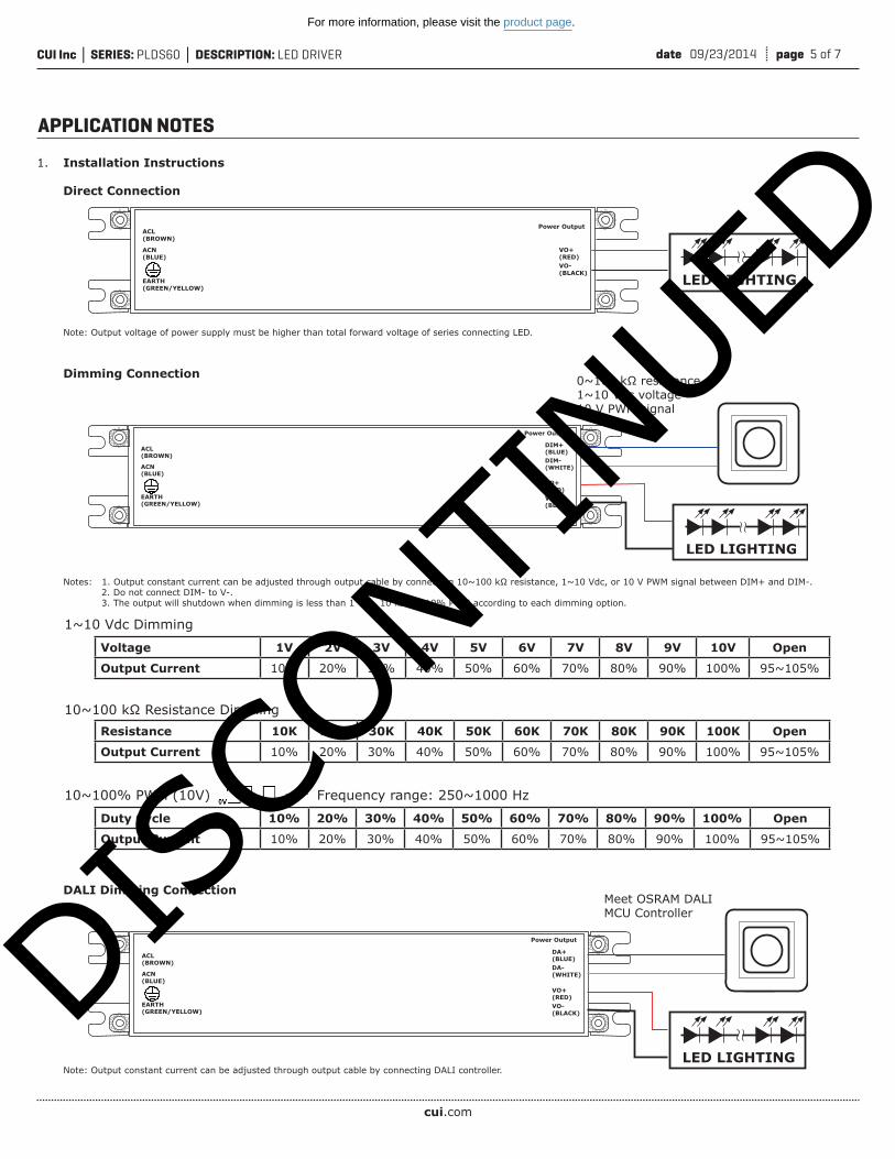
1. Installation Instructions Direct Connection Note: Output voltage of power supply must be higher than total forward voltage of series connecting LED. Dimming Connection Notes: 1. Output constant current can be adjusted through output cable by connecting 10~100 kΩ resistance, 1~10 Vdc, or 10 V PWM signal between DIM+ and DIM-. 2. Do not connect DIM- to V-. 3. The output will shutdown when dimming is less than 1 Vdc, 10 kΩ, or 10% PWM according to each dimming option. DALI Dimming Connection Note: Output constant current can be adjusted through output cable by connecting DALI controller.

APPLICATION NOTES

Resistance 10K 20K 30K 40K 50K 60K 70K 80K 90K 100K Open

Output Current 10% 20% 30% 40% 50% 60% 70% 80% 90% 100% 95~105%

Voltage 1V 2V 3V 4V 5V 6V 7V 8V 9V 10V Open

Output Current 10% 20% 30% 40% 50% 60% 70% 80% 90% 100% 95~105%

Duty Cycle 10% 20% 30% 40% 50% 60% 70% 80% 90% 100% Open

Output Current 10% 20% 30% 40% 50% 60% 70% 80% 90% 100% 95~105%

10~100 kΩ Resistance Dimming

1~10 Vdc Dimming

10~100% PWM (10V) Frequency range: 250~1000 Hz

LED LIGHTING

ACL(BROWN)

Power Output

VO+(RED)VO-(BLACK)

ACN(BLUE)

EARTH(GREEN/YELLOW)

LED LIGHTING

ACL(BROWN)

Power Output

VO+(RED)VO-(BLACK)

DIM+(BLUE)DIM-(WHITE)ACN

(BLUE)

EARTH(GREEN/YELLOW)

0~100 kΩ resistance1~10 Vdc voltage10 V PWM signal

Meet OSRAM DALI MCU Controller

DISCO

NTINUE

D

For more information, please visit the product page.

cui.com

date 09/23/2014 page 6 of 7CUI Inc SERIES: PLDS60 DESCRIPTION: LED DRIVER

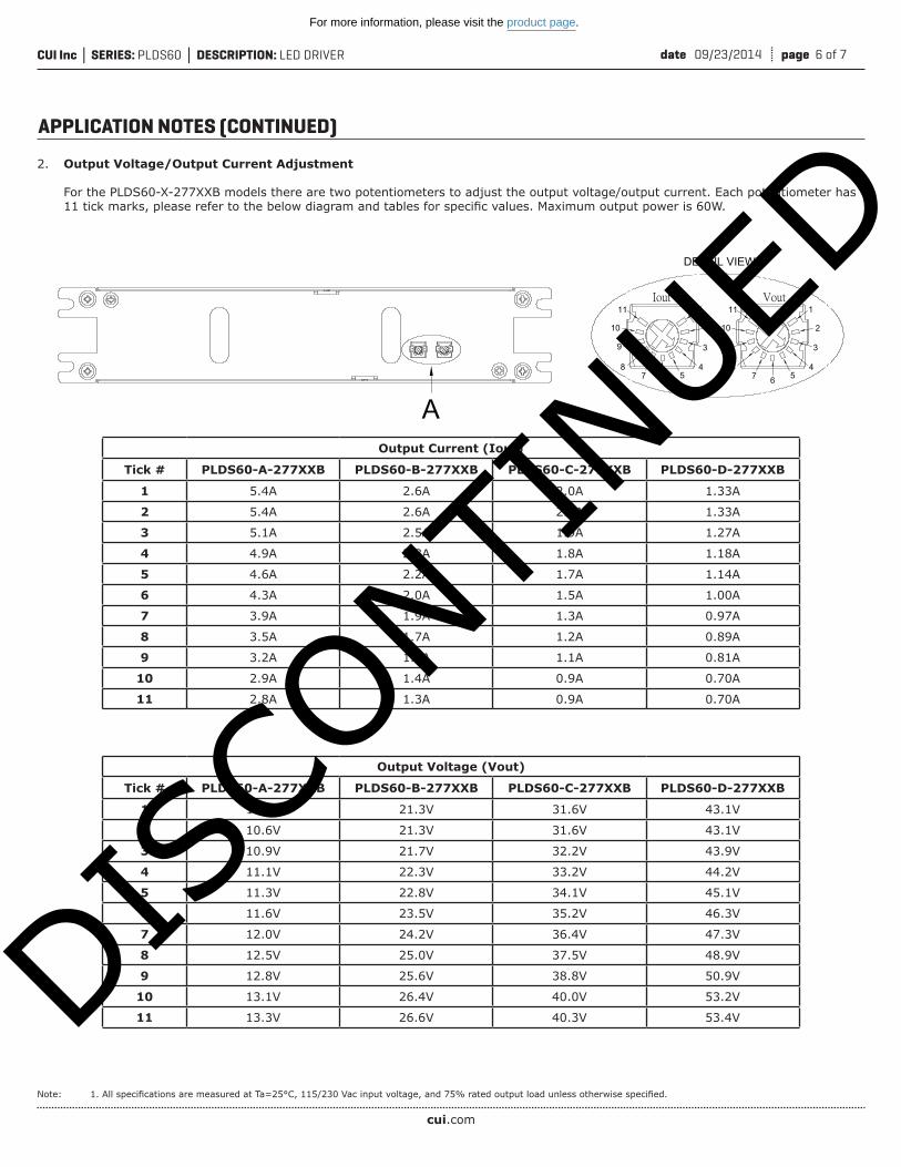
2. Output Voltage/Output Current Adjustment For the PLDS60-X-277XXB models there are two potentiometers to adjust the output voltage/output current. Each potentiometer has 11 tick marks, please refer to the below diagram and tables for specific values. Maximum output power is 60W.

Note: 1. All specifications are measured at Ta=25°C, 115/230 Vac input voltage, and 75% rated output load unless otherwise specified.

APPLICATION NOTES (CONTINUED)

A

A DETAIL VIEW

11

10

9

87 6

1

2

3

45

11

10

9

87 6

1

2

3

45

Output Current (Iout)

Tick # PLDS60-A-277XXB PLDS60-B-277XXB PLDS60-C-277XXB PLDS60-D-277XXB

1 5.4A 2.6A 2.0A 1.33A

2 5.4A 2.6A 2.0A 1.33A

3 5.1A 2.5A 1.9A 1.27A

4 4.9A 2.3A 1.8A 1.18A

5 4.6A 2.2A 1.7A 1.14A

6 4.3A 2.0A 1.5A 1.00A

7 3.9A 1.9A 1.3A 0.97A

8 3.5A 1.7A 1.2A 0.89A

9 3.2A 1.6A 1.1A 0.81A

10 2.9A 1.4A 0.9A 0.70A

11 2.8A 1.3A 0.9A 0.70A

Output Voltage (Vout)

Tick # PLDS60-A-277XXB PLDS60-B-277XXB PLDS60-C-277XXB PLDS60-D-277XXB

1 10.6V 21.3V 31.6V 43.1V

2 10.6V 21.3V 31.6V 43.1V

3 10.9V 21.7V 32.2V 43.9V

4 11.1V 22.3V 33.2V 44.2V

5 11.3V 22.8V 34.1V 45.1V

6 11.6V 23.5V 35.2V 46.3V

7 12.0V 24.2V 36.4V 47.3V

8 12.5V 25.0V 37.5V 48.9V

9 12.8V 25.6V 38.8V 50.9V

10 13.1V 26.4V 40.0V 53.2V

11 13.3V 26.6V 40.3V 53.4VDISCO

NTINUE

D

For more information, please visit the product page.

date 09/23/2014 page 7 of 7CUI Inc SERIES: PLDS60 DESCRIPTION: LED DRIVER

CUI offers a two (2) year limited warranty. Complete warranty information is listed on our website.

CUI reserves the right to make changes to the product at any time without notice. Information provided by CUI is believed to be accurate and reliable. However, no responsibility is assumed by CUI for its use, nor for any infringements of patents or other rights of third parties which may result from its use.

CUI products are not authorized or warranted for use as critical components in equipment that requires an extremely high level of reliability. A critical component is any component of a life support device or system whose failure to perform can be reasonably expected to cause the failure of the life support device or system, or to affect its safety or effectiveness.

Headquarters20050 SW 112th Ave.Tualatin, OR 97062800.275.4899

Fax [email protected]

rev. description date

1.0 initial release 09/23/2014The revision history provided is for informational purposes only and is believed to be accurate.

REVISION HISTORY

DISCO

NTINUE

D

For more information, please visit the product page.


Recommended