SOP STANDARD OPERATING PROCEDURES In accordance with the American with Disabilities Act, an alternative form of communication is available. upon request. TDD: 1-800-627-3529. MDA is an equal opportunity employer and provider.
Transcript
SOP STANDARD OPERATING
PROCEDURES
In accordance with the American with Disabilities Act, an alternative form of communication is available.
upon request. TDD: 1-800-627-3529. MDA is an equal opportunity employer and provider.
Minnesota Department of Agriculture 625 Robert Street North
Saint Paul, Minnesota 55155-4194 http://www.mda.state.mn.us
651-201-6000 or 800-967-2174
Authors and Contributors:
Katie Rassmussen Hydrologist
Scott Matteson
Hydrologist
Minnesota Department of Agriculture Pesticide and Fertilizer Management Division
Monitoring and Assessment Unit
Report Review: Heather Johnson (MDA) Bill VanRyswyk (MDA)
Adam Birr (MDA) Dave Tollefson (MDA) Tim Radatz (MAWRC)
Acronyms and Abbreviations
cfs Cubic Feet per Second (ft3/sec)
CoC Chain of Custody
CSG Crest Stage Gage
CST Central Standard Time
degF Degrees Fahrenheit
MAWRC Minnesota Agricultural Water Resources Coalition
MDA Minnesota Department of Agriculture
MS Measured Stage
MVTL Minnesota Valley Testing Laboratory
RP Reference Point
SOP Standard Operating Procedure
t-tube Transparency Tube
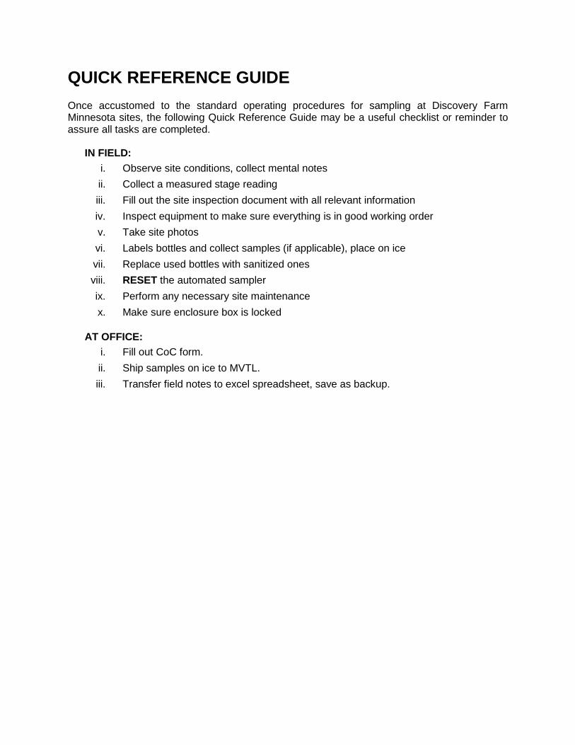
QUICK REFERENCE GUIDE
Once accustomed to the standard operating procedures for sampling at Discovery Farm Minnesota sites, the following Quick Reference Guide may be a useful checklist or reminder to assure all tasks are completed.
IN FIELD:
i. Observe site conditions, collect mental notes
ii. Collect a measured stage reading
iii. Fill out the site inspection document with all relevant information
iv. Inspect equipment to make sure everything is in good working order
v. Take site photos
vi. Labels bottles and collect samples (if applicable), place on ice
vii. Replace used bottles with sanitized ones
viii. RESET the automated sampler
ix. Perform any necessary site maintenance
x. Make sure enclosure box is locked
AT OFFICE:
i. Fill out CoC form.
ii. Ship samples on ice to MVTL.
iii. Transfer field notes to excel spreadsheet, save as backup.
Table of Contents
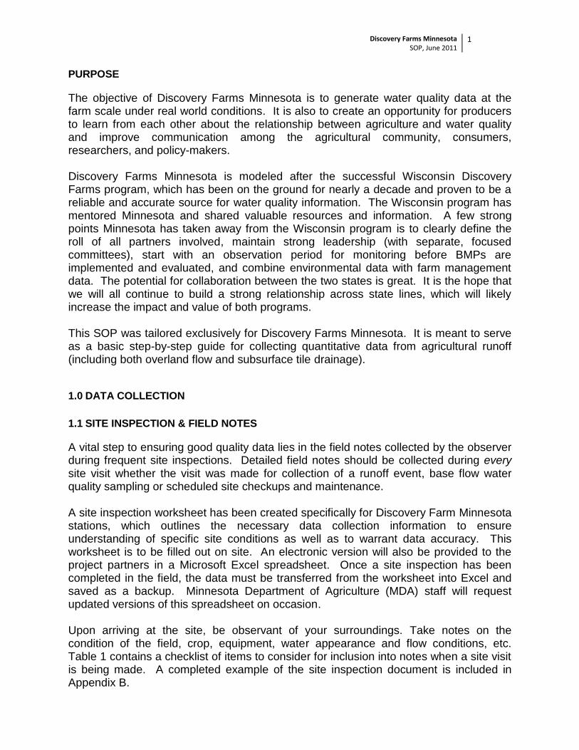
PURPOSE …………………………………………………………………………………………………… 1
1.0 DATA COLLECTION …………………………………………………..………………………………. 1
1.1 Site Inspection and Field Notes ………………………………………………………..…… 1
1.2 Field Measurements ………………………………………………………………………..... 3
4.0 DATA MANAGEMENT AND ANALYSIS ……………………………………………………………. 24
4.1 Data Collection and Storage ………………………………………………………………... 24
4.2 Water Quantity Data …………………………………………………………………………. 24
4.3 Water Quality Data …………………………………………………………………………… 26
4.4 Water Quality Analysis ………………………………………………………………………. 26
4.5 Meteorological Data ………………………………………………………………………….. 26
4.6 Soil Moisture and Temperature ……………………………………………………………. 26
4.7 Data Storage and Submittal ………………………………………………………………… 27
APPENDIX
A. Project Contact Information ………………………………………………………………… 28
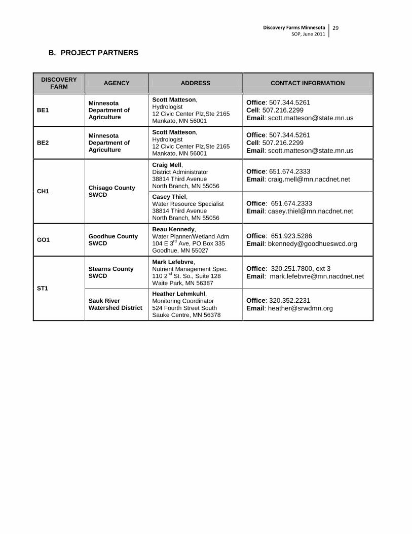
B. Project Partners …………………………………………………………………………...… 29
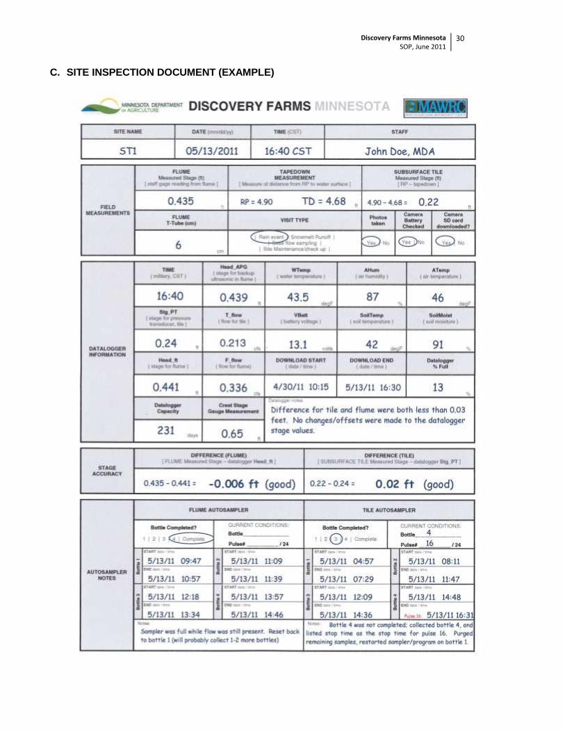
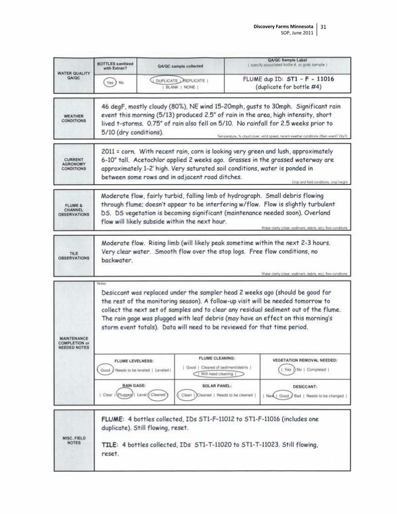
C. Site Inspection Document – Example ……………………………………….……………. 30
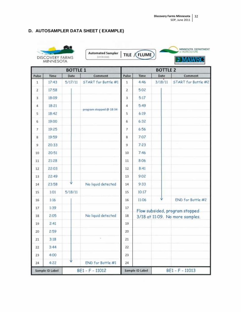
D. Autosampler Data Sheet – Example ……………………………………………………… 32
E. Manual Rain Gauge – Field Data Sheet – Example …………………………………….. 33
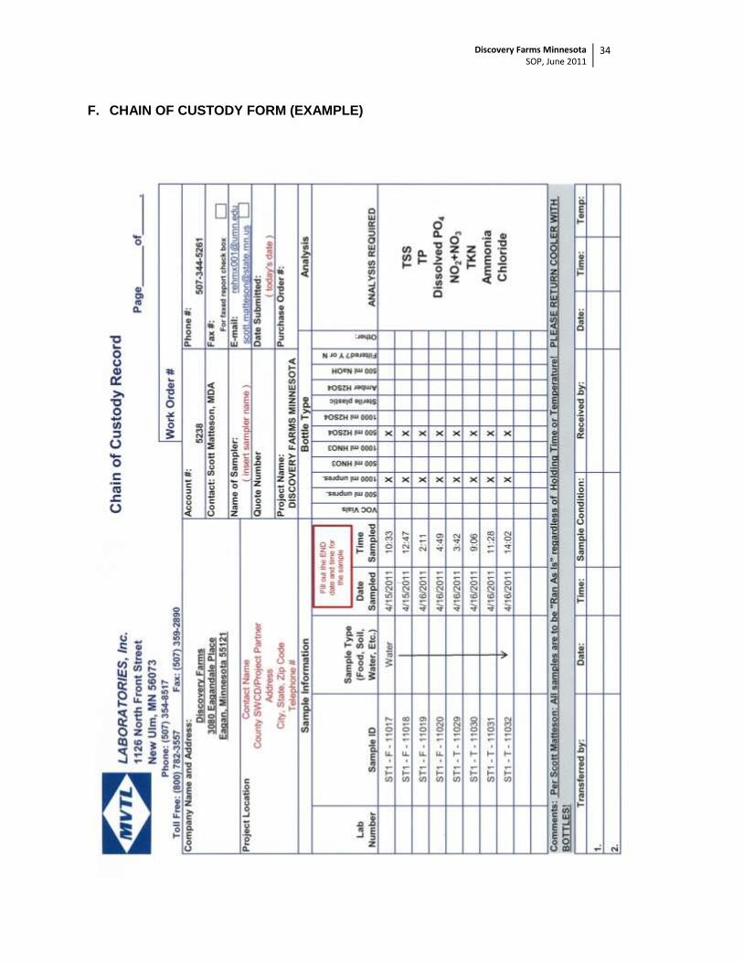
F. MVTL Chain of Custody – Example …………………………………………………...….. 34
Discovery Farms Minnesota SOP, June 2011
1
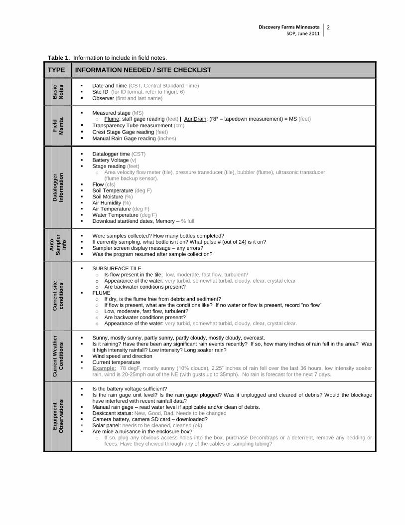
PURPOSE
The objective of Discovery Farms Minnesota is to generate water quality data at the farm scale under real world conditions. It is also to create an opportunity for producers to learn from each other about the relationship between agriculture and water quality and improve communication among the agricultural community, consumers, researchers, and policy-makers. Discovery Farms Minnesota is modeled after the successful Wisconsin Discovery Farms program, which has been on the ground for nearly a decade and proven to be a reliable and accurate source for water quality information. The Wisconsin program has mentored Minnesota and shared valuable resources and information. A few strong points Minnesota has taken away from the Wisconsin program is to clearly define the roll of all partners involved, maintain strong leadership (with separate, focused committees), start with an observation period for monitoring before BMPs are implemented and evaluated, and combine environmental data with farm management data. The potential for collaboration between the two states is great. It is the hope that we will all continue to build a strong relationship across state lines, which will likely increase the impact and value of both programs. This SOP was tailored exclusively for Discovery Farms Minnesota. It is meant to serve as a basic step-by-step guide for collecting quantitative data from agricultural runoff (including both overland flow and subsurface tile drainage). 1.0 DATA COLLECTION
1.1 SITE INSPECTION & FIELD NOTES
A vital step to ensuring good quality data lies in the field notes collected by the observer during frequent site inspections. Detailed field notes should be collected during every site visit whether the visit was made for collection of a runoff event, base flow water quality sampling or scheduled site checkups and maintenance. A site inspection worksheet has been created specifically for Discovery Farm Minnesota stations, which outlines the necessary data collection information to ensure understanding of specific site conditions as well as to warrant data accuracy. This worksheet is to be filled out on site. An electronic version will also be provided to the project partners in a Microsoft Excel spreadsheet. Once a site inspection has been completed in the field, the data must be transferred from the worksheet into Excel and saved as a backup. Minnesota Department of Agriculture (MDA) staff will request updated versions of this spreadsheet on occasion. Upon arriving at the site, be observant of your surroundings. Take notes on the condition of the field, crop, equipment, water appearance and flow conditions, etc. Table 1 contains a checklist of items to consider for inclusion into notes when a site visit is being made. A completed example of the site inspection document is included in Appendix B.
Discovery Farms Minnesota SOP, June 2011
2
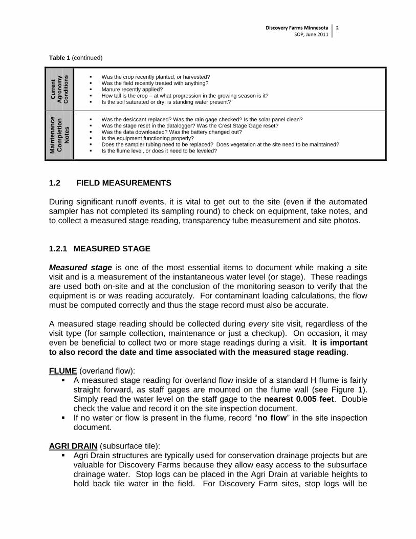
Table 1. Information to include in field notes.
TYPE INFORMATION NEEDED / SITE CHECKLIST
Basic
No
tes
Date and Time (CST, Central Standard Time) Site ID (for ID format, refer to Figure 6)
Observer (first and last name)
Fie
ld
Ms
mts
.
Measured stage (MS) o Flume: staff gage reading (feet) | AgriDrain: (RP – tapedown measurement) = MS (feet)
Datalogger time (CST) Battery Voltage (v) Stage reading (feet)
o Area velocity flow meter (tile), pressure transducer (tile), bubbler (flume), ultrasonic transducer (flume backup sensor).
Flow (cfs) Soil Temperature (deg F) Soil Moisture (%) Air Humidity (%) Air Temperature (deg F) Water Temperature (deg F) Download start/end dates, Memory -- % full
Au
to
Sam
ple
r
info
Were samples collected? How many bottles completed? If currently sampling, what bottle is it on? What pulse # (out of 24) is it on? Sampler screen display message – any errors? Was the program resumed after sample collection?
Cu
rren
t sit
e
co
nd
itio
ns
SUBSURFACE TILE o Is flow present in the tile: low, moderate, fast flow, turbulent? o Appearance of the water: very turbid, somewhat turbid, cloudy, clear, crystal clear o Are backwater conditions present?
FLUME o If dry, is the flume free from debris and sediment? o If flow is present, what are the conditions like? If no water or flow is present, record “no flow” o Low, moderate, fast flow, turbulent? o Are backwater conditions present? o Appearance of the water: very turbid, somewhat turbid, cloudy, clear, crystal clear.
Cu
rren
t W
eath
er
Co
nd
itio
ns
Sunny, mostly sunny, partly sunny, partly cloudy, mostly cloudy, overcast. Is it raining? Have there been any significant rain events recently? If so, how many inches of rain fell in the area? Was
it high intensity rainfall? Low intensity? Long soaker rain? Wind speed and direction Current temperature Example: 78 degF, mostly sunny (10% clouds), 2.25” inches of rain fell over the last 36 hours, low intensity soaker
rain, wind is 20-25mph out of the NE (with gusts up to 35mph). No rain is forecast for the next 7 days.
Eq
uip
men
t
Ob
serv
ati
on
s
Is the battery voltage sufficient? Is the rain gage unit level? Is the rain gage plugged? Was it unplugged and cleared of debris? Would the blockage
have interfered with recent rainfall data? Manual rain gage – read water level if applicable and/or clean of debris. Desiccant status: New, Good, Bad, Needs to be changed Camera battery, camera SD card – downloaded? Solar panel: needs to be cleaned, cleaned (ok) Are mice a nuisance in the enclosure box?
o If so, plug any obvious access holes into the box, purchase Decon/traps or a deterrent, remove any bedding or feces. Have they chewed through any of the cables or sampling tubing?
Discovery Farms Minnesota SOP, June 2011
3
Table 1 (continued) C
urr
en
t
Ag
ron
om
y
Co
nd
itio
ns
Was the crop recently planted, or harvested? Was the field recently treated with anything? Manure recently applied? How tall is the crop – at what progression in the growing season is it? Is the soil saturated or dry, is standing water present?
Ma
inte
na
nce
Co
mp
leti
on
No
tes
Was the desiccant replaced? Was the rain gage checked? Is the solar panel clean? Was the stage reset in the datalogger? Was the Crest Stage Gage reset? Was the data downloaded? Was the battery changed out? Is the equipment functioning properly? Does the sampler tubing need to be replaced? Does vegetation at the site need to be maintained? Is the flume level, or does it need to be leveled?
1.2 FIELD MEASUREMENTS During significant runoff events, it is vital to get out to the site (even if the automated sampler has not completed its sampling round) to check on equipment, take notes, and to collect a measured stage reading, transparency tube measurement and site photos. 1.2.1 MEASURED STAGE Measured stage is one of the most essential items to document while making a site visit and is a measurement of the instantaneous water level (or stage). These readings are used both on-site and at the conclusion of the monitoring season to verify that the equipment is or was reading accurately. For contaminant loading calculations, the flow must be computed correctly and thus the stage record must also be accurate. A measured stage reading should be collected during every site visit, regardless of the visit type (for sample collection, maintenance or just a checkup). On occasion, it may even be beneficial to collect two or more stage readings during a visit. It is important to also record the date and time associated with the measured stage reading.
FLUME (overland flow): A measured stage reading for overland flow inside of a standard H flume is fairly
straight forward, as staff gages are mounted on the flume wall (see Figure 1). Simply read the water level on the staff gage to the nearest 0.005 feet. Double check the value and record it on the site inspection document.
If no water or flow is present in the flume, record “no flow” in the site inspection document.
AGRI DRAIN (subsurface tile):
Agri Drain structures are typically used for conservation drainage projects but are valuable for Discovery Farms because they allow easy access to the subsurface drainage water. Stop logs can be placed in the Agri Drain at variable heights to hold back tile water in the field. For Discovery Farm sites, stop logs will be
Discovery Farms Minnesota SOP, June 2011
4
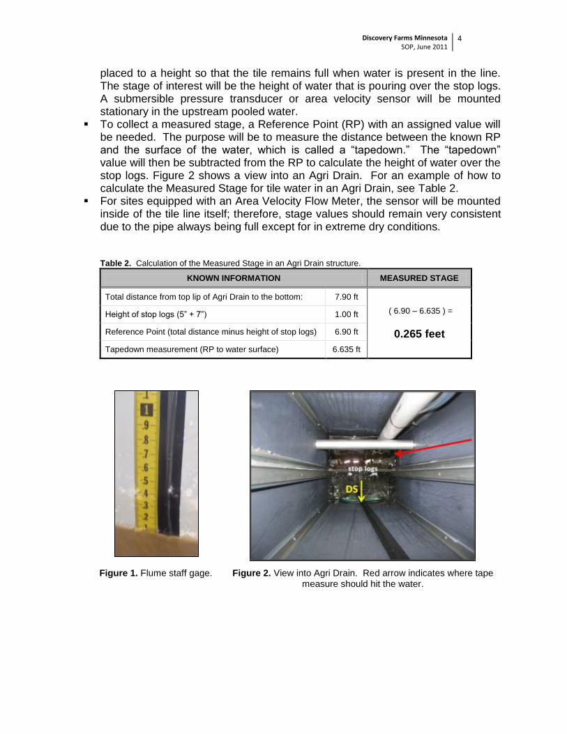
placed to a height so that the tile remains full when water is present in the line. The stage of interest will be the height of water that is pouring over the stop logs. A submersible pressure transducer or area velocity sensor will be mounted stationary in the upstream pooled water.
To collect a measured stage, a Reference Point (RP) with an assigned value will be needed. The purpose will be to measure the distance between the known RP and the surface of the water, which is called a “tapedown.” The “tapedown” value will then be subtracted from the RP to calculate the height of water over the stop logs. Figure 2 shows a view into an Agri Drain. For an example of how to calculate the Measured Stage for tile water in an Agri Drain, see Table 2.
For sites equipped with an Area Velocity Flow Meter, the sensor will be mounted inside of the tile line itself; therefore, stage values should remain very consistent due to the pipe always being full except for in extreme dry conditions. Table 2. Calculation of the Measured Stage in an Agri Drain structure.
KNOWN INFORMATION MEASURED STAGE
Total distance from top lip of Agri Drain to the bottom: 7.90 ft
( 6.90 – 6.635 ) =
0.265 feet
Height of stop logs (5” + 7”) 1.00 ft
Reference Point (total distance minus height of stop logs) 6.90 ft
Tapedown measurement (RP to water surface) 6.635 ft
Figure 1. Flume staff gage. Figure 2. View into Agri Drain. Red arrow indicates where tape measure should hit the water.
Discovery Farms Minnesota SOP, June 2011
5
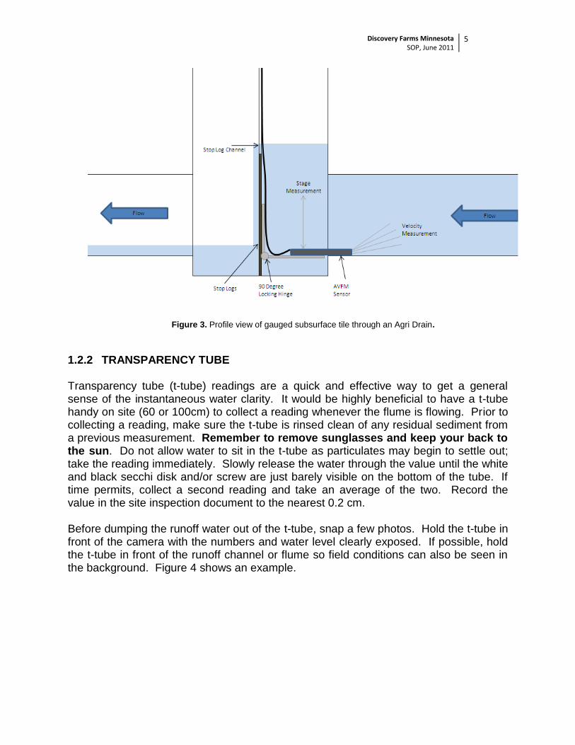
Figure 3. Profile view of gauged subsurface tile through an Agri Drain.
1.2.2 TRANSPARENCY TUBE
Transparency tube (t-tube) readings are a quick and effective way to get a general sense of the instantaneous water clarity. It would be highly beneficial to have a t-tube handy on site (60 or 100cm) to collect a reading whenever the flume is flowing. Prior to collecting a reading, make sure the t-tube is rinsed clean of any residual sediment from a previous measurement. Remember to remove sunglasses and keep your back to the sun. Do not allow water to sit in the t-tube as particulates may begin to settle out; take the reading immediately. Slowly release the water through the value until the white and black secchi disk and/or screw are just barely visible on the bottom of the tube. If time permits, collect a second reading and take an average of the two. Record the value in the site inspection document to the nearest 0.2 cm. Before dumping the runoff water out of the t-tube, snap a few photos. Hold the t-tube in front of the camera with the numbers and water level clearly exposed. If possible, hold the t-tube in front of the runoff channel or flume so field conditions can also be seen in the background. Figure 4 shows an example.
Discovery Farms Minnesota SOP, June 2011
6
Figure 4. Transparency tube photos during runoff.
1.2.3 SITE PHOTOS
Field cameras are installed at each of the Discovery Farm sites and are programmed to take a photo each day and during runoff events (see Section 2.9 for further description). These cameras are stationary and will be installed downstream from the flume. Stationary photos are excellent for showing the changes in the field conditions over time from winter snow conditions, snowmelt runoff, rain events, canopy development, drought and even fall harvest. Stationary photos, however, do not showcase the entire picture. Although photos are being collected on a daily basis, it is strongly recommended that photos be collected by the observer during site visits; the more the better. Table 3 provides of list for potential photos of interest.
SITE PHOTOS
Upstream Field
Downstream channel
Overview of flume
View of entire flume with water exiting
Overview of entire monitoring site
Equipment photo
Photo of full sample bottles (mixed well)
T-tube photo with flume in the background
Tile runoff / Agri Drain
Crest Stage Gage pictures
Before and after photo of flume cleaning or
vegetation removal
Table 3. Photos of interest to collect during site visits.
Figure 5. Examples of site photos.
Discovery Farms Minnesota SOP, June 2011
7
MDA staff will request copies of all relevant photos periodically. Please save photos under the following format: Date_SiteID_Type. The date should be in the format mm-dd-yy. The photo “type” should include a descriptive comment (“SnowmeltRunoff”, “US” (upstream), or “DS” (downstream), “RainEvent”, “Field”, “Flume”, etc). If multiple photos (>5) exist for one field visit, use the format Date_SiteID for simplicity and then number the photos according to the time they were taken.
For example: 03-15-11_GO1_SnowmeltRunoff.jpg 05-14-11_BE1_RainEvent_US.jpg 05-14-11_BE1_RainEvent_US1.jpg 08-09-11_CH1_RainEvent_Ttube.jpg Multiple photos: 03-15-11_GO1 (1).jpg to 03-15-11_GO1 (12).jpg
1.3 SAMPLE COLLECTION AND PROCESSING
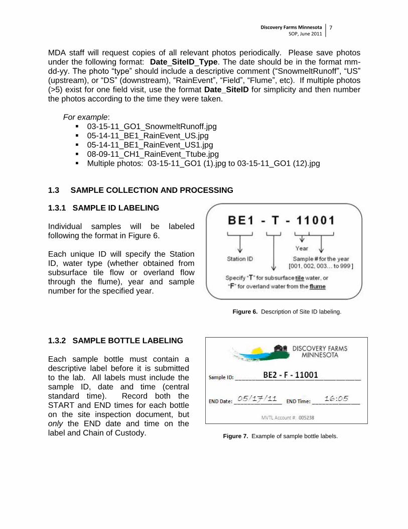
1.3.1 SAMPLE ID LABELING Individual samples will be labeled following the format in Figure 6. Each unique ID will specify the Station ID, water type (whether obtained from subsurface tile flow or overland flow through the flume), year and sample number for the specified year.
Figure 6. Description of Site ID labeling.
1.3.2 SAMPLE BOTTLE LABELING Each sample bottle must contain a descriptive label before it is submitted to the lab. All labels must include the sample ID, date and time (central standard time). Record both the START and END times for each bottle on the site inspection document, but only the END date and time on the label and Chain of Custody.
Figure 7. Example of sample bottle labels.
Discovery Farms Minnesota SOP, June 2011
8
1.3.3 SAMPLER KEYPAD BASICS
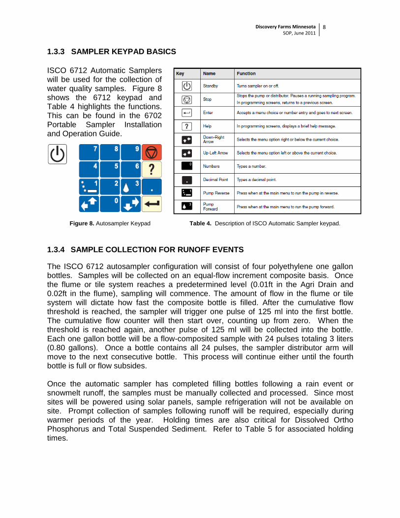
ISCO 6712 Automatic Samplers will be used for the collection of water quality samples. Figure 8 shows the 6712 keypad and Table 4 highlights the functions. This can be found in the 6702 Portable Sampler Installation and Operation Guide.
Figure 8. Autosampler Keypad
Table 4. Description of ISCO Automatic Sampler keypad.
1.3.4 SAMPLE COLLECTION FOR RUNOFF EVENTS
The ISCO 6712 autosampler configuration will consist of four polyethylene one gallon bottles. Samples will be collected on an equal-flow increment composite basis. Once the flume or tile system reaches a predetermined level (0.01ft in the Agri Drain and 0.02ft in the flume), sampling will commence. The amount of flow in the flume or tile system will dictate how fast the composite bottle is filled. After the cumulative flow threshold is reached, the sampler will trigger one pulse of 125 ml into the first bottle. The cumulative flow counter will then start over, counting up from zero. When the threshold is reached again, another pulse of 125 ml will be collected into the bottle. Each one gallon bottle will be a flow-composited sample with 24 pulses totaling 3 liters (0.80 gallons). Once a bottle contains all 24 pulses, the sampler distributor arm will move to the next consecutive bottle. This process will continue either until the fourth bottle is full or flow subsides. Once the automatic sampler has completed filling bottles following a rain event or snowmelt runoff, the samples must be manually collected and processed. Since most sites will be powered using solar panels, sample refrigeration will not be available on site. Prompt collection of samples following runoff will be required, especially during warmer periods of the year. Holding times are also critical for Dissolved Ortho Phosphorus and Total Suspended Sediment. Refer to Table 5 for associated holding times.
Discovery Farms Minnesota SOP, June 2011
9
STEPS FOR RUNOFF SAMPLE COLLECTION:
i. Record the display message on the autosampler head in the field notes. Specify the number of completed bottles or any errors that occurred. If the sampler is still collecting, record the current bottle number and pulse.
a. If any error messages are displayed, troubleshoot the equipment to fix the error. Call an MDA Discovery Farms representative if you have any questions.
ii. If a program is already running, you will need to stop the program
by hitting the (stop) button. This will push the program into a manual pause.
iii. The main screen has four options: RUN, PROGRAM, VIEW REPORT, OTHER FUNCTIONS. Arrow down to VIEW
REPORT, hit the enter button , select VIEW DATA from the next menu. Then, select SAMPLING REPORT from the third menu.
a. VIEW REPORT VIEW DATA SAMPLING REPORT.
iv. Once SAMPLING REPORT is selected, the sampler will run through the program sampling details, including start and stop times for each of the 24 pulses for bottles 1, 2, 3 and 4. The arrow keys can be used to toggle back and forth if a day or time is missed.
a. Document any errors that occur for each pulse, such as “no liquid detected” with the associated date and time.
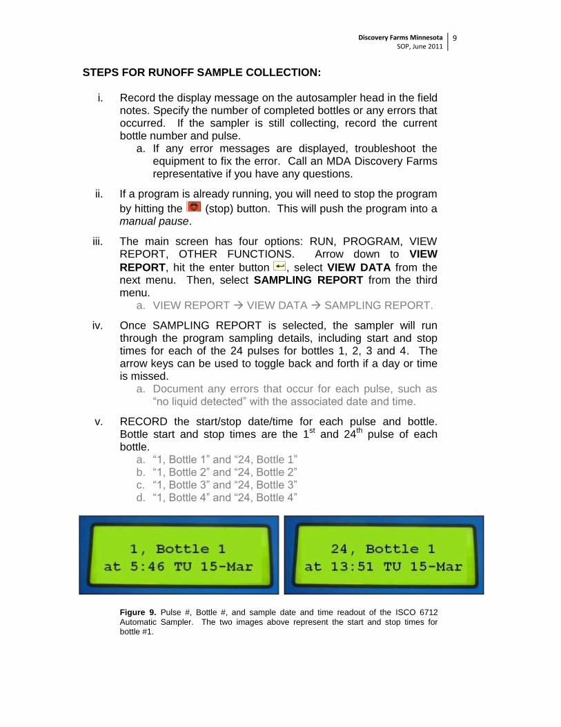
v. RECORD the start/stop date/time for each pulse and bottle. Bottle start and stop times are the 1st and 24th pulse of each bottle.
a. “1, Bottle 1” and “24, Bottle 1” b. “1, Bottle 2” and “24, Bottle 2” c. “1, Bottle 3” and “24, Bottle 3” d. “1, Bottle 4” and “24, Bottle 4”
Figure 9. Pulse #, Bottle #, and sample date and time readout of the ISCO 6712
Automatic Sampler. The two images above represent the start and stop times for bottle #1.
Discovery Farms Minnesota SOP, June 2011
10
vi. If the sampler stopped collecting water before a bottle was completely filled, take the end date/time for the last pulse number collected. For example, if Bottle 3 only collected 17 pulses (out of 24), the start/stop time that would need to be recorded for that bottle would be listed under “1, Bottle 3” and “17, Bottle 3.”
vii. Prepare and label the needed MVTL sample bottles. Two labels with the same ID, and two MVTL bottles will be needed for each one gallon sampler bottle.
a. 1 Liter (unpreserved) b. 500mL (preserved with H2SO4)
viii. Ensure the sampler head is fastened securely (three separate latches), then carefully remove the automatic sampler from the metal enclosure box and set it on the ground. Unfasten the latches and place the sampler head back up inside the enclosure box.
ix. Make sure to identify which bottle is which -- 1, 2, 3 and 4.
x. Nitrile or protective gloves should be worn when handling water quality samples.
xi. Screw the lids tightly onto the one gallon sample bottles. Aggressively shake each one gallon sampler bottle individually for at least 30-60 seconds, making sure to invert the bottle numerous times. It is very important to adequately agitate the sample to assure that sediment particles have been evenly distributed.
xii. Upon shaking, immediately pour the representative sample into the appropriate labeled 500ml and 1L bottles.
xiii. Once the appropriate samples have been collected, immediately place bottles into a cooler, on ice.
xiv. Used one gallon bottles must be taken back to the office to be rinsed and sanitized using a strong concentrated cleaning solution before being used again. A second full set of one gallon sample bottles should be provided for each monitoring station to allow for swapping out sanitized/dirty bottles. Please refer to Section 2.2 for the bottle washing procedure.
xv. IMPORTANT: To prepare the sampler for the next runoff event, it will need to be reset (or resumed) so that the program can start
over again. Click on the (stop) button, and toggle to either RUN (or RESUME PROGRAM).
a. RESUME PROGRAM will restart the sampler from the last bottle and pulse number that the sampler was on before the manual pause.
Discovery Farms Minnesota SOP, June 2011
11
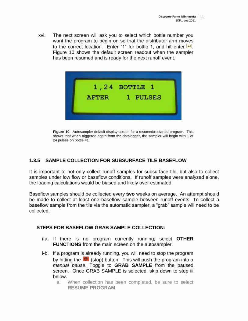
xvi. The next screen will ask you to select which bottle number you want the program to begin on so that the distributor arm moves
to the correct location. Enter “1” for bottle 1, and hit enter . Figure 10 shows the default screen readout when the sampler has been resumed and is ready for the next runoff event.
Figure 10. Autosampler default display screen for a resumed/restarted program. This
shows that when triggered again from the datalogger, the sampler will begin with 1 of 24 pulses on bottle #1.
1.3.5 SAMPLE COLLECTION FOR SUBSURFACE TILE BASEFLOW It is important to not only collect runoff samples for subsurface tile, but also to collect samples under low flow or baseflow conditions. If runoff samples were analyzed alone, the loading calculations would be biased and likely over estimated. Baseflow samples should be collected every two weeks on average. An attempt should be made to collect at least one baseflow sample between runoff events. To collect a baseflow sample from the tile via the automatic sampler, a “grab” sample will need to be collected.
STEPS FOR BASEFLOW GRAB SAMPLE COLLECTION:
i-a. If there is no program currently running; select OTHER FUNCTIONS from the main screen on the autosampler.
i-b. If a program is already running, you will need to stop the program
by hitting the (stop) button. This will push the program into a manual pause. Toggle to GRAB SAMPLE from the paused screen. Once GRAB SAMPLE is selected, skip down to step iii below.
a. When collection has been completed, be sure to select RESUME PROGRAM.
Discovery Farms Minnesota SOP, June 2011
12
ii. From OTHER FUNCTIONS MANUAL FUNCTIONS GRAB SAMPLE.
iii. Grab an extra one gallon sample bottle, and disconnect the pump tube from the bulkhead fitting. Place the tube over the one gallon bottle.
iv. The screen will prompt you to enter a sample volume (in milliliters). Enter a number between 1500-2000 ml and press the
(enter) button.
v. The sampler will purge the suction line before a sample is collected. The display will read “PUMPING______ml” when the sample is being collected, and will purge again upon completion.
vi. Once the sample is collected, reconnect the pump tube to the bulkhead fitting.
vii. Prepare and label the needed MVTL sample bottles. Two MVTL bottles will be needed for each sample.
a. 1 liter (unpreserved) b. 500 ml (preserved, H2SO4)
viii. Screw the lid tightly onto the one gallon sample bottle. Aggressively shake the bottle for 30 seconds to agitate the sample.
ix. Upon shaking, immediately pour the representative sample into the 500ml and 1L MVTL bottles.
x. Once the grab sample has been collected, immediately place the labeled bottle into a cooler, on ice.
xi. The used one gallon sample bottle must be properly sanitized before it is used again. Refer to Section 2.2 for the bottle washing procedure.
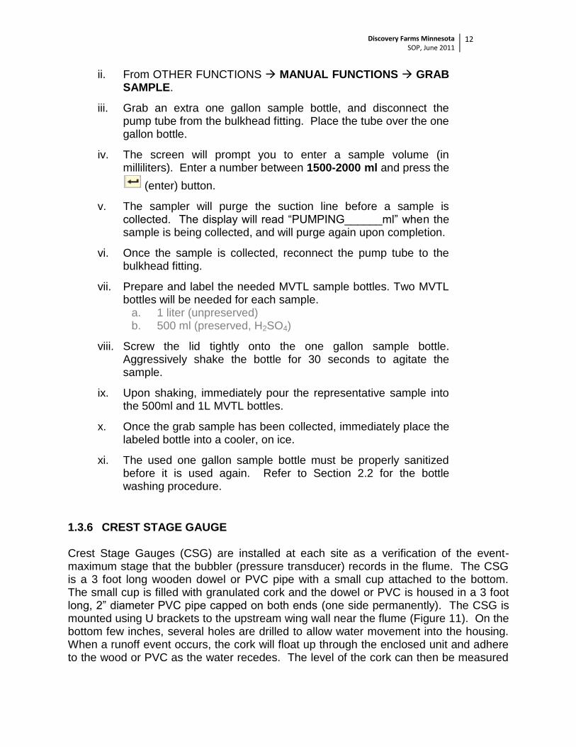
1.3.6 CREST STAGE GAUGE Crest Stage Gauges (CSG) are installed at each site as a verification of the event-maximum stage that the bubbler (pressure transducer) records in the flume. The CSG is a 3 foot long wooden dowel or PVC pipe with a small cup attached to the bottom. The small cup is filled with granulated cork and the dowel or PVC is housed in a 3 foot long, 2” diameter PVC pipe capped on both ends (one side permanently). The CSG is mounted using U brackets to the upstream wing wall near the flume (Figure 11). On the bottom few inches, several holes are drilled to allow water movement into the housing. When a runoff event occurs, the cork will float up through the enclosed unit and adhere to the wood or PVC as the water recedes. The level of the cork can then be measured
Discovery Farms Minnesota SOP, June 2011
13
with a tape measure following a rain event and recorded to the nearest 0.01 feet in the site inspection document. Once a measurement has been gathered, it is suggested to take a photo of the CSG with cork (see Figure 11). Once done, brush off the granulated cork from the dowel or PVC and make sure there is adequate cork remaining in the small cup. A small plastic jar of granulated cork will be kept at each site for refills. The bottom of the CSG will be surveyed in with the bottom of the flume, and an offset will be applied to compare the CSG measurement with the peak bubbler measurement.
.
Figure 11. CSG location on upstream wingwall and cork measurements following a runoff event.
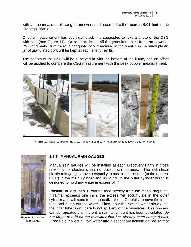
Figure 12. Manual rain gauge.
1.3.7 MANUAL RAIN GAUGES Manual rain gauges will be installed at each Discovery Farm in close proximity to electronic tipping bucket rain gauges. The cylindrical plastic rain gauges have a capacity to measure 1” of rain (to the nearest 0.01”) in the main cylinder and up to 11” in the outer cylinder which is designed to hold any water in excess of 1”. Rainfalls of less than 1” can be read directly from the measuring tube. If rainfall exceeds one inch, the excess will accumulate in the outer cylinder and will need to be manually tallied. Carefully remove the inner tube and dump out the water. Then, pour the excess water slowly into the inner tube taking care to not spill any of the rainwater. This process can be repeated until the entire rain fall amount has been calculated (do not forget to add on the rainwater that has already been dumped out). If possible, collect all rain water into a secondary holding device so that
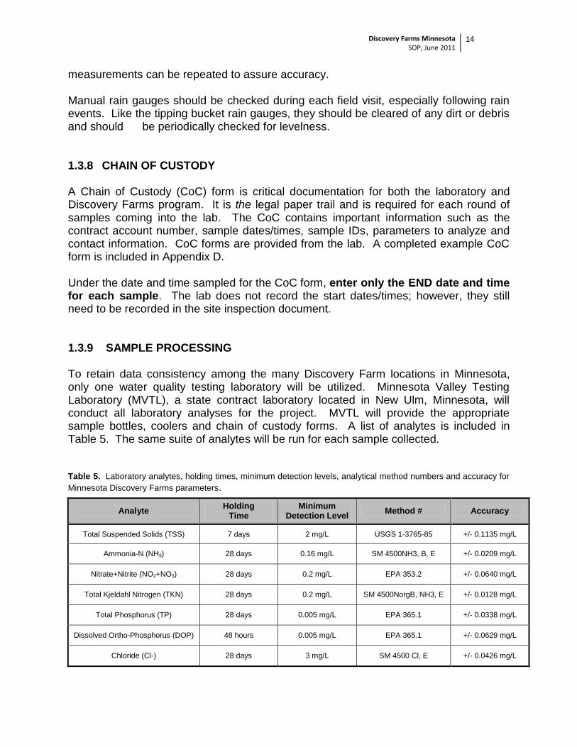
measurements can be repeated to assure accuracy. Manual rain gauges should be checked during each field visit, especially following rain events. Like the tipping bucket rain gauges, they should be cleared of any dirt or debris and should be periodically checked for levelness. 1.3.8 CHAIN OF CUSTODY A Chain of Custody (CoC) form is critical documentation for both the laboratory and Discovery Farms program. It is the legal paper trail and is required for each round of samples coming into the lab. The CoC contains important information such as the contract account number, sample dates/times, sample IDs, parameters to analyze and contact information. CoC forms are provided from the lab. A completed example CoC form is included in Appendix D. Under the date and time sampled for the CoC form, enter only the END date and time for each sample. The lab does not record the start dates/times; however, they still need to be recorded in the site inspection document. 1.3.9 SAMPLE PROCESSING To retain data consistency among the many Discovery Farm locations in Minnesota, only one water quality testing laboratory will be utilized. Minnesota Valley Testing Laboratory (MVTL), a state contract laboratory located in New Ulm, Minnesota, will conduct all laboratory analyses for the project. MVTL will provide the appropriate sample bottles, coolers and chain of custody forms. A list of analytes is included in Table 5. The same suite of analytes will be run for each sample collected. Table 5. Laboratory analytes, holding times, minimum detection levels, analytical method numbers and accuracy for
Minnesota Discovery Farms parameters.
Analyte Holding
Time Minimum
Detection Level Method # Accuracy
Total Suspended Solids (TSS) 7 days 2 mg/L USGS 1-3765-85 +/- 0.1135 mg/L
Ammonia-N (NH3) 28 days 0.16 mg/L SM 4500NH3, B, E +/- 0.0209 mg/L
Chloride (Cl-) 28 days 3 mg/L SM 4500 Cl, E +/- 0.0426 mg/L
Discovery Farms Minnesota SOP, June 2011
15
Immediately following collection, samples must be placed in ice chests (coolers) containing ice or ice substitutes. While transporting samples, ice chests should be cooled to a temperature of four degrees Celsius if possible. A general rule of thumb is “the cooler the better.” During winter months ice or ice substitutes may be unnecessary if the ice chest and vehicle temperatures remain low. Shipment method will be at the discretion of the project partner, however, for ease an account has been set up via Spee-Dee Delivery Service through the Minnesota Agricultural Water Resources Coalition (MAWRC). Efforts should be made get samples to the laboratory within 48 hours to abide by holding times. Samples must be shipped to the address below along with the completed CoC form. The form should be placed in a sealed Ziploc bag during transport to make certain that it does not get wet and lids to the coolers ought to be secured with packaging tape. Once MVTL receives a shipment of samples, they will send the cooler along with a clean set of sample bottles back to the project partner.
Minnesota Valley Testing Laboratory 1126 North Front Street
New Ulm, Minnesota 56073
Phone: (507) 354-8517 or (800) 782-3557
Discovery Farms Minnesota SOP, June 2011
16
2.0 SITE MAINTENANCE
2.1 CALIBRATION OF STAGE As previously mentioned in Section 1.2.3, frequent site visits are important to ensure that the equipment is providing accurate data measurements. Measured Stage (MS) values collected during site visits are crucial for correcting raw data from the bubbler or pressure transducer (via the datalogger). It is possible for a stage sensor to “drift” over time. Drift essentially means that the stage output has slowly drifted from the true value and is reading slightly off. The datalogger is set to calculate flow based on provided equations for the flume and AgriDrain. These equations are heavily reliant on the stage measurements in a calculated area and because of this, it is very important to ensure that the stage readings are as accurate as possible. As a general rule of thumb, if the difference between the MS and the current stage on the datalogger is greater than 0.02 feet, the datalogger stage should be reset to what the current MS is. Prior to resetting any equipment, please verify that your MS value is accurate by taking one or more follow-up measurements. Always include notes in the site inspection document if the datalogger stage has been altered. If the equipment is showing drift repeatedly after being corrected during previous site visits, there may be a bigger issue. Please contact a MDA Discovery Farms representative to discuss these issues.
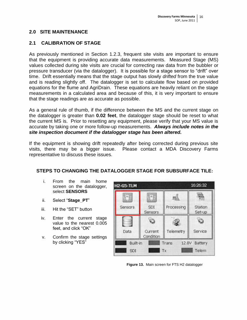
STEPS TO CHANGING THE DATALOGGER STAGE FOR SUBSURFACE TILE:
i. From the main home screen on the datalogger, select SENSORS
ii. Select “Stage_PT”
iii. Hit the “SET” button
iv. Enter the current stage value to the nearest 0.005 feet, and click “OK”
v. Confirm the stage settings by clicking “YES”
Figure 13. Main screen for FTS H2 datalogger
Discovery Farms Minnesota SOP, June 2011
17
2.2 BOTTLE CLEANING
Bottle washing is a necessary step to eliminate sampling bias, reduce sample variability and to produce comparable data. Properly clean and sanitized bottles should be used after every runoff event or when the integrity of the bottles is in question.
Supplies needed: Non-phosphate soap (Extran, a commercial cleaner)
CAUTION: Extran is a strong base and can be corrosive. Caution must be used in handling this product, including eye and skin protection.
Extran Material Safety Data Sheet (MSDS): https://www.vwrsp.com/msds/10/EM-/EM-EX0996-2.pdf
Distilled/De-ionized (DI) water Cleaning brushes (plastic) Cleaning basin (plastic, stainless steel or glass) Nitrile gloves Protective eyewear
Bottles
i. Prepare 1-2% solution of Extran inside of each one gallon sample bottle. 1% solution is equal to approximately 38 ml of Extran, with the rest being water.
ii. Allow the solution to soak for at least 10 minutes. iii. Use a bottle brush to mechanically remove any particles attached to the
bottle. iv. Rinse at least three times with hot tap water, followed by triple rinsing with
de-ionized water. v. Allow bottles to air dry while inverted. vi. Once dry, visually inspect the bottles for spots indicating insufficient washing.
If necessary, repeat process. vii. Cap bottle with a clean lid (see below).
Lids i. Soak caps in 1-2% Extran solution for at least 10 minutes. ii. Mechanically remove any particulate matter. iii. Rinse three times with hot tap water, followed by triple rinsing with de-ionized
water. iv. Allow caps to air dry the place on a clean bottle.
2.3 WINTER MAINTENANCE Winter runoff in Minnesota is infrequent, but it is imperative to keep a keen eye on the weather throughout the winter months and especially prior to snowmelt runoff in early spring. Generally, during winter months it will take a few consecutive days of above-freezing temperatures to generate any runoff. If these conditions are foreseen, it should be top priority to get out and prepare the site for potential runoff. Flumes will drift and fill in with snow over the winter. It is also very possible for ice to accumulate and freeze on the bottom of the flume (sometimes even layers of snow and
Discovery Farms Minnesota SOP, June 2011
18
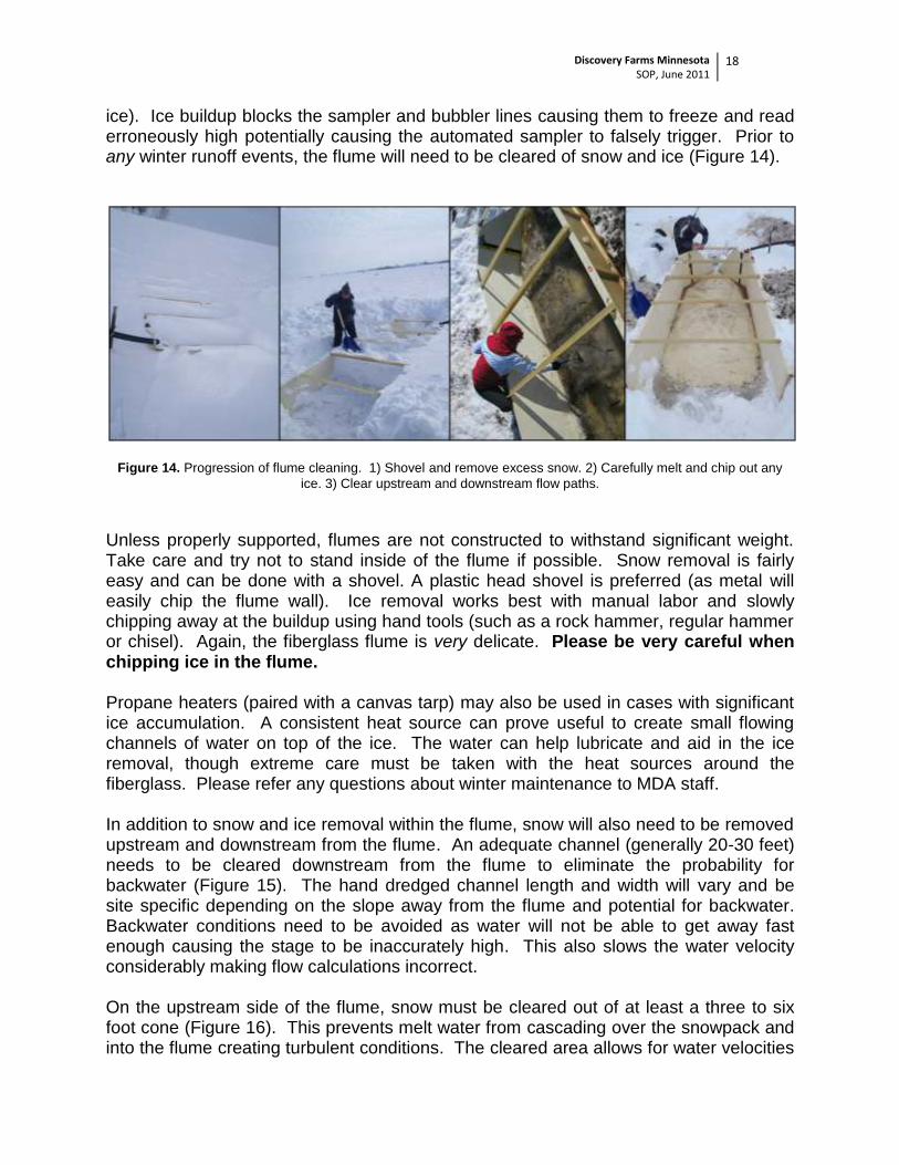
ice). Ice buildup blocks the sampler and bubbler lines causing them to freeze and read erroneously high potentially causing the automated sampler to falsely trigger. Prior to any winter runoff events, the flume will need to be cleared of snow and ice (Figure 14).
Figure 14. Progression of flume cleaning. 1) Shovel and remove excess snow. 2) Carefully melt and chip out any
ice. 3) Clear upstream and downstream flow paths.
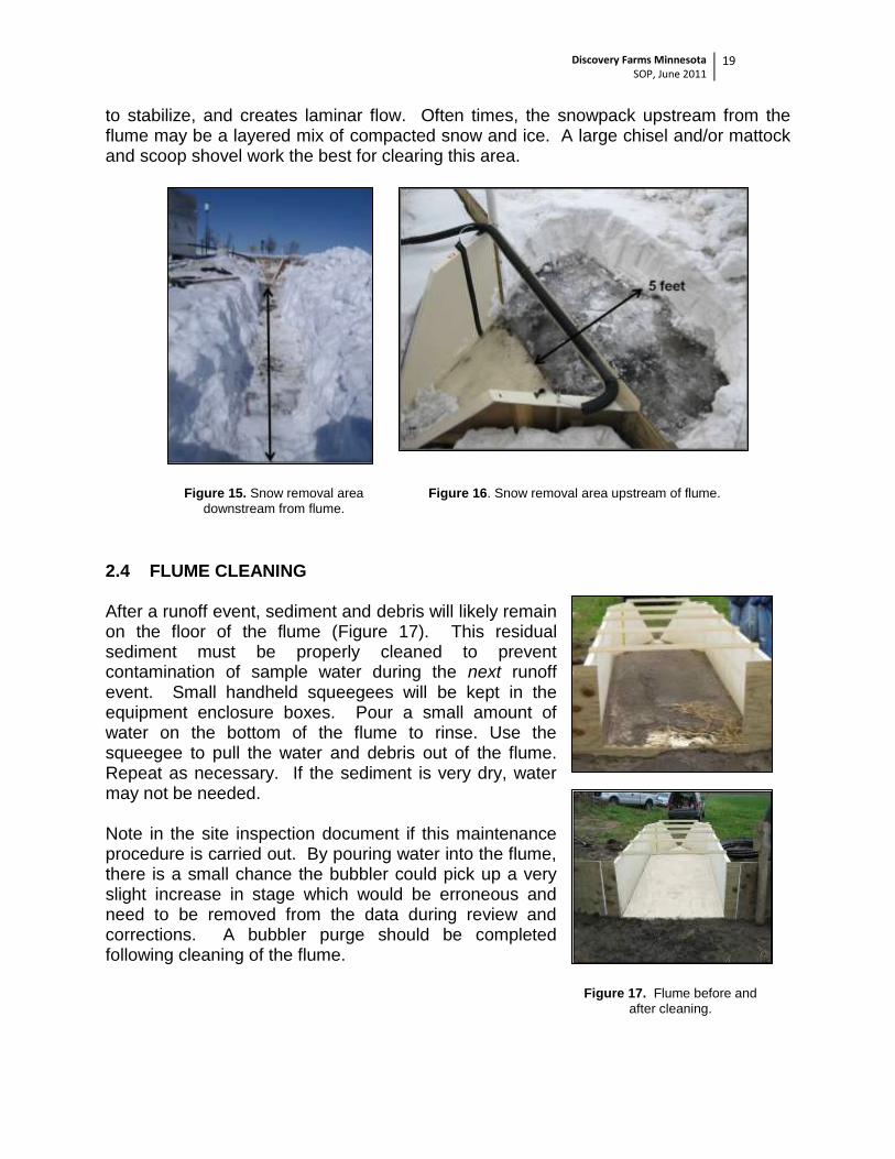
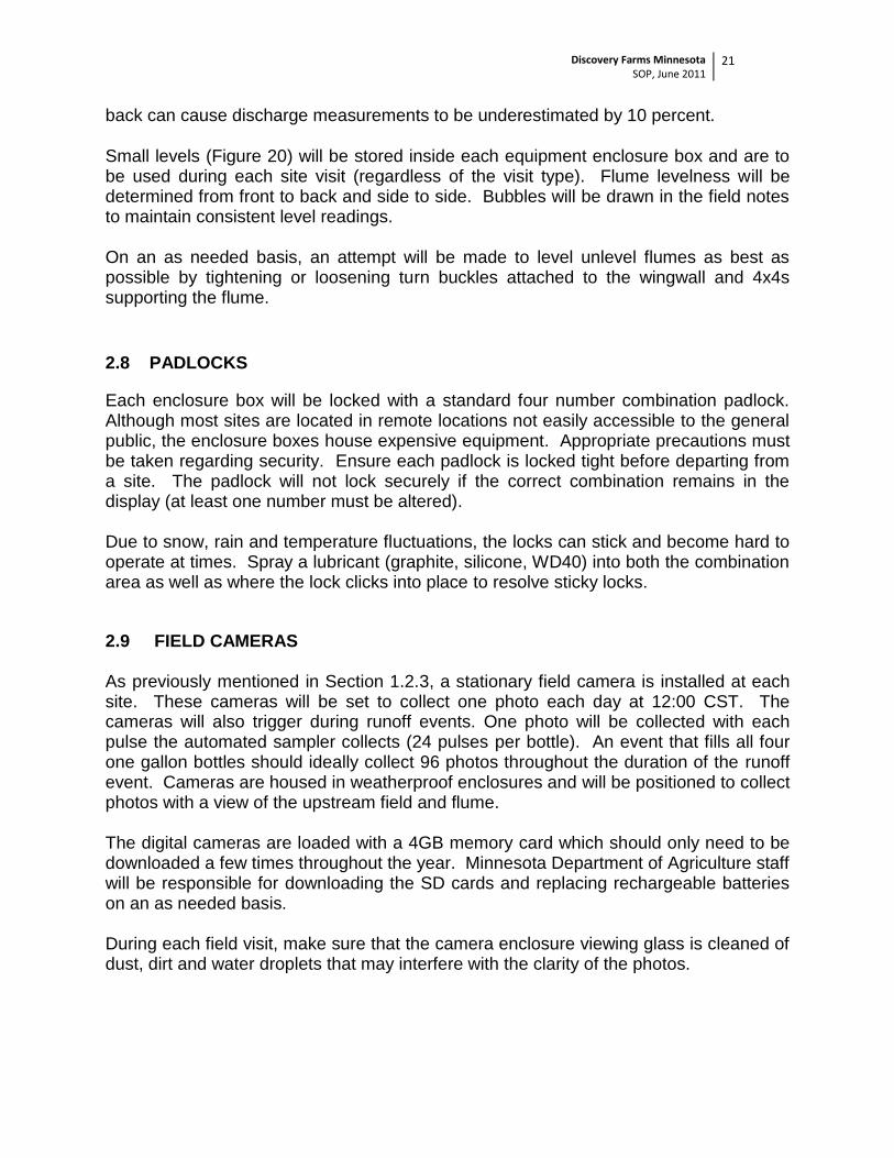
Unless properly supported, flumes are not constructed to withstand significant weight. Take care and try not to stand inside of the flume if possible. Snow removal is fairly easy and can be done with a shovel. A plastic head shovel is preferred (as metal will easily chip the flume wall). Ice removal works best with manual labor and slowly chipping away at the buildup using hand tools (such as a rock hammer, regular hammer or chisel). Again, the fiberglass flume is very delicate. Please be very careful when chipping ice in the flume. Propane heaters (paired with a canvas tarp) may also be used in cases with significant ice accumulation. A consistent heat source can prove useful to create small flowing channels of water on top of the ice. The water can help lubricate and aid in the ice removal, though extreme care must be taken with the heat sources around the fiberglass. Please refer any questions about winter maintenance to MDA staff. In addition to snow and ice removal within the flume, snow will also need to be removed upstream and downstream from the flume. An adequate channel (generally 20-30 feet) needs to be cleared downstream from the flume to eliminate the probability for backwater (Figure 15). The hand dredged channel length and width will vary and be site specific depending on the slope away from the flume and potential for backwater. Backwater conditions need to be avoided as water will not be able to get away fast enough causing the stage to be inaccurately high. This also slows the water velocity considerably making flow calculations incorrect. On the upstream side of the flume, snow must be cleared out of at least a three to six foot cone (Figure 16). This prevents melt water from cascading over the snowpack and into the flume creating turbulent conditions. The cleared area allows for water velocities
Discovery Farms Minnesota SOP, June 2011
19
to stabilize, and creates laminar flow. Often times, the snowpack upstream from the flume may be a layered mix of compacted snow and ice. A large chisel and/or mattock and scoop shovel work the best for clearing this area.
Figure 15. Snow removal area
downstream from flume.
Figure 16. Snow removal area upstream of flume.
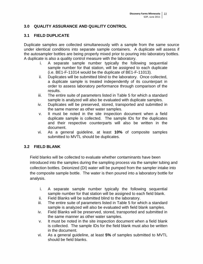
2.4 FLUME CLEANING After a runoff event, sediment and debris will likely remain on the floor of the flume (Figure 17). This residual sediment must be properly cleaned to prevent contamination of sample water during the next runoff event. Small handheld squeegees will be kept in the equipment enclosure boxes. Pour a small amount of water on the bottom of the flume to rinse. Use the squeegee to pull the water and debris out of the flume. Repeat as necessary. If the sediment is very dry, water may not be needed. Note in the site inspection document if this maintenance procedure is carried out. By pouring water into the flume, there is a small chance the bubbler could pick up a very slight increase in stage which would be erroneous and need to be removed from the data during review and corrections. A bubbler purge should be completed following cleaning of the flume.
Figure 17. Flume before and
after cleaning.
Discovery Farms Minnesota SOP, June 2011
20
2.5 PUMP TUBING REPLACEMENT New silicone sampler tubing will be installed annually or on an as-needed basis by the Minnesota Department of Agriculture staff. Only sampler tubing made specifically for ISCO 6712 autosamplers will be used. Tubing will be inspected frequently to check for cracks or significant wear. It is important to replace tubing before it fails because debris could be pushed into the pump shaft seal degrading it over time. Field blanks (see Section 3.2) will assess contamination problems from sample tubing. Refer to ISCO’s 6712 Portable Samplers Installation and Operation Guide for specific directions on pump tubing replacement. 2.6 DESICCANT A humidity indicator is located on the ISCO 6712 auto sampler face (see Figure 18). Blue color in all three pies indicates that the sampler control box is dry and clear of excess moisture. If moisture does build up within the sealed control box, the indicator will begin to turn pink (or white) beginning with the “20” pie. This means that the relative humidity inside of the box is at 20%. The 30 and 40 pies will turn pink next indicating 30 and 40% relative humidity. Once the 30 turns pink, the desiccant should be replaced by opening the controller case (see Figure 19). Contact a MDA Discovery Farms representative immediately if the 30 is pink.
Figure 18. Location of humidity indicator card
on the ISCO 6712 autosampler.
Figure 19. Location of desiccant box under
the ISCO 6712 autosampler head.
2.7 FLUME LEVELNESS Determining the levelness of the flume is critical to acquiring accurate stage measurements and subsequently flow calculations. Flumes must be level from front to back and side to side, however, this can be difficult to maintain with the freeze-thaw characteristics of winter in Minnesota. The Wisconsin Discovery Farms program has found that a tilt of just 0.02 feet from front to
Figure 20. Checking flume levelness.
Discovery Farms Minnesota SOP, June 2011
21
back can cause discharge measurements to be underestimated by 10 percent.
Small levels (Figure 20) will be stored inside each equipment enclosure box and are to be used during each site visit (regardless of the visit type). Flume levelness will be determined from front to back and side to side. Bubbles will be drawn in the field notes to maintain consistent level readings.
On an as needed basis, an attempt will be made to level unlevel flumes as best as possible by tightening or loosening turn buckles attached to the wingwall and 4x4s supporting the flume.
2.8 PADLOCKS
Each enclosure box will be locked with a standard four number combination padlock. Although most sites are located in remote locations not easily accessible to the general public, the enclosure boxes house expensive equipment. Appropriate precautions must be taken regarding security. Ensure each padlock is locked tight before departing from a site. The padlock will not lock securely if the correct combination remains in the display (at least one number must be altered). Due to snow, rain and temperature fluctuations, the locks can stick and become hard to operate at times. Spray a lubricant (graphite, silicone, WD40) into both the combination area as well as where the lock clicks into place to resolve sticky locks.
2.9 FIELD CAMERAS As previously mentioned in Section 1.2.3, a stationary field camera is installed at each site. These cameras will be set to collect one photo each day at 12:00 CST. The cameras will also trigger during runoff events. One photo will be collected with each pulse the automated sampler collects (24 pulses per bottle). An event that fills all four one gallon bottles should ideally collect 96 photos throughout the duration of the runoff event. Cameras are housed in weatherproof enclosures and will be positioned to collect photos with a view of the upstream field and flume. The digital cameras are loaded with a 4GB memory card which should only need to be downloaded a few times throughout the year. Minnesota Department of Agriculture staff will be responsible for downloading the SD cards and replacing rechargeable batteries on an as needed basis. During each field visit, make sure that the camera enclosure viewing glass is cleaned of dust, dirt and water droplets that may interfere with the clarity of the photos.
Discovery Farms Minnesota SOP, June 2011
22
3.0 QUALITY ASSURANCE AND QUALITY CONTROL 3.1 FIELD DUPLICATE Duplicate samples are collected simultaneously with a sample from the same source under identical conditions into separate sample containers. A duplicate will assess if the autosampler bottles are being properly mixed prior to pouring into laboratory bottles. A duplicate is also a quality control measure with the laboratory.
i. A separate sample number typically the following sequential sample number for that station, will be assigned to each duplicate (i.e. BE1-F-11014 would be the duplicate of BE1-F-11013).
ii. Duplicates will be submitted blind to the laboratory. Once collected, a duplicate sample is treated independently of its counterpart in order to assess laboratory performance through comparison of the results.
iii. The entire suite of parameters listed in Table 5 for which a standard sample is analyzed will also be evaluated with duplicate samples.
iv. Duplicates will be preserved, stored, transported and submitted in the same manner as other water samples.
v. It must be noted in the site inspection document when a field duplicate sample is collected. The sample IDs for the duplicates and their respective counterparts will also be written in the document.
vi. As a general guideline, at least 10% of composite samples submitted to MVTL should be duplicates.
3.2 FIELD BLANK
Field blanks will be collected to evaluate whether contaminants have been
introduced into the samples during the sampling process via the sampler tubing and
collection bottles. Deionized (DI) water will be pumped from the sampler intake into
the composite sample bottle. The water is then poured into a laboratory bottle for
analysis.
i. A separate sample number typically the following sequential sample number for that station will be assigned to each field blank.
ii. Field Blanks will be submitted blind to the laboratory. iii. The entire suite of parameters listed in Table 5 for which a standard
sample is analyzed will also be evaluated with field blank samples. iv. Field Blanks will be preserved, stored, transported and submitted in
the same manner as other water samples. v. It must be noted in the site inspection document when a field blank
is collected. The sample IDs for the field blank must also be written in the document.
vi. As a general guideline, at least 5% of samples submitted to MVTL should be field blanks.
Discovery Farms Minnesota SOP, June 2011
23
3.3 RAIN GAUGE CALIBRATION
Rain gauge calibration will be conducted once every three years by the manufacturing company, Forest Technology Systems (FTS). Rain gauges will be shipped to FTS who will then replace bearings and recalibrate the tipping mechanism. During each field visit, the rain gauge should be closely inspected to make sure that debris has not clogged the water intake. If debris is present, it should be immediately cleared out and noted on the site inspection document. Gauge levelness should also be checked on a frequent basis.
Discovery Farms Minnesota SOP, June 2011
24
4.0 DATA MANAGEMENT AND ANALYSIS Data management involves the process of data collection and storage, correcting and reviewing data, converting stage data to flow and reviewing water chemistry data. Once these steps have taken place the constituent loads, yields and flow weighted mean concentrations (FWMC) will be calculated. Surface and sub-surface stage data will be corrected using Stream Trac software available through Forest Technology Systems (FTS). Data will be assigned a quality code based on estimated accuracy and finalized flow data will be stored in a MDA database and made available through the Discovery Farms Minnesota webpage. 4.1 DATA COLLECTION AND STORAGE Data collected by the various instruments at each Discovery Farm will be recorded in the datalogger which has an internal memory of 4-6 months at current logging intervals. Each site will be instrumented with a cellular modem which allows for remote acquisition of the logger data by way of a static IP address and the Stream Trac software. Raw data will be downloaded by MDA staff daily and backed up monthly on a secured MDA network server. Logger data will be reviewed weekly to ensure all instruments are functioning properly and evaluated to look for any inconsistencies, such as outliers or missing values. Once raw data have been compiled at the end of the year, stage values must be reviewed, verified and corrected if necessary. 4.2 WATER QUANTITY ANALYSIS Surface Runoff Sites
Surface runoff sites consist of standard H flumes which are instrumented with dual stage measurement devices, an OTT brand cbs bubbler (primary measurements) and an APG brand ultrasonic transducer (secondary). Detailed field notes are of crucial importance for accurate raw data corrections. Stage data will be verified in the field by comparing bubbler and ultrasonic transducer output values with a measured stage reading. The “measured stage” will be obtained from a staff gage mounted within the flume (Section 1.2.1). Crest Stage Gauges (see Section 1.3.6) will also be installed at each surface runoff site as a backup measurement for a peak runoff stage. Dual stage measurement devices will be highly beneficial for correcting data. In situations where one instrument is tracking poorly (clogged bubbler intake, etc.) the second instrument can be used to fill the gap for missing or erroneous stage readings (and subsequently used to calculate flow). When examining stage data, both datasets will be compared closely to assess if one dataset can be used to help adjust the other.
Discovery Farms Minnesota SOP, June 2011
25
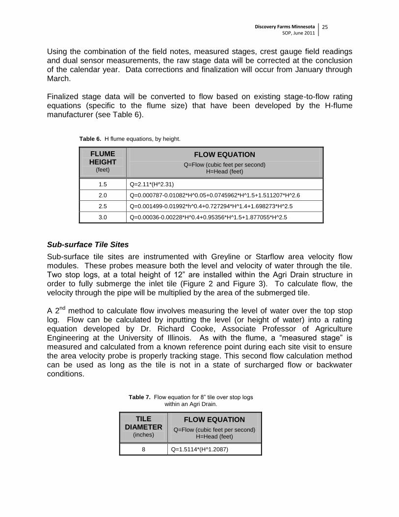
Using the combination of the field notes, measured stages, crest gauge field readings and dual sensor measurements, the raw stage data will be corrected at the conclusion of the calendar year. Data corrections and finalization will occur from January through March. Finalized stage data will be converted to flow based on existing stage-to-flow rating equations (specific to the flume size) that have been developed by the H-flume manufacturer (see Table 6).
Sub-surface tile sites are instrumented with Greyline or Starflow area velocity flow modules. These probes measure both the level and velocity of water through the tile. Two stop logs, at a total height of 12” are installed within the Agri Drain structure in order to fully submerge the inlet tile (Figure 2 and Figure 3). To calculate flow, the velocity through the pipe will be multiplied by the area of the submerged tile. A 2nd method to calculate flow involves measuring the level of water over the top stop log. Flow can be calculated by inputting the level (or height of water) into a rating equation developed by Dr. Richard Cooke, Associate Professor of Agriculture Engineering at the University of Illinois. As with the flume, a “measured stage” is measured and calculated from a known reference point during each site visit to ensure the area velocity probe is properly tracking stage. This second flow calculation method can be used as long as the tile is not in a state of surcharged flow or backwater conditions.
Table 7. Flow equation for 8” tile over stop logs
within an Agri Drain.
TILE DIAMETER
(inches)
FLOW EQUATION
Q=Flow (cubic feet per second) H=Head (feet)
8 Q=1.5114*(H^1.2087)
Discovery Farms Minnesota SOP, June 2011
26
4.3 WATER QUALITY DATA Upon receiving finalized water quality results from Minnesota Valley Testing Laboratory, results will be checked thoroughly for potential lab errors or typos. Original samples will be kept for up to 30 days, and retests will be requested for any questionable values. Approved laboratory results will be transcribed into a formatted Excel spreadsheet by Discovery Farm site ID and date. The spreadsheet will also contain the start and stop times associated with each sample and any information recorded in the field notes related to the sample (such as if subsamples were missed due to ice or clogged intake). Hard and electronic copies of the laboratory results will be filed for backup on a secured MDA network server. Prior to working up any analysis of the water quality data, all results will be thoroughly reviewed to verify that all data are present and no typos exist. 4.4 WATER QUALITY ANALYSIS Water quality and quantity (flow) data will be combined to calculate constituent loads, yields and flow weighted mean concentrations. As described in Section 1.3.4, flow composited samples will be collected during snowmelt and storm runoff periods. Each individual sample consists of up to 24 discrete 125 ml sub-samples in a one gallon jug. Each one gallon sample has a specific start and stop time, which is recorded by the datalogger. The sample results are applied to the flow period the sample was collected. For periods between samples when no water chemistry results are available, the concentration is extrapolated based on the surrounding samples. For sub-surface tile sites, baseflow sample concentrations are applied to the baseflow periods. Loads, yields, and FWMC’s will be tabulated by specific storm events, months and year. Monthly values will be used to tabulate seasonal values. 4.5 METEOROLOGICAL DATA Meteorological data collected at each site will include precipitation (FTS tipping bucket rain gauge), air temperature and humidity (FTS Temperature and Humidity Sensor). These data will be stored in 15 minute increments by the datalogger. Fifteen minute rainfall will be a total rainfall value over the previous 15 minute period. Sites will also instrumented with a manual rain gauges which will be emptied and recorded by monitoring partners after field visits that follow rain events. The manual rain gauge values will be compared to the electronic tipping bucket rain gauge to verify accuracy. 4.6 SOIL MOISTURE AND TEMPERATURE DATA A Campbell Scientific Soil Water Content Reflectometer will be installed at each site to measures the soil volumetric water content (soil moisture), bulk electrical conductivity
Discovery Farms Minnesota SOP, June 2011
27
and temperature. A Microcom Soil Temperature probe will also be instrumented at each site to measure soil temperature at four depths; 5, 10, 30 and 60cm. All meteorological and soils data will be appended and correlated with the appropriate stage, flow and water chemistry data and periodically backed up and saved in an Excel spreadsheet on a secured MDA network drive.
4.7 DATA STORAGE AND SUBMITTAL The Minnesota Pollution Control Agency manages EQuIS (Environmental Quality Information System). This database houses water quality data from sampling locations all across the state of Minnesota. The new program (implemented in 2011) replaces the older STORET and will be significantly more functional. Discovery Farms will utilize EQuIS to maintain storage of all finalized and reviewed water quality data. Data housed in the system will include all water quality parameters analyzed; total suspended sediment, ammonia, nitrate+nitrite, total kjeldahl nitrogen, total phosphorus, dissolved ortho-phosphorus and chloride. Data will be compiled into EQuIS specified templates and submit to MPCA staff for inclusion into the EQuIS database on a quarterly basis, or more/less frequently as the need permits.
Discovery Farms Minnesota SOP, June 2011
28
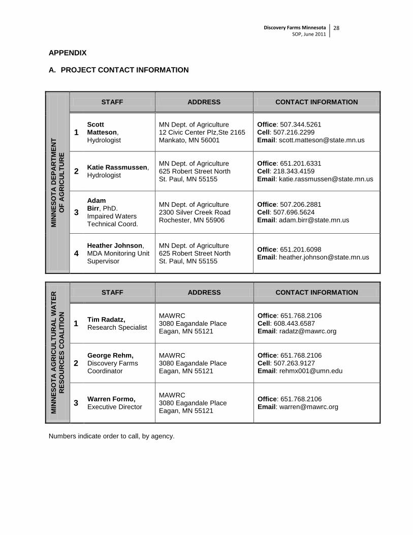
APPENDIX A. PROJECT CONTACT INFORMATION
MIN
NE
SO
TA
DE
PA
RT
ME
NT
OF
AG
RIC
UL
TU
RE
STAFF ADDRESS CONTACT INFORMATION
1 Scott Matteson, Hydrologist
MN Dept. of Agriculture 12 Civic Center Plz,Ste 2165 Mankato, MN 56001